JP5330833B2 - Method for establishing an optical trap for processing material and system for establishing an extended optical linear trap for processing material - Google Patents
Method for establishing an optical trap for processing material and system for establishing an extended optical linear trap for processing material Download PDFInfo
- Publication number
- JP5330833B2 JP5330833B2 JP2008544432A JP2008544432A JP5330833B2 JP 5330833 B2 JP5330833 B2 JP 5330833B2 JP 2008544432 A JP2008544432 A JP 2008544432A JP 2008544432 A JP2008544432 A JP 2008544432A JP 5330833 B2 JP5330833 B2 JP 5330833B2
- Authority
- JP
- Japan
- Prior art keywords
- optical
- trap
- phase
- extended
- linear trap
- Prior art date
- Legal status (The legal status is an assumption and is not a legal conclusion. Google has not performed a legal analysis and makes no representation as to the accuracy of the status listed.)
- Expired - Fee Related
Links
- 230000003287 optical effect Effects 0.000 title claims abstract description 124
- 238000000034 method Methods 0.000 title claims abstract description 32
- 239000000463 material Substances 0.000 title claims description 14
- 238000012545 processing Methods 0.000 title claims description 12
- 230000008569 process Effects 0.000 claims abstract description 3
- 238000009826 distribution Methods 0.000 claims description 13
- 238000006073 displacement reaction Methods 0.000 claims description 7
- 238000004519 manufacturing process Methods 0.000 claims description 5
- 238000000418 atomic force spectrum Methods 0.000 claims description 2
- 230000005672 electromagnetic field Effects 0.000 claims 1
- 238000012576 optical tweezer Methods 0.000 description 15
- 230000004075 alteration Effects 0.000 description 10
- 239000000523 sample Substances 0.000 description 9
- 239000002245 particle Substances 0.000 description 8
- 201000009310 astigmatism Diseases 0.000 description 7
- 238000005381 potential energy Methods 0.000 description 7
- 230000007547 defect Effects 0.000 description 6
- XLYOFNOQVPJJNP-UHFFFAOYSA-N water Substances O XLYOFNOQVPJJNP-UHFFFAOYSA-N 0.000 description 6
- 238000012937 correction Methods 0.000 description 5
- 238000001093 holography Methods 0.000 description 5
- 239000004793 Polystyrene Substances 0.000 description 4
- 230000008901 benefit Effects 0.000 description 4
- 238000003384 imaging method Methods 0.000 description 4
- 238000012986 modification Methods 0.000 description 4
- 230000004048 modification Effects 0.000 description 4
- 229920002223 polystyrene Polymers 0.000 description 4
- 238000004364 calculation method Methods 0.000 description 3
- 238000010586 diagram Methods 0.000 description 3
- 230000000694 effects Effects 0.000 description 3
- 238000005516 engineering process Methods 0.000 description 3
- 238000007654 immersion Methods 0.000 description 3
- 239000000126 substance Substances 0.000 description 3
- 238000013459 approach Methods 0.000 description 2
- 230000015572 biosynthetic process Effects 0.000 description 2
- 230000008859 change Effects 0.000 description 2
- 238000013461 design Methods 0.000 description 2
- 238000005286 illumination Methods 0.000 description 2
- 238000000651 laser trapping Methods 0.000 description 2
- 238000013507 mapping Methods 0.000 description 2
- 239000000203 mixture Substances 0.000 description 2
- 239000002070 nanowire Substances 0.000 description 2
- 230000005855 radiation Effects 0.000 description 2
- 238000012546 transfer Methods 0.000 description 2
- 230000001133 acceleration Effects 0.000 description 1
- 230000009471 action Effects 0.000 description 1
- 230000003044 adaptive effect Effects 0.000 description 1
- 230000000712 assembly Effects 0.000 description 1
- 238000000429 assembly Methods 0.000 description 1
- 238000012993 chemical processing Methods 0.000 description 1
- 238000006243 chemical reaction Methods 0.000 description 1
- 230000001427 coherent effect Effects 0.000 description 1
- 238000010276 construction Methods 0.000 description 1
- 230000008878 coupling Effects 0.000 description 1
- 238000010168 coupling process Methods 0.000 description 1
- 238000005859 coupling reaction Methods 0.000 description 1
- 239000006059 cover glass Substances 0.000 description 1
- 230000007423 decrease Effects 0.000 description 1
- 230000000593 degrading effect Effects 0.000 description 1
- 230000001419 dependent effect Effects 0.000 description 1
- 230000001066 destructive effect Effects 0.000 description 1
- 230000005684 electric field Effects 0.000 description 1
- 238000002474 experimental method Methods 0.000 description 1
- 239000012530 fluid Substances 0.000 description 1
- 239000011521 glass Substances 0.000 description 1
- 238000003780 insertion Methods 0.000 description 1
- 230000037431 insertion Effects 0.000 description 1
- 238000007689 inspection Methods 0.000 description 1
- 230000003993 interaction Effects 0.000 description 1
- 230000002452 interceptive effect Effects 0.000 description 1
- 239000004973 liquid crystal related substance Substances 0.000 description 1
- 229920002521 macromolecule Polymers 0.000 description 1
- 238000005259 measurement Methods 0.000 description 1
- 238000012544 monitoring process Methods 0.000 description 1
- 238000005457 optimization Methods 0.000 description 1
- 230000003534 oscillatory effect Effects 0.000 description 1
- 230000010363 phase shift Effects 0.000 description 1
- 238000004886 process control Methods 0.000 description 1
- 230000001902 propagating effect Effects 0.000 description 1
- 210000001747 pupil Anatomy 0.000 description 1
- 238000003908 quality control method Methods 0.000 description 1
- 238000011160 research Methods 0.000 description 1
- 230000003068 static effect Effects 0.000 description 1
- 239000000758 substrate Substances 0.000 description 1
- 230000001629 suppression Effects 0.000 description 1
- 238000012360 testing method Methods 0.000 description 1
- 230000009466 transformation Effects 0.000 description 1
- 230000007704 transition Effects 0.000 description 1
- 238000010865 video microscopy Methods 0.000 description 1
Images


Classifications
-
- G—PHYSICS
- G03—PHOTOGRAPHY; CINEMATOGRAPHY; ANALOGOUS TECHNIQUES USING WAVES OTHER THAN OPTICAL WAVES; ELECTROGRAPHY; HOLOGRAPHY
- G03H—HOLOGRAPHIC PROCESSES OR APPARATUS
- G03H1/00—Holographic processes or apparatus using light, infrared or ultraviolet waves for obtaining holograms or for obtaining an image from them; Details peculiar thereto
- G03H1/04—Processes or apparatus for producing holograms
- G03H1/08—Synthesising holograms, i.e. holograms synthesized from objects or objects from holograms
-
- G—PHYSICS
- G02—OPTICS
- G02B—OPTICAL ELEMENTS, SYSTEMS OR APPARATUS
- G02B21/00—Microscopes
- G02B21/32—Micromanipulators structurally combined with microscopes
-
- G—PHYSICS
- G03—PHOTOGRAPHY; CINEMATOGRAPHY; ANALOGOUS TECHNIQUES USING WAVES OTHER THAN OPTICAL WAVES; ELECTROGRAPHY; HOLOGRAPHY
- G03H—HOLOGRAPHIC PROCESSES OR APPARATUS
- G03H1/00—Holographic processes or apparatus using light, infrared or ultraviolet waves for obtaining holograms or for obtaining an image from them; Details peculiar thereto
- G03H1/04—Processes or apparatus for producing holograms
- G03H1/08—Synthesising holograms, i.e. holograms synthesized from objects or objects from holograms
- G03H1/0841—Encoding method mapping the synthesized field into a restricted set of values representative of the modulator parameters, e.g. detour phase coding
-
- G—PHYSICS
- G03—PHOTOGRAPHY; CINEMATOGRAPHY; ANALOGOUS TECHNIQUES USING WAVES OTHER THAN OPTICAL WAVES; ELECTROGRAPHY; HOLOGRAPHY
- G03H—HOLOGRAPHIC PROCESSES OR APPARATUS
- G03H1/00—Holographic processes or apparatus using light, infrared or ultraviolet waves for obtaining holograms or for obtaining an image from them; Details peculiar thereto
- G03H1/0005—Adaptation of holography to specific applications
- G03H2001/0077—Adaptation of holography to specific applications for optical manipulation, e.g. holographic optical tweezers [HOT]
-
- G—PHYSICS
- G03—PHOTOGRAPHY; CINEMATOGRAPHY; ANALOGOUS TECHNIQUES USING WAVES OTHER THAN OPTICAL WAVES; ELECTROGRAPHY; HOLOGRAPHY
- G03H—HOLOGRAPHIC PROCESSES OR APPARATUS
- G03H2225/00—Active addressable light modulator
- G03H2225/30—Modulation
- G03H2225/32—Phase only
Landscapes
- Physics & Mathematics (AREA)
- General Physics & Mathematics (AREA)
- Chemical & Material Sciences (AREA)
- Analytical Chemistry (AREA)
- Optics & Photonics (AREA)
- Holo Graphy (AREA)
- Exposure Of Semiconductors, Excluding Electron Or Ion Beam Exposure (AREA)
- Diffracting Gratings Or Hologram Optical Elements (AREA)
Abstract
Description
本発明は、国立科学財団によって授与された助成金番号DMR−0451589を受けて米国政府支援によって行われた。米国政府は、本発明に一定の権利を有する。 This invention was made with Government support under grant number DMR-0451589 awarded by the National Science Foundation. The US government has certain rights in the invention.
本発明は一般に、種々の用途向けに材料を処理するための拡張型光トラップを制御可能に確立するシステム及び方法に関する。詳細には、本発明は、ナノスケールの物体からマイクロメートルスケールの物体までの範囲の物体の操作、指向、操作及び処理のために、直線、曲線及び3次元形状などの種々の形状の光トラップを確立する、形状位相変調又はホログラフィの使用に関する。 The present invention generally relates to a system and method for controllably establishing an expandable optical trap for processing materials for various applications. In particular, the present invention relates to optical traps of various shapes, such as straight lines, curves and three-dimensional shapes, for manipulating, directing, manipulating and processing objects ranging from nanoscale objects to micrometer scale objects. Relates to the use of shape phase modulation or holography.
1つの点状の光トラップを直線、曲線及び3次元形状に拡張するための種々の試みが、従来技術においてなされてきた。しかしながら、深刻な欠陥が、全てのそのような尽力においてある。例えば、線状ピンセットは、円筒レンズ又はそのホログラフィック等価物を有するように実装される。しかし、円筒レンズを用いて形成される線は、著しい非点収差によって劣化する。したがって、3次元の物体を捕捉することができない。円筒レンズはまた、さらに一般的な構造を生成することができず、線状拡張型トラップのみである。線状トラップはまた、ケプラー式望遠鏡において配置される円筒レンズの対を用いて形成されている。そのような線状トラップは、非点収差から解放されることはできるが、それらの形状は一定であり、それらの強度及び位相のプロファイルを変更することはできない。そのような線状トラップはまた、ホログラフィック光トラッピング技術と互換性がなく、したがって、ホログラフィック投影によって可能な種々のトラッピング性能を組み込むことができない。別の従来技術の方法論において、拡張型光トラップは、光トラップの時分割又は走査によって形成されている。本方法は、以下に詳細に記載する種々の欠点を有する。 Various attempts have been made in the prior art to expand a point-like light trap into straight, curved and three-dimensional shapes. However, there are serious flaws in all such efforts. For example, linear tweezers are implemented to have a cylindrical lens or its holographic equivalent. However, lines formed using cylindrical lenses are degraded by significant astigmatism. Therefore, a three-dimensional object cannot be captured. Cylindrical lenses can also not produce more general structures, only linear expansion traps. The linear trap is also formed using a pair of cylindrical lenses arranged in a Kepler telescope. Such linear traps can be freed from astigmatism, but their shape is constant and their intensity and phase profiles cannot be changed. Such linear traps are also not compatible with holographic light trapping techniques and therefore cannot incorporate the various trapping capabilities possible with holographic projection. In another prior art methodology, the extended optical trap is formed by time division or scanning of the optical trap. This method has various disadvantages which are described in detail below.
さらに別の従来技術の方法論において、拡張型光トラップは、従来のホログラフィック技術によって投影されることができる。この手法は、投影された線に関して一般的な3次元構造を許容することはできず、光スペックルなどの投影欠陥を有する。さらなる欠点は、本発明の詳細の部分として以下で本明細書に記載され、従来技術に比べて実質的な利点を示す。 In yet another prior art methodology, the extended optical trap can be projected by conventional holographic techniques. This approach cannot tolerate general three-dimensional structures with respect to projected lines and has projection defects such as optical speckle. Further disadvantages are described herein below as part of the details of the present invention and show substantial advantages over the prior art.
単独ビーム光勾配力トラップは、一般化して、所定の強度を有する指定の曲線又は体積に沿ってその影響領域を確立して、光トラップの影響の直線及び体積を画定することができる。そのような拡張型トラップ及び付帯影響領域は、形状位相変調又はホログラフィを用いることによって生成されることができる。これは、さらに、複数のそのようなトラップの投影にまで拡張することができる。拡張型光トラップは、例えば、ナノスケールの物体からマイクロメートルスケールの物体を操作するため、1次元の電位エネルギ井戸に関して実装されることができる。1つの調整され、十分に特徴付けられた拡張型ポテンシャルエネルギ井戸において、そのような1つの物体、2つ以上の物体を捕捉することは、工程監視、品質制御、工程制御及びナノ製造のほか、研究及び他の分野においても種々の用途がある。 A single beam light gradient force trap can be generalized to establish its influence region along a specified curve or volume having a predetermined intensity to define a straight line and volume of influence of the light trap. Such extended traps and incidental influence regions can be generated by using shape phase modulation or holography. This can be further extended to the projection of multiple such traps. An extended optical trap can be implemented for a one-dimensional potential energy well, for example, to manipulate micrometer scale objects from nanoscale objects. Capturing one such object, two or more objects in one tuned and well-characterized extended potential energy well includes process monitoring, quality control, process control and nanofabrication, There are also various applications in research and other fields.
最も簡素な拡張型光トラップは、いわゆる線状ピンセットの形態をとり、光の適切に構造化されたビームが、スポットに対してではなく、線分に対して集束する。そのような線状ピンセットは、円筒レンズ又はそのホログラフィック等価物を用いて実装された。しかし、結果として生じるトラップは、いくつかの望ましくない特性を有する。円筒レンズによって投影される線状トラップは実際には、著しい非点収差によって劣化される従来技術の光学ピンセットの3次元構造を有する。したがって、線状トラップは、1つの平面における1つの軸に沿った直線及び別の平面における垂線に集束する。2つの直線は、ビームの軸上で交差し、その点における軸強度勾配を減少させ、したがって、3次元において物体を捕捉するそのようなトラップの性能を著しく劣化させる。円筒レンズはまた、1つの線状ピンセットのみを投影することができ、線に沿った強度及び位相のプロファイルに関する制御を提供することができない。最後に、円筒レンズは、線状の拡張型トラップのみを投影することができない。さらに、円筒レンズは、一般的な構造を投影することはできない。以下で本明細書に記載されるシステムは、それぞれが、指定の捕捉マニフォルドにおける1つの曲線に集束し、その長さに沿って独立に指定の強度及び位相のプロファイルを有する1つ又は複数の拡張型トラップの形成を可能にすることによって、これらの短所を回避する。 The simplest expandable optical trap takes the form of so-called linear tweezers, where a properly structured beam of light is focused on a line segment rather than on a spot. Such linear tweezers have been implemented using a cylindrical lens or its holographic equivalent. However, the resulting trap has several undesirable characteristics. The linear trap projected by the cylindrical lens actually has a three-dimensional structure of prior art optical tweezers that is degraded by significant astigmatism. Thus, the linear trap focuses on a straight line along one axis in one plane and a normal in another plane. The two straight lines intersect on the axis of the beam, reducing the axial intensity gradient at that point, thus significantly degrading the ability of such traps to capture objects in three dimensions. Cylindrical lenses can also project only one linear tweezer and cannot provide control over intensity and phase profiles along the line . Finally, a cylindrical lens cannot project only a linear expandable trap. Furthermore, a cylindrical lens cannot project a general structure. The system described hereinbelow is one or more extensions that each converge to a single curve in a specified capture manifold and independently have a specified intensity and phase profile along its length. By allowing the formation of mold traps, these disadvantages are avoided.
従来技術において、拡張型光トラップはまた、領域にわたって高速に1つの光ピンセットを走査することによって時分割という意味において形成されている。ピンセットが十分に高速に移動するのであれば、捕捉される物体は、ピンセットに遅れずについていくことはできず、むしろピンセットの通過の時間平均をその特性が反映する拡張したポテンシャルを受ける。これは、高いピークのレーザパワーが、中程度の平均井戸深さを維持するためであっても、必要であるという欠点を有し、感光性のサンプルを劣化する可能性がある。走査型レーザはまた、短時間照らされた物体に対して遷移エネルギ又はインパルスを与えることができ、わずかであるが、望ましくない非平衡の影響を結果として生じる可能性がある。最後に、走査型光ピンセットは通常、1つの平面のみにおいて動作し、3次元におけるさらに一般的な曲線に沿って動作することはない。本明細書に記載されたシステムは、投影型トラップのその全長にわたって、連続的な照射を提供することによって、これらの欠点を回避する。そのようなシステムはまた、以下の段落に示されるように、3次元の曲線に沿って、拡張型光トラップを投影する能力を提供する。 In the prior art, the extended optical trap is also formed in the sense of time division by scanning one optical tweezer at high speed over the area . If the tweezers move fast enough, the captured object cannot keep up with the tweezers, but rather receives an expanded potential whose characteristics reflect the time average of the tweezers passing through. This has the disadvantage that high peak laser power is necessary even to maintain a moderate average well depth, which can degrade the photosensitive sample. Scanning lasers can also provide transition energy or impulses to objects that are illuminated for short periods of time, which can result in slight but undesirable non-equilibrium effects. Finally, scanning optical tweezers typically operate in only one plane and do not operate along the more general curve in three dimensions. The system described herein avoids these drawbacks by providing continuous illumination over its entire length of the projection trap. Such a system also provides the ability to project an extended optical trap along a three-dimensional curve, as shown in the following paragraphs.
拡張型光トラップはまた、従来技術のホログラフィック法によって投影されてもよい。この場合には、所望の曲線を符号化する位相のみ又は振幅のみのホログラムが、サンプルに投影される。しかし、大部分のそのようなホログラムは、投影される線の3次元構造を指定しないため、3次元全てにおいて光トラッピングのために必要な強度勾配を最適化しない。従来のホログラフィック線状トラップはまた、スペックルなどの投影の欠陥を有する。これらは、所期のポテンシャルエネルギ井戸構造を劣化するように、投影される曲線に沿って強度分布を変化させる。そのようなホログラフィック線状トラップを符号化する位相伝達関数は、投影される強度パターンと、本質的に非線形な関係を有しており、投影欠陥を補正するための最適化は困難である。本明細書に記載されるシステムは、位相ホログラムの形状のほか、その位相値における位相及び振幅の両方の情報を符号化することによって、これらの問題点を回避する。結果は、適応して最適化されることができる指定の滑らかに変化するトラッピングパターンを結果として生じる。例えば、好ましい実施形態におけるトラップは、好適には光軸に対して垂直な線に沿って拡張され、実質的にいかなる光強度又は位相のプロファイルも、当該線に沿って設定することができる。そのような光照射は、選択された線(又は以下に説明するような曲線)に沿って連続的であってもよく、その結果、低い強度を用いることができ、サンプルの損傷を回避することができる。これらのタイプの拡張型トラップは、適切な位相及び振幅ホログラムが用いられるのであれば、従来のホログラフィックトラップシステムによって作製又は確立されることができる。これらの拡張型線状トラップはまた、光渦などのさらなるトラッピング様式と共に用いられることができ、新たな機能性を実装するように設計された光の波形における特定の動作によって定義される各モダリティを備えた拡張型光トラップと混合されることができる。 The extended optical trap may also be projected by prior art holographic methods. In this case, a phase-only or amplitude-only hologram that encodes the desired curve is projected onto the sample. However, most such holograms do not specify the three-dimensional structure of the projected line and therefore do not optimize the intensity gradient required for light trapping in all three dimensions. Conventional holographic linear traps also have projection defects such as speckle. These change the intensity distribution along the projected curve so as to degrade the intended potential energy well structure. The phase transfer function encoding such a holographic linear trap has an essentially non-linear relationship with the projected intensity pattern and is difficult to optimize to correct projection defects. The system described herein avoids these problems by encoding both the phase hologram shape as well as the phase and amplitude information at that phase value. The result results in a specified smoothly changing trapping pattern that can be adaptively optimized. For example, the traps in the preferred embodiment are preferably expanded along a line perpendicular to the optical axis, and virtually any light intensity or phase profile can be set along the line. Such light irradiation may be continuous along a selected line (or a curve as described below), so that lower intensity can be used and sample damage is avoided. Can do. These types of extended traps can be made or established by conventional holographic trap systems if the appropriate phase and amplitude holograms are used. These extended linear traps can also be used with additional trapping modalities such as optical vortices, and each modality defined by a specific action in the light waveform designed to implement new functionality. Can be mixed with the extended optical trap provided.
本発明のこれら及び他の目的、利点及び特徴は、その構成及び動作の態様と共に、添付図面に関して捉えれば、以下の詳細な説明から明白となる。以下に記載される複数の図面において、類似の要素は類似の番号を有する。 These and other objects, advantages and features of the present invention, as well as aspects of construction and operation thereof, will become apparent from the following detailed description when taken in conjunction with the accompanying drawings. In the drawings described below, like elements have like numbers.
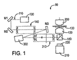
図1は、拡張型光トラップを投影するために用いられることができる一般的な光学トレイン又はシステム90を概略的に表示する。レーザ100は、光110のビームを対物レンズ120に投影し、対物レンズ120は、ビームをサンプル130の中の光トラップに集束する。通常、ビーム拡大器140が必要とされ、その結果、ビームの直径が集光レンズ120の入力アパーチャに整合し、最も強力で可能な光トラップを形成する。この実装において、レーザビーム110を対物レンズ120に反射するダイクロイックミラー150が示されている。これにより、トラップと相互に作用する物体の画像を作成されることが可能となり、画像化光が、ダイクロイックミラー150を通過する。一般的な実装において、画像化光は、集光レンズ200によってサンプル130の上に集束され、対物レンズ120によって集光され、接眼レンズ220によってカメラ210に中継されることができる。
FIG. 1 schematically represents a typical optical train or system 90 that can be used to project an expandable optical trap. The
さらなる機能性がない場合には、このシステム90は、1つの従来の光学ピンセットを投影する。適切に構成された回折光学素子(DOE)300及びさらなる中継光学素子310の追加により、システム90は拡張型光トラップを投影することが可能である。図1において、最も好ましいDOE300は、空間光変調器(SLM)であり、通常、コンピュータ制御下で、回折光学素子を定義する位相変調のパターンを符号化することができるデバイスである。DOE300のSLM形態は、トラップを形成する一連のホログラムが、投影されることになっている場合に特に有用である。しかし、本発明の実現には必要でない。拡張型光トラップの1つのパターンが必要とされる別の実装において、DOE300の静的形態は、SLMと置き換えられることができる。このシステム90は、ホログラフィック光トラップ(HOT)を投影するために有用であることが既に示され、ここの説明下の部類に加えて拡張型光トラップの複数の部類を投影するために用いられることができる。具体的には、ホログラフィック光トラップは、光渦を投影することができ、トルクのほか、光渦は、力を与えるリング状の光トラップである。HOT技術はまた、最大強度の曲線が任意の特定の曲線に沿って減少する、汎化された光渦を投影するために用いられることができる。光渦及びその汎化には、2つの主な欠点がある。与えられるトルクを削減することができず、したがって、全ての用途にとって望ましいわけではないことと、強度プロファイルを指定することができないことである。HOTはまた、1次元の軸方向の線状トラップであるベッセルビームを投影することができる。しかし、これらは、光軸に沿って線状トラップを形成することに限定されており、その長さに沿って力を生じ、その強度プロファイルを指定することができない。最後に、HOT技術はまた、円筒形の線状トラップ及びホログラフィック線状トラップを投影することができ、いずれも前述の実装問題を有する。
In the absence of further functionality, the system 90 projects one conventional optical tweezer. With the addition of a properly configured diffractive optical element (DOE) 300 and further relay
拡張型線状トラップは、それを投影するために用いられるDOE300の性質において、これらの他のタイプのホログラフィック光トラップとは異なる。特に、拡張型トラップを投影することは、ホログラムにおいて、位相及び振幅の両方の情報を符号化することを必要とするのに対し、従来のホログラフィック光トラップは、位相情報のみを必要とする。DOE300の中で位相情報が符号化される領域の形状を指定することによって、位相のみのDOEにおいて位相及び振幅の両方の情報を符号化する。拡張型光トラップを形成するために位相情報を用いることは、1つの特に有用な実施形態である。以下の段落において、形状位相変調又は形状位相ホログラフィの原理と、指定された形状及び力のプロファイルを用いて拡張型光トラップを形成するためのその用途について説明する。具体的な実施例として、均一な線状ピンセットの実装を提示する。さらに、体積測定用途のために、平面中の線分から3次元におけるさらに一般的な曲線にトラップの概要を改変するための方法について記載する。
The extended linear trap differs from these other types of holographic light traps in the nature of the
理想的な線状ピンセットは、指定された強度分布を有する線分に焦点を合わせ、線分に対して垂直な全方向において最も急峻な可能な強度勾配を有する。これは、原則的には、レンズの焦点体積における光とDOE300の平面における電界との間の数学的関係を反転することによって達成されることができる。結果は一般に、入射光の振幅及び位相の両方を変調することを含むが、これは、位相のみ又は振幅のみを変調するDOE300を考えると可能ではない。本発明における重要な点は、線状ピンセットが本質的に1次元であり、したがって、位相情報を符号化するための1次元と、振幅情報を符号化するための横方向の次元とを用いることによって、その振幅及び位相に関する両方の情報を2次元の位相のみのDOE300において符号化することができる。
An ideal linear tweezer focuses on a line segment with a specified intensity distribution and has the steepest possible intensity gradient in all directions perpendicular to the line segment. This can in principle be achieved by reversing the mathematical relationship between the light in the focal volume of the lens and the electric field in the plane of the
実施例として、レンズの焦点平面におけるy軸と整列された長さLの均一に明るい線状ピンセットを形成する。捕捉平面における領域は、以下のように近似される。

この領域の逆フーリエ変換は、DOE平面における関連する領域を生じる。
入力領域は、
Ψ(ρ)=A(ρ)exp(iφ(ρ)) (3)
と書き換え、式中のA(ρ)は、正の有限振幅であり、φ(ρ)は、実数値の位相である。式(2)の検査によって、
A(ρ)=|sinc(kρy)| (4)
であり、
Ψ (ρ) = A (ρ) exp (i φ (ρ)) (3)
Where A (ρ) in the equation is a positive finite amplitude and φ (ρ) is a real-valued phase. By inspection of equation (2),
A (ρ) = | sinc (kρ y ) | (4)
And
DOE300が均一に照らされると仮定すると、A(ρ)=A(ρx)は、トラップを形成するために通過可能なρyにおいてDOEに入射する光の部分として解釈される。画素化DOEの場合には、これは、ホログラムに寄与するρyにおける行に沿った画素の部分に対応する。他の画素を通過する光は、ホログラムに寄与せず、投影パターンから逸らさなければならない。ホログラムに寄与する領域と寄与しない領域とへ入力領域が分割される結果、形状位相ホログラムの形状成分を構成する。A(ρ)がyに沿って整列される任意の線状トラップに関してρxに独立であり、φ(ρ)は均一に明るい線の特殊な場合にはρxにも独立であることは、強調する価値がある。したがって、振幅関数A(ρy)は、ρyにおけるどれほど多くの画素がホログラムに寄与するかを指定するが、どの画素が寄与するかを指定しない。これは、多数の線状トラップのため及び以下に示すように他のトラッピング様式と線状トラップを結合するためのさらなる寛容度を提供する。
Assuming the
したがって、均一な線状ピンセットの場合、1つの適切な位相関数は、
従来の光学ピンセットを形成することに寄与する場合、割り当てられていない領域を通過する光は普通、焦点平面の中心に焦点を持ってくることになる。あるいは、光は、従来の変位位相関数を加えることによって、線からそらされることができる。
余分な光はまた、ランダムな位相値を割り当てられていない位相画素に割り当てることによって分散されることができる。最後に、余分な光は、さらなる線状ピンセットを構成するために用いられることができる。この余分な機能性は、重ならないようにするため、線状トラップを光軸に対して変位させる必要がある。割り当てられていない領域はまた、従来の光学ピンセット、光渦及び他の光トラッピング様式を作成するなどの他の用途に適用される。 Excess light can also be dispersed by assigning random phase values to unassigned phase pixels. Finally, excess light can be used to construct additional linear tweezers. This extra functionality requires the linear trap to be displaced with respect to the optical axis in order not to overlap. Unassigned areas also apply to other applications such as creating conventional optical tweezers, optical vortices and other optical trapping modalities.
例えば、均一な線状ピンセットは、
φs(ρ)=φ(ρy)S(ρ) (9)
であり、式中、
φ s (ρ) = φ (ρ y ) S (ρ) (9)
Where
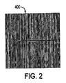
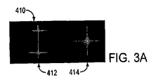
図2は、式(9)による長さL=15μmの均一な線状ピンセットを符号化し、割り当てられていない画素を用いて、50μm分横方向に変位した従来の光学ピンセットを投影する位相のみのホログラムを示す。図3Aに示された計算された強度パターンは、サンプル平面においてミラーを配置し、対物レンズを用いて反射光を集光することによって、測定される図3Bの実際の光の分布に厳密に一致する。 FIG. 2 encodes a uniform linear tweezer of length L = 15 μm according to equation (9) and uses only unphased pixels to project conventional optical tweezers laterally displaced by 50 μm. A hologram is shown. The calculated intensity pattern shown in FIG. 3A closely matches the actual light distribution of FIG. 3B measured by placing a mirror in the sample plane and collecting the reflected light using an objective lens. To do.
図2における線状トラップ410は、3つの容易に改善される欠陥を有する。式(10)によって記述された分析的形状関数は、線の端部に横方向のアーチファクトを形成する。これらは、S(ρ)を各列における正確な数の画素を割り当てるランダムな分布に置き換えることによって排除される。式(3)において必要とされる急激な強度勾配はさらに、DOEの実際の空間帯域幅を超えるため、設計された強度プロファイルから振動状の逸脱(oscillatory deviation)を生じる。これは、ギブズの現象の一例であり、トラップの設計を勾配を緩和するように改変することによって、又は標準的な数値手法を用いることによって最小限に抑えられることができる。図4A〜図4Eに示す結果は、これらの補正の利点を示している。
The
15mWの光を作動させると、これらの線状ピンセットのそれぞれは、3次元におけるマイクロメートルスケールのコロイド球を容易に捕捉すると同時に、それらに拡張軸に沿ってある程度の移動自由度を可能にする。線上に1つの粒子を配置し、ディジタルビデオ顕微鏡検査法を介して1/30秒間隔及び10nmの空間解像度でその熱的に駆動される移動を追跡することによって、直径1.5μmのポリスチレン球(Duke Scientific Lot5238)に関する拡張型トラップのポテンシャルエネルギプロファイルを特徴付ける。平衡におけるポテンシャルrのd2rの中の粒子を見つけるための確率P(r)d2rは、ボルツマンの式によって局所的なポテンシャルV(r)に関連付けられる。
P(r)=exp(−βV(r)) (11)
式中、β−1=kBTは、絶対温度Tにおける熱エネルギスケールである。10分間にわたる1つの粒子の軌跡が、図4Aの結果を生じる。長手方向のポテンシャルエネルギプロファイルは、設計された形状に厳密に従い、30±7kBTの深さである。井戸の下から3番目が、放物線プロファイルに対するフィッティングと共に図4Aにプロットされる。設計された形状からの逸脱は、0.8kBTより小さい。これらは、適応型最適化によってさらに削減可能である。横方向のプロファイルは、予想したように、球の直径によって広がる。
When activated with 15 mW of light, each of these linear tweezers easily captures micrometer-scale colloidal spheres in three dimensions while allowing them some degree of freedom of movement along the expansion axis. By placing one particle on the line and tracking its thermally driven movement at 1/30 second interval and 10 nm spatial resolution via digital video microscopy, a 1.5 μm diameter polystyrene sphere ( Characterize the potential energy profile of the extended trap for Duke Scientific Lot 5238). The probability P (r) d 2 r for finding a particle in d 2 r of the potential r at equilibrium is related to the local potential V (r) by the Boltzmann equation.
P (r) = exp (−βV (r)) (11)
In the formula, β −1 = k B T is a thermal energy scale at the absolute temperature T. One particle trajectory over 10 minutes yields the result of FIG. 4A. The longitudinal potential energy profile closely follows the designed shape and is 30 ± 7 k B T deep. The third from the bottom of the well is plotted in FIG. 4A with the fitting for the parabolic profile. Deviations from the designed shape are less than 0.8 k B T. These can be further reduced by adaptive optimization. The lateral profile broadens with the diameter of the sphere, as expected.
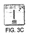
図1に示されるこのシステム90は、線状トラップ410を実装するために用いられることが好ましい。ここでは、位相関数400は、式(7)によって記述される形状位相ホログラムを組み込み、式(8)を用いて割り当てられていない光を変位させる。図3Aに示されているように、強度分布に示された拡張型線状トラップ412及びそらされるピンセット414の両方が、この位相関数400に関して計算された強度分布として示されている。実際に投影された線状トラップ412及びそらされるピンセット414の実験バーションを示す結果が、図3Bの写真に示されている。この線状トラップ412は、長さ16μmである。図3Cの差し込み写真は、水中に分散されるそれぞれが直径1.5μmの7個のポリスチレン球を捕捉するこの拡張型光トラップを示している。
This system 90 shown in FIG. 1 is preferably used to implement a
位相マスク400に対する他の改変は、本明細書には本発明以外の用途において記載され、光軸に沿って線状ピンセットを並進し、システム90の収差を補正し、位相スケーリングエラーのようなシステム90の欠陥を明らかとするといったことのために用いられることができる。
Other modifications to the
円筒レンズ又はそれらの等価物を用いて形成された線状トラップとは異なり、この形状位相ホログラフィック線状トラップ410は、単に非点収差構造ではなく、むしろ、拡張円錐の3次元の構造を有する。この構造は、最も強力な可能な軸強度勾配を生じるため、光トラッピングに適している。したがって、この構造は、基体又は他の力の供給源を介在することなく、その長さに沿って物体を十分に捕捉する。
Unlike linear traps formed using cylindrical lenses or their equivalents, this shape phase holographic
複数の拡張型光トラップは、iとjとが同一でないとき、∫ΩSi(ρ)Sj(ρ)d2ρ=0という意味で、それらの形状関数Sj(ρ)が互いに素であるならば、同一のDOEによって投影されることができる。このとき、割り当てられた領域は、領域S(ρ)=ΣjSj(ρ)である。他の状況において記載された位相マスク400に対する他の改変は、光軸に沿って線状トラップ410を並進し、光学トレインにおける収差を補正し、位相スケーリングエラーのような光学トレインにおける欠陥を明らかとするといったことに用いられることができる。最後に、形状位相変調は、位相マスク400に適切な等角写像を適用することによって、曲線状のピンセットの強度変調に関して一般化されることができる。
Multiple extended optical trap, when the i and j are not the same, in the sense that ∫ Ω S i (ρ) S j (ρ)
形状位相変調は、曲線状のピンセットの強度変調に関して一般化されることができる。このために、所望の曲線状のピンセット又はトラップに投影される逆格子における曲線を識別する。逆の曲線の強度の変調は、曲線状のピンセットに関する強度の変調を結果として生じる。所望の変調を達成するために、曲線に対して直交方向における形状は、振幅関数によって設定されるのに対し、この線に沿った各線分の位相は、擬似の1次元等価問題の位相によって決定される(直線形状の位相変調に関しても同様)。これは、2次元の曲線状のピンセット又はトラップを結果として生じる。 Shape phase modulation can be generalized for intensity modulation of curvilinear tweezers. For this purpose, the curve in the reciprocal lattice projected onto the desired curved tweezers or trap is identified. Inverse curve intensity modulation results in intensity modulation for curved tweezers. In order to achieve the desired modulation, the shape in the direction orthogonal to the curve is set by the amplitude function, whereas the phase of each line segment along this line is determined by the phase of the pseudo one-dimensional equivalent problem (Same for linear phase modulation). This results in a two-dimensional curved tweezers or trap.
等角写像(例えば、歪みのないレンズ位相)によって記述されることができる位相関数又はマスク400の追加は、この線を3次元の曲線に曲げることができ、3次元の拡張型トラップを結果として生じる。結果として生じる等角写像マスクは、振幅形状領域においてのみ含まれることができるか、(例えば、円筒レンズ位相は、直線トラップの幅を改変することを助けることができる)又は位相マスク400の全てを覆うことができる(例えば、ラジアル位相は、中心スポットから焦点平面をシフトすることができる)。したがって、形状位相変調及び従来の位相変調を混合したものを、共に適用して、混合変調モードを形成することができる。 The addition of a phase function or mask 400 that can be described by a conformal map (eg, undistorted lens phase) can bend this line into a three-dimensional curve, resulting in a three-dimensional extended trap. Arise. The resulting conformal mapping mask can be included only in the amplitude shape region (eg, the cylindrical lens phase can help modify the width of the linear trap) or the entire phase mask 400 (E.g., the radial phase can shift the focal plane from the central spot). Accordingly, a mixture of shape phase modulation and conventional phase modulation can be applied together to form a mixed modulation mode.
光トラップの3次元への拡張
以下において、形成することができ、他のクラスの拡張型光トラップ比較されることができる、拡張型光トラップの3次元強度分布の詳細図が提供される。
In the following, a detailed view of the three-dimensional intensity distribution of an extended optical trap that can be formed and compared with other classes of extended optical traps is provided.
これらの実施形態は、図5において概略的に示される好ましい最適化されたホログラフィックトラッピング技術に基づいている。ここでは、波長λ=532nmで動作する周波数逓倍固体レーザ(図示せず)(Coherent Verdi)からのレーザ光500のビーム500が、中継光学素子505を介して高開口数の対物レンズ510(Nikon 100X Plan Apo,NA 1.4,油浸)の入力瞳に向けられ、そのビーム500を光トラップに集束する。レーザビーム500は、対物レンズの入力平面に結合する平面において、コンピュータアドレス制御される液晶空間光変調器520(SLM,Hamamatsu X8267 PPM)による位相のみのホログラムとして刻印される。その結果、対物レンズの焦点平面における光領域Ψ(r)が、公知のフラウンホーファ変換によってSLM520の平面における領域に関連付けられる。
Ψ(ρ)=u(ρ)exp(iφ(ρ)) (13)
式中、φ(ρ)は、SLM520によってレーザビーム500に刻印される実数値の位相プロファイルである。本発明者のシステムにおけるSLM520は、768×768のアレイの各画素で0〜2πラジアンの位相シフトを強いる。この2次元の位相アレイは、それぞれが、個別に指定された強度特性及び波面特性を備えた光トラップの任意の所望の3次元の構成に1つの光学ピンセットを変換するように設計されたコンピュータ生成による位相のみのホログラムφ(ρ)を投影するために用いられることができる。
These embodiments are based on the preferred optimized holographic trapping technique shown schematically in FIG. Here, a
Ψ (ρ) = u (ρ) exp (iφ (ρ)) (13)
Where φ (ρ) is a real-valued phase profile imprinted on the
通常は、ホログラフィック光トラップのパターンは、それを対物レンズの焦点平面に取り付けられた流体によって運ばれるサンプルに投影することによって用いるために向けられる。光領域を特徴付けるため、代わりにサンプル平面において前面ミラーを取り付ける。このミラーは、捕捉光を対物レンズ510に戻すように反射し、部分反射ミラー540を介して荷結合素子(CCD)カメラ530(NEC TI324AII)にトラップの画像を送信する。本発明の実装において、対物レンズ510、カメラ接眼レンズは、従来の光学顕微鏡(Nikon TE−2000U)に取り付けられる。
Typically, the pattern of the holographic light trap is oriented for use by projecting it onto a sample carried by a fluid attached to the focal plane of the objective lens. To characterize the light region , a front mirror is attached instead at the sample plane. This mirror reflects the captured light back to the
光トラップの強度分布の3次元の再構成は、対物レンズ510に対してミラー540を並進することによって得られることができる。同等に、トラップは、放物線の位相関数をトラップの特定のパターンを符号化するホログラムφ0(ρ)の上に重ねることによって、固定ミラー550に対して並進させることができる。
対物レンズ510は、z≦0の場合には反射光の全てを本質的に捕獲する。しかし、z>0の場合には、収束トラップの一番外側の光線が、対物レンズの出力瞳によって遮断され、したがって、コントラストが減少する。これは、z>0の場合には測定された強度の領域にzに比例する係数を乗算することによって補正することが可能である。しかし、適切な係数を正確に決定することは困難であるため、元のままの結果しか提供しない。
The
図6A〜図6Dは、このように再構成され、5%のピーク強度及び3つの断面における等強度面として表示された従来の光学ピンセットを示している。ピーク強度は、収束光の全体的な構造を示すために有用であり、断面は、光学的に捕捉された物体を閉じ込める3次元の光領域の印象を提供する。これらのデータから得られた浸漬油における収束角63°は、全体的な開口数1.4と一致する。最も鮮明な焦点の半径rmin≒0.2μmは、ビームを集束する回折限界と一致する。 6A-6D show conventional optical tweezers reconstructed in this way and displayed as 5% peak intensity and isointensity surfaces in three cross-sections. The peak intensity is useful to show the overall structure of the focused light, and the cross section provides the impression of a three-dimensional light region that confines the optically captured object. The convergence angle of 63 ° in the immersion oil obtained from these data is consistent with the overall numerical aperture of 1.4. The sharpest focus radius r min ≈0.2 μm coincides with the diffraction limit for focusing the beam.
これらの結果は、この再構成技術の2つのさらなる態様を際立たせる。対物レンズ510は、水を通過する光がガラスのカバーガラスによって屈折されるとき、球面収差を補正するように設計される。このさらなる屈折がないと、投影された光トラップは実際に、対物レンズ510によって持ち込まれた約20λの球面収差まで劣化される。これは、見かけの開口数を低減し、z軸に沿ったトラップの焦点も広げる。水中におけるトラップの実効開口数は、約1.2である。球面収差の影響は、さらなる位相プロファイルを有するビームを予め変形することによって略補正されることができる。
ゼルニケの多項式は、球面収差を記述する。半径xは、光学トレインの開口の一部として測定され、係数aは、光の波長において測定される。この手順は、実際の光トラッピングシステムに存在する小量の収差を補正するために用いられ、性能の最適化を図る。 Zernike polynomials describe spherical aberration. The radius x is measured as part of the aperture of the optical train and the coefficient a is measured at the wavelength of light. This procedure is used to correct a small amount of aberrations present in an actual optical trapping system to optimize performance.
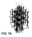
図7A及び図7Bに示されるように、3次元で再構成したものとして35個の光学ピンセットのアレイに、この補正が適用された。図7Aのこれらの光トラップは、格子定数10.8μmの図7Bの3次元の体心立方(BCC)格子に配置される。球面収差を補正しない場合には、これらのトラップは、光軸に沿って互いに混ざり合うことになる。補正を用いると、軸方向の強度勾配が、明確に分解される。これは、光軸に沿って物体を体系化するためのホログラフィックトラップの能力に原因がある。 This correction was applied to an array of 35 optical tweezers as reconstructed in three dimensions, as shown in FIGS. 7A and 7B. These optical traps of FIG. 7A are arranged in the three-dimensional body-centered cubic (BCC) grating of FIG. 7B with a lattice constant of 10.8 μm. If the spherical aberration is not corrected, these traps will mix with each other along the optical axis. With correction, the axial intensity gradient is clearly resolved. This is due to the ability of holographic traps to organize objects along the optical axis.
水ではなく、浸漬油に投影することによって生じた球面収差の量は、とても大きい。したがって、収差補正のないさらに複雑なトラップを提供する。特に、最近導入されたホログラフィック技術によって作製された拡張型光トラップの相対的な利点を示すために、補正していない容積画像化を用いた。 The amount of spherical aberration caused by projecting on immersion oil rather than water is very large. Therefore, a more complicated trap without aberration correction is provided. In particular, uncorrected volumetric imaging was used to show the relative advantages of extended optical traps made by recently introduced holographic techniques.
拡張型光トラップは、トラップの所期の輪郭に沿って、従来の光学ピンセットを高速で走査することによって、時分割という意味で投影されていた。走査型トラップは、点状光学ピンセットと同程度の光学特性と、瞬間走査速度を調整することによって調整することができる実効ポテンシャルエネルギ井戸を有する。トラップの移動に起因する運動学的影響は、十分に高速に走査することによって最小限に抑えられることができる。しかし、いくつかの用途に関して、連続照射又は走査機能を持たない光学トレインの簡素さが望ましい場合がある。 Extended optical trap along the intended contour of the trap, by scanning conventional optical tweezers at high speed, has been projected in the sense of time division. The scanning trap has optical properties comparable to point-like optical tweezers and an effective potential energy well that can be adjusted by adjusting the instantaneous scanning speed. Kinematic effects due to trap movement can be minimized by scanning sufficiently fast. However, for some applications, the simplicity of an optical train that does not have continuous illumination or scanning capabilities may be desirable.
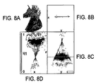
連続的に照射される線状トラップは、1方向に沿って光トラップを拡張することによって作製された。これは、例えば、円筒レンズを対物レンズの入力平面に導入することによって達成されることができる。同等に、円筒レンズ式ピンセットは、SLM520で関数φc(ρ)=πz0ρ2 x/(λ∫2)を符号化することによって実装されることができる。図8A〜図8Dに示される結果は、略一様な強度プロファイル及び放物線位相を有する線まで拡張された状態の点状のピンセットについて、最良の焦点平面z=z0で有用であるように見える。しかし、図8Aにおける3次元による再構成によれば、円筒レンズが、大量の非点収差をビームに持ち込んだにすぎず、第1の焦線に垂直な第2の焦線を形成していることが明らかである。これは、非点収差ビームの強度勾配が、従来の光学ピンセットに比べて、光軸に沿って著しく弱くなっているため、問題である。したがって、円筒レンズ型線状トラップは通常、光軸に沿った放射圧力に対して物体を局所化することはできない。
Continuously irradiated linear traps were made by extending the light trap along one direction. This can be achieved, for example, by introducing a cylindrical lens into the input plane of the objective lens. Equivalently, cylindrical lens tweezers can be implemented by encoding the function φ c (ρ) = πz 0 ρ 2 x / (λ∫ 2 ) in the
1つの円筒レンズを円筒形のケプラー式望遠鏡に置き換えることにより、非点収差を低減し、したがって、安定した3次元の光トラップを作成する。同様に2つの干渉ビームを集束するために、対物レンズを用いることは、3次元トラッピングを可能にする干渉型光トラップを作成する。しかし、この手法は、拡張型トラップの強度プロファイルに関してほとんど制御せず、位相プロファイルに関する制御も提供しない。 Replacing one cylindrical lens with a cylindrical Kepler telescope reduces astigmatism and thus creates a stable three-dimensional optical trap. Similarly, using an objective lens to focus the two interfering beams creates an interferometric optical trap that allows for three-dimensional trapping. However, this approach has little control over the intensity profile of the extended trap and provides no control over the phase profile.
形状位相ホログラフィは、回折効率を犠牲にして、拡張型光トラップの振幅及び位相の両方のプロファイルに関する確実な制御を提供する。3次元トラッピングに適した最適な軸強度勾配を有するトラップも生じる。線状トラップが、対物レンズの焦点平面におけるρx方向に沿った振幅プロファイルu(ρx)及び位相プロファイルp(ρx)によって特徴付けられる場合には、SLM平面における領域は、式(12)によって以下のように与えられる。
Ψ(ρ)=u(ρx)exp(ip(ρx)) (16)
このとき、位相p(ρx)は、u(ρx)>0であるように調整される。形状位相ホログラフィは、この1次元の複雑な波面プロファイルを2次元の位相のみのホログラムとして実装する。
Ψ (ρ) = u (ρ x ) exp (ip (ρ x )) (16)
At this time, the phase p (ρ x ) is adjusted so that u (ρ x )> 0. Shape phase holography implements this one-dimensional complex wavefront profile as a two-dimensional phase-only hologram.
円筒レンズトラップとは異なり、ホログラフィック線状トラップは、対物レンズの焦点平面における1つの回折限界線における円錐形のくさびとして集束する。したがって、収束のその横方向の角度は、最適な点トラップの角度に匹敵する。このことは、ホログラフィック線状トラップが比較的強い軸強度勾配を有し、ホログラフィック線状トラップがz方向における放射圧力に対して物体を安定にトラップする能力があることを明らかにしている。 Unlike cylindrical lens traps, holographic linear traps converge as a conical wedge at one diffraction limit line in the focal plane of the objective lens. Therefore, its lateral angle of convergence is comparable to the optimal point trap angle. This reveals that the holographic linear trap has a relatively strong axial intensity gradient and that the holographic linear trap is capable of stably trapping an object against radiation pressure in the z direction.
線状トラップの横方向の収束は、線に沿った強度プロファイルの選択にあまり左右されない。しかし、その3次元の強度分布は、線に沿った位相プロファイルに対してきわめて敏感である。急激な位相変化は、弱め合う干渉によって、線状トラップの強度の局所的な抑制を生じる。より滑らかな変動は、線に沿った強度プロファイルに影響しないが、実質的にビームを再構成することができる。例えば、円筒レンズによって作製される線状トラップは、放物線強度プロファイルのほか、放物線位相プロファイルも有する。式13にこの選択を導入し、式(12)及び式(17)を用いて関連する形状位相ホログラムを計算することにより、理想化された円筒レンズの位相伝達関数を生じる。この観察は、線に沿った位相プロファイルが所望の3次元の強度分布を形成するように同調されることができる用途又は測定された3次元の強度分布が、線に沿って位相プロファイルを評価するために用いられることができる用途に通じている。
The lateral convergence of the linear trap is less dependent on the choice of intensity profile along the line. However, its three-dimensional intensity distribution is very sensitive to the phase profile along the line. A sudden phase change causes local suppression of the strength of the linear trap due to destructive interference. Smoother variations do not affect the intensity profile along the line, but can substantially reconstruct the beam. For example, a linear trap made by a cylindrical lens has a parabolic phase profile as well as a parabolic intensity profile. Introducing this selection into
材料の操作、探査、選択的化学反応及び生物学的反応、試験、作製及び結集を無制限に含む材料の化学処理、機械処理、電気処理及び生物学的処理に関して拡張型光トラップを用いた種々の用途が考えられる。一例の用途において、機能化された球(又は任意のタイプの粒子又は塊)が、拡張型光トラップとして確立された線に沿って位置決めされることができる。そのようなアセンブリ又は粒子はまた、容易に確認される粒子間で探査及び反応及び相互作用を行うこともできる。さらに、ナノワイヤは、拡張型トラップを用いて容易に操作、探査及び処理を行われることができる。粒子又はナノワイヤ又は他のメスコピック(mescopic)材料は、そのような拡張型トラップのプログラム可能なポテンシャル井戸において配置されて、捕捉された材料の相互作用及び特性を測定することができる。測定はまた、粒子又は材料のより複雑な2次元又は3次元の構成からの情報にデコンボリューションを行わなくても形成されることができるそのような十分に確立された1次元の状態下で、容易に行われることができる。類似の材料及び類似でない材料はいずれも、拡張型光トラップによって探査されることができ、光学的外乱又は他の複雑化の補正は、拡張型光トラップ理論を用いて容易に達成されることができる。これらの技術は、物理系、化学系、電子系、機械系、光学系及び生物系に関して多様な用途を有する。さらに、拡張型光トラップは、それらのプログラム可能な性質及び互換性のために、製作目的及び結集目的に利用されることができる。化学用途、生物用途及び電気用途において、そのような拡張型トラップは、材料をプログラム可能に反応させ、マクロ分子、電子回路を結集し、今まで達成可能でなかったナノスケールの生物媒体を作製するために用いられることができる。製作及び処理の分野において、位相のみのパターンが直線又は曲線に沿って加えられ、強度が一定のままであるが、光学的強度を任意のプロファイルにプログラムして、移動、加速及び減速を可能にし、ナノ製造組み立て又は生産ラインの一部をなすことができる。さらに別の実施例において、拡張型光トラップを用いる微小流体系が考えられ、動作させることができる。 Various using optical traps for chemical processing, mechanical processing, electrical processing and biological processing of materials including unlimited manipulation, exploration, selective chemical and biological reactions, testing, fabrication and assembly Possible uses. In one example application, a functionalized sphere (or any type of particle or mass) can be positioned along a line established as an expandable light trap. Such assemblies or particles can also probe and react and interact between easily identified particles. Furthermore, nanowires can be easily manipulated, explored and processed using an expandable trap. Particles or nanowires or other mesoscopic materials can be placed in the programmable potential well of such an extended trap to measure the interaction and properties of the captured material. Measurements can also be made under such well-established one-dimensional conditions that can be made without deconvolution of information from more complex two-dimensional or three-dimensional configurations of particles or materials. Can be done easily. Both similar and dissimilar materials can be probed by an extended optical trap, and optical disturbances or other complication corrections can be easily achieved using extended optical trap theory. it can. These technologies have various uses regarding physical systems, chemical systems, electronic systems, mechanical systems, optical systems, and biological systems. In addition, extended optical traps can be utilized for fabrication and assembly purposes because of their programmable nature and compatibility. In chemical, biological, and electrical applications, such extended traps allow materials to be programmably reacted, bringing together macromolecules, electronic circuits, and creating nanoscale biological media that were previously unattainable. Can be used for. In the field of fabrication and processing, a phase-only pattern is added along a straight line or curve and the intensity remains constant, but the optical intensity is programmed to an arbitrary profile to allow movement, acceleration and deceleration. Can be part of a nanofabrication assembly or production line. In yet another embodiment, a microfluidic system using an expandable optical trap can be envisioned and operated.
本明細書に記載される実施形態において言及される種々の変更及び改変は、当業者には明白であることを理解すべきである。そのような変更及び改変は、本発明の精神及び範囲を逸脱することなく行われることができる。 It should be understood that various changes and modifications noted in the embodiments described herein will be apparent to those skilled in the art. Such changes and modifications can be made without departing from the spirit and scope of the invention.
Claims (17)
2次元回折光学素子に前記光ビームを適用するステップと
を含む、材料を処理するための光トラップを確立する方法であって、
拡張型光トラップを3次元の曲線に沿って作成するため、独立に指定された位相情報及び振幅情報を提供することであって、前記拡張型光トラップが拡張型光学線状トラップであり、前記2次元回折光学素子において前記位相情報及び振幅情報を符号化することと、1つの選択した次元を用いて位相情報を符号化することと、前記1つの選択した次元に対する横方向の次元を用い振幅情報を符号化することとを含むことと、
材料を処理するために前記拡張型光学線状トラップを用いることを特徴とする、方法。 Providing a light beam;
Applying a light beam to a two-dimensional diffractive optical element, and establishing a light trap for processing material comprising:
Providing independently specified phase information and amplitude information to create an extended optical trap along a three-dimensional curve, wherein the extended optical trap is an extended optical linear trap, Encoding the phase information and amplitude information in a two-dimensional diffractive optical element; encoding phase information using one selected dimension; and amplitude using a lateral dimension relative to the one selected dimension. Encoding the information; and
A method characterized in that the expandable optical linear trap is used to process a material.
S(ρ)=φs(ρ)/φ(ρy) (9)
式中、
S (ρ) = φ s (ρ) / φ (ρ y ) (9)
Where
Ψ(ρ)=u(ρ)exp(iφ(ρ)) (13)
(Ψは、関数として示した光領域、ρは実空間変数rからフーリエ変換された逆空間変数、前記回折光学素子で、uは振幅プロファイル、φは位相プロファイルである。)
で表わされる請求項12に記載の方法。 The field function is
Ψ (ρ) = u (ρ) exp (iφ (ρ)) (13)
(Ψ is an optical region shown as a function, ρ is an inverse space variable Fourier-transformed from a real space variable r, the diffractive optical element, u is an amplitude profile, and φ is a phase profile.)
The method of claim 12 represented by:
前記光ビームを処理する2次元回折光学素子であって、3次元の曲線に沿って拡張型光学線状トラップを作成するために独立に指定された位相情報及び振幅情報であって、前記2次元回折光学素子において符号化された位相情報及び振幅情報によって形成され、符号化された位相情報を有する1つの選択された次元と、符号化された振幅情報を有する前記選択された次元に対する横方向の次元とを備える位相情報及び振幅情報を含む、回折光学素子と、
前記拡散光学素子によって処理された光ビームを投影し、材料の処理を実行する光学トレインと
を備える、材料を処理するための拡張型光学線状トラップを確立するシステム。 A light source providing a light beam;
A two-dimensional diffractive optical element for processing the light beam, the phase information and the amplitude information specified independently to create an expandable optical linear trap along a three-dimensional curve, the two-dimensional formed by the phase information and amplitude information encoded in the diffractive optical element, and one selected dimension having a phase information encoded in the horizontal direction with respect to the selected dimension having an amplitude encoded information A diffractive optical element comprising phase information and amplitude information comprising dimensions;
A system for establishing an expandable optical linear trap for processing material comprising: an optical train for projecting a light beam processed by the diffusing optical element and performing processing of the material.
Applications Claiming Priority (7)
| Application Number | Priority Date | Filing Date | Title |
|---|---|---|---|
| US74244405P | 2005-12-05 | 2005-12-05 | |
| US60/742,444 | 2005-12-05 | ||
| US77762206P | 2006-02-28 | 2006-02-28 | |
| US60/777,622 | 2006-02-28 | ||
| US85225206P | 2006-10-17 | 2006-10-17 | |
| US60/852,252 | 2006-10-17 | ||
| PCT/US2006/046368 WO2007067524A2 (en) | 2005-12-05 | 2006-12-05 | Extended optical traps by shape-phase holography |
Publications (3)
| Publication Number | Publication Date |
|---|---|
| JP2009518688A JP2009518688A (en) | 2009-05-07 |
| JP2009518688A5 JP2009518688A5 (en) | 2013-08-01 |
| JP5330833B2 true JP5330833B2 (en) | 2013-10-30 |
Family
ID=38051125
Family Applications (1)
| Application Number | Title | Priority Date | Filing Date |
|---|---|---|---|
| JP2008544432A Expired - Fee Related JP5330833B2 (en) | 2005-12-05 | 2006-12-05 | Method for establishing an optical trap for processing material and system for establishing an extended optical linear trap for processing material |
Country Status (5)
| Country | Link |
|---|---|
| US (2) | US7491928B2 (en) |
| EP (1) | EP1958211A2 (en) |
| JP (1) | JP5330833B2 (en) |
| CN (1) | CN101336455B (en) |
| WO (1) | WO2007067524A2 (en) |
Families Citing this family (26)
| Publication number | Priority date | Publication date | Assignee | Title |
|---|---|---|---|---|
| WO2007015199A2 (en) * | 2005-08-04 | 2007-02-08 | Koninklijke Philips Electronics, N.V. | Motion compensation in functional imaging |
| US7491928B2 (en) * | 2005-12-05 | 2009-02-17 | New York University | Extended optical traps by shape-phase holography |
| JP2007313378A (en) * | 2006-05-23 | 2007-12-06 | Keio Gijuku | Optical material handling device |
| US7847238B2 (en) * | 2006-11-07 | 2010-12-07 | New York University | Holographic microfabrication and characterization system for soft matter and biological systems |
| TWI322280B (en) * | 2007-01-24 | 2010-03-21 | Raydium Semiconductor Corp | Apparatus capable of providing optical tweezers with momentum and method thereof |
| JP4984938B2 (en) * | 2007-02-07 | 2012-07-25 | 大日本印刷株式会社 | Optical element and manufacturing method thereof |
| US20100204459A1 (en) * | 2007-08-27 | 2010-08-12 | The Regents Of The University Of California | Systems and methods for producing multi-component colloidal structures |
| JP5365982B2 (en) * | 2008-10-02 | 2013-12-11 | 株式会社ニコン | Illumination optical system, exposure apparatus, and device manufacturing method |
| CN102365543A (en) | 2009-01-16 | 2012-02-29 | 纽约大学 | Automated real-time particle characterization and three-dimensional velocimetry with holographic video microscopy |
| US8928969B2 (en) | 2011-12-06 | 2015-01-06 | Ostendo Technologies, Inc. | Spatio-optical directional light modulator |
| US8854724B2 (en) | 2012-03-27 | 2014-10-07 | Ostendo Technologies, Inc. | Spatio-temporal directional light modulator |
| JP5982993B2 (en) * | 2012-04-25 | 2016-08-31 | 大日本印刷株式会社 | Hologram manufacturing apparatus and hologram manufacturing method |
| US9179126B2 (en) | 2012-06-01 | 2015-11-03 | Ostendo Technologies, Inc. | Spatio-temporal light field cameras |
| US9658443B2 (en) | 2013-03-15 | 2017-05-23 | The Board Of Trustees Of The Leland Stanford Junior University | Optics apparatus with detection of light rays received at different angles for output indicative of aliased views |
| TWI614569B (en) * | 2013-04-01 | 2018-02-11 | Kla-Tencor Corporation | Method and system for detecting defects in a reticle |
| US9315846B2 (en) * | 2014-02-13 | 2016-04-19 | The United States Of America As Represented By Secretary Of The Navy | Fluidic channel based on a filtered, free-space electromagnetic wave source |
| US10317597B2 (en) | 2014-08-26 | 2019-06-11 | The Board Of Trustees Of The Leland Stanford Junior University | Light-field microscopy with phase masking |
| EP3218690B1 (en) | 2014-11-12 | 2022-03-09 | New York University | Colloidal fingerprints for soft materials using total holographic characterization |
| JP6582867B2 (en) | 2015-10-22 | 2019-10-02 | 株式会社ジェイテクト | Optical tweezers |
| DK3414517T3 (en) | 2016-02-08 | 2021-12-13 | Univ New York | HOLOGRAPHIC CHARACTERIZATION OF PROTEIN UNITS |
| CN106908946B (en) * | 2016-05-05 | 2019-03-22 | 中国计量大学 | A Simplified Dual-Beam Optical Tweezers System |
| US11543338B2 (en) | 2019-10-25 | 2023-01-03 | New York University | Holographic characterization of irregular particles |
| US11948302B2 (en) | 2020-03-09 | 2024-04-02 | New York University | Automated holographic video microscopy assay |
| EP4170411B1 (en) * | 2021-10-21 | 2025-01-15 | The Swatch Group Research and Development Ltd | Magnifying device with multiple magnification |
| CN113946116B (en) * | 2021-10-29 | 2025-04-22 | 上海交通大学 | Compact measurement device, method and medium for three-dimensional displacement in holographic range of scattered light field |
| CN121163660A (en) * | 2025-09-12 | 2025-12-19 | 重庆理工大学 | Laser array pointing error regulation and control system based on programmable light intensity gradient potential well |
Family Cites Families (8)
| Publication number | Priority date | Publication date | Assignee | Title |
|---|---|---|---|---|
| US6055106A (en) | 1998-02-03 | 2000-04-25 | Arch Development Corporation | Apparatus for applying optical gradient forces |
| DE60124524T2 (en) * | 2000-04-25 | 2007-03-08 | Asml Holding, N.V. | OPTICAL REDUCTION SYSTEM WITH CONTROL OF EXPOSURE POLARIZATION |
| US6737634B2 (en) | 2002-01-16 | 2004-05-18 | The University Of Chicago | Use of multiple optical vortices for pumping, mixing and sorting |
| US7109473B2 (en) * | 2002-09-16 | 2006-09-19 | University Of Chicago | Transverse optical accelerator and generalized optical vortices |
| GB2408587A (en) * | 2003-11-28 | 2005-06-01 | Univ Hertfordshire | Optical particle manipulation systems |
| US7473890B2 (en) * | 2004-11-23 | 2009-01-06 | New York University | Manipulation of objects in potential energy landscapes |
| US7491928B2 (en) * | 2005-12-05 | 2009-02-17 | New York University | Extended optical traps by shape-phase holography |
| US7835051B2 (en) * | 2006-10-17 | 2010-11-16 | New York University | Volumetric imaging of holographic optical traps |
-
2006
- 2006-12-04 US US11/633,178 patent/US7491928B2/en active Active
- 2006-12-05 JP JP2008544432A patent/JP5330833B2/en not_active Expired - Fee Related
- 2006-12-05 WO PCT/US2006/046368 patent/WO2007067524A2/en not_active Ceased
- 2006-12-05 CN CN2006800519619A patent/CN101336455B/en not_active Expired - Fee Related
- 2006-12-05 EP EP06844831A patent/EP1958211A2/en not_active Withdrawn
-
2009
- 2009-02-09 US US12/368,163 patent/US7897910B2/en not_active Expired - Fee Related
Also Published As
| Publication number | Publication date |
|---|---|
| HK1128060A1 (en) | 2009-10-16 |
| JP2009518688A (en) | 2009-05-07 |
| WO2007067524A2 (en) | 2007-06-14 |
| WO2007067524A3 (en) | 2007-08-09 |
| US20070139784A1 (en) | 2007-06-21 |
| EP1958211A2 (en) | 2008-08-20 |
| CN101336455B (en) | 2013-04-10 |
| US20090146050A1 (en) | 2009-06-11 |
| CN101336455A (en) | 2008-12-31 |
| US7897910B2 (en) | 2011-03-01 |
| US7491928B2 (en) | 2009-02-17 |
Similar Documents
| Publication | Publication Date | Title |
|---|---|---|
| JP5330833B2 (en) | Method for establishing an optical trap for processing material and system for establishing an extended optical linear trap for processing material | |
| US7847238B2 (en) | Holographic microfabrication and characterization system for soft matter and biological systems | |
| JP2009518688A5 (en) | Method for establishing an optical trap for processing material and system for establishing an extended optical linear trap for processing material | |
| US7232989B2 (en) | Transverse optical accelerator and generalized optical vortices | |
| US8472094B2 (en) | Volumetric is imaging of a holographic optical traps | |
| JP5802109B2 (en) | Light modulation control method, control program, control device, and laser light irradiation device | |
| Piestun et al. | Synthesis of three-dimensional light fields and applications | |
| Georgieva et al. | Optimization of DMD-based independent amplitude and phase modulation by analysis of target complex wavefront | |
| Stuerwald | Digital holographic methods | |
| Kelemen et al. | Two-photon polymerization with optimized spatial light modulator | |
| Hayasaki et al. | Spatial Beam Shaping with a Liquid-Crystal Spatial Light Modulator for Surface Micro-and Nanoprocessing | |
| HK1128060B (en) | Extended optical traps by shape-phase holography | |
| Anand et al. | 3D Incoherent Imaging Using an Ensemble of Sparse Self-Rotating Beams | |
| Cho et al. | Rotationally symmetric phase filter design for extended depth-of-focus using automatic differentiation | |
| Ren | Aberration-Free 3-D Scanning Based on Digital Holography for Advanced Imaging and Nanofabrication Applications | |
| Carbonell Leal | Complex spatial shaping of femtosecond pulses with phase-only spatial light modulators | |
| Rathore | Microscopic Trapping and High-Resolution Imaging of Ultra Cold Rydberg Atoms | |
| Cholis et al. | Roichman et a1. | |
| CN113916848A (en) | Beam generation method and system for stimulated radiation loss imaging through strongly scattering media | |
| Lee | Brownian motion in complex potential energy landscapes created with light | |
| Moradi et al. | Force trapping gradient using diffractive optical elements |
Legal Events
| Date | Code | Title | Description |
|---|---|---|---|
| A131 | Notification of reasons for refusal |
Free format text: JAPANESE INTERMEDIATE CODE: A131 Effective date: 20110506 |
|
| A601 | Written request for extension of time |
Free format text: JAPANESE INTERMEDIATE CODE: A601 Effective date: 20110805 |
|
| A602 | Written permission of extension of time |
Free format text: JAPANESE INTERMEDIATE CODE: A602 Effective date: 20110812 |
|
| A601 | Written request for extension of time |
Free format text: JAPANESE INTERMEDIATE CODE: A601 Effective date: 20110831 |
|
| A602 | Written permission of extension of time |
Free format text: JAPANESE INTERMEDIATE CODE: A602 Effective date: 20110907 |
|
| A601 | Written request for extension of time |
Free format text: JAPANESE INTERMEDIATE CODE: A601 Effective date: 20110930 |
|
| A602 | Written permission of extension of time |
Free format text: JAPANESE INTERMEDIATE CODE: A602 Effective date: 20111007 |
|
| A524 | Written submission of copy of amendment under article 19 pct |
Free format text: JAPANESE INTERMEDIATE CODE: A524 Effective date: 20111031 |
|
| A131 | Notification of reasons for refusal |
Free format text: JAPANESE INTERMEDIATE CODE: A131 Effective date: 20120612 |
|
| A601 | Written request for extension of time |
Free format text: JAPANESE INTERMEDIATE CODE: A601 Effective date: 20120910 |
|
| A602 | Written permission of extension of time |
Free format text: JAPANESE INTERMEDIATE CODE: A602 Effective date: 20120918 |
|
| A524 | Written submission of copy of amendment under article 19 pct |
Free format text: JAPANESE INTERMEDIATE CODE: A524 Effective date: 20121211 |
|
| A131 | Notification of reasons for refusal |
Free format text: JAPANESE INTERMEDIATE CODE: A131 Effective date: 20130521 |
|
| A524 | Written submission of copy of amendment under article 19 pct |
Free format text: JAPANESE INTERMEDIATE CODE: A524 Effective date: 20130613 |
|
| TRDD | Decision of grant or rejection written | ||
| A01 | Written decision to grant a patent or to grant a registration (utility model) |
Free format text: JAPANESE INTERMEDIATE CODE: A01 Effective date: 20130702 |
|
| A61 | First payment of annual fees (during grant procedure) |
Free format text: JAPANESE INTERMEDIATE CODE: A61 Effective date: 20130726 |
|
| R150 | Certificate of patent or registration of utility model |
Free format text: JAPANESE INTERMEDIATE CODE: R150 |
|
| R250 | Receipt of annual fees |
Free format text: JAPANESE INTERMEDIATE CODE: R250 |
|
| LAPS | Cancellation because of no payment of annual fees |