JP5328036B2 - Rice washing machine - Google Patents
Rice washing machine Download PDFInfo
- Publication number
- JP5328036B2 JP5328036B2 JP2009205035A JP2009205035A JP5328036B2 JP 5328036 B2 JP5328036 B2 JP 5328036B2 JP 2009205035 A JP2009205035 A JP 2009205035A JP 2009205035 A JP2009205035 A JP 2009205035A JP 5328036 B2 JP5328036 B2 JP 5328036B2
- Authority
- JP
- Japan
- Prior art keywords
- rice
- container
- feeder
- discharge
- washing
- Prior art date
- Legal status (The legal status is an assumption and is not a legal conclusion. Google has not performed a legal analysis and makes no representation as to the accuracy of the status listed.)
- Expired - Fee Related
Links
Images


Description
本発明は洗米機に係わり、詳しくは、攪拌部材による攪拌により、洗米を行う洗米機に関する。 The present invention relates to a rice washing machine, and more particularly to a rice washing machine that performs rice washing by stirring with a stirring member.
洗米機に関しては、ジェット水流、スクリュー式、攪拌式(特許文献1、2参照)等各種の構造の装置が開発されている。また、特許文献3に示す通り、洗米、脱水、浸漬が個別の装置で別々に行われている。 As for the rice washing machine, devices having various structures such as jet water flow, screw type, stirring type (see Patent Documents 1 and 2) have been developed. Moreover, as shown in patent document 3, rice washing, spin-drying | dehydration, and immersion are performed separately with the separate apparatus.
しかしながら、このような個別の装置を組み合わせた集合体では、洗米プラントが大型化するという問題がある。また、近年では、食品安全に対する要求が厳しいため、装置の清掃が非常に面倒となってきている。 However, in the aggregate | assembly which combined such an individual apparatus, there exists a problem that a rice washing plant will enlarge. In recent years, the demand for food safety has been severe, and cleaning of the apparatus has become very troublesome.
そこで、本発明は、洗米機を含む装置を小型化・簡素化するとともに、作業効率を向上させ、管理コストを大幅に削減し、清掃作業も容易にすることを目的とする。 Therefore, an object of the present invention is to downsize and simplify an apparatus including a rice washer, improve work efficiency, greatly reduce management costs, and facilitate cleaning work.
請求項1の洗米機1は、米供給部2と米排出部3とを備え米を洗米する容器4と、前記容器4内に設けられ、回転軸5と、該回転軸5に固定された攪拌羽根6と、を有する攪拌部7と、前記米排出部3に設けられ回転軸81と該回転軸81に固定される排出送り部材とを有し正逆回転するフィーダ8と、を備え、前記排出送り部材が、前記フィーダ8の回転軸に設けられ一体回転する、前記攪拌羽根6よりも小型のパドル9を備え、前記フィーダ8を逆回転させ、前記米排出部3内の米を上部に掻き揚げて前記容器4内に移送することにより前記洗米の補助を行う機能と、前記フィーダ8が正回転するとき、前記容器4及び米排出部3内の米を定量排出する機能と、を備えことを特徴とする洗米機である。また、請求項2の洗米機1は、フィーダ8の下流側の米排出部3に設けられ網体を有するフラップ・バルブ12と、を備え、フラップ・バルブ12が米排出部3の排出口32を閉鎖する位置で、水の給排、温風の供給がなされることにより、容器4内で米の洗米、浸漬、表面乾燥が行われ、フラップ・バルブ12が米排出部3の排出口32を開放する位置で、容器4内の洗米が排出されることを特徴とする。
A rice washer 1 according to claim 1 includes a
前記フィーダは、洗米補助機能及び排出機能という複数の機能を備える米の送り装置である。このフィーダは複数の機能を備えることから実施形態ではマルチフィーダと称する。米の表面乾燥は、温風による表面水分の乾燥除去である。米をべたつかせずにパラパラの状態とすることで、製粉などに好適な状態とするためである。攪拌羽根は、羽根、パドル、スクリューなど種々の形態をとり得る。回転軸に固定される排出送り部材は、スクリュー構造、パドル構造などでもかまわない。 The feeder is a rice feeder having a plurality of functions of a rice washing auxiliary function and a discharging function. Since this feeder has a plurality of functions, it is called a multi-feeder in the embodiment. The surface drying of rice is the removal of surface moisture by hot air. It is for making it a suitable state for milling etc. by making rice into a state of flipping without stickiness. The stirring blades can take various forms such as blades, paddles, and screws. The discharge feed member fixed to the rotating shaft may be a screw structure, a paddle structure, or the like.
この洗米装置は、バッチ方式の洗米が好ましい。また、この洗米機の米排出部を気力輸送装置に接続することもできる。その使用方法としては、圧送式気力輸送、又は吸引式気力輸送のいずれでも適応可能である。フィーダにロータリーバルブのようなエアロック機能はないので、圧送式空気輸送する場合には、フィーダの下にエアロック機能を備えたロータリーバルブ等が必要である。ただし、吸引式空気輸送を行うときにエアロック機能は不要である。 The rice washing apparatus is preferably a batch type rice washing. Moreover, the rice discharge part of this rice washing machine can also be connected to an aerodynamic transport apparatus. As the method of use, either a pressure-type pneumatic transportation or a suction-type pneumatic transportation can be applied. Since the feeder does not have an air lock function like a rotary valve, a rotary valve or the like having an air lock function is required under the feeder when transporting by pneumatic feeding. However, the air lock function is not necessary when performing suction pneumatic transportation.
また、高濃度輸送、中濃度輸送、低濃度輸送に限らず適用されるが、その濃度は、輸送配管内における米量と気体量との混合比によるもので、その設定により気体圧、輸送速度等が変化するのである。それらの設定は概念的なものであり、公の標準的な設定基準があるわけではない。但し、輸送気体圧を安定させるという意味では、濃度(米と空気比率)が高いほど利用価値は上がると考えられる。 In addition, it is applied not only to high concentration transportation, medium concentration transportation, and low concentration transportation, but the concentration depends on the mixing ratio between the amount of rice and the amount of gas in the transportation piping. Etc. will change. These settings are conceptual and do not have public standard setting standards. However, in terms of stabilizing the transport gas pressure, it is considered that the utility value increases as the concentration (ratio of rice and air) increases.
請求項1記載の発明によれば、洗米機を小型化・簡素化し製造コストを削減し、米の洗米デッドスペースへの残留を防止し、洗米効率を高め、洗米装置の排出部の高さを低くすることができる。米を洗米し表面乾燥をすることで、製粉等に適した状態にでき、製粉等の効率を高めることができる。 According to the first aspect of the present invention, the rice washing machine is reduced in size and simplified to reduce the manufacturing cost, the rice is prevented from remaining in the rice washing dead space, the rice washing efficiency is increased, and the height of the discharge part of the rice washing apparatus is increased. Can be lowered. By washing the rice and drying the surface, it can be in a state suitable for milling and the like, and the efficiency of milling and the like can be increased.
また、洗米、浸漬、表面乾燥の複数の機能を1つの装置で実現するとともにバッチ方式で操作できるので、装置を小型化・簡素化でき、また、作業効率を向上させ、管理コストを大幅に削減することができ、清掃作業も極めて容易にできる。さらに、管に水も気体も供給できるので、管内を乾燥させることができ清潔である。 In addition, multiple functions of rice washing, dipping, and surface drying can be realized with a single device and can be operated in a batch mode, making it possible to downsize and simplify the device, improve work efficiency, and greatly reduce management costs. And cleaning work can be performed very easily. Furthermore, since water and gas can be supplied to the pipe, the inside of the pipe can be dried and is clean.
以下、本発明の実施形態1である洗米機1について図1〜図6を参照して説明する。洗米機1は、上部に設けた米供給部2と下部に設けた米排出部3とを備え米を洗米する容器4と、容器4内に設けられ、水平方向に配置された回転軸5と、この回転軸5に固定された主パドル6と、を有する攪拌部7と、米排出部3に設けられ正逆回転するマルチフィーダ8と、を備え、マルチフィーダ8は、回転軸81と、回転軸81と一体回転する、主パドル6よりも小型に設定された排出送り部材としての副パドル9と、を備え、撹拌部7が容器4内の米を洗米するとき、マルチフィーダ8を逆回転させ、前記副パドル9が米排出部3内の米を掻き揚げて容器4内に移送することにより洗米の補助をする機能と、マルチフィーダ8が正回転するとき、米排出部3及び容器4内の米を定量排出する機能とを備えたことを特徴とする。さらに、米排出部3と連通する管11と、マルチフィーダ8の下流側の米排出部3に設けられ網体を有するフラップ・バルブ12と、を備え、フラップ・バルブ12が米排出部3の排出口32を閉鎖する位置で、管11に水の給排、温風の供給がなされることにより、容器4内で洗米、浸漬及び表面乾燥が行われ、フラップ・バルブ12が米排出部3の排出口32を開放する位置で、容器4内の洗米が排出されることを特徴とする。以下、各部を詳細に説明する。
Hereinafter, the rice-washing machine 1 which is Embodiment 1 of this invention is demonstrated with reference to FIGS. The rice washing machine 1 includes a
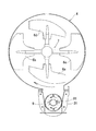
米排出部3は、ケーシング31と、ケーシング31の端部に開口形成された排出口32とを備えている。図3に示す通り、米排出部3は、容器4の軸に対して偏心して配置されている。主パドル6の回転方向により洗米原料がどちらかに偏るので、偏る側にシフトさせて米排出部3が設けられる。
The rice discharge unit 3 includes a
容器4は、略円筒形状のドラムであって、太鼓形状となるように左右端部の底面に傾斜面41が形成されている。底面には開口3aが形成され、ケース31と連通している。回転軸5の外径面には、所定本数(図では4本)のパドル6が、回転軸5の長さ方向に互い違いの位相角度(たとえば90°)及び所定の間隔を置いて、回転軸5の半径方向に取り付けられている。容器4は支持脚46と、排気ダクト47と、を備えている。主パドル6の本数、配置等は適宜変更可能である。
The
図4(a)は、内側の一対の主パドル6b,6cを示し、図4(b)は外側の一対の主パドル6a,6dを示す。主パドル6a,6dが主パドル6b,6cと形状が相違する理由は、傾斜面41に対応させるため、先端面の傾斜を傾斜面41の傾斜に合わせる必要があるからである。パドル6a〜6dは、軸と、軸の先端部に設けたブレードと、を備えたものである。その形状、構造等は種々の態様を含む。
4A shows the inner pair of
攪拌部7は、回転軸5の駆動側ベアリングユニット72と、回転軸5の従動側ベアリングユニット73と、駆動側ベアリングユニット72の外側で回転軸5に連結された駆動モータ75とを備え、駆動側ベアリングユニット72と従動側ベアリングユニット73により支持された回転軸5が回転自在に水平方向に軸着され、主パドル6を回転駆動するように構成している。
The agitating
マルチフィーダ8は、ケーシング31内に同軸状に水平方向に配置された回転軸81と、この回転軸81を支持する軸受82と、この回転軸81の排出口32側の外周面に形成されたスクリュー83と、回転軸81を回転駆動する駆動モータ84と、主パドル6よりも小型の副パドル9と、を備えている。ケーシング31は、上方が開放され有底の断面が逆馬蹄形の米排出部ケース85と、この米排出部ケース85に接続されこれよりも小径の筒部86と、を備えている。ここでは回転軸81は水平であり、回転軸5と平行になっている。この副パドル9は、排出送り部材としてのスクリュー83が固定された回転軸81の容器4中央部側の領域の外径面に設けられ(排出口32から遠い側)、回転軸81及びスクリュー83とともに一体回転するものであり、複数個(ここでは4個)が半径方向に取り付けられている。図2に示す通り、副パドル9はパドル面が排出口32側に向かって所定角度(ここでは垂直に対して30°)に傾斜している。その傾斜角度はこれに限定されず、米を上方に掻き揚げるものであれば、適宜の角度に設定され得る。副パドル9は主パドル6を小型にしたものであり、その大きさは2/1〜1/3以下が好ましい。
The multi-feeder 8 is formed on the outer peripheral surface of the
撹拌部7が容器4内の米を洗米するとき、マルチフィーダ8を逆回転R(図3の時計方向)させ、米排出部3内の米を掻き揚げて容器4内に移送する。米の動きは図6(a)の実線矢印で示す通りである。このとき、主パドル6により容器4の左右端部から中心部に米が集まり、集まった米が中心部から左右端部に拡散するような循環的な流れが形成されることが好ましい。一方、マルチフィーダ8が正回転N(図3の反時計方向)するとき、米排出部3及び容器4内の米を排出し、このとき、米の動きは図6(b)の実線矢印で示す通りである。図6(a)(b)のような米の動きとなるように副パドル9のパドル面の方向及び回転軸81上の配置が設定されている。
When the stirring
このマルチフィーダ8は、洗米補助機能及び定量排出機能を備えている。そのため、洗米機1の構造が簡素化できる。また、洗米機1の高さが低くなることにより米の投入が容易になる。 The multi-feeder 8 has a rice washing auxiliary function and a quantitative discharge function. Therefore, the structure of the rice washer 1 can be simplified. Moreover, the rice can be introduced easily by reducing the height of the rice washing machine 1.
管11から排水管13が分岐されている。管11はここでは容器の形状をしている。管の長さと太さは目的に応じて適宜設定される。管13は管11に接続されていて、管13には弁14が設けてある。また、管11に管15が接続されている。この管15に弁16が設けてある。さらに管13と分岐する管17が設けてある。この管17に弁18が設けてある。管17は管11から直接接続してもよい。弁14,16,18は手動式でも自動式でもいずれでもよい。自動式の場合には、電磁制御弁と、電磁制御弁を駆動制御する制御装置を設けることが好ましい。なお、管15、弁16の設置場所は図示の場所に限定されない。たとえば、管15、弁16を容器4の上部に設けて、管11、管13と弁14、管17、弁18とをそのまま下部に残置し、管15から水を供給し、流水洗米(すすぎ洗いの態様)を行うことも可能である。詳細は実施形態3で説明する。
A
フラップ・バルブ12は、図5に示す通り、軸12aと、軸12aに軸着された枠材12bと、枠材12bに張設された網12cと、を備えたフラップ構造の弁であり、図1の矢印に示す通り、フラップ・バルブ12は所定範囲の角度(たとえば90°)で回動できるようになっていて、排出口32を開閉する。
As shown in FIG. 5, the
なお、米排出部3には、混合気発生部を接続し、上流端部が空気輸送ラインと接続されてもよく、上流側から供給された圧力空気と、マルチフィーダ8の排出口から落下する米とを混合して混合気を生成し、この混合気を下流に排出するようにしてもよい。マルチフィーダ8にロータリーバルブのようなエアロック機能はないので、圧送式空気輸送する場合には、マルチフィーダ8の下にエアロック機能を備えたロータリーバルブ等が必要である。ただし、吸引式空気輸送を行うときにエアロック機能は不要である。 The rice discharge unit 3 may be connected to an air-fuel mixture generation unit, and the upstream end may be connected to an air transport line. The rice discharge unit 3 falls from the pressure air supplied from the upstream side and the discharge port of the multi-feeder 8. A mixture may be produced by mixing with rice, and the mixture may be discharged downstream. Since the multi-feeder 8 does not have an air lock function like a rotary valve, a rotary valve or the like provided with an air lock function is required under the multi-feeder 8 in the case of pressure-type pneumatic transportation. However, the air lock function is not necessary when performing suction pneumatic transportation.
次に、本実施形態の洗米機1の動作について説明する。この洗米機1は、炊飯工場あるいは米粉工場等において各種の米を洗米するものである。 Next, operation | movement of the rice washing machine 1 of this embodiment is demonstrated. The rice washing machine 1 is for washing various kinds of rice in a rice cooking factory or a rice flour factory.
実施形態の洗米機1の洗米をするときには、まず、フラップ・バルブ12が垂直状態となり、米排出部3の開口32を閉じる。つぎに米供給部2から米を投入し、弁14、弁18を閉じ、弁16を開けて、管15、管11、排出口32を経て、水を容器4に供給して、容器4内に水を満たす。駆動モータ75を駆動し、駆動側ベアリングユニット72と従動側ベアリングユニット73に支持されている回転軸5が回転を始めるとともに、駆動モータ84も逆回転R(図3参照)を開始し、軸受82により支持されている回転軸81が逆回転Rを開始する。これにより、図6(a)に示す通り、容器4内の内部の主パドル6が回転して米の水中での攪拌が開始され洗米が行われるとともに、副パドル9により撹拌の補助が行われる。副パドル9は米排出部ケース85内で米を排出方向とは反対方向に戻すとともに、米を容器4へ掻き揚げ、米に上方への推進力を与えることができ、また一方、容器4内の米が米排出部ケース85に戻ることができるので、好適な循環が行われ、パドル6による洗米への補助機能が有効に働き、攪拌能力が格段に高まる。副パドル9を設けた回転軸81と同軸上に設けたスクリュー83も逆回転し、米を排出方向(排出口32側)と反対方向に戻すこととなる。つまり、ゲートが閉じた状態となり、米の排出が阻止される。なお、副パドル9の回転速度が大きくなれば上方への掻き揚げ推進力が増大する。網12cにより米の流出は阻止される。なお、水量は弁14,16の操作により適宜調整される。
When washing the rice washer 1 of the embodiment, first, the
洗米後、弁16を閉じ、弁14を開けて、容器4内の水を管11、管13を経て外部に所定水量を排水し、弁14を閉じて、所定時間、米を水に浸漬することもできる。このとき、弁14と弁16を操作して新たに水を容器4に追加してもよい。また、適宜、容器4内の水を入れ替えてもよい。米の浸漬時間、米の浸漬水量は、米の種類、米の用途(炊飯、粉砕等)に応じて適宜変更できる。浸漬むらのないように、回転軸5を洗米時の速度よりも低速で回転させたり、回転停止させたり、あるいは、所定または適宜の時間間隔でパドル6a〜6dを回転させてもよい。
After washing, the
上記の浸漬が終了すると、弁15、18を閉じた状態とし弁14を開放し管11、管13から水を排出する。この排水を停止し、米の表面の強制的な表面乾操をすることが好ましい。これは米の輸送などのハンドリングが容易に行われるようにするためである。表面乾燥をするときには、弁16を開け、弁14、18を閉じて、温風を容器4に送り込むとともに回転軸5を回転させることで、温風とパドル6の回転により、米の表面の水分を飛ばし、米を適度の乾燥状態にできる。米の製粉に適用する場合、洗米後の表面乾燥は米の表面水分を切ることが目的であり、米内部の水分を除去するわけではない。なお、副パドル9の回転速度は、たとえば表面乾燥時の回転速度を洗米時の回転速度よりも遅くするなど、回転速度を相違させてもよい。
When the above immersion is completed, the
このような処理が終了すると、図6(b)に示す通りフラップ・バルブ12を90°回動させて水平状態とする。弁14,16を閉じ、弁18を開く。そして、駆動モータ84を逆回転Rから正回転N(図3参照)に切り替える。そうすると、ゲートが開いた状態となり、米は排出口32の方向に移送され、排出口32、管11、管17を経て定量的に排出される。ここでは管11内で垂直方向に自重で米が落下するようになっている。管11の先端部は断面が狭くなっている。基本的に、排出時には主パドル6を回転させて米の排出を促進する。このように米が容器4から開口3aを経て、副パドル9とスクリュー83により、排出口32側に移送されることで洗米後の米が下流側に排出される。但し、主パドル6も副パドル9も洗米時と排出時において、回転速度を変えることは十分に有り得る。たとえば、副パドル9の回転速度は、洗米時の回転速度を排出時の回転速度よりも早くすることが好ましい。
When such processing is completed, the
なお、本実施形態では、洗米、浸漬、表面乾燥の動作を繰り返し行うバッチ式を採用している。 In addition, in this embodiment, the batch type which repeats the operation | movement of rice washing, immersion, and surface drying is employ | adopted.
本実施形態の洗米機1は以下の効果を奏する。 The rice washer 1 of this embodiment has the following effects.
(1)米排出部3のマルチフィーダ8に、洗米補助機能及び排出機能の複数の機能を付与でき、装置を簡素化できる。また、主パドル6による米の洗米中は、マルチフィーダ8が逆回転するので、米排出部ケース85内の米が容器4に掻き揚げられて米排出部ケース85内に留まることを防止でき、洗米されない或いは洗米不十分の米が製品に混入することがなくなるので、洗米の品質を向上させる。洗米された米を製粉機に供給する場合には、製粉の品質が高くなる。なおかつ、副パドル9が主パドル6の洗米補助を行うので洗米効率が高くなる。
(1) The multi-feeder 8 of the rice discharge unit 3 can be provided with a plurality of functions of a rice washing auxiliary function and a discharge function, and the apparatus can be simplified. Further, since the multi-feeder 8 rotates in reverse during the washing of rice by the main paddle 6, it is possible to prevent the rice in the rice
(2)米排出部3を小型化できる。マルチフィーダ8が容器4の下部に一体に備えられたことで、装置の高さを低くでき、米の投入作業が容易になる。
(2) The rice discharge part 3 can be reduced in size. Since the multi-feeder 8 is integrally provided at the lower portion of the
(3)洗米、浸漬、表面乾燥の複数の機能を1つの洗米機1に備え、バッチ方式により操作できるので、装置を小型化・簡素化するとともに、作業効率を向上させ、管理コストを大幅に削減し、清掃作業も容易にできる。管11に水だけでなく温風も供給できるので、管内が乾燥しカビ等の発生を防止でき、清潔である。
(3) The rice washing machine 1 is equipped with multiple functions of rice washing, dipping, and surface drying, and can be operated in a batch mode, thus miniaturizing and simplifying the equipment, improving work efficiency, and greatly increasing management costs. Reduction and easy cleaning work. Since not only water but also warm air can be supplied to the
(4)浸漬後、強制的に米を表面乾燥することで米の表面付着水分を飛ばすことができるので、米粉砕装置(米粉製造装置)など、下流の工程に至るまでのハンドリング(輸送等)が容易になる。 (4) Because the surface moisture of rice can be removed by forcing the surface to dry after immersion, handling up to downstream processes such as rice crushing equipment (rice flour production equipment) (transportation, etc.) Becomes easier.
次に、本発明の実施形態2である洗米機101について図7を参照して説明する。この洗米機101は洗米機1と概ね構成は同様であるので、共通部分については説明を援用し、相違点を説明する。この洗米機101は洗米機1のスクリュー83に代えて、副パドル9と同様の構造の送りパドル183を複数個設けたものである。副パドル109と送りパドル183の送り方向は同じである。
Next, the
次に、本発明の実施形態3である洗米機201について図8、図9を参照して説明する。この洗米機201は洗米機1と概ね構成は同様であるので、共通部分については説明を援用し、相違点を説明する。洗米機201は、図8に示す通り、温風機能のみを持つ管215を管211に接続し、水供給機能は図9に示す通り、位置を変更した管215、215´によって行ってもよい。図9に示す通り、水及び/又は温風を供給する管215と弁216とをケース231に設けてもよい。また、水及び/又は温風を供給する管215´と弁216´とを容器204に設けてもよい。水を管215と弁216(または管215´と弁216´)により供給する場合には、バッチ式洗米に代えて、フロー式洗米(流水洗米)などを行うことができる。
Next, the
なお、本発明は、上述の実施形態に限定されるものではなく、本発明の技術的思想を逸脱しない範囲において、改変等を加えることが出来るものであり、それらの改変、均等物等も本発明の技術的範囲に含まれることとなる。 The present invention is not limited to the above-described embodiment, and modifications and the like can be made without departing from the technical idea of the present invention. It will be included in the technical scope of the invention.
本発明は、米製粉工場、炊飯所、酒造所等にて利用される。 The present invention is used in rice mills, rice cookers, breweries and the like.
1…洗米機
2…米供給部
3…米排出部
3a…開口
31…ケーシング
32…排出口
4…容器
41…傾斜面
46…支持脚
47…排気ダクト
5…回転軸
6…主パドル(攪拌羽根)
6b,6c…主パドル
6a,6d…主パドル
7…攪拌部
72…駆動側ベアリングユニット
73…従動側ベアリングユニット
75…駆動モータ
8…マルチフィーダ(フィーダ)
81…回転軸
82…軸受
83…スクリュー(排出送り部材)
84…駆動モータ
85…米排出部ケース
86…筒部
9…副パドル(排出送り部材)
N…正回転
R…逆回転
11…管
12…フラップ・バルブ
12a…軸
12b…板材
12c…網
11…管
13…排水管
17…管
14,16,18…弁
DESCRIPTION OF SYMBOLS 1 ...
6b, 6c ...
81 ... Rotating
84 ... Drive
N ... Forward rotation R ...
Claims (2)
前記容器内に設けられ、回転軸と、該回転軸に固定された攪拌羽根と、を有する攪拌部と、
前記米排出部に設けられ、回転軸と、該回転軸に固定される排出送り部材とを有し、正逆回転するフィーダと、
を備え、
前記排出送り部材が、前記フィーダの前記回転軸に設けられ一体回転する、前記攪拌羽根よりも小型のパドルを備え、
前記フィーダを逆回転させ、前記米排出部内の米を上部に掻き揚げて前記容器内に移送することにより前記洗米の補助を行う機能と、前記フィーダが正回転するとき、前記容器及び米排出部内の米を定量排出する機能と、を備えることを特徴とする洗米機。 A container for washing rice with a rice supply unit and a rice discharge unit;
A stirring section provided in the container and having a rotating shaft and a stirring blade fixed to the rotating shaft;
A feeder provided in the rice discharge portion, having a rotation shaft and a discharge feed member fixed to the rotation shaft;
With
The discharge feed member is provided on the rotary shaft of the feeder and rotates integrally therewith, and includes a paddle smaller than the stirring blade,
The function of assisting the washing of the rice by rotating the feeder in reverse, the rice in the rice discharge part being lifted up and transferred into the container, and when the feeder rotates in the forward direction in the container and the rice discharge part And a function of quantitatively discharging rice.
Priority Applications (1)
| Application Number | Priority Date | Filing Date | Title |
|---|---|---|---|
| JP2009205035A JP5328036B2 (en) | 2009-09-04 | 2009-09-04 | Rice washing machine |
Applications Claiming Priority (1)
| Application Number | Priority Date | Filing Date | Title |
|---|---|---|---|
| JP2009205035A JP5328036B2 (en) | 2009-09-04 | 2009-09-04 | Rice washing machine |
Publications (2)
| Publication Number | Publication Date |
|---|---|
| JP2011050933A JP2011050933A (en) | 2011-03-17 |
| JP5328036B2 true JP5328036B2 (en) | 2013-10-30 |
Family
ID=43940524
Family Applications (1)
| Application Number | Title | Priority Date | Filing Date |
|---|---|---|---|
| JP2009205035A Expired - Fee Related JP5328036B2 (en) | 2009-09-04 | 2009-09-04 | Rice washing machine |
Country Status (1)
| Country | Link |
|---|---|
| JP (1) | JP5328036B2 (en) |
Families Citing this family (1)
| Publication number | Priority date | Publication date | Assignee | Title |
|---|---|---|---|---|
| JP5646491B2 (en) * | 2009-09-04 | 2014-12-24 | 株式会社ツカサ | Powder and agitation equipment |
Family Cites Families (5)
| Publication number | Priority date | Publication date | Assignee | Title |
|---|---|---|---|---|
| JPH06262094A (en) * | 1993-03-12 | 1994-09-20 | Koresawa Tekkosho:Kk | Dry-type rice washing device of cereals |
| JPH09238609A (en) * | 1996-03-06 | 1997-09-16 | Nippon Kiyaria Kogyo:Kk | Material-taking out device in mixer |
| JPH11179311A (en) * | 1997-12-22 | 1999-07-06 | Masatake Akagawa | Underwater cleaner |
| JP4327990B2 (en) * | 2000-05-23 | 2009-09-09 | 京豊エンジニアリング株式会社 | Rice washing equipment |
| JP4016131B2 (en) * | 2002-06-19 | 2007-12-05 | 株式会社オオヤマフーズマシナリー | Rice washing equipment |
-
2009
- 2009-09-04 JP JP2009205035A patent/JP5328036B2/en not_active Expired - Fee Related
Also Published As
| Publication number | Publication date |
|---|---|
| JP2011050933A (en) | 2011-03-17 |
Similar Documents
| Publication | Publication Date | Title |
|---|---|---|
| JP5646491B2 (en) | Powder and agitation equipment | |
| CN111408575B (en) | Grain processing device | |
| KR20150074870A (en) | Apparatus to wash and mature grains | |
| CN108144491A (en) | A kind of aquatic ecological restoration device | |
| JP5328036B2 (en) | Rice washing machine | |
| CN206996346U (en) | Can Rapid Cleaning full-automatic mixing device | |
| CN106819061B (en) | Screw meat cleaning machine | |
| JP2004344761A (en) | Rice washing operation finishing method, and rice washing device | |
| CN102631961B (en) | Flushing dampener | |
| CN214809996U (en) | Prevent remaining double-shaft mixer for feed processing | |
| CN108115838B (en) | A kind of concrete mixing equipment | |
| JP5328035B2 (en) | Rice washing machine | |
| CN212093484U (en) | Forage belt cleaning device for aquaculture fodder | |
| CN210675355U (en) | Grinding machine for drying rice | |
| CN205547149U (en) | Novel highland barley fine dried noodle machine | |
| CN205040626U (en) | Sesame washing system | |
| CN210532907U (en) | High-efficient bipyramid gyration vacuum drying machine | |
| KR101212187B1 (en) | Grain steaming device | |
| CN206535817U (en) | A kind of workpiece oil removing epithelium production line | |
| CN112191130A (en) | Automatic batching device for biological feed production | |
| CN111359492A (en) | Mixer for multi-alloy casting and working method thereof | |
| CN210993887U (en) | Efficient feed mixing device | |
| CN220589730U (en) | Mixing kettle | |
| CN220153149U (en) | Machine-made sand drying device | |
| CN217251122U (en) | Processing device for wheat flour production |
Legal Events
| Date | Code | Title | Description |
|---|---|---|---|
| A621 | Written request for application examination |
Free format text: JAPANESE INTERMEDIATE CODE: A621 Effective date: 20120827 |
|
| A977 | Report on retrieval |
Free format text: JAPANESE INTERMEDIATE CODE: A971007 Effective date: 20130627 |
|
| TRDD | Decision of grant or rejection written | ||
| A01 | Written decision to grant a patent or to grant a registration (utility model) |
Free format text: JAPANESE INTERMEDIATE CODE: A01 Effective date: 20130717 |
|
| A61 | First payment of annual fees (during grant procedure) |
Free format text: JAPANESE INTERMEDIATE CODE: A61 Effective date: 20130722 |
|
| R150 | Certificate of patent or registration of utility model |
Ref document number: 5328036 Country of ref document: JP Free format text: JAPANESE INTERMEDIATE CODE: R150 Free format text: JAPANESE INTERMEDIATE CODE: R150 |
|
| R250 | Receipt of annual fees |
Free format text: JAPANESE INTERMEDIATE CODE: R250 |
|
| R250 | Receipt of annual fees |
Free format text: JAPANESE INTERMEDIATE CODE: R250 |
|
| LAPS | Cancellation because of no payment of annual fees |