JP5327004B2 - Liquid ejector - Google Patents
Liquid ejector Download PDFInfo
- Publication number
- JP5327004B2 JP5327004B2 JP2009255793A JP2009255793A JP5327004B2 JP 5327004 B2 JP5327004 B2 JP 5327004B2 JP 2009255793 A JP2009255793 A JP 2009255793A JP 2009255793 A JP2009255793 A JP 2009255793A JP 5327004 B2 JP5327004 B2 JP 5327004B2
- Authority
- JP
- Japan
- Prior art keywords
- liquid
- ink
- flow rate
- time
- sedimentation
- Prior art date
- Legal status (The legal status is an assumption and is not a legal conclusion. Google has not performed a legal analysis and makes no representation as to the accuracy of the status listed.)
- Expired - Fee Related
Links
- 239000007788 liquid Substances 0.000 title claims abstract description 252
- 238000007599 discharging Methods 0.000 claims description 9
- 238000004062 sedimentation Methods 0.000 abstract description 87
- 238000005259 measurement Methods 0.000 abstract description 10
- 230000003247 decreasing effect Effects 0.000 abstract 1
- 238000004140 cleaning Methods 0.000 description 81
- 230000008030 elimination Effects 0.000 description 27
- 238000003379 elimination reaction Methods 0.000 description 27
- 238000000034 method Methods 0.000 description 23
- 230000008569 process Effects 0.000 description 19
- 239000000049 pigment Substances 0.000 description 15
- 238000002347 injection Methods 0.000 description 12
- 239000007924 injection Substances 0.000 description 12
- 230000005484 gravity Effects 0.000 description 9
- 238000001035 drying Methods 0.000 description 8
- 238000012423 maintenance Methods 0.000 description 8
- 238000011010 flushing procedure Methods 0.000 description 7
- 238000010586 diagram Methods 0.000 description 5
- 239000002904 solvent Substances 0.000 description 5
- 230000006866 deterioration Effects 0.000 description 4
- LFQSCWFLJHTTHZ-UHFFFAOYSA-N Ethanol Chemical compound CCO LFQSCWFLJHTTHZ-UHFFFAOYSA-N 0.000 description 3
- 230000007246 mechanism Effects 0.000 description 3
- 238000001556 precipitation Methods 0.000 description 3
- 239000002699 waste material Substances 0.000 description 3
- XLYOFNOQVPJJNP-UHFFFAOYSA-N water Substances O XLYOFNOQVPJJNP-UHFFFAOYSA-N 0.000 description 3
- 230000000694 effects Effects 0.000 description 2
- 238000012545 processing Methods 0.000 description 2
- 239000004094 surface-active agent Substances 0.000 description 2
- 238000011144 upstream manufacturing Methods 0.000 description 2
- 230000009471 action Effects 0.000 description 1
- 239000000654 additive Substances 0.000 description 1
- 230000000996 additive effect Effects 0.000 description 1
- 230000002411 adverse Effects 0.000 description 1
- 238000013459 approach Methods 0.000 description 1
- 230000008859 change Effects 0.000 description 1
- 239000003086 colorant Substances 0.000 description 1
- 238000004040 coloring Methods 0.000 description 1
- 230000003111 delayed effect Effects 0.000 description 1
- 238000009792 diffusion process Methods 0.000 description 1
- 239000000975 dye Substances 0.000 description 1
- 239000004615 ingredient Substances 0.000 description 1
- 239000004973 liquid crystal related substance Substances 0.000 description 1
- 239000000463 material Substances 0.000 description 1
- 239000002244 precipitate Substances 0.000 description 1
- 230000009467 reduction Effects 0.000 description 1
- 239000013049 sediment Substances 0.000 description 1
- 239000000243 solution Substances 0.000 description 1
- 239000007921 spray Substances 0.000 description 1
- 238000003756 stirring Methods 0.000 description 1
- 238000012360 testing method Methods 0.000 description 1
- 230000008719 thickening Effects 0.000 description 1
Images


Abstract
Description
本発明は、噴射ノズルから液体を噴射する技術に関する。 The present invention relates to a technique for ejecting liquid from an ejection nozzle.
微細な噴射ノズルが設けられた噴射ヘッドから、液体を噴射する液体噴射装置が知られ
ている。この液体噴射装置では、噴射しようとする液体(たとえばインク)を専用の容器
(たとえばインクカートリッジ)に収容しておき、この容器内の液体を、液体通路(たと
えばインクチューブ)を介して噴射ヘッドに供給することによって噴射している。
A liquid ejecting apparatus that ejects liquid from an ejecting head provided with a fine ejecting nozzle is known. In this liquid ejecting apparatus, a liquid (for example, ink) to be ejected is stored in a dedicated container (for example, an ink cartridge), and the liquid in the container is transferred to the ejecting head via a liquid passage (for example, an ink tube). Injecting by supplying.
また、噴射しようとする液体の成分には、沈降性の成分が使用されることがある。たと
えばインクの場合であれば、いわゆる耐候性を高めたり、あるいは発色性を改善したりす
るなどの目的で顔料が用いられることがある。顔料は、インクの溶媒(水やアルコールな
ど)には溶けずに懸濁した状態で存在しているので、インクを長期間放置していると溶媒
中で比重の大きい顔料が沈降する。その結果、噴射ヘッド内やインクチューブ内のインク
に顔料濃度の濃い部分と薄い部分とが生じて、画像等を適切に印刷することができなくな
ってしまう。
Moreover, a sedimentary component may be used for the component of the liquid to be ejected. For example, in the case of ink, a pigment may be used for the purpose of improving so-called weather resistance or improving color developability. Since the pigment exists in a suspended state without being dissolved in the ink solvent (water, alcohol, etc.), the pigment having a large specific gravity precipitates in the solvent if the ink is left for a long period of time. As a result, a portion having a high pigment concentration and a portion having a thin pigment concentration are generated in the ink in the ejection head or the ink tube, and an image or the like cannot be printed appropriately.
そこで、顔料などの沈降性の成分を含有するインクを使用するインクジェットプリンタ
ーでは、所定時間が経過することによって噴射ヘッド内やインクチューブ内のインクに沈
降が発生したと判断されると、噴射ノズルからインクを吸引して、沈降が進んだインクを
排出する技術が提案されている(特許文献1)。
Therefore, in an ink jet printer that uses ink containing a sedimentation component such as a pigment, if it is determined that sedimentation has occurred in the ink in the ejection head or ink tube after a predetermined time has passed, A technique has been proposed in which ink is sucked and ink that has settled out is discharged (Patent Document 1).
しかし、提案されている技術では、次のような理由から、必要以上に噴射ノズルから液
体(インクなど)を排出することがあるという問題があった。先ず、噴射ヘッド内や、噴
射ヘッドに液体を供給する液体通路(インクチューブなど)内で生じる液体成分の沈降は
、時間とともに進行し続けるだけでなく、何らかの力が作用して液体が撹拌されるなどに
より沈降が回復したり、あるいは沈降の進行が抑制されたりすることがある。そして、こ
うしたことを全く考慮することなく、所定時間の経過により噴射ノズルから画一的に液体
を吸引したのでは、沈降がほとんど進行していない場合にも、液体を排出することになる
。結果として、多量の液体が無駄になってしまうおそれがある。
However, the proposed technique has a problem in that liquid (such as ink) may be discharged from the ejection nozzle more than necessary for the following reasons. First, sedimentation of the liquid component that occurs in the ejection head or in a liquid passage (such as an ink tube) that supplies liquid to the ejection head not only continues with time, but some force acts to stir the liquid. For example, sedimentation may be recovered or the progress of sedimentation may be suppressed. Then, without taking this into consideration at all, if the liquid is uniformly sucked from the ejection nozzle over a predetermined time, the liquid is discharged even when the sedimentation hardly proceeds. As a result, a large amount of liquid may be wasted.
この発明は、従来の技術が有する上述した課題を解決するためになされたものであり、
噴射しようとする液体中で含有成分の沈降が生じる場合に、沈降を解消するための液体の
排出が必要以上に行われることを防止可能な技術の提供を目的とする。
The present invention has been made to solve the above-described problems of the prior art,
An object of the present invention is to provide a technique capable of preventing the discharge of liquid for eliminating sedimentation from being performed more than necessary when sedimentation of contained components occurs in the liquid to be ejected.
上述した課題の少なくとも一部を解決するために、本発明の液体噴射装置は次の構成を採用した。すなわち、噴射ヘッドに設けられた噴射ノズルから、沈降性の成分が含まれる液体を噴射する液体噴射装置であって、前記液体を収容した液体収容部と、前記液体収容部内の液体を前記噴射ヘッドまで導く液体通路と、前記液体通路内の液体の流速が所定流速以上であるか否かを判定する流速判定手段と、前記液体に含まれる前記沈降性の成分が前記噴射ヘッド内あるいは前記液体通路内で沈降することを回避するために、前記噴射ノズルから前記液体を排出する液体排出手段と、前記液体排出手段が前記液体を排出した後に計時を開始して、前記液体通路内の液体の流速が前記所定流速に達していない時間である低流速時間を取得する低流速時間取得手段とを備え、前記液体排出手段は、取得された前記低流速時間の長さに応じて、前記噴射ノズルからの前記液体の排出状態を変化させる手段であることを要旨とする。 In order to solve at least a part of the problems described above, the liquid ejecting apparatus of the present invention employs the following configuration. That is, a liquid ejecting apparatus that ejects a liquid containing a sedimentary component from an ejecting nozzle provided in an ejecting head, the liquid accommodating part accommodating the liquid, and the liquid in the liquid accommodating part. A liquid passage leading to the liquid passage, a flow rate determination means for determining whether or not a flow velocity of the liquid in the liquid passage is equal to or higher than a predetermined flow velocity, and the settling component contained in the liquid is contained in the ejection head or the liquid passage In order to avoid settling in the liquid, the liquid discharge means for discharging the liquid from the injection nozzle, and the liquid flow rate of the liquid in the liquid passage is started after the liquid discharge means discharges the liquid. There a low flow time acquiring means for acquiring the low flow time is not no time reached a predetermined flow rate, the liquid discharge means, depending on the length of the acquired said low flow time, the injection And summarized in that a means for changing the discharge condition of liquid from the nozzle.
このような本発明の液体噴射装置においては、沈降性の成分が含まれる液体を収容した
液体収容部から液体通路を介して噴射ヘッドに液体を供給し、噴射ヘッドに設けられた噴
射ノズルから液体を噴射する。こうした液体の噴射によって液体通路内には液体の流れが
生じることから、その液体の流速が所定流速以上であるか否かを判定する。また、液体に
含まれる沈降性の成分は噴射ヘッド内や液体通路内で沈降するので、これに回避するため
に、噴射ノズルからの液体の排出を行う。さらに、噴射ノズルから液体を排出したら計時
を開始して、液体通路内の液体の流速が所定流速に達していない時間(低流速時間)を取
得する。そして、噴射ノズルからの液体の排出は、取得した低流速時間を考慮して行うよ
うになっている。
In such a liquid ejecting apparatus of the present invention, the liquid is supplied to the ejecting head through the liquid passage from the liquid accommodating portion containing the liquid containing the sedimentary component, and the liquid is ejected from the ejecting nozzle provided in the ejecting head. Inject. Since such a liquid jet causes a liquid flow in the liquid passage, it is determined whether or not the flow velocity of the liquid is equal to or higher than a predetermined flow velocity. Moreover, since the sedimentation component contained in the liquid settles in the ejection head or the liquid passage, the liquid is ejected from the ejection nozzle in order to avoid this. Further, when the liquid is discharged from the injection nozzle, the time measurement is started, and the time during which the flow rate of the liquid in the liquid passage does not reach the predetermined flow rate (low flow rate time) is acquired. The liquid is discharged from the injection nozzle in consideration of the acquired low flow rate time.
ここで、「噴射」と「排出」とは、噴射ノズルから液体を出すという点では共通するも
のの、本明細書における「噴射」とは、液体噴射装置の本来の目的に即して噴射ノズルか
ら液体を出すことをいい、これに対して「排出」とは、液体噴射装置の本来の目的ではな
く、液体中の沈降性の成分が噴射ヘッド内や液体通路内で沈降することを回避するために
噴射ノズルから液体を出すことをいうものとする。
Here, “injection” and “discharge” are common in that the liquid is discharged from the injection nozzle, but “injection” in this specification refers to the injection from the injection nozzle in accordance with the original purpose of the liquid injection device. In contrast, the term “discharge” is not the original purpose of the liquid ejecting apparatus, but to prevent sedimentation of the liquid in the ejecting head or liquid passage. In this case, the liquid is ejected from the spray nozzle.
経験上、液体通路内をある程度の速さで液体が流れていれば、液体に含まれる沈降性の
成分の沈降は抑制されることが知られている。本明細書における「所定流速」とは、この
ように沈降が抑制される速さで液体が流れているか否かを判断する基準となる流速である
。したがって、前回に液体を排出してからの経過時間が同じであっても、その間に液体通
路内を所定流速以上の速さで液体が流れていたことがあれば、所定流速以上の速さで液体
が流れたことが全くないときに比べて、液体通路内の液体中で沈降性の成分の沈降は進ん
でいない。にもかかわらず、前回に液体を排出してからの間に液体通路内を液体が所定流
速以上で流れていたことがあるか否かに関係なく、噴射ノズルからの液体を排出したので
は、液体通路内で沈降が進んでいない場合にも噴射ノズルから液体を排出することになっ
てしまう。こうした点に鑑み、本発明の液体噴射装置では、前回の液体の排出からの経過
時間ではなく、液体通路内の液体の流速が所定流速に達していない時間である低流速時間
(すなわち経過時間から、液体通路内を液体が所定流速以上で流れていた時間を除いた時
間)を考慮して、液体の排出を行う。これにより、液体通路内を所定流速以上で液体が流
れていたことがあれば、その分だけ、所定流速以上で液体が流れたことがないときに比べ
て、液体通路内で沈降は進行していないものとして、必要以上に液体を排出してしまうこ
とを防止することが可能となる。その結果、液体噴射装置の本来の目的に使用されること
なく排出される液体の量を減らすことができる。
From experience, it is known that if the liquid flows in the liquid passage at a certain speed, the sedimentation of the sedimentary component contained in the liquid is suppressed. The “predetermined flow rate” in this specification is a flow rate that serves as a reference for determining whether or not the liquid is flowing at such a speed that sedimentation is suppressed. Therefore, even if the elapsed time from the previous discharge of the liquid is the same, if the liquid has flowed in the liquid passage at a speed higher than the predetermined flow rate during that time, the speed is higher than the predetermined flow speed. Compared to the case where the liquid has never flowed, the sedimentation of the sedimentary component does not proceed in the liquid in the liquid passage. Nevertheless, regardless of whether or not the liquid has been flowing in the liquid passage at a predetermined flow rate or more during the previous discharge of the liquid, the liquid from the injection nozzle is discharged, Even when settling does not proceed in the liquid passage, the liquid is discharged from the injection nozzle. In view of these points, in the liquid ejecting apparatus of the present invention, not the elapsed time from the previous liquid discharge, but the low flow velocity time (that is, from the elapsed time) that is the time during which the flow velocity of the liquid in the liquid passage does not reach the predetermined flow velocity. The liquid is discharged in consideration of the time excluding the time during which the liquid is flowing in the liquid passage at a predetermined flow rate or higher. As a result, if the liquid has flowed in the liquid passage at a predetermined flow velocity or higher, the sedimentation has progressed in the liquid passage by that amount compared to the case where the liquid has not flowed at the predetermined flow velocity or higher. As a result, it is possible to prevent the liquid from being discharged more than necessary. As a result, the amount of liquid discharged without being used for the original purpose of the liquid ejecting apparatus can be reduced.
尚、「所定流速」としては、例えば、液体通路の通路方向が鉛直方向を向いた領域で、
下から上と液体が流れることで沈降性の成分を噴射ヘッドに向けて流すことが可能な流速
としたり、あるいは、液体通路内を流れる液体の最大流速を基準に、その20%程度の流
速としたりすることができる。液体通路内の液体の流速は、簡易的には、噴射ノズルから
液体を噴射している時間(噴射時間)と、その噴射時間内に噴射する液体量とに基づいて
取得することができる。もちろん、液体を噴射している噴射ノズルの数と、各噴射ノズル
で噴射する液体量とに基づいて刻々と変化する流速を算出することも可能である。また、
「液体の排出を、低流速時間を考慮して行う」とは、例えば、低流速時間の長さに応じて
、排出する液体の量を変化させたり、あるいは、低流速時間が予め定められた一定時間に
達することを契機に液体を排出することによって、液体の排出を行うタイミングを調節し
たりすることなどを挙げることができる。
In addition, as the “predetermined flow velocity”, for example, in a region where the passage direction of the liquid passage is directed in the vertical direction,
The flow rate is such that the liquid flows from the bottom to the top so that the sedimentary component can flow toward the jet head, or the flow rate is about 20% of the maximum flow rate of the liquid flowing in the liquid passage. Can be. The flow rate of the liquid in the liquid passage can be simply obtained based on the time during which the liquid is ejected from the ejection nozzle (ejection time) and the amount of liquid ejected within the ejection time. Of course, it is also possible to calculate a flow rate that changes every moment based on the number of ejection nozzles ejecting liquid and the amount of liquid ejected by each ejection nozzle. Also,
“The liquid is discharged in consideration of the low flow rate time” means that, for example, the amount of liquid to be discharged is changed according to the length of the low flow rate time, or the low flow rate time is predetermined. For example, the timing of discharging the liquid can be adjusted by discharging the liquid when the predetermined time is reached.
上述した本発明の液体噴射装置においては、所定流速を、液体に含まれる沈降性の成分
が沈降する速度(沈降速度)と同じ大きさに設定しておいてもよい。
In the liquid ejecting apparatus of the present invention described above, the predetermined flow rate may be set to the same magnitude as the speed (sedimentation speed) at which the sedimentary component contained in the liquid settles.
液体通路の通路方向が略鉛直方向に向いた領域(鉛直領域)において、液体が下から上
へと流れる場合には、液体が流れる方向と、液体に含まれる沈降性の成分の沈降方向(上
から下)とがちょうど逆方向になる。したがって、液体通路内を流れる液体の流速が沈降
性の成分の沈降速度よりも大きければ、液体通路の鉛直領域では沈降性の成分の沈降が進
まなくなる。そこで、所定流速を沈降速度と同じ大きさに設定しておくことにより、前回
の液体の排出後に液体通路内を液体が所定流速(すなわち沈降速度)以上で流れていたこ
とがあれば、所定流速以上で流れたことがない場合に比べて、液体通路の鉛直領域で生じ
ている沈降は軽微であると判断して、必要以上に液体を排出してしまうことを防止するこ
とが可能となる。
In a region where the passage direction of the liquid passage is substantially vertical (vertical region), when the liquid flows from the bottom to the top, the direction in which the liquid flows and the settling direction of the settling component contained in the liquid (upper To the bottom) is just the opposite direction. Therefore, if the flow velocity of the liquid flowing in the liquid passage is larger than the settling velocity of the sedimentary component, the sedimentation of the sedimentary component does not progress in the vertical region of the liquid passage. Therefore, by setting the predetermined flow rate to be equal to the settling velocity, if the liquid has flowed in the liquid passage at a predetermined flow velocity (that is, the settling velocity) or more after the previous discharge of the liquid, the predetermined flow velocity is set. It is possible to prevent the liquid from being discharged more than necessary by determining that the sedimentation occurring in the vertical region of the liquid passage is slight as compared with the case where the liquid has never flowed.
また、上述した本発明の液体噴射装置においては、液体を排出してからの経過時間と、
経過時間の計時中に液体通路内を液体が所定流速以上の流速で流れていた時間(高流速時
間)とを計測することにより、低流速時間を取得することとしてもよい。
Further, in the liquid ejecting apparatus of the present invention described above, an elapsed time after discharging the liquid,
The low flow rate time may be acquired by measuring the time during which the liquid has flowed in the liquid passage at a flow rate equal to or higher than the predetermined flow rate during the elapsed time (high flow rate time).
このように、液体を排出してからの経過時間と、その間の高流速時間とをそれぞれ計測
しておけば、経過時間から高流速時間を差し引くだけで簡単に低流速時間を取得できるの
で、低流速時間を考慮した液体の排出を容易に実現することが可能となる。
In this way, by measuring the elapsed time since the liquid was discharged and the high flow rate time between them, the low flow rate time can be easily obtained by simply subtracting the high flow rate time from the elapsed time. It is possible to easily realize the liquid discharge considering the flow rate time.
あるいは、前述した本発明の液体噴射装置においては、液体を排出した後、液体通路内
の液体の流速が所定流速に達していない時間を計時することにより、低流速時間を取得す
ることとしてもよい。
Alternatively, in the liquid ejecting apparatus of the present invention described above, the low flow rate time may be acquired by counting the time during which the flow rate of the liquid in the liquid passage does not reach the predetermined flow rate after discharging the liquid. .
すなわち、液体を排出したら計時を開始して、液体通路内の液体の流速が所定流速に達
した時点で計時を一旦停止するとともに、液体の流速が所定流速を下回った時点で計時を
再開することで、液体の流速が所定流速に達していない時間(低流速時間)を直接的に取
得することができる。このようにすれば、低流速時間を取得するために計時する時間は1
つだけでよく、2つ以上の時間を同時に計時しなくてよいので、低流速時間を考慮して液
体の排出を行う上で好適である。
That is, when the liquid is discharged, the timing is started, the timing is temporarily stopped when the flow velocity of the liquid in the liquid passage reaches a predetermined flow velocity, and the timing is restarted when the flow velocity of the liquid falls below the predetermined flow velocity. Thus, the time during which the liquid flow rate does not reach the predetermined flow rate (low flow rate time) can be obtained directly. In this way, the time taken to acquire the low flow rate time is 1
Since it is not necessary to measure two or more times at the same time, it is suitable for discharging the liquid in consideration of the low flow rate time.
また、こうした本発明の液体噴射装置においては、低流速時間が長くなるほど、噴射ノズルから多くの液体を排出することとしてもよい。
また、こうした本発明の液体噴射装置においては、低流速時間が予め定められた一定時間に達したときに、噴射ノズルから規定量の液体を排出することとしてもよい。
In such a liquid ejecting apparatus of the present invention, as the low flow rate time becomes longer, more liquid may be discharged from the ejecting nozzle.
In the liquid ejecting apparatus of the present invention, when the low flow rate time reaches a predetermined time, a predetermined amount of liquid may be discharged from the ejecting nozzle.
低流速時間が長時間である場合には、前回に液体を排出してからの経過時間が長く、し
かもその間に液体通路内を所定流速以上の速さで液体があまり流れていないことになる。
そのため、液体通路内の液体では沈降性の成分の沈降が進んでおり、これを解消するには
多くの液体を排出する必要がある。一方、低流速時間が短時間である場合には、前回に液
体を排出してから時間があまり経過していないか、あるいは、経過時間は長いが、その間
に液体通路内を所定流速以上の速さで液体が頻繁に流れていたことになる。前述したよう
に、液体通路内を液体が所定流速よりも速い流速で流れており、液体に含まれる比重の大
きい沈降性の成分も噴射ヘッドに向けて流すことができる場合には、液体通路内の液体中
で生じる沈降性の成分の沈降は抑制される。そのため、低流速時間が短時間であれば、た
とえ経過時間が長くても、液体通路内の沈降は低流速時間が長時間であるときに比べて軽
微なものであり、沈降を解消するのに多くの液体を排出する必要はなく、場合によっては
全く液体を排出する必要がないこともある。そこで、低流速時間が長いほど、多くの液体
を排出する設定としておけば、前回の液体の排出後に液体通路内を所定流速以上の流速で
液体が流れると、その分だけ低流速時間は短いものとなるので、排出する液体の量を減ら
すことが可能となる。
When the low flow rate time is long, the elapsed time since the liquid was discharged last time is long, and in the meantime, the liquid does not flow so much in the liquid passage at a speed higher than the predetermined flow rate.
Therefore, in the liquid in the liquid passage, sedimentation of the sedimentary component proceeds, and in order to eliminate this, it is necessary to discharge a large amount of liquid. On the other hand, when the low flow rate time is short, the time has not passed since the last liquid was discharged, or the elapsed time is long, but during that time, the liquid passage has a speed higher than the predetermined flow rate. Now the liquid was flowing frequently. As described above, when the liquid flows in the liquid passage at a flow rate faster than the predetermined flow velocity, and the sedimentary component having a large specific gravity contained in the liquid can also flow toward the ejection head, the liquid passage Sedimentation of sedimentary components that occur in the liquid is suppressed. Therefore, if the low flow rate time is short, even if the elapsed time is long, the sedimentation in the liquid passage is slight compared with the case where the low flow rate time is long, and the sedimentation is eliminated. It is not necessary to drain a lot of liquid, and in some cases it may not be necessary to drain at all. Therefore, if the setting is made so that more liquid is discharged as the low flow rate time is longer, if the liquid flows in the liquid passage at a flow rate higher than the predetermined flow rate after the previous liquid discharge, the lower flow rate time is shorter. Thus, the amount of liquid to be discharged can be reduced.
また、こうした本発明の液体噴射装置においては、次のようにして液体を排出すること
としてもよい。先ず、噴射ノズルから排出された液体を受ける凹部が形成されているとと
もに、噴射ヘッドに当接することで、噴射ノズルの周囲に閉空間を形成する液体受け部を
設けておく。また、液体受け部の凹部に接続された吸引ポンプを設けておく。そして、液
体受け部を噴射ヘッドに当接した状態で吸引ポンプを作動させることにより、噴射ノズル
から液体を排出するようにしてもよい。
In such a liquid ejecting apparatus of the present invention, the liquid may be discharged as follows. First, a recess for receiving the liquid discharged from the ejection nozzle is formed, and a liquid receiving portion that forms a closed space around the ejection nozzle by contacting the ejection head is provided. In addition, a suction pump connected to the recess of the liquid receiving portion is provided. Then, the liquid may be discharged from the ejection nozzle by operating the suction pump while the liquid receiving portion is in contact with the ejection head.
このような構成によれば、噴射ヘッドの噴射ノズルから液体を噴射していない間は液体
受け部を噴射ヘッドに当接した状態としておくことで、噴射ノズルから液体の乾燥が進む
(液体中の揮発成分が減少する)ことを効果的に抑制することができる。そして、噴射ノ
ズルから液体を排出する際には、液体受け部を噴射ヘッドに当接した状態のまま、吸引ポ
ンプを作動させるだけで、噴射ノズルの周囲の閉空間に負圧を作用させることができ、こ
れにより、噴射ノズルから液体を吸い出すことができる。そのため、噴射ヘッド内や液体
通路内で沈降が進んだ液体を簡単に排出することが可能となる。
According to such a configuration, while the liquid is not ejected from the ejection nozzle of the ejection head, the liquid receiving portion is kept in contact with the ejection head, so that the drying of the liquid proceeds from the ejection nozzle (in the liquid It is possible to effectively suppress a decrease in volatile components. When the liquid is discharged from the ejection nozzle, the negative pressure can be applied to the closed space around the ejection nozzle only by operating the suction pump while keeping the liquid receiving portion in contact with the ejection head. This allows the liquid to be sucked out of the jet nozzle. Therefore, it is possible to easily discharge the liquid that has settled in the ejection head or the liquid passage.
以下では、上述した本願発明の内容を明確にするために、次のような順序に従って実施
例を説明する。
A.装置構成:
B.印刷動作の概要:
C.本実施例の沈降解消クリーニング動作:
Hereinafter, in order to clarify the contents of the present invention described above, examples will be described in the following order.
A. Device configuration:
B. Overview of printing behavior:
C. Settling elimination cleaning operation of this embodiment:
A.装置構成 :
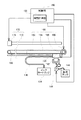
図1は、本実施例の液体噴射装置としてのインクジェットプリンター100を例示した
説明図である。図示したインクジェットプリンター100は、JIS規格のA1判やB1
判などのいわゆる大判サイズの印刷用紙に印刷するラージフォーマットプリンター(LF
P)であるが、A4判やハガキ判などの小さな印刷用紙に印刷する家庭用のプリンターで
あっても構わない。
A. Device configuration :
FIG. 1 is an explanatory diagram illustrating an
Large format printer (LF) that prints on so-called large format printing paper
P), but it may be a home printer that prints on a small printing paper such as an A4 size or a postcard size.
図示されるように、インクジェットプリンター100は、大まかに言うと、本体ケース
110と、本体ケース110の上面側に設けられて印刷用紙が装填される給紙部120と
によって構成されており、本体ケース110の内部には、印刷用紙に向かってインクを噴
射するためのインク噴射部130や、インクの乾燥を防ぐなどインクの状態を管理するた
めのインクメンテナンス部140や、インクジェットプリンター100の全体の動作を制
御する制御部150などが搭載されている。
As shown in the drawing, the
給紙部120は、スピンドル部122や、カバー部124などから構成されている。ス
ピンドル部122は、両端を回転可能に軸支された軸状部材であり、ロール状の印刷用紙
(以下、ロール紙という)が装着される。また、スピンドル部122の両端には、軸方向
に沿って摺動可能なロール紙押さえが設けられており、スピンドル部122に装着された
ロール紙が軸方向に動かないように固定することが可能となっている。更に、スピンドル
部122に装着したロール紙が汚損することを回避するために、跳ね上げ式のカバー部1
24が設けられている。ロール紙をスピンドル部122に装着する際には、カバー部12
4を跳ね上げてスピンドル部122を露出させ、給紙部120から取り出したスピンドル
部122にロール紙を装着する。そして、ロール紙が装着されたスピンドル部122を給
紙部120にセットした後、カバー部124の先端を押し下げるようにしてカバー部12
4を閉じると、スピンドル部122に装着されたロール紙はカバー部124によって覆わ
れる。
The
24 is provided. When the roll paper is mounted on the
4 is flipped up to expose the
When 4 is closed, the roll paper loaded on the
インク噴射部130は、インクを噴射する噴射ヘッド132や、噴射ヘッド132で噴
射するインクが収容されているインクカートリッジ134や、インクカートリッジ134
内のインクを噴射ヘッド132に供給するためのインクチューブ136などによって構成
されている。噴射ヘッド132は、印刷用紙と向き合う側の面に、複数の微細な噴射ノズ
ルが設けられており、噴射ノズルからインクを噴射することによって、印刷用紙上に文字
や画像などを印刷することが可能となっている。尚、噴射ヘッド132の印刷用紙と向き
合う側で、複数の噴射ノズルが形成されている部分の表面は、「ノズル面」と呼ばれてい
る。また、インクジェットプリンター100では、シアンインクや、マゼンタインク、イ
エローインク、ブラックインク、ホワイトインクなどの複数種類のインクが用いられてお
り、インクカートリッジ134や、噴射ヘッド132、インクチューブ136は、インク
の種類毎に設けられているが、図1では、図示が煩雑となることを避けるために、1種類
のインクについてのみ表示されている。
The
The
インクメンテナンス部140は、中央に凹部が形成されたキャップ142や、性状が劣
化したために噴射ヘッド132から排出されたインクを貯めておくための廃インクタンク
144などから構成されている。キャップ142は、図示しない駆動機構によって噴射ヘ
ッド132のノズル面に当接させたり、ノズル面から離間させたりすることが可能となっ
ており、文字や画像などの印刷を行わない間はノズル面に当接されている。こうすること
で、噴射ノズルがキャップ142によって封止され、噴射ノズルからインクが乾燥するこ
とを抑制することができる。それでもインクの乾燥が進むなどしてインクの性状が劣化し
た場合には、噴射ヘッド132の噴射ノズルからキャップ142の凹部に向かってインク
を噴射する動作(フラッシング動作)を行ったり、あるいは噴射ヘッド132のノズル面
にキャップ142を当接したまま、吸引ポンプ(図2参照)を作動させて、キャップ14
2の凹部に負圧を作用させることにより、劣化したインクを噴射ノズルから吸引する動作
(クリーニング動作)を行ったりする。こうして噴射ヘッド132から排出されたインク
は、チューブを介して廃インクタンク144に流入して蓄えられるようになっている。
The
An operation (cleaning operation) of sucking the deteriorated ink from the ejection nozzle is performed by applying a negative pressure to the concave portion 2. The ink discharged from the
また、本体ケース110の上面には、ユーザーがインクジェットプリンター100を操
作するための操作パネル112が設けられている。操作パネル112には、液晶装置など
によって構成される表示画面や、各種の操作ボタンなどが搭載されており、ユーザーは、
表示画面を確認しながら操作ボタンを操作することで、インクジェットプリンター100
を操作することが可能である。
An
By operating the operation buttons while checking the display screen, the
Can be operated.
さらに、図1では図示が省略されているが、本体ケース110の内部には、印刷用紙の
表面に沿って噴射ヘッド132を往復動させるための駆動部や、給紙部120のロール紙
を引き出して紙送りするための紙送り部なども設けられている。
Further, although not shown in FIG. 1, a driving unit for reciprocating the
図2は、噴射ヘッド132を往復動させるための駆動部160や、ロール紙を紙送りす
るための紙送り部170の大まかな構成を示した説明図である。図示されるように駆動部
160は、噴射ヘッド132が往復動する動きをガイドするガイドレール162や、ガイ
ドレール162に沿って噴射ヘッド132を往復動させるための駆動ベルト164や、駆
動ベルト164を張設する一対のプーリー166や、駆動ベルト164を駆動するための
駆動モーター168などから構成されている。駆動ベルト164の一箇所には噴射ヘッド
132が固定されており、駆動モーター168を正方向あるいは負方向に回転させて駆動
ベルト164を駆動すると、ガイドレール162にガイドされながら噴射ヘッド132が
往復動するようになっている。
FIG. 2 is an explanatory diagram showing a rough configuration of a
また、紙送り部170は、ガイドレール162と平行に設けられて、ロール紙を幅方向
に横断する長さを有する長尺の紙送りローラー172や、紙送りローラー172を回転さ
せる紙送りモーター174や、紙送りローラー172に沿って設けられた図示しない従動
ローラーなどから構成されている。給紙部120に装填されたロール紙は、紙送りローラ
ー172の位置まで引き出されて、紙送りローラー172と従動ローラーとの間に一端が
挿入される。するとロール紙は、従動ローラーによって適度な力で紙送りローラー172
に押し付けられた状態となり、この状態で紙送りモーター174を回転させると、紙送り
ローラー172の回転に従って、ロール紙が少しずつ引き出されながら噴射ヘッド132
の方向に紙送りされていく。
The
When the
The paper is fed in the direction of.
これら駆動モーター168や紙送りモーター174の動作は、制御部150によって制
御されている。また、噴射ヘッド132がインクを噴射する動作も、制御部150の制御
の下で行われている。更に、前述したように、噴射ヘッド132のノズル面に当接させる
ためにキャップ142を移動させる動作や、ノズル面にキャップ142を当接した状態で
吸引ポンプ146を作動させて噴射ノズルからインクを吸い出す動作(クリーニング動作
)も、制御部150の制御の下で行われている。このように制御部150は、インクジェ
ットプリンター100で行われるほとんど全ての動作に関わっており、印刷の開始や終了
、あるいはフラッシング動作(キャップ142内へインクを噴射する動作)や、クリーニ
ング動作などが行われると、それらのタイミングを正確に把握することが可能である。こ
のことと対応して、本実施例のインクジェットプリンター100の制御部150には時間
計時部152が搭載されており、この時間計時部152では、印刷を行っている時間(印
刷時間)を計時したり、フラッシング動作やクリーニング動作などが最後に行われてから
の経過時間を計時したりするようになっている。
The operations of the
B.印刷動作の概要 :
図3は、本実施例のインクジェットプリンター100が、噴射ヘッド132を往復動さ
せながら画像等を印刷する様子を概念的に示した説明図である。図3(a)および図3(
b)に示されるように、噴射ヘッド132は、ガイドレール162に沿って往復動しなが
ら、印刷用紙(ロール紙)に向かってインクを噴射することによって画像等を印刷する。
噴射ヘッド132とインクカートリッジ134とは、十分な長さのインクチューブ136
によって接続されており、図示しないインク加圧機構によって、絶えずインクカートリッ
ジ134から噴射ヘッド132にインクが供給されるようになっている。また、印刷を終
了すると、図3(c)に示されるように、噴射ヘッド132をキャップ142の位置まで
移動させ、図示しない駆動機構によってキャップ142を押し上げて噴射ヘッド132の
ノズル面に当接させる。こうすると、噴射ノズルをキャップ142で封止することができ
るので、長時間、印刷を行わない場合でも、噴射ノズルの開口部分からインクの水分や揮
発成分などが蒸発あるいは揮発して、インクの性状が劣化する(インクの粘度が増加する
)ことを抑制することができる。
B. Overview of printing operation:
FIG. 3 is an explanatory diagram conceptually showing how the
As shown in b), the
The
Ink is continuously supplied from the
ここで、噴射ヘッド132をキャップ142の位置まで移動させると、図3(c)に示
したように、インクチューブ136は折りたたまれた状態となる。その結果、噴射ヘッド
132の上流側には、インクチューブ136が略水平になる部分(図中の「A」の部分。
以下、領域Aという)が形成され、領域Aの上流側には、領域Aに比べて、インクチュー
ブ136が鉛直方向に向かう部分(図中の「B」の部分。以下、領域Bという)が形成さ
れることになる。尚、図3(c)では、噴射ヘッド132に隣接して領域Aが形成され、
領域Aに隣接して領域Bが形成されているものとして表示しているが、噴射ヘッド132
と領域A、あるいは領域Aと領域Bとは必ずしも隣接している必要はなく、間に何某かの
緩衝領域が形成されていても良い。
When the
Hereinafter, the region A) is formed, and on the upstream side of the region A, a portion where the
Although it is indicated that the region B is formed adjacent to the region A, the
And the region A, or the region A and the region B are not necessarily adjacent to each other, and some buffer region may be formed therebetween.
また、インクは、水やアルコールなどの溶媒に、色を出すための色材や、粘度を調整す
るための添加剤や、界面活性剤などの各種成分を加えることによって製造されるが、溶媒
に溶けない成分が加えられることがある。たとえば、耐候性に優れた色材である顔料は、
染料とは違って水やアルコールなどには溶けないので、界面活性剤の作用によって溶媒中
に懸濁した状態で存在している。このため、長い間インクを放置しておくと、比重の大き
い顔料が、重力の影響で次第に沈降し、顔料濃度の濃い部分と、顔料濃度の薄い部分とが
できてしまう。尚、本明細書では、顔料のように、インクの溶媒に溶けずに懸濁した状態
で存在する成分を、「沈降性の成分」と呼ぶことにする。また、沈降性の成分を含有する
インクを、「沈降性のインク」と呼び、更に、インク中の沈降性の成分が沈降することを
、「インクの沈降」と呼ぶことがあるものとする。
Ink is produced by adding various components such as a coloring material for producing color, an additive for adjusting viscosity, and a surfactant to a solvent such as water or alcohol. Insoluble ingredients may be added. For example, pigments that are colorants with excellent weather resistance
Unlike dyes, they are not soluble in water or alcohol, so they exist in a suspended state in a solvent due to the action of a surfactant. For this reason, if ink is left for a long time, a pigment having a large specific gravity gradually settles due to the influence of gravity, and a portion having a high pigment concentration and a portion having a low pigment concentration are formed. In the present specification, a component such as a pigment that exists in a suspended state without dissolving in an ink solvent is referred to as a “sedimentable component”. An ink containing a sedimenting component is referred to as “sinkable ink”, and the sedimentation of the sedimenting component in the ink is sometimes referred to as “ink sedimentation”.
このように沈降性のインクを用いた場合は、噴射ノズルからインク中の水分や揮発成分
が蒸発あるいは揮発してインクが乾燥する(インクの粘度が増加する)ことだけでなく、
インク中で沈降性の成分が沈降することによっても、インクの性状が劣化する。そして、
インクの沈降による悪影響は、図3(c)中の領域Aよりも領域Bの部分で顕著に現れる
。これは次の理由によるものである。
When sedimentary ink is used in this way, not only the moisture and volatile components in the ink evaporate or volatilize from the ejection nozzle, but the ink dries (the ink viscosity increases),
The properties of the ink also deteriorate due to sedimentation of the sedimentary component in the ink. And
The adverse effect due to ink sedimentation appears more significantly in the region B than in the region A in FIG. This is due to the following reason.
図4は、インクチューブ136の領域Bでインクの沈降が発生する様子を概念的に示し
た説明図である。領域Bの部分では、インクチューブ136の軸方向が、水平方向から鉛
直方向に傾いているので、顔料などの沈降性の成分が沈降すると、インクチューブ136
の軸方向に移動する。その結果、図4に示されているように、領域Bの部分には、沈降性
の成分が薄くなった領域B1と、沈降性の成分が濃くなった領域B2とが生じる。すなわ
ち、インクチューブ136の軸方向に、沈降性の成分の濃度が濃い部分と薄い部分とが発
生することになる。
FIG. 4 is an explanatory diagram conceptually showing how ink sedimentation occurs in the region B of the
Move in the axial direction. As a result, as shown in FIG. 4, a region B <b> 1 in which the sedimentary component becomes thin and a region B <b> 2 in which the sedimentary component becomes thick are generated in the region B. That is, in the axial direction of the
このようにしてインクチューブ136の領域Bでインクの沈降が発生した状態から、印
刷するために噴射ヘッド132からインクを噴射すると、領域B1および領域B2のイン
クは、噴射ヘッド132に向けて移動する。そして、発生したインクの沈降が軽微なもの
である場合には、噴射ヘッド132に到達するまでの間に沈降性の成分が徐々に拡散する
などによって、領域Bで生じたインクチューブ136の軸方向への濃度の不均一は回復し
、画像等の印刷に支障が出ることはない。しかし、こうした濃度の不均一が回復不能な程
度にまでインクの沈降が進んでしまった場合には、領域B1のインクは、沈降性の成分濃
度が薄いまま噴射ヘッド132に供給されてしまい、領域B2のインクは、沈降性の成分
濃度が濃いまま噴射ヘッド132に供給されてしまう。その結果、領域B1のインクを噴
射して印刷した部分は画像が薄くなり、領域B2のインクを噴射した部分は画像が濃くな
って、画像にムラが生じてしまう。こうしたことを避けるためには、印刷を開始するのに
先立ってクリーニング動作(噴射ノズルからインクを吸引する動作)等を行い、重度に沈
降が進んでしまった領域B1および領域B2のインクを排出する必要があり、それには、
領域B1より下流側(噴射ヘッド132側)のインクチューブ136内のインクや、噴射
ヘッド132内のインクも排出しなければならない。以下では、このようにインク中で沈
降性の成分が沈降することによって生じるインク性状の劣化(成分濃度の不均一)を解消
するために行うクリーニング動作(沈降解消クリーニング動作)について説明する。
When ink is ejected from the
The ink in the
C.本実施例の沈降解消クリーニング動作 :
図5は、本実施例のインクジェットプリンター100が沈降解消クリーニング動作を行
う際に実行する処理(沈降解消クリーニング処理)の流れを示したフローチャートである
。この処理は、インクジェットプリンター100が印刷を開始するのに先立って制御部1
50により実行される。
C. Settling elimination cleaning operation of this embodiment:
FIG. 5 is a flowchart showing a flow of processing (precipitation elimination cleaning processing) executed when the
50.
沈降解消クリーニング処理を開始すると、先ず初めに、前回のクリーニング動作が行わ
れてからの経過時間を取得する(ステップS100)。前述したように、インクジェット
プリンター100の全体の動作を制御する制御部150には、時間計時部152が搭載さ
れており、クリーニング動作が最後に行われてからの経過時間を計時している。そのため
、時間計時部152の計時時間を参照することによって、前回のクリーニング動作からの
経過時間を取得することができる。
When the sedimentation elimination cleaning process is started, first, an elapsed time from the previous cleaning operation is acquired (step S100). As described above, the
尚、本実施例のインクジェットプリンター100では、沈降解消クリーニング動作の他
にも、インクが乾燥することによって生じるインク性状の劣化(インクの増粘)を解消す
るためのクリーニング動作(乾燥解消クリーニング動作)が実行される。この乾燥解消ク
リーニング動作は、例えば、所定のテストパターンを印刷するなどして、乾燥解消クリー
ニング動作が必要と判断したユーザーが、インクジェットプリンター100に設けられた
操作パネル112によって乾燥解消クリーニング動作を指示した場合に実行される。また
、前回のクリーニング動作から一定時間が経過することにより噴射ヘッド内でインクの増
粘が進んだと制御部150によって判断されると、乾燥解消クリーニング動作が実行され
る。そして、制御部150の時間計時部152は、何れかのクリーニング動作が行われる
と、経過時間の計時を開始する。
In the
前回のクリーニング動作からの経過時間を取得したら、続いて、前回のクリーニング動
作が行われた後にインクチューブ136内を所定流速以上でインクが流れていた時間(高
流速時間)を取得する(ステップS102)。ここで、本実施例のインクジェットプリン
ター100が高流速時間を計測するために行っている処理(高流速時間計測処理)につい
て説明する。
When the elapsed time from the previous cleaning operation is acquired, the time (high flow time) during which ink has flowed in the
図6は、本実施例のインクジェットプリンター100が実行する高流速時間計測処理の
流れを示すフローチャートである。この処理は、インクジェットプリンター100に搭載
された制御部150によって実行される。図示されているように、高流速時間計測処理で
は、先ず初めに、噴射ヘッド132からインクを噴射して印刷が開始されたか否かを判断
する(ステップS200)。前述したように、制御部150は、インクジェットプリンタ
ー100で行われるほとんど全ての動作を制御していることから、印刷が開始されたか否
かを直ちに判断することができる。そして、印刷が開始されていないと判断された場合に
は(ステップS200:no)、印刷が開始されたか否かの判断を繰り返しながら、その
まま待機する。一方、印刷が開始されたと判断された場合には(ステップS200:ye
s)、噴射ヘッド132からインクを噴射しながら印刷を行っている時間(印刷時間)の
計時を開始する(ステップS202)。尚、印刷時間の計時は、制御部150に搭載され
た時間計時部152のタイマーをセットすることによって行う。
FIG. 6 is a flowchart showing the flow of the high flow rate time measurement process executed by the
s) Time measurement is started while printing is being performed while ejecting ink from the ejection head 132 (step S202). Note that the printing time is measured by setting a timer of a
印刷時間の計時を開始すると、今度は、印刷が終了したか否かを判断する(ステップS
204)。そして、印刷が終了していないと判断された場合は(ステップS204:no
)、印刷が終了するまでそのまま待機する。その後、印刷が終了したと判断された場合は
(ステップS204:yes)、時間計時部152のタイマーを参照することにより、印
刷時間(印刷していた時間)を取得する(ステップS206)。
When printing of the printing time is started, it is determined whether or not printing has been completed (step S).
204). If it is determined that printing has not been completed (step S204: no)
), And waits until printing is completed. Thereafter, when it is determined that the printing has been completed (step S204: yes), the printing time (printing time) is acquired by referring to the timer of the time counting unit 152 (step S206).
また、印刷時間を取得したら、その印刷時間内に消費したインク量(インク消費量)を
取得する(ステップS208)。本実施例のインクジェットプリンター100では、イン
クカートリッジ134内に残っているインク量(インク残量)を監視するようになってお
り、印刷によるインク残量の変化量(減少量)をインク消費量として取得する。尚、この
インク消費量は、印刷時間内に噴射ノズルから噴射したインク量を表している。また、本
実施例では、インク量を体積(m3)で管理することとしているが、もちろん、重量(g
)で管理することとしてもよい。
When the printing time is acquired, the amount of ink consumed (ink consumption) within the printing time is acquired (step S208). In the
).
こうして印刷時間およびインク消費量を取得すると、取得した印刷時間とインク消費量
とに基づいて、印刷(噴射ヘッド132からのインクの噴射)によってインクチューブ1
36内を流れたインクの流速を算出する(ステップS210)。具体的には、先ず、イン
ク消費量(m3)を印刷時間(s)で除算することにより、印刷中のインクの流量(m3
/s)を算出する。そして、インクチューブ136の内径は一定であることから、インク
流量(m3/s)をインクチューブ136の断面積(m2)で除算することによって、イ
ンクチューブ136内におけるインクの流速(m/s)を算出することができる。尚、イ
ンク量を重量(g)で管理している場合には、インク消費量(g)をインクの密度(g/
m3)で除算して体積(m3)に換算すればよい。
When the printing time and the ink consumption are acquired in this way, the ink tube 1 is printed by printing (ink ejection from the ejection head 132) based on the acquired printing time and ink consumption.
The flow velocity of the ink that has flowed through the inside 36 is calculated (step S210). Specifically, first, by dividing the ink consumption (m 3 ) by the printing time (s), the flow rate of ink during printing (m 3
/ S). Since the inner diameter of the
is divided by m 3) may be converted to a volume (m 3).
インクチューブ136内のインクの流速を算出すると、その算出した流速が所定流速以
上であるか否かを判断する(ステップS212)。尚、詳しくは後述するが、本実施例の
インクジェットプリンター100では、この所定流速は、インクに含まれる顔料(沈降性
の成分)が沈降する速度(沈降速度)と同じ大きさに予め設定されている。
When the flow rate of ink in the
そして、算出したインクの流速が所定流速以上であった場合には(ステップS212:
yes)、インクチューブ136内を所定流速以上でインクが流れていた時間、すなわち
、ステップS206で取得した印刷時間を積算する処理を行う(ステップS214)。尚
、こうして積算される印刷時間は、前述したクリーニング動作が実行されると、クリアさ
れる(「0」に戻す)ようになっている。
If the calculated ink flow rate is equal to or higher than the predetermined flow rate (step S212:
yes), a process of integrating the time during which the ink has flowed in the
これに対して、ステップS210で算出したインクの流速が所定流速に満たない場合に
は(ステップS212:no)、ステップS206で取得した印刷時間を積算する処理を
行うことなく、高流速時間計測処理の先頭に戻り、再び印刷が開始されたか否かを判断し
て(ステップS200)、続く上述した一連の処理を実行する。
On the other hand, when the ink flow velocity calculated in step S210 is less than the predetermined flow velocity (step S212: no), the high flow velocity time measurement process is performed without performing the process of integrating the printing time acquired in step S206. Returning to the top of the screen, it is determined whether or not printing has been started again (step S200), and the series of processes described above are executed.
以上のように、本実施例の高流速時間計測処理では、噴射ヘッド132からインクを噴
射して印刷を行う毎に、印刷時間と、その印刷時間内のインク消費量とに基づいて、イン
クチューブ136内におけるインクの流速を算出するとともに、その算出した流速が所定
流速以上であれば、印刷時間を積算するようになっている。
As described above, in the high flow rate time measurement process of this embodiment, each time ink is ejected from the
そして、図5のステップS102では、高流速時間計測処理において積算された印刷時
間(図6のステップS214)を参照することによって、クリーニング動作が行われた後
にインクチューブ136内を所定流速以上でインクが流れていた時間(高流速時間)を取
得する。尚、本実施例では、インクチューブ136内を流れるインクの流速を判定の対象
としているが、インクチューブ136の内径は一定であり、インクチューブ136内のイ
ンクの流速とインクの流量(単位時間あたりに流れる量)とは比例関係にあることから、
インクの流速に代えて、インクの流量を判定の対象としてもよい。すなわち、印刷時間と
インク消費量とに基づいてインクの流量を算出して、所定流量以上のインクが流れていた
時間(高流量時間)を取得することとしてもよい。
In step S102 in FIG. 5, by referring to the printing time accumulated in the high flow rate time measurement process (step S214 in FIG. 6), the
Instead of the ink flow rate, the ink flow rate may be determined. That is, the ink flow rate may be calculated based on the printing time and the ink consumption amount, and the time (high flow time) during which ink of a predetermined flow rate or more has flowed may be acquired.
こうして前回のクリーニング動作からの経過時間および高流速時間を取得すると、経過
時間から高流速時間を差し引くことにより、インクチューブ136内のインクの流速が所
定流速に達していない時間(低流速時間)を算出する(ステップS104)。例えば、前
回のクリーニング動作からの経過時間が「12時間」であり、その間の高流速時間が「1
時間」である場合には、低流速時間は「11時間」となる。また、経過時間が「24時間
」であり、高流速時間が「16時間」である場合には、低流速時間は「8時間」となる。
このように、前回のクリーニング動作からの経過時間がたとえ長時間であっても、その間
にインクチューブ136内を所定流速以上でインクが流れる頻度が高ければ、その分だけ
低流速時間は短いものとなる。ちなみに、このような低流速時間には、もちろん、インク
チューブ136内をインクが流れていない(インクを噴射していない)時間も含まれるこ
とになる。また、前述したように、高流速時間に代えて高流量時間を取得する場合には、
経過時間から高流量時間を差し引くことにより、インクの流量が所定流量に達していない
時間(低流量時間)を算出することになる。
When the elapsed time from the previous cleaning operation and the high flow rate time are thus obtained, the time during which the ink flow rate in the
In the case of “time”, the low flow rate time is “11 hours”. When the elapsed time is “24 hours” and the high flow rate time is “16 hours”, the low flow rate time is “8 hours”.
In this way, even if the elapsed time from the previous cleaning operation is long, if the frequency of ink flowing in the
By subtracting the high flow rate time from the elapsed time, the time during which the ink flow rate does not reach the predetermined flow rate (low flow rate time) is calculated.
尚、本実施例では、前回のクリーニング動作からの経過時間と高流速時間とをそれぞれ
計時しているが、必ずしもこれら2つの計時を行わなければならないわけではない。例え
ば、前回のクリーニング動作を行った後、インクチューブ136内のインクの流速が所定
流速に達していない時間を直接計測することとしてもよい。すなわち、制御部150は、
印刷する画像等の情報から、印刷中に噴射ヘッド132から噴射するインク量や、インク
を噴射している時間を予め(印刷を開始する前に)把握できるので、これらに基づいて、
印刷中にインクチューブ136内を流れるインクの流速をリアルタイムで監視することも
可能である。あるいは、インクチューブ136内のインクの流速を計測するための専用の
計測装置を搭載しておけば、その計測装置の計測値に基づいて現在のインクの流速を把握
することが可能となる。そのため、クリーニング動作の終了後に経過時間の計時を開始す
るとともに、インクの流速が所定流速に達した時点で経過時間の計時を一旦停止して、そ
の後、インクの流速が所定流速を下回った時点で経過時間の計時を再開することとしても
、同様に低流速時間を得ることができる。
In the present embodiment, the elapsed time from the previous cleaning operation and the high flow rate time are measured, but it is not always necessary to measure these two times. For example, after the previous cleaning operation, the time during which the flow rate of the ink in the
From information such as an image to be printed, the amount of ink ejected from the
It is also possible to monitor the flow rate of the ink flowing in the
低流速時間を算出すると、その算出した低流速時間が閾値時間に達しているか否かを判
断する(ステップS106)。尚、この閾値時間は、クリーニング動作が行われてからイ
ンクチューブ136内のインクの流速が所定流速以上になったことがないという条件の下
で、インクチューブ136の領域B(図3(c)参照)で発生するインクの沈降が回復不
能な程度にまで進行する時間を基準に予め定められている。換言すれば、クリーニング動
作後にインクチューブ136内を所定流速以上でインクが流れることなく経過時間が閾値
時間に達した場合は、インクの沈降が回復不能な程度にまで進行していると判断される。
When the low flow velocity time is calculated, it is determined whether or not the calculated low flow velocity time has reached the threshold time (step S106). Note that this threshold time is the region B of the ink tube 136 (FIG. 3C) under the condition that the flow rate of the ink in the
そして、算出した低流速時間が閾値時間に達していた場合は(ステップS106:ye
s)、噴射ヘッド132のノズル面にキャップ142を当接した状態で吸引ポンプ146
を作動させることにより、規定量のインクを噴射ノズルから吸引した後(ステップS10
8)、図5の沈降解消クリーニング処理を終了する。尚、本実施例では、規定量のインク
を吸引すると、図3(c)に示した領域B、およびそれより下流側(噴射ヘッド132側
)のインクチューブ136内にあったインクがすべて排出されるように、規定量の値が予
め定められている。
If the calculated low flow rate time has reached the threshold time (step S106: yes)
s) With the
After a specified amount of ink is sucked from the ejection nozzle by operating (Step S10).
8) The settling elimination cleaning process in FIG. 5 is terminated. In this embodiment, when a specified amount of ink is sucked, all of the ink in the region B shown in FIG. 3C and the
これに対して、ステップS104で算出した低流速時間が閾値時間に達していない場合
は(ステップS106:no)、規定量のインクを噴射ノズルから吸引する動作を行うこ
となく、図5の沈降解消クリーニング処理を終了する。
On the other hand, when the low flow rate time calculated in step S104 does not reach the threshold time (step S106: no), the settling solution of FIG. 5 is eliminated without performing the operation of sucking the specified amount of ink from the ejection nozzle. The cleaning process ends.
以上のように、本実施例の沈降解消クリーニング処理では、先ず、前回のクリーニング
動作後の経過時間から高流速時間(インクチューブ136内を所定流速以上でインクが流
れていた時間)を差し引くことにより、低流速時間(インクチューブ136内のインクの
流速が所定流速に達していない時間)を取得する。そして、この低流速時間が閾値時間に
達しているか否かによって、沈降解消クリーニング動作(規定量のインクの吸引)の実行
を判断するようになっている。本実施例のインクジェットプリンター100では、このよ
うにして、前回のクリーニング動作からの経過時間ではなく、そこから高流速時間を差し
引いた低流速時間に基づいて沈降解消クリーニング動作を実行することから、必要以上に
沈降解消クリーニング動作を行うことがなく、インクの排出量を減らすことが可能となっ
ている。以下では、この点について詳しく説明する。
As described above, in the sedimentation elimination cleaning process of the present embodiment, first, by subtracting the high flow rate time (the time during which the ink was flowing in the
先ず、前述したように噴射ヘッド132には、複数の噴射ノズルが設けられており、噴
射ノズルからインクを噴射することによって、画像等を印刷するようになっている。しか
し、印刷中においても、必ずしも全ての噴射ノズルからインクを噴射するわけではなく、
印刷する画像等の内容によって、インクを噴射している噴射ノズルの数は変化する。そし
て、インクを噴射している噴射ノズルの数が多いほど、インクの使用量(噴射ヘッド13
2から噴射するインクの合計量)は多くなるので、インクチューブ136内を流れるイン
クの流速は速くなる。また、噴射ノズルから噴射するインク滴の大きさは、印刷する画像
等の内容に応じて切り替えることが可能であり、噴射するインク滴の大きさが大きいほど
、インクの使用量は多くなるので、インクチューブ136内を流れるインクの流速は速く
なる。このように、インクチューブ136内を流れるインクの流速は、インクを噴射して
いる噴射ノズルの数や、噴射ノズルから噴射するインク滴の大きさによって変化する。
First, as described above, the
The number of ejection nozzles ejecting ink varies depending on the contents of the image to be printed. As the number of ejection nozzles ejecting ink increases, the amount of ink used (ejection head 13) increases.
2), the flow rate of the ink flowing through the
また、前述したように沈降性のインクを用いると、インクチューブ136内では、イン
クに含まれる沈降性の成分(顔料など)が徐々に沈降し、沈降性の成分の濃度が濃い部分
と薄い部分とが生じる。特に、インクチューブ136が鉛直方向に向かう部分(図3(c
)の領域B参照)では、インク中の沈降性の成分が沈降することによって、図4に示した
ようにインクチューブ136の軸方向に成分濃度の不均一が生じる。もっとも、インクチ
ューブ136内をインクが流れており、そのインクの流れが速ければ、比重の大きい沈降
性の成分も流して拡散させることができるので、沈降が進むことはない。一方、インクチ
ューブ136内をインクが流れていても、そのインクの流れが遅いと、比重の大きい沈降
性の成分は流すことができず、沈降が進んでいくことになる。
Further, as described above, when sedimentation ink is used, within the
In the region B)), the sedimentation component in the ink settles, resulting in non-uniform component concentration in the axial direction of the
このように、インクチューブ136内を流れるインクの流速は、インクチューブ136
内で生じるインクの沈降に大きく影響する。そこで、本実施例のインクジェットプリンタ
ー100では、所定流速を基準として、所定流速以上であればインクの流れは速いと判断
し、所定流速に満たなければインクの流れは遅いと判断している。そして、この所定流速
は、前述したように、インクに含まれる沈降性の成分が沈降する速度(沈降速度)と同じ
大きさに設定されている。これは、次のような理由によるものである。
As described above, the flow velocity of the ink flowing in the
It greatly affects the sedimentation of the ink that occurs inside. Therefore, in the
図4を用いて前述したように、インクチューブ136が鉛直方向に向かう部分では、イ
ンクに含まれる沈降性の成分が上から下へとインクチューブ136の軸方向に沿って沈降
する。また、インクチューブ136の同じ部分では、噴射ヘッド132からインクを噴射
することによりインクチューブ136内にインクの流れが生じると、インクは下から上へ
と流れる。このように、インクチューブ136が鉛直方向に向かう部分では、インクに含
まれる沈降性の成分の沈降方向と、インクが流れる方向とが、ちょうど逆方向になってい
ることから、インクの流速が沈降速度よりも大きければ、沈降が進まなくなり、インクの
流速が沈降速度よりも小さければ、たとえインクが流れていても沈降が進むことになる。
As described above with reference to FIG. 4, in the portion where the
そして、インクチューブ136内を所定流速以上でインクが流れることのないまま、前
回のクリーニング動作が行われてからの経過時間が閾値時間に達すると、前述したように
、インクチューブ136が鉛直方向に向かう部分(領域B)で生じるインクの沈降は回復
不能な程度にまで進行したと判断し、印刷を開始するのに先立って、噴射ノズルから規定
量のインクを吸引する沈降解消クリーニング動作を実行する。これにより、領域Bおよび
それよりも下流側(噴射ヘッド132側)のインクチューブ136内のインクが全て排出
される。しかし、このようにインクチューブ136内を所定流速以上でインクが流れるこ
とのないまま経過時間が閾値時間に達するとは限らず、実際には、経過時間が閾値時間に
達するよりも前に、噴射ヘッド132からのインクの噴射によってインクチューブ136
内を所定流速以上でインクが流れることも多い。
Then, when the elapsed time from the previous cleaning operation reaches the threshold time without causing the ink to flow through the
Ink often flows in the interior at a predetermined flow rate or higher.
インクチューブ136内を所定流速以上でインクが流れている間は、前述したように、
インク中で沈降性の成分が沈降するよりも、インクの流れの方が速く、比重の大きい沈降
性の成分も噴射ヘッド132に向けて流れていく。そのため、前回のクリーニング動作か
らの経過時間が同じであっても、インクチューブ136内を所定流速以上でインクが流れ
ていたことがある場合には、所定流速以上でインクが流れたことがない場合に比べて、イ
ンクチューブ136が鉛直方向に向かう部分(領域B)のインクの沈降は進んでいないこ
とになる。つまり、前回のクリーニング動作からの経過時間が閾値時間に達したとしても
、その間にインクチューブ136内をインクが所定流速以上で流れていたことがある場合
には、領域Bで生じるインクの沈降は回復不能な程度にまでは進んでおらず、領域Bおよ
びそれよりも下流側(噴射ヘッド132側)のインクチューブ136内にあるインクを排
出する必要はない。
While the ink is flowing at a predetermined flow rate or higher in the
The ink flows faster than the settling component in the ink, and the settling component having a large specific gravity also flows toward the
こうした点に鑑み、本実施例のインクジェットプリンター100では、前回のクリーニ
ング動作からの経過時間ではなく、そこから高流速時間(インクチューブ136内を所定
流速以上でインクが流れていた時間)を差し引いた低流速時間に基づいて、沈降解消クリ
ーニング動作(規定量のインクの吸引)の実行を判断しており(図5のステップS106
参照)、低流速時間が閾値時間に達していれば、インクチューブ136内でインクの沈降
が回復不能な程度にまで進行していると判断して、沈降解消クリーニング動作を実行する
。これに対して、低流速時間が閾値時間に達していなければ、たとえ実際の経過時間が閾
値時間に達していても、インクチューブ136内のインクの沈降は軽微(印刷に支障が出
ない程度)であると判断して、沈降解消クリーニング動作を実行しない。このように、低
流速時間に基づいて沈降解消クリーニング動作の実行を判断すれば、単に経過時間に基づ
いて沈降解消クリーニング動作の実行を判断する場合とは異なり、必要以上に沈降解消ク
リーニング動作を実行することがないので、沈降解消クリーニング動作に伴うインクの排
出量を減らすことができる。
In view of these points, in the
If the low flow rate time has reached the threshold time, it is determined that the ink settles in the
尚、本実施例のインクジェットプリンター100では、低流速時間が閾値時間に達して
いなければ、沈降解消クリーニング動作(インクの吸引)を全く行わないとしているが(
図5参照)、もちろん沈降解消クリーニング動作を行うこととしてもよい。この場合には
、インクチューブ136が鉛直方向に向かう部分(領域B)で生じるインクの沈降は回復
不能な程度にまで進行しているわけではないので、実行する沈降解消クリーニング動作は
、低流速時間が閾値時間に達した場合に比べて軽微なものでよく、規定量(領域Bおよび
それよりも下流側のインクチューブ136内のインクを全て排出する量)よりも少ない量
(例えば、噴射ヘッド132内のインクを排出する量)のインクを吸引するだけでよい。
In the
Of course, the sedimentation cleaning operation may be performed. In this case, the sedimentation of the ink that occurs at the portion (region B) where the
ここで、インクチューブ136内を流れるインクの流速は、インクチューブ136の断
面の中心が最も速く、中心から離れてインクチューブ136の内壁に近づくにつれて遅く
なる傾向にある。特に、インクチューブ136の内面は滑らかであり、一般的に使用され
るインクの密度、粘度、インクチューブ136の内径、流量を考慮すると、インクチュー
ブ136内の流れは層流と考えられるため、この場合のインクチューブ136内の流速分
布は、断面中心の最大流速をU、中心より距離rなる点の流速をuとすれば、チューブの
内半径d/2=aとして、
u=U{1−(r/a)2}
となり、流速分布は放物線をなす。また、平均流速をvとした場合、U=2vとなる。
Here, the flow velocity of the ink flowing through the
u = U {1- (r / a) 2 }
The flow velocity distribution forms a parabola. When the average flow velocity is v, U = 2v.
このような流速分布から、所定流速を沈降性の成分の沈降速度と同じ大きさに設定して
いる場合には、インクチューブ136内のインクの平均流速(流量/断面積)が所定流速
(すなわち沈降速度)に達していても、実際に沈降速度以上の流速でインクが流れている
のは、断面の中心付近の領域(計算上は断面積の約50%)に限られる。とはいえ、この
中心付近の50%の領域では、インクチューブ136が鉛直方向に向かう部分においても
、比重の大きい沈降性の成分が噴射ヘッド132に向けて流れていくことから、インクの
沈降を抑止する上では十分に効果を得ることができる。また、所定流速を沈降速度の10
倍の大きさに設定しておけば、インクチューブ136内のインクの平均流速が所定流速(
すなわち沈降速度の10倍)に達すると、インクチューブ136内のほとんどの領域(計
算上は断面積の約95%)において沈降速度以上の流速でインクが流れることになるので
、より確実に沈降を抑止することができ、さらには、沈降しつつある沈降性の成分を拡散
させることも可能となる。
From such a flow velocity distribution, when the predetermined flow velocity is set to the same magnitude as the sedimentation velocity of the sedimentary component, the average flow velocity (flow rate / cross-sectional area) of the ink in the
If the double size is set, the average flow rate of the ink in the
That is, when it reaches 10 times the sedimentation velocity, ink flows at a flow rate higher than the sedimentation velocity in almost all regions (approximately 95% of the cross-sectional area in the calculation) in the
以上に説明したように、本実施例のインクジェットプリンター100では、インクチュ
ーブ136内で発生するインクの沈降を解消するためのクリーニング動作(沈降解消クリ
ーニング動作)を、単に前回のクリーニング動作が行われてからの経過時間に基づいて実
行するのではなく、この経過時間から高流速時間(インクチューブ136内を所定流速以
上でインクが流れていた時間)を差し引いた低流速時間に基づいて実行している。このた
め、必要以上に沈降解消クリーニング動作を行うことを防止することができる。すなわち
、前述したように、インクチューブ136内を所定流速よりも速い流速でインクが流れて
いる間(すなわち高流速時間)は、インクに含まれる比重の大きい沈降性の成分も流され
るので、インクチューブ136内ではインクの沈降が抑制される。そして、単に前回のク
リーニング動作からの経過時間に基づいて沈降解消クリーニング動作を実行することとし
た場合には、インクチューブ136内を所定流速以上でインクが流れていたことがあると
きでも、所定流速以上でインクが流れていたことが全くないときでも、インクチューブ1
36内でインクの沈降が同程度に進行しているものとして、画一的に沈降解消クリーニン
グ動作を実行することになる。これに対して、前回のクリーニング動作後の経過時間から
高流速時間を差し引いた低流速時間に基づいて沈降解消クリーニング動作を実行すること
とした場合には、インクチューブ136内を所定流速以上でインクが流れていたことがあ
れば、所定流速以上でインクが流れていたことが全くないときに比べて、インクチューブ
136内でインクの沈降は進行していないものとして、必要以上に沈降解消クリーニング
動作を実行してしまうことを防止できる。結果として、沈降解消クリーニング動作により
使用されることなく排出されるインクの量を減らすことができる。
As described above, in the
Assuming that the ink sedimentation is proceeding at the same level in 36, the sedimentation elimination cleaning operation is performed uniformly. In contrast, when the sedimentation elimination cleaning operation is executed based on the low flow rate time obtained by subtracting the high flow rate time from the elapsed time after the previous cleaning operation, the ink in the
以上、本発明の液体噴射装置について実施形態を説明したが、本発明は上記の実施形態
に限られるものではなく、その要旨を逸脱しない範囲において種々の態様で実施すること
が可能である。
As mentioned above, although embodiment was described about the liquid ejecting apparatus of this invention, this invention is not limited to said embodiment, In the range which does not deviate from the summary, it is possible to implement in various aspects.
例えば、上述した実施例では、インクチューブ136内で発生するインクの沈降を解消
するためのメンテナンス動作として、クリーニング動作(噴射ノズルからインクを吸引す
る動作)を実行していた。しかし、沈降解消のメンテナンス動作は、クリーニング動作に
限られるわけではなく、噴射ヘッド132をキャップ142の位置に移動させた状態で、
噴射ヘッド132の噴射ノズルからキャップ142の凹部に向かってインクを噴射するフ
ラッシング動作を実行することとしてもよい。具体的には、低流速時間が閾値時間に達し
たか否かを判断し(図5のステップS106参照)、閾値時間に達していた場合には、噴
射ノズルからキャップ142の凹部へのインクの噴射を規定回数だけ繰り返して、インク
チューブ136内で沈降が進んだインクを排出する。一方、低流速時間が閾値時間に達し
ていなければ、噴射ノズルからキャップ142の凹部へのインクの噴射を行わない、ある
いは、上記の規定回数よりも少ない回数だけインクの噴射を行うだけでよい。このように
しても、インクチューブ136内で生じたインクの沈降を適切に解消できるとともに、沈
降解消のメンテナンス動作として必要以上にインクを排出することを防止することができ
る。加えて、インクの沈降を解消するに当たって、クリーニング動作とフラッシング動作
とを使い分けることとしてもよい。すなわち、噴射ノズルから多量のインクを排出するに
は、一般に、フラッシング動作よりもクリーニング動作が効率的(迅速)であることから
、低流速時間が閾値時間に達してインクを多量に排出する場合には、クリーニング動作で
対応し、低流速時間が閾値時間に達しておらずインクを少量だけ排出する場合には、フラ
ッシング動作で対応することとしてもよい。
For example, in the above-described embodiment, a cleaning operation (an operation for sucking ink from the ejection nozzles) is performed as a maintenance operation for eliminating the sedimentation of ink that occurs in the
A flushing operation for ejecting ink from the ejection nozzle of the
また、前述した実施例では、印刷を開始するのに先立って、前回のクリーニング動作後
の経過時間から高流速時間を差し引いて低流速時間を算出していた(図5のステップS1
00〜ステップS104)。しかし、例えば、クリーニング動作後に経過時間の計時を開
始するとともに、インクチューブ136内のインクの流速が所定流速に達した時点で経過
時間の計時を一旦停止して、インクの流速が所定流速を下回った時点で経過時間の計時を
再開することにより、絶えず低流速時間を監視しておき、低流速時間が閾値時間に達する
と、沈降が進んだインクを全て吸引して排出することとしてもよい。このような構成では
、前回のクリーニング動作からの実際の経過時間が長時間となっても、インクチューブ1
36内をインクが所定流速以上で流れることがあれば、その分だけ沈降解消クリーニング
動作の実行時期を遅らせることができる。その結果、沈降解消クリーニング動作を必要以
上に実行することを防止することが可能となる。
In the above-described embodiment, the low flow rate time is calculated by subtracting the high flow rate time from the elapsed time after the previous cleaning operation before starting printing (step S1 in FIG. 5).
00 to step S104). However, for example, the elapsed time is started after the cleaning operation, and the elapsed time is temporarily stopped when the ink flow rate in the
If the ink flows in the flow rate at a predetermined flow rate or higher in 36, the execution time of the sedimentation elimination cleaning operation can be delayed by that amount. As a result, it is possible to prevent the sedimentation cleaning operation from being performed more than necessary.
さらに、前述した実施例では、インクカートリッジ134が噴射ヘッド132から離れ
た位置に設けられており、インクカートリッジ134から長いインクチューブ136を介
して噴射ヘッド132にインクを供給するタイプのインクジェットプリンター100を例
に説明した。しかし、インクカートリッジが噴射ヘッドに搭載されているタイプのインク
ジェットプリンターにおいても、本発明を好適に適用することが可能である。すなわち、
このようなインクジェットプリンターでも、インクカートリッジ内のインクを噴射ヘッド
まで導く通路においてインクに含まれる沈降性の成分(顔料など)が徐々に沈降し、特に
、通路が鉛直方向に向いた部分で沈降性の成分が沈降すると、印刷する画像等にムラが生
じてしまう。もっとも、通路内を所定流速よりも速い流速でインクが流れている間は、こ
のような通路内で生じるインクの沈降は抑制される。従って、前述した実施例と同様に、
前回のクリーニング動作後の経過時間から高流速時間(通路内を所定流速以上でインクが
流れていた時間)を差し引いた低流速時間に基づいて、沈降解消のメンテナンス動作(噴
射ノズルからのインクの排出)を行うようにすれば、沈降解消のメンテナンス動作を必要
以上に行うことがなく、排出するインクの量を減らすことができる。
Further, in the above-described embodiment, the
Even in such an ink jet printer, sedimentary components (pigments, etc.) contained in the ink gradually settle in the passage that guides the ink in the ink cartridge to the ejection head, and in particular, sedimentation occurs in a portion where the passage is directed vertically. When this component settles, the printed image or the like becomes uneven. However, while the ink is flowing in the passage at a flow rate faster than the predetermined flow rate, the ink settling in the passage is suppressed. Therefore, as in the previous embodiment,
Based on the low flow rate time obtained by subtracting the high flow rate time (the time during which the ink flowed above the predetermined flow rate) from the elapsed time after the previous cleaning operation, the sedimentation elimination maintenance operation (ink ejection from the ejection nozzle) ), The maintenance operation for eliminating sedimentation is not performed more than necessary, and the amount of ink to be discharged can be reduced.
100…インクジェットプリンター、 110…本体ケース、
112…操作パネル、 120…給紙部、 122…スピンドル部、
124…カバー部、 130…インク噴射部、 132…噴射ヘッド
134…インクカートリッジ、 136…インクチューブ、
140…インクメンテナンス部、 142…キャップ、
144…廃インクタンク、 146…吸引ポンプ、 150…制御部、
152…時間計時部、 160…駆動部、 162…ガイドレール、
164…駆動ベルト、 166…プーリー、 168…駆動モーター、
170…紙送り部、 172…紙送りローラー、 174…紙送りモーター
100 ... inkjet printer, 110 ... main body case,
112 ...
124: Cover unit, 130: Ink ejecting unit, 132 ... Ejecting
140: Ink maintenance unit, 142 ... Cap,
144 ... Waste ink tank, 146 ... Suction pump, 150 ... Control unit,
152 ... Time measuring unit, 160 ... Drive unit, 162 ... Guide rail,
164 ... Driving belt, 166 ... Pulley, 168 ... Driving motor,
170: Paper feeding section, 172 ... Paper feeding roller, 174 ... Paper feeding motor
Claims (7)
前記液体を収容した液体収容部と、
前記液体収容部内の液体を前記噴射ヘッドまで導く液体通路と、
前記液体通路内の液体の流速が所定流速以上であるか否かを判定する流速判定手段と、
前記液体に含まれる前記沈降性の成分が前記噴射ヘッド内あるいは前記液体通路内で沈降することを回避するために、前記噴射ノズルから前記液体を排出する液体排出手段と、
前記液体排出手段が前記液体を排出した後に計時を開始して、前記液体通路内の液体の流速が前記所定流速に達していない時間である低流速時間を取得する低流速時間取得手段と
を備え、
前記液体排出手段は、取得された前記低流速時間の長さに応じて、前記噴射ノズルからの前記液体の排出状態を変化させる手段である液体噴射装置。 A liquid ejecting apparatus that ejects liquid containing a sedimentary component from an ejection nozzle provided in an ejection head,
A liquid container containing the liquid;
A liquid passage for guiding the liquid in the liquid container to the ejection head;
Flow rate determination means for determining whether or not the flow rate of the liquid in the liquid passage is equal to or higher than a predetermined flow rate;
A liquid discharge means for discharging the liquid from the jet nozzle in order to prevent the sedimentary component contained in the liquid from sinking in the jet head or the liquid passage;
Low flow rate time acquisition means that starts timing after the liquid discharge means discharges the liquid and acquires a low flow rate time that is a time during which the flow rate of the liquid in the liquid passage does not reach the predetermined flow rate. ,
The liquid ejecting apparatus is a liquid ejecting apparatus which is a means for changing a state of discharging the liquid from the ejecting nozzle according to the acquired length of the low flow velocity time .
前記所定流速は、前記液体に含まれる前記沈降性の成分の沈降速度と同じ大きさに設定されている液体噴射装置。 The liquid ejecting apparatus according to claim 1,
The liquid ejecting apparatus, wherein the predetermined flow velocity is set to be equal to a settling speed of the settling component contained in the liquid.
前記低流速時間取得手段は、前記液体排出手段が前記液体を排出してからの経過時間と、該経過時間の計時中に前記液体通路内を前記液体が前記所定流速以上の流速で流れていた時間とを計時することにより、前記低流速時間を取得する手段である液体噴射装置。 The liquid ejecting apparatus according to claim 1 or 2,
The low flow rate time acquisition unit is configured such that the liquid flows at a flow rate equal to or higher than the predetermined flow rate in the liquid passage during the elapsed time after the liquid discharge unit discharges the liquid and the elapsed time is measured. A liquid ejecting apparatus which is means for acquiring the low flow velocity time by measuring time.
前記低流速時間取得手段は、前記液体排出手段が前記液体を排出した後、前記液体通路内の液体の流速が前記所定流速に達していない時間を計時することにより、前記低流速時間を取得する手段である液体噴射装置。 The liquid ejecting apparatus according to claim 1 or 2,
The low flow rate time acquisition unit acquires the low flow rate time by counting a time during which the flow rate of the liquid in the liquid passage does not reach the predetermined flow rate after the liquid discharge unit discharges the liquid. Liquid ejecting apparatus as means.
前記液体排出手段は、前記低流速時間が長くなるほど、前記噴射ノズルから多くの前記液体を排出する手段である液体噴射装置。 The liquid ejecting apparatus according to any one of claims 1 to 4,
The liquid ejecting apparatus is a liquid ejecting apparatus that is a means for ejecting more liquid from the ejecting nozzle as the low flow rate time becomes longer.
前記液体排出手段は、前記低流速時間が予め定められた一定時間に達したときに、前記噴射ノズルから規定量の液体を排出する手段である液体噴射装置。The liquid ejecting device is a device for ejecting a specified amount of liquid from the ejecting nozzle when the low flow velocity time reaches a predetermined time.
前記噴射ノズルから排出された液体を受ける凹部が形成されているとともに、前記噴射
ヘッドに当接されることで、前記噴射ノズルの周囲に閉空間を形成する液体受け部と、
前記液体受け部の前記凹部に接続された吸引ポンプと
を備え、
前記液体排出手段は、前記液体受け部を前記噴射ヘッドに当接させた状態で前記吸引ポ
ンプを作動させることにより、前記噴射ノズルから前記液体を排出する手段である液体噴
射装置。 The liquid ejecting apparatus according to any one of claims 1 to 6 ,
A recess for receiving the liquid discharged from the ejection nozzle is formed, and a liquid receiving portion that forms a closed space around the ejection nozzle by being in contact with the ejection head;
A suction pump connected to the recess of the liquid receiving part,
The liquid ejecting device is a device for ejecting the liquid from the ejection nozzle by operating the suction pump in a state where the liquid receiving portion is in contact with the ejection head.
Priority Applications (1)
| Application Number | Priority Date | Filing Date | Title |
|---|---|---|---|
| JP2009255793A JP5327004B2 (en) | 2009-11-09 | 2009-11-09 | Liquid ejector |
Applications Claiming Priority (1)
| Application Number | Priority Date | Filing Date | Title |
|---|---|---|---|
| JP2009255793A JP5327004B2 (en) | 2009-11-09 | 2009-11-09 | Liquid ejector |
Publications (3)
| Publication Number | Publication Date |
|---|---|
| JP2011098537A JP2011098537A (en) | 2011-05-19 |
| JP2011098537A5 JP2011098537A5 (en) | 2012-09-20 |
| JP5327004B2 true JP5327004B2 (en) | 2013-10-30 |
Family
ID=44190116
Family Applications (1)
| Application Number | Title | Priority Date | Filing Date |
|---|---|---|---|
| JP2009255793A Expired - Fee Related JP5327004B2 (en) | 2009-11-09 | 2009-11-09 | Liquid ejector |
Country Status (1)
| Country | Link |
|---|---|
| JP (1) | JP5327004B2 (en) |
Families Citing this family (3)
| Publication number | Priority date | Publication date | Assignee | Title |
|---|---|---|---|---|
| JP6221225B2 (en) | 2012-12-18 | 2017-11-01 | セイコーエプソン株式会社 | Liquid supply device and liquid ejection device |
| JP6175005B2 (en) * | 2014-01-16 | 2017-08-02 | 株式会社キーエンス | Inkjet recording device |
| JP2016193983A (en) * | 2015-03-31 | 2016-11-17 | セイコーエプソン株式会社 | Functional ink, film forming method, liquid droplet discharge apparatus, device with film, and electronic apparatus |
Family Cites Families (3)
| Publication number | Priority date | Publication date | Assignee | Title |
|---|---|---|---|---|
| JP2005169847A (en) * | 2003-12-11 | 2005-06-30 | Canon Inc | Inkjet recording method and inkjet recording device using the same |
| JP2008272996A (en) * | 2007-04-27 | 2008-11-13 | Hitachi High-Technologies Corp | Ink jet recorder |
| JP2009269291A (en) * | 2008-05-08 | 2009-11-19 | Hitachi High-Technologies Corp | Inkjet apparatus |
-
2009
- 2009-11-09 JP JP2009255793A patent/JP5327004B2/en not_active Expired - Fee Related
Also Published As
| Publication number | Publication date |
|---|---|
| JP2011098537A (en) | 2011-05-19 |
Similar Documents
| Publication | Publication Date | Title |
|---|---|---|
| JP5564888B2 (en) | Liquid ejector | |
| US8020982B2 (en) | Bubble removing apparatus for inkjet printer and method of removing air bubbles using the same | |
| US8764176B2 (en) | Liquid ejecting apparatus | |
| JP5327004B2 (en) | Liquid ejector | |
| JP2011121344A (en) | Inkjet printer | |
| JP5343819B2 (en) | Liquid ejector | |
| JP5828389B2 (en) | Liquid filling method and liquid discharge apparatus | |
| JP2014094485A (en) | Inkjet recording apparatus | |
| US10688790B2 (en) | Liquid jetting apparatus performing control based on evaporation amount of water content in liquid | |
| JP5760309B2 (en) | Liquid ejector | |
| JP2011088309A (en) | Liquid jet apparatus | |
| US10569551B2 (en) | Liquid jetting apparatus including purge mechanism | |
| JP2015037888A (en) | Liquid jet device and liquid circulation method | |
| JP2012045891A (en) | Inkjet recording apparatus and ink stirring method | |
| US11161345B2 (en) | Inkjet recording apparatus | |
| JP6447086B2 (en) | Liquid ejector | |
| JP2011098538A (en) | Liquid jetting apparatus | |
| JP4148766B2 (en) | Recording device | |
| JP2011161898A (en) | Fluid ejecting apparatus | |
| JP2020082539A (en) | Ink jet recording device and ink quality recovery method for the same | |
| JP2023038536A (en) | Liquid discharge device | |
| JP2006123452A (en) | Inkjet recorder | |
| JP2008221620A (en) | Fluid jet device, and cleaning method of fluid jet device | |
| JP7265147B2 (en) | Inkjet recording device | |
| JP7265145B2 (en) | Inkjet recording device |
Legal Events
| Date | Code | Title | Description |
|---|---|---|---|
| A521 | Request for written amendment filed |
Free format text: JAPANESE INTERMEDIATE CODE: A523 Effective date: 20120803 |
|
| A621 | Written request for application examination |
Free format text: JAPANESE INTERMEDIATE CODE: A621 Effective date: 20120803 |
|
| A977 | Report on retrieval |
Free format text: JAPANESE INTERMEDIATE CODE: A971007 Effective date: 20130612 |
|
| TRDD | Decision of grant or rejection written | ||
| A01 | Written decision to grant a patent or to grant a registration (utility model) |
Free format text: JAPANESE INTERMEDIATE CODE: A01 Effective date: 20130625 |
|
| A61 | First payment of annual fees (during grant procedure) |
Free format text: JAPANESE INTERMEDIATE CODE: A61 Effective date: 20130708 |
|
| R150 | Certificate of patent or registration of utility model |
Ref document number: 5327004 Country of ref document: JP Free format text: JAPANESE INTERMEDIATE CODE: R150 Free format text: JAPANESE INTERMEDIATE CODE: R150 |
|
| S531 | Written request for registration of change of domicile |
Free format text: JAPANESE INTERMEDIATE CODE: R313531 |
|
| R350 | Written notification of registration of transfer |
Free format text: JAPANESE INTERMEDIATE CODE: R350 |
|
| LAPS | Cancellation because of no payment of annual fees |