JP5326340B2 - Negative electrode for secondary battery, secondary battery and electronic device - Google Patents
Negative electrode for secondary battery, secondary battery and electronic device Download PDFInfo
- Publication number
- JP5326340B2 JP5326340B2 JP2008116924A JP2008116924A JP5326340B2 JP 5326340 B2 JP5326340 B2 JP 5326340B2 JP 2008116924 A JP2008116924 A JP 2008116924A JP 2008116924 A JP2008116924 A JP 2008116924A JP 5326340 B2 JP5326340 B2 JP 5326340B2
- Authority
- JP
- Japan
- Prior art keywords
- negative electrode
- active material
- electrode active
- secondary battery
- material layer
- Prior art date
- Legal status (The legal status is an assumption and is not a legal conclusion. Google has not performed a legal analysis and makes no representation as to the accuracy of the status listed.)
- Expired - Fee Related
Links
Images


Classifications
-
- Y—GENERAL TAGGING OF NEW TECHNOLOGICAL DEVELOPMENTS; GENERAL TAGGING OF CROSS-SECTIONAL TECHNOLOGIES SPANNING OVER SEVERAL SECTIONS OF THE IPC; TECHNICAL SUBJECTS COVERED BY FORMER USPC CROSS-REFERENCE ART COLLECTIONS [XRACs] AND DIGESTS
- Y02—TECHNOLOGIES OR APPLICATIONS FOR MITIGATION OR ADAPTATION AGAINST CLIMATE CHANGE
- Y02E—REDUCTION OF GREENHOUSE GAS [GHG] EMISSIONS, RELATED TO ENERGY GENERATION, TRANSMISSION OR DISTRIBUTION
- Y02E60/00—Enabling technologies; Technologies with a potential or indirect contribution to GHG emissions mitigation
- Y02E60/10—Energy storage using batteries
Abstract
Description
本発明は、負極集電体上に負極活物質層を有する二次電池用負極、その負極と共に、正極、セパレータおよび電解液を備えた二次電池、ならびにその二次電池を備えた電子機器に関する。
近年、ビデオカメラ、デジタルスチルカメラ、携帯電話あるいはノートパソコンなどのポータブル電子機器が広く普及しており、その小型化、軽量化および長寿命化が強く求められている。これに伴い、電源として、電池、特に軽量で高エネルギー密度を得ることが可能な二次電池の開発が進められている。 In recent years, portable electronic devices such as a video camera, a digital still camera, a mobile phone, and a laptop computer have been widely used, and there is a strong demand for miniaturization, weight reduction, and long life. Accordingly, as a power source, development of a battery, in particular, a secondary battery that is lightweight and capable of obtaining a high energy density is in progress.
中でも、充放電反応にリチウム(Li)の吸蔵および放出を利用する二次電池(いわゆるリチウムイオン二次電池)は、鉛電池やニッケルカドミウム電池よりも高いエネルギー密度が得られるため、広く実用化されている。このリチウムイオン二次電池は、正極および負極と共に電解液を備えており、その負極は、負極集電体上に負極活物質層を有している。 Among them, secondary batteries (so-called lithium ion secondary batteries) that use the insertion and release of lithium (Li) for charge / discharge reactions are widely put into practical use because they have higher energy density than lead batteries and nickel cadmium batteries. ing. This lithium ion secondary battery includes an electrolyte solution together with a positive electrode and a negative electrode, and the negative electrode has a negative electrode active material layer on a negative electrode current collector.
リチウムイオン二次電池の負極活物質層に含まれる負極活物質としては、黒鉛などの炭素材料が広く用いられている。また、最近では、ポータブル電子機器の高性能化および多機能化に伴って電池容量のさらなる向上が求められていることから、炭素材料に代えてケイ素(Si)やスズ(Sn)を用いることが検討されている。ケイ素の理論容量(4199mAh/g)やスズの理論容量(994mAh/g)は黒鉛の理論容量(372mAh/g)よりも格段に大きいため、電池容量の大幅な向上を期待できるからである。 Carbon materials such as graphite are widely used as the negative electrode active material included in the negative electrode active material layer of the lithium ion secondary battery. In addition, recently, there has been a demand for further improvement in battery capacity as portable electronic devices become more sophisticated and multifunctional, so that silicon (Si) or tin (Sn) can be used instead of carbon materials. It is being considered. This is because the theoretical capacity of silicon (4199 mAh / g) and the theoretical capacity of tin (994 mAh / g) are much larger than the theoretical capacity of graphite (372 mAh / g), so that a significant improvement in battery capacity can be expected.
ところが、このリチウムイオン二次電池では、充放電時においてリチウムを吸蔵および放出する際に、負極活物質が膨張および収縮するため、負極活物質層が剥離したり、負極集電体が変形したりすることがある。この現象は、負極活物質として高理論容量のケイ素を用いた場合に顕著となり、これにより、二次電池の重要な特性であるサイクル特性が低下しやすくなる。 However, in this lithium ion secondary battery, the negative electrode active material expands and contracts during insertion and extraction of lithium during charge and discharge, and thus the negative electrode active material layer is peeled off or the negative electrode current collector is deformed. There are things to do. This phenomenon becomes prominent when silicon having a high theoretical capacity is used as the negative electrode active material, and the cycle characteristics, which are important characteristics of the secondary battery, are likely to deteriorate.
そこで、この問題を改善するため、ケイ素を含む負極活物質層の形成方法に関して、様々な工夫がなされている。例えば、負極集電体にケイ素を含む負極活物質を気相法により柱状または粒子状に堆積させ、隣接する柱状または粒子状の負極活物質と所定の間隔を設けることにより、負極活物質の膨張による応力を緩和する技術が提案されている(例えば、特許文献1〜3参照。)。
Therefore, in order to improve this problem, various ideas have been made regarding a method for forming a negative electrode active material layer containing silicon. For example, a negative electrode active material containing silicon is deposited on a negative electrode current collector in a columnar shape or a particle shape by a vapor phase method, and the negative electrode active material is expanded by providing a predetermined distance from an adjacent columnar or particulate negative electrode active material. There has been proposed a technique for relieving the stress caused by (for example, see
なお、気相法により負極活物質層を形成する際には、負極活物質層の表面に、蒸着源からの負極活物質の飛沫が突起として付着すること(いわゆるスプラッシュ)があり、これにより正極と負極とを隔てるセパレータが突き破られ短絡が生じやすいという問題がある。このため、その突起を削り取ったり、押しつぶしたりする製造方法も知られている(例えば、特許文献4,5参照。)。
しかしながら、上述したように、種々の検討がなされているが、十分なサイクル特性が得られているわけではなく、更なる向上が望まれている。また、最近のポータブル電子機器は益々小型化、高性能化および多機能化しており、その消費電力も増大する傾向にあるため、二次電池の充放電が頻繁に繰り返され、そのサイクル特性がより低下しやすい状況にある。このことから、二次電池のサイクル特性に関して、より一層の向上が求められている。 However, as described above, various studies have been made, but sufficient cycle characteristics have not been obtained, and further improvements are desired. In addition, recent portable electronic devices are becoming smaller, higher performance, and more multifunctional, and their power consumption tends to increase. Therefore, charging and discharging of secondary batteries are frequently repeated, resulting in more cycle characteristics. The situation is likely to decline. For this reason, further improvement is required regarding the cycle characteristics of the secondary battery.
本発明はかかる問題点に鑑みてなされたもので、その目的は、サイクル特性を向上させることが可能な二次電池用負極、二次電池および電子機器を提供することにある。 The present invention has been made in view of such problems, and an object of the present invention is to provide a negative electrode for a secondary battery , a secondary battery, and an electronic device capable of improving cycle characteristics.
本発明の二次電池用負極は、負極集電体と、複数の負極活物質粒子を有すると共に負極集電体に設けられた負極活物質層とを含み、負極活物質粒子は、負極集電体の表面から負極活物質層の厚さ方向に成長していると共に、その負極集電体に連結されており、負極活物質層の厚さ方向における負極活物質粒子の頂点近傍に、その負極活物質粒子の粒子径よりも幅が小さな複数の円錐形の突起が設けられており、負極活物質粒子および突起は、ケイ素の単体、合金および化合物のうちの少なくとも1種を含み、突起の幅は0.06μm以上4μm以下であると共に、突起の高さは0.04μm以上8.5μm以下であり、突起はセパレータに食い込んでいるものである。ここに、「突起」とは、負極活物質層の表面から突き出たものをいう。また、突起の「幅」とは、負極活物質層表面と突起との界面の最大径をいう。 The negative electrode for a secondary battery of the present invention includes a negative electrode current collector and a negative electrode active material layer having a plurality of negative electrode active material particles and provided on the negative electrode current collector. The negative electrode active material layer grows in the thickness direction of the negative electrode active material layer from the surface of the body and is connected to the negative electrode current collector, and in the vicinity of the vertex of the negative electrode active material particles in the thickness direction of the negative electrode active material layer, the negative electrode width than the particle size of the active material particles is provided with a plurality of small conical projections, the anode active material particles and protrusions, simple substance of silicon, see contains at least one of alloys and compounds, the projections The width is 0.06 μm or more and 4 μm or less, and the height of the protrusion is 0.04 μm or more and 8.5 μm or less, and the protrusion bites into the separator . Here, the “protrusion” means a protrusion protruding from the surface of the negative electrode active material layer. The “width” of the protrusion refers to the maximum diameter of the interface between the negative electrode active material layer surface and the protrusion.
本発明の二次電池は、セパレータを介して対向配置された正極および負極と、溶媒および電解質塩を含む電解液とを備え、負極は、負極集電体と、複数の負極活物質粒子を有すると共に負極集電体に設けられた負極活物質層とを含み、負極活物質粒子は、負極集電体の表面から負極活物質層の厚さ方向に成長していると共に、その負極集電体に連結されており、負極活物質層の厚さ方向における負極活物質粒子の頂点近傍に、その負極活物質粒子の粒子径よりも幅が小さな複数の円錐形の突起が設けられており、負極活物質粒子および突起は、ケイ素の単体、合金および化合物のうちの少なくとも1種を含み、突起の幅は0.06μm以上4μm以下であると共に、突起の高さは0.04μm以上8.5μm以下であり、突起はセパレータに食い込んでいるものである。 A secondary battery according to the present invention includes a positive electrode and a negative electrode that are disposed to face each other with a separator interposed therebetween, and an electrolyte solution that includes a solvent and an electrolyte salt. The negative electrode includes a negative electrode current collector and a plurality of negative electrode active material particles. And a negative electrode active material layer provided on the negative electrode current collector, wherein the negative electrode active material particles grow from the surface of the negative electrode current collector in the thickness direction of the negative electrode active material layer, and the negative electrode current collector A plurality of conical protrusions having a width smaller than the particle diameter of the negative electrode active material particles are provided in the vicinity of the apex of the negative electrode active material particles in the thickness direction of the negative electrode active material layer. active material particles and protrusions, simple substance of silicon, see contains at least one of alloys and compounds, together with the width of the protrusion is less 4μm least 0.06 .mu.m, the height of the projection is 0.04μm or 8.5μm The protrusion is not eaten by the separator. It is those that are crowded.
本発明の電子機器は、本発明の二次電池を備えたものである。 Electronic device of the present invention is provided with a secondary battery of the present invention.
本発明の二次電池用負極では、負極活物質層の表面に複数の突起を有することにより、正極および負極を隔てるセパレータを備えた二次電池に用いられた場合に、その突起が物理的な抵抗として機能する。すなわち、負極活物質層とセパレータとが一体化したような状態または密着したような状態となる。これにより、電極反応物質の吸蔵および放出によって生じる負極活物質層の膨張および収縮による応力がセパレータにより緩和される。よって、負極活物質層の剥離や負極集電体の変形が抑制される。このため、本発明の二次電池用負極と共にセパレータを備えた二次電池、およびその二次電池を備えた電子機器では、充放電を繰り返しても放電容量が良好に維持される。 The negative electrode for secondary battery of the present invention, by having a plurality of protrusions on the surface of the anode active material layer, when used in a secondary battery provided with a separator separating the positive electrode and the negative electrode, its projections physical Acts as a resistor. That is, the negative electrode active material layer and the separator are integrated or in close contact. As a result, stress due to expansion and contraction of the negative electrode active material layer caused by insertion and extraction of the electrode reactant is alleviated by the separator. Therefore, peeling of the negative electrode active material layer and deformation of the negative electrode current collector are suppressed. Therefore, the secondary battery including the separator with the anode for a secondary battery of the invention, and the electronic apparatus including the secondary battery, the discharge capacity even after repeated charge and discharge can be maintained.
本発明の二次電池用負極によれば、負極活物質粒子の頂点近傍に、その負極活物質粒子の粒子径よりも幅が小さな複数の円錐形の突起が設けられていると共に、負極活物質粒子および突起がケイ素の単体、合金および化合物のうちの少なくとも1種を含んでいる。また、突起の幅が0.06μm以上4μm以下、突起の高さが0.04μm以上8.5μm以下であると共に、その突起がセパレータに食い込んでいる。これにより、この負極がセパレータを備えた二次電池に用いられた場合に、電極反応物質を吸蔵および放出しても、負極活物質層の膨張および収縮が抑制され、構造上の安定性が向上する。よって、本発明の二次電池用負極と共にセパレータを備えた二次電池、およびその二次電池を備えた電子機器によれば、サイクル特性を向上させることができる。 According to the negative electrode for a secondary battery of the present invention, a plurality of conical protrusions having a width smaller than the particle diameter of the negative electrode active material particles are provided near the apex of the negative electrode active material particles, and the negative electrode active material The particles and protrusions contain at least one of silicon simple substance, alloy and compound . Further, the width of the protrusion is 0.06 μm to 4 μm, the height of the protrusion is 0.04 μm to 8.5 μm, and the protrusion bites into the separator. As a result, when this negative electrode is used in a secondary battery equipped with a separator, even if the electrode reactant is occluded and released, the negative electrode active material layer is prevented from expanding and contracting, and structural stability is improved. To do. Therefore, according to the secondary battery provided with the separator together with the negative electrode for secondary battery of the present invention, and the electronic device provided with the secondary battery, cycle characteristics can be improved.
以下、本発明の実施の形態について、図面を参照して詳細に説明する。 Hereinafter, embodiments of the present invention will be described in detail with reference to the drawings.
図1は、本発明の一実施の形態に係る負極の断面構成を表している。この負極は、例えば二次電池などの電気化学デバイスに用いられるものであり、一対の面を有する負極集電体1と、その負極集電体1に設けられた負極活物質層2と、その負極活物質層2の表面に設けられた突起3とを有している。この負極活物質層2は、負極集電体1の両面に設けられていてもよいし、片面だけに設けられていてもよい。突起3も同様である。なお、以下では、この負極において吸蔵および放出される電極反応物質をリチウムとした場合について説明する。
FIG. 1 shows a cross-sectional configuration of a negative electrode according to an embodiment of the present invention. This negative electrode is used for, for example, an electrochemical device such as a secondary battery, and includes a negative
負極集電体1は、良好な電気化学的安定性、電気伝導性および機械的強度を有する金属材料によって構成されているのが好ましい。このような金属材料としては、例えば、銅、ニッケルあるいはステンレスなどが挙げられ、中でも銅が好ましい。高い電気伝導性が得られるからである。
The negative
特に、上記した金属材料は、リチウムと金属間化合物を形成しない金属元素のいずれか1種あるいは2種以上を含んでいるのが好ましい。リチウムと金属間化合物を形成すると、電気化学デバイスの動作時(例えば二次電池の充放電時)に負極活物質層2の膨張および収縮による応力の影響を受けやすいため、集電性が低下する可能性があると共に、負極活物質層2が負極集電体1から剥離する可能性もあるからである。このような金属元素としては、例えば、銅(Cu)、ニッケル(Ni)、チタン(Ti)、鉄(Fe)あるいはクロム(Cr)などが挙げられる。
In particular, the metal material described above preferably contains one or more metal elements that do not form an intermetallic compound with lithium. When lithium and an intermetallic compound are formed, current collecting performance is reduced because it is easily affected by stress due to expansion and contraction of the negative electrode
また、上記した金属材料は、負極活物質層2と合金化する金属元素のいずれか1種あるいは2種以上を含んでいるのが好ましい。負極集電体1と負極活物質層2との間の密着性が向上するため、その負極活物質層2が負極集電体1から剥離しにくくなるからである。リチウムと金属間化合物を形成せず、しかも負極活物質層2と合金化する金属元素としては、例えば、負極活物質層2が負極活物質としてケイ素を含む場合には、銅、ニッケルあるいは鉄などが挙げられる。これらの金属元素は、強度および導電性の観点からも好ましい。
In addition, the metal material described above preferably contains any one or more of metal elements that are alloyed with the negative electrode
なお、負極集電体1は、単層構造を有していてもよいし、多層構造を有していてもよい。負極集電体1が多層構造を有する場合には、例えば、負極活物質層2と隣接する層がそれと合金化する金属材料によって構成され、隣接しない層が他の金属材料によって構成されるのが好ましい。
The negative electrode
負極集電体1の表面は、粗面化されているのが好ましい。いわゆるアンカー効果によって負極集電体1と負極活物質層2との間の密着性が向上するからである。この場合には、少なくとも負極活物質層2と対向する領域において、負極集電体1の表面が粗面化されていればよい。この粗面化の方法としては、例えば、電解処理によって微粒子を形成する方法などが挙げられる。この電解処理とは、電解槽中において電解法によって負極集電体1の表面に微粒子を形成して凹凸を設ける方法である。この電解処理によって粗面化された銅箔を含め、電解法によって作製された銅箔は、一般に「電解銅箔」と呼ばれている。
The surface of the negative electrode
負極活物質層2は、負極活物質として、リチウムを吸蔵および放出することが可能な負極材料のいずれか1種あるいは2種以上を含んでいる。この負極活物質層2は、必要に応じて、導電剤あるいは結着剤などの他の材料を含んでいてもよい。
The negative electrode
リチウムを吸蔵および放出することが可能な負極材料としては、例えば、リチウムを吸蔵および放出することが可能であると共に金属元素および半金属元素のうちの少なくとも1種を構成元素として有する材料が挙げられる。高いエネルギー密度が得られるからである。このような負極材料は、金属元素あるいは半金属元素の単体でも合金でも化合物でもよく、それらの1種あるいは2種以上の相を少なくとも一部に有するようなものでもよい。 Examples of the negative electrode material capable of inserting and extracting lithium include materials capable of inserting and extracting lithium and having at least one of a metal element and a metalloid element as a constituent element. . This is because a high energy density can be obtained. Such a negative electrode material may be a single element or an alloy or a compound of a metal element or a metalloid element, and may have one or two or more phases thereof at least in part.
なお、ここで言う「合金」には、2種以上の金属元素からなるものに加えて、1種以上の金属元素と1種以上の半金属元素とを含むものも含まれる。また、「合金」は、非金属元素を含んでいてもよい。この組織には、固溶体、共晶(共融混合物)、金属間化合物、あるいはそれらのうちの2種以上が共存するものがある。 In addition, the “alloy” mentioned here includes an alloy containing one or more metal elements and one or more metalloid elements in addition to an alloy composed of two or more metal elements. Further, the “alloy” may contain a nonmetallic element. This structure includes a solid solution, a eutectic (eutectic mixture), an intermetallic compound, or one in which two or more of them coexist.
上記した金属元素あるいは半金属元素としては、例えば、リチウムと合金を形成することが可能な金属元素あるいは半金属元素が挙げられる。具体的には、マグネシウム(Mg)、ホウ素(B)、アルミニウム(Al)、ガリウム(Ga)、インジウム(In)、ケイ素(Si)、ゲルマニウム(Ge)、スズ(Sn)、鉛(Pb)、ビスマス(Bi)、カドミウム(Cd)、銀(Ag)、亜鉛(Zn)、ハフニウム(Hf)、ジルコニウム(Zr)、イットリウム(Y)、パラジウム(Pd)あるいは白金(Pt)などである。中でも、ケイ素およびスズのうちの少なくとも1種が好ましく、ケイ素がより好ましい。リチウムを吸蔵および放出する能力が大きいため、高いエネルギー密度が得られるからである。 Examples of the metal element or metalloid element described above include a metal element or metalloid element capable of forming an alloy with lithium. Specifically, magnesium (Mg), boron (B), aluminum (Al), gallium (Ga), indium (In), silicon (Si), germanium (Ge), tin (Sn), lead (Pb), Examples thereof include bismuth (Bi), cadmium (Cd), silver (Ag), zinc (Zn), hafnium (Hf), zirconium (Zr), yttrium (Y), palladium (Pd), and platinum (Pt). Among these, at least one of silicon and tin is preferable, and silicon is more preferable. This is because a high energy density can be obtained because the ability to occlude and release lithium is large.
ケイ素およびスズのうちの少なくとも1種を有する負極材料としては、例えば、ケイ素の単体、合金あるいは化合物や、スズの単体、合金あるいは化合物や、それらの1種あるいは2種以上の相を少なくとも一部に有する材料が挙げられる。これらは単独でもよいし、複数種が混合されてもよい。 Examples of the negative electrode material having at least one of silicon and tin include at least a part of a simple substance, an alloy or a compound of silicon, a simple substance, an alloy or a compound of tin, or one or two or more phases thereof. The material which has in is mentioned. These may be single and multiple types may be mixed.
ケイ素の合金としては、例えば、ケイ素以外の第2の構成元素として、スズ、ニッケル、銅、鉄、コバルト(Co)、マンガン(Mn)、亜鉛、インジウム、銀、チタン、ゲルマニウム、ビスマス、アンチモン(Ab)およびクロムからなる群のうちの少なくとも1種を有するものが挙げられる。ケイ素の化合物としては、例えば、酸素(O)あるいは炭素(C)を有するものが挙げられ、ケイ素に加えて、上記した第2の構成元素を有していてもよい。ケイ素の合金あるいは化合物の一例としては、SiB4 、SiB6 、Mg2 Si、Ni2 Si、TiSi2 、MoSi2 、CoSi2 、NiSi2 、CaSi2 、CrSi2 、Cu5 Si、FeSi2 、MnSi2 、NbSi2 、TaSi2 、VSi2 、WSi2 、ZnSi2 、SiC、Si3 N4 、Si2 N2 O、SiOv (0<v≦2)あるいはLiSiOなどが挙げられる。 Examples of the silicon alloy include tin, nickel, copper, iron, cobalt (Co), manganese (Mn), zinc, indium, silver, titanium, germanium, bismuth and antimony (second constituent elements other than silicon). And those having at least one of the group consisting of Ab) and chromium. Examples of the silicon compound include those having oxygen (O) or carbon (C), and may have the second constituent element described above in addition to silicon. Examples of silicon alloys or compounds include SiB 4 , SiB 6 , Mg 2 Si, Ni 2 Si, TiSi 2 , MoSi 2 , CoSi 2 , NiSi 2 , CaSi 2 , CrSi 2 , Cu 5 Si, FeSi 2 , MnSi. 2 , NbSi 2 , TaSi 2 , VSi 2 , WSi 2 , ZnSi 2 , SiC, Si 3 N 4 , Si 2 N 2 O, SiO v (0 <v ≦ 2) or LiSiO.
スズの合金としては、例えば、スズ以外の第2の構成元素として、ケイ素、ニッケル、銅、鉄、コバルト、マンガン、亜鉛、インジウム、銀、チタン、ゲルマニウム、ビスマス、アンチモンおよびクロムからなる群のうちの少なくとも1種を有するものが挙げられる。スズの化合物としては、例えば、酸素あるいは炭素を有するものが挙げられ、スズに加えて、上記した第2の構成元素を有していてもよい。スズの合金あるいは化合物の一例としては、SnOw (0<w≦2)、SnSiO3 、LiSnOあるいはMg2 Snなどが挙げられる。 As an alloy of tin, for example, as a second constituent element other than tin, among the group consisting of silicon, nickel, copper, iron, cobalt, manganese, zinc, indium, silver, titanium, germanium, bismuth, antimony and chromium The thing which has at least 1 sort (s) of these is mentioned. Examples of the tin compound include those having oxygen or carbon, and may contain the above-described second constituent element in addition to tin. Examples of tin alloys or compounds include SnO w (0 <w ≦ 2), SnSiO 3 , LiSnO, Mg 2 Sn, and the like.
特に、ケイ素およびスズのうちの少なくとも1種を有する負極材料としては、例えば、スズを第1の構成元素とし、それに加えて第2および第3の構成元素を有するものが好ましい。第2の構成元素は、コバルト、鉄、マグネシウム、チタン、バナジウム(V)、クロム、マンガン、ニッケル、銅、亜鉛、ガリウム、ジルコニウム、ニオブ(Nb)、モリブデン(Mo)、銀、インジウム、セリウム(Ce)、ハフニウム、タンタル(Ta)、タングステン(W)、ビスマスおよびケイ素からなる群のうちの少なくとも1種である。第3の構成元素は、ホウ素、炭素、アルミニウムおよびリン(P)からなる群のうちの少なくとも1種である。第2および第3の構成元素を有することにより、負極が二次電池などの電気化学デバイスに用いられた場合にサイクル特性が向上するからである。 In particular, as the negative electrode material having at least one of silicon and tin, for example, a material having tin and the second constituent element in addition to tin as the first constituent element is preferable. The second constituent element is cobalt, iron, magnesium, titanium, vanadium (V), chromium, manganese, nickel, copper, zinc, gallium, zirconium, niobium (Nb), molybdenum (Mo), silver, indium, cerium ( Ce), hafnium, tantalum (Ta), tungsten (W), bismuth and silicon. The third constituent element is at least one selected from the group consisting of boron, carbon, aluminum, and phosphorus (P). This is because the inclusion of the second and third constituent elements improves the cycle characteristics when the negative electrode is used in an electrochemical device such as a secondary battery.
中でも、スズ、コバルトおよび炭素を構成元素として有し、炭素の含有量が9.9質量%以上29.7質量%以下、スズおよびコバルトの合計に対するコバルトの割合(Co/(Sn+Co))が30質量%以上70質量%以下であるSnCoC含有材料が好ましい。このような組成範囲において、高いエネルギー密度が得られるからである。 Among them, tin, cobalt and carbon are included as constituent elements, the carbon content is 9.9 mass% or more and 29.7 mass% or less, and the ratio of cobalt to the total of tin and cobalt (Co / (Sn + Co)) is 30. An SnCoC-containing material having a mass% of 70% by mass or less is preferable. This is because a high energy density can be obtained in such a composition range.
このSnCoC含有材料は、必要に応じて、さらに他の構成元素を有していてもよい。この他の構成元素としては、例えば、ケイ素、鉄、ニッケル、クロム、インジウム、ニオブ、ゲルマニウム、チタン、モリブデン、アルミニウム、リン、ガリウムあるいはビスマスなどが好ましく、それらの2種以上を有していてもよい。より高い効果が得られるからである。 This SnCoC-containing material may further contain other constituent elements as necessary. As other constituent elements, for example, silicon, iron, nickel, chromium, indium, niobium, germanium, titanium, molybdenum, aluminum, phosphorus, gallium, bismuth, and the like are preferable, and two or more of them may be included. Good. This is because a higher effect can be obtained.
なお、SnCoC含有材料は、スズ、コバルトおよび炭素を含む相を有しており、その相は、低結晶性あるいは非晶質な相であるのが好ましい。この相は、リチウムと反応可能な反応相であり、これによって優れたサイクル特性が得られるようになっている。この相のX線回折によって得られる回折ピークの半値幅は、特定X線としてCuKα線を用い、挿引速度を1°/minとした場合に、回折角2θで1.0°以上であることが好ましい。リチウムがより円滑に吸蔵および放出され、しかも電解液を備えた二次電池などの電気化学デバイスに負極が用いられた場合に、電解液との反応性が低減されるからである。 The SnCoC-containing material has a phase containing tin, cobalt, and carbon, and the phase is preferably a low crystalline or amorphous phase. This phase is a reaction phase capable of reacting with lithium, whereby excellent cycle characteristics can be obtained. The half-value width of the diffraction peak obtained by X-ray diffraction of this phase is 1.0 ° or more at a diffraction angle 2θ when CuKα ray is used as the specific X-ray and the drawing speed is 1 ° / min. Is preferred. This is because lithium is more smoothly inserted and extracted, and the reactivity with the electrolytic solution is reduced when the negative electrode is used in an electrochemical device such as a secondary battery equipped with the electrolytic solution.
X線回折によって得られた回折ピークがリチウムと反応可能な反応相に対応するものであるか否かは、リチウムとの電気化学的反応の前後におけるX線回折チャートを比較することによって容易に判断することができる。例えば、リチウムとの電気化学的反応の前後において回折ピークの位置が変化すれば、リチウムと反応可能な反応相に対応するものである。この場合には、例えば、低結晶性あるいは非晶質な反応相の回折ピークが2θ=20°〜50°の間に見られる。この低結晶性あるいは非晶質な反応相は、例えば、上記した各構成元素を含んでおり、主に、炭素によって低結晶化あるいは非晶質化しているものと考えられる。 Whether or not the diffraction peak obtained by X-ray diffraction corresponds to a reaction phase capable of reacting with lithium can be easily determined by comparing X-ray diffraction charts before and after electrochemical reaction with lithium. can do. For example, if the position of the diffraction peak changes before and after the electrochemical reaction with lithium, it corresponds to a reaction phase capable of reacting with lithium. In this case, for example, a diffraction peak of a low crystalline or amorphous reaction phase is observed between 2θ = 20 ° and 50 °. This low crystalline or amorphous reaction phase contains, for example, each of the above-described constituent elements, and is considered to be mainly low-crystallized or amorphous due to carbon.
なお、SnCoC含有材料は、低結晶性あるいは非晶質な相に加えて、各構成元素の単体あるいは一部を含む相を有している場合もある。 In addition to the low crystalline or amorphous phase, the SnCoC-containing material may have a phase containing a simple substance or a part of each constituent element.
特に、SnCoC含有材料では、構成元素である炭素の少なくとも一部が、他の構成元素である金属元素あるいは半金属元素と結合しているのが好ましい。スズなどの凝集あるいは結晶化が抑制されるからである。 In particular, in the SnCoC-containing material, it is preferable that at least a part of carbon as a constituent element is bonded to a metal element or a metalloid element as another constituent element. This is because aggregation or crystallization of tin or the like is suppressed.
元素の結合状態を調べる測定方法としては、例えばX線光電子分光法(X-ray Photoelectron Spectroscopy;XPS)が挙げられる。このXPSは、軟X線(市販の装置ではAl−Kα線か、Mg−Kα線を用いる)を試料表面に照射し、試料表面から飛び出してくる光電子の運動エネルギーを測定することによって、試料表面から数nmの領域の元素組成、および元素の結合状態を調べる方法である。 As a measuring method for examining the bonding state of elements, for example, X-ray photoelectron spectroscopy (XPS) can be cited. This XPS irradiates the sample surface with soft X-rays (Al-Kα ray or Mg-Kα ray is used in a commercial apparatus), and measures the kinetic energy of photoelectrons jumping out of the sample surface. To elemental composition in the region of several nanometers and the bonding state of the elements.
元素の内殻軌道電子の束縛エネルギーは、第1近似的には、元素上の電荷密度と相関して変化する。例えば、炭素元素の電荷密度が近傍に存在する元素との相互作用によって減少した場合には、2p電子などの外殻電子が減少しているので、炭素元素の1s電子は殻から強い束縛力を受けることになる。すなわち、元素の電荷密度が減少すると、束縛エネルギーは高くなる。XPSでは、束縛エネルギーが高くなると、高いエネルギー領域にピークはシフトするようになっている。 The binding energy of the core orbital electrons of the element changes in a first approximation in correlation with the charge density on the element. For example, when the charge density of the carbon element decreases due to an interaction with an element present in the vicinity, the outer electrons such as 2p electrons decrease, so the 1s electron of the carbon element exerts a strong binding force from the shell. Will receive. That is, the binding energy increases as the charge density of the element decreases. In XPS, when the binding energy increases, the peak shifts to a high energy region.
XPSにおいて、炭素の1s軌道(C1s)のピークは、グラファイトであれば、金原子の4f軌道(Au4f)のピークが84.0eVに得られるようにエネルギー較正された装置において、284.5eVに現れる。また、表面汚染炭素であれば、284.8eVに現れる。これに対して、炭素元素の電荷密度が高くなる場合、例えば炭素よりも陽性な元素と結合している場合には、C1sのピークは、284.5eVよりも低い領域に現れる。すなわち、SnCoC含有材料に含まれる炭素の少なくとも一部が他の構成元素である金属元素あるいは半金属元素と結合している場合には、SnCoC含有材料について得られるC1sの合成波のピークが284.5eVよりも低い領域に現れる。 In XPS, if the peak of carbon 1s orbital (C1s) is graphite, it appears at 284.5 eV in an energy calibrated apparatus so that the peak of 4f orbital (Au4f) of gold atom is obtained at 84.0 eV. . Moreover, if it is surface contamination carbon, it will appear at 284.8 eV. On the other hand, when the charge density of the carbon element is high, for example, when it is bonded to an element more positive than carbon, the C1s peak appears in a region lower than 284.5 eV. That is, when at least a part of carbon contained in the SnCoC-containing material is bonded to a metal element or a metalloid element that is another constituent element, the peak of the synthetic wave of C1s obtained for the SnCoC-containing material is 284. Appears in a region lower than 5 eV.
なお、XPS測定を行う場合には、表面が表面汚染炭素で覆われている際に、XPS装置に付属のアルゴンイオン銃で表面を軽くスパッタするのが好ましい。また、測定対象のSnCoC含有材料を有する負極が電解液を備えた二次電池などの電気化学デバイスの中に存在する場合には、電気化学デバイスを解体して負極を取り出したのち、炭酸ジメチルなどの揮発性溶媒で洗浄するとよい。負極表面に存在する揮発性の低い溶媒と電解質塩とを除去するためである。これらのサンプリングは、不活性雰囲気下で行うのが好ましい。 When performing XPS measurement, it is preferable that the surface is lightly sputtered with an argon ion gun attached to the XPS apparatus when the surface is covered with surface-contaminated carbon. In addition, when a negative electrode having a SnCoC-containing material to be measured is present in an electrochemical device such as a secondary battery provided with an electrolytic solution, the electrochemical device is disassembled and the negative electrode is taken out, and then dimethyl carbonate, etc. It is good to wash with a volatile solvent. This is for removing the low-volatile solvent and the electrolyte salt present on the negative electrode surface. These samplings are preferably performed under an inert atmosphere.
また、XPS測定では、スペクトルのエネルギー軸の補正に、例えばC1sのピークを用いる。通常、物質表面には表面汚染炭素が存在しているので、表面汚染炭素のC1sのピークを284.8eVとし、これをエネルギー基準とする。なお、XPS測定では、C1sのピークの波形は、表面汚染炭素のピークとSnCoC含有材料中の炭素のピークとを含んだ形として得られるので、例えば市販のソフトウエアを用いて解析することにより、表面汚染炭素のピークと、SnCoC含有材料中の炭素のピークとを分離する。波形の解析では、最低束縛エネルギー側に存在する主ピークの位置をエネルギー基準(284.8eV)とする。 In XPS measurement, for example, the peak of C1s is used to correct the energy axis of the spectrum. Usually, since surface-contaminated carbon exists on the surface of the substance, the C1s peak of the surface-contaminated carbon is set to 284.8 eV, and this is used as an energy standard. In XPS measurement, the waveform of the peak of C1s is obtained as a form including the surface contamination carbon peak and the carbon peak in the SnCoC-containing material. For example, by analyzing using commercially available software, The surface contamination carbon peak is separated from the carbon peak in the SnCoC-containing material. In the waveform analysis, the position of the main peak existing on the lowest bound energy side is used as the energy reference (284.8 eV).
このSnCoC含有材料は、例えば、各構成元素の原料を混合した混合物を電気炉、高周波誘導炉あるいはアーク溶解炉などで溶解させたのち、凝固させる方法によって形成可能である。また、ガスアトマイズあるいは水アトマイズなどの各種アトマイズ法や、各種ロール法や、メカニカルアロイング法あるいはメカニカルミリング法などのメカノケミカル反応を利用した方法などを用いてもよい。中でも、メカノケミカル反応を利用した方法が好ましい。SnCoC含有材料が低結晶性あるいは非晶質な構造になるからである。メカノケミカル反応を利用した方法では、例えば、遊星ボールミルやアトライタなどの製造装置を用いることができる。 This SnCoC-containing material can be formed by, for example, a method in which a mixture obtained by mixing raw materials of each constituent element is melted in an electric furnace, a high-frequency induction furnace, an arc melting furnace or the like and then solidified. Also, various atomizing methods such as gas atomization or water atomization, methods using various mechanochemical reactions such as various roll methods, mechanical alloying methods, and mechanical milling methods may be used. Among these, a method using a mechanochemical reaction is preferable. This is because the SnCoC-containing material has a low crystalline or amorphous structure. In the method using the mechanochemical reaction, for example, a manufacturing apparatus such as a planetary ball mill or an attritor can be used.
原料には、各構成元素の単体を混合して用いてもよいが、炭素以外の構成元素の一部については合金を用いるのが好ましい。このような合金に炭素を加えてメカニカルアロイング法を利用した方法によって合成することにより、低結晶性あるいは非晶質な構造が得られ、反応時間も短縮されるからである。なお、原料の形態は、粉体であってもよいし、塊状であってもよい。 The raw material may be a mixture of individual constituent elements, but it is preferable to use an alloy for some of the constituent elements other than carbon. This is because, by adding carbon to such an alloy and synthesizing it by a method using a mechanical alloying method, a low crystalline or amorphous structure is obtained, and the reaction time is shortened. The raw material may be in the form of powder or a block.
このSnCoC含有材料の他、スズ、コバルト、鉄および炭素を構成元素として有するSnCoFeC含有材料も好ましい。このSnCoFeC含有材料の組成は、任意に設定可能である。例えば、鉄の含有量を少なめに設定する場合の組成としては、炭素の含有量が9.9質量%以上29.7質量%以下、鉄の含有量が0.3質量%以上5.9重量%以下、スズとコバルトとの合計に対するコバルトの割合(Co/(Sn+Co))が30質量%以上70質量%以下であるのが好ましい。また、例えば、鉄の含有量を多めに設定する場合の組成としては、炭素の含有量が11.9質量%以上29.7質量%以下、スズとコバルトと鉄との合計に対するコバルトと鉄との合計の割合((Co+Fe)/(Sn+Co+Fe))が26.4質量%以上48.5質量%以下、コバルトと鉄との合計に対するコバルトの割合(Co/(Co+Fe))が9.9質量%以上79.5質量%以下であるのが好ましい。このような組成範囲において、高いエネルギー密度が得られるからである。このSnCoFeC含有材料の結晶性、元素の結合状態の測定方法、および形成方法などについては、上記したSnCoC含有材料と同様である。 In addition to this SnCoC-containing material, an SnCoFeC-containing material having tin, cobalt, iron and carbon as constituent elements is also preferable. The composition of the SnCoFeC-containing material can be arbitrarily set. For example, as the composition when the iron content is set to be small, the carbon content is 9.9 mass% or more and 29.7 mass% or less, and the iron content is 0.3 mass% or more and 5.9 weight% %, And the ratio of cobalt to the total of tin and cobalt (Co / (Sn + Co)) is preferably 30% by mass or more and 70% by mass or less. In addition, for example, as a composition when the content of iron is set to be large, the content of carbon is 11.9 mass% or more and 29.7 mass% or less, and cobalt and iron with respect to the total of tin, cobalt, and iron The total ratio of (Co + Fe) / (Sn + Co + Fe)) is 26.4 mass% to 48.5 mass%, and the ratio of cobalt to the total of cobalt and iron (Co / (Co + Fe)) is 9.9 mass% It is preferable that it is 79.5 mass% or more. This is because a high energy density can be obtained in such a composition range. The crystallinity of the SnCoFeC-containing material, the method for measuring the bonding state of elements, the formation method, and the like are the same as those of the above-described SnCoC-containing material.
リチウムを吸蔵および放出することが可能な負極材料として、ケイ素の単体、合金あるいは化合物や、スズの単体、合金あるいは化合物や、それらの1種あるいは2種以上の相を少なくとも一部に有する材料を用いた負極活物質層2は、例えば、気相法、液相法あるいは塗布法、またはそれらの2種以上の方法を用いて形成される。この場合には、負極集電体1と負極活物質層2とが界面の少なくとも一部において合金化しているのが好ましい。詳細には、両者の界面において、負極集電体1の構成元素が負極活物質層2に拡散していてもよいし、負極活物質層2の構成元素が負極集電体1に拡散していてもよいし、それらの構成元素が互いに拡散し合っていてもよい。充放電時における負極活物質層2の膨張および収縮に起因する破壊が抑制されると共に、負極集電体1と負極活物質層2との間の電子伝導性が向上するからである。
As a negative electrode material capable of inserting and extracting lithium, a simple substance, an alloy or a compound of silicon, a simple substance, an alloy or a compound of tin, or a material having one or more phases thereof at least in part. The used negative electrode
なお、気相法としては、例えば、物理堆積法あるいは化学堆積法、具体的には溶射法、真空蒸着法、スパッタ法、イオンプレーティング法、レーザーアブレーション法、熱化学気相成長(Chemical Vapor Deposition :CVD)法あるいはプラズマ化学気相成長法などが挙げられる。液相法としては、電解鍍金あるいは無電解鍍金などの公知の手法を用いることができる。塗布法とは、例えば、粒子状の負極活物質を結着剤などと混合したのち、溶剤に分散させて塗布する方法であり、塗布したのちに結着剤などの融点よりも低い温度で熱処理する方法や、結着剤などの融点よりも高い温度で熱処理する方法(焼成法)などが挙げられる。焼成法としては、例えば、雰囲気焼成法、反応焼成法あるいはホットプレス焼成法が挙げられる。 As the vapor phase method, for example, physical deposition method or chemical deposition method, specifically, thermal spraying method, vacuum deposition method, sputtering method, ion plating method, laser ablation method, thermal chemical vapor deposition (Chemical Vapor Deposition) : CVD) method or plasma enhanced chemical vapor deposition method. As the liquid phase method, a known method such as electrolytic plating or electroless plating can be used. The coating method is, for example, a method in which a particulate negative electrode active material is mixed with a binder and then dispersed and applied in a solvent. After coating, heat treatment is performed at a temperature lower than the melting point of the binder or the like. And a method of performing a heat treatment at a temperature higher than the melting point of a binder or the like (firing method). Examples of the firing method include an atmosphere firing method, a reaction firing method, and a hot press firing method.
上記した他、リチウムを吸蔵および放出することが可能な負極材料としては、例えば、炭素材料が挙げられる。この炭素材料とは、例えば、易黒鉛化性炭素や、(002)面の面間隔が0.37nm以上の難黒鉛化性炭素や、(002)面の面間隔が0.34nm以下の黒鉛などである。より具体的には、熱分解炭素類、コークス類、ガラス状炭素繊維、有機高分子化合物焼成体、活性炭あるいはカーボンブラック類などがある。このコークス類には、ピッチコークス、ニードルコークスあるいは石油コークスなどが含まれる。有機高分子化合物焼成体とは、フェノール樹脂やフラン樹脂などを適当な温度で焼成して炭素化したものである。炭素材料は電極反応物質の吸蔵および放出に伴う結晶構造の変化が非常に少ないため、例えば、他の負極材料と一緒に用いることにより、高いエネルギー密度が得られると共に、負極が二次電池などの電気化学デバイスに用いられた場合に優れたサイクル特性も得られ、さらに導電剤としても機能するので好ましい。なお、炭素材料の形状は、繊維状、球状、粒状あるいは鱗片状のいずれでもよい。 In addition to the above, examples of the anode material capable of inserting and extracting lithium include a carbon material. Examples of the carbon material include graphitizable carbon, non-graphitizable carbon having a (002) plane spacing of 0.37 nm or more, and graphite having a (002) plane spacing of 0.34 nm or less. It is. More specifically, there are pyrolytic carbons, cokes, glassy carbon fibers, organic polymer compound fired bodies, activated carbon or carbon blacks. The cokes include pitch coke, needle coke, petroleum coke and the like. The organic polymer compound fired body is obtained by firing and carbonizing a phenol resin, a furan resin, or the like at an appropriate temperature. Since carbon materials undergo very little change in crystal structure due to insertion and extraction of electrode reactants, for example, when used together with other negative electrode materials, high energy density can be obtained, and the negative electrode can be used for secondary batteries, etc. When used in an electrochemical device, excellent cycle characteristics can be obtained, and it also functions as a conductive agent, which is preferable. The shape of the carbon material may be any of fibrous, spherical, granular or scale-like.
また、リチウムを吸蔵および放出することが可能な負極材料としては、例えば、リチウムを吸蔵および放出することが可能な金属酸化物あるいは高分子化合物なども挙げられる。金属酸化物としては、例えば、酸化鉄、酸化ルテニウムあるいは酸化モリブデンなどが挙げられ、高分子化合物としては、例えば、ポリアセチレン、ポリアニリンあるいはポリピロールなどが挙げられる。 Further, examples of the negative electrode material capable of inserting and extracting lithium include metal oxides and polymer compounds capable of inserting and extracting lithium. Examples of the metal oxide include iron oxide, ruthenium oxide, and molybdenum oxide. Examples of the polymer compound include polyacetylene, polyaniline, and polypyrrole.
もちろん、リチウムを吸蔵および放出することが可能な負極材料は、上記以外のものであってもよい。また、上記した一連の負極材料を任意の組み合わせで2種類以上混合してもよい。 Of course, the negative electrode material capable of inserting and extracting lithium may be other than the above. Further, two or more kinds of the above series of negative electrode materials may be mixed in any combination.
導電剤としては、例えば、黒鉛、カーボンブラック、アセチレンブラック、あるいはケチェンブラックなどの炭素材料が挙げられる。これらは単独でもよいし、複数種が混合されてもよい。なお、導電剤は、導電性を有する材料であれば、金属材料あるいは導電性高分子などであってもよい。 Examples of the conductive agent include carbon materials such as graphite, carbon black, acetylene black, and ketjen black. These may be single and multiple types may be mixed. Note that the conductive agent may be a metal material or a conductive polymer as long as it is a conductive material.
結着剤としては、例えば、スチレンブタジエン系ゴム、フッ素系ゴムあるいはエチレンプロピレンジエンなどの合成ゴムや、ポリフッ化ビニリデンなどの高分子材料が挙げられる。これらは単独でもよいし、複数種が混合されてもよい。 Examples of the binder include synthetic rubbers such as styrene butadiene rubber, fluorine rubber or ethylene propylene diene, and polymer materials such as polyvinylidene fluoride. These may be single and multiple types may be mixed.
上記した負極材料よりなる負極活物質は、複数の粒子状をなしていてもよい。すなわち、負極活物質層2は、複数の負極活物質粒子を有していてもよい。この負極活物質粒子は、例えば、上記した気相法などによって形成することができる。もちろん、この負極活物質粒子は、気相法以外の方法により形成されていてもよい。
The negative electrode active material made of the negative electrode material described above may have a plurality of particles. That is, the negative electrode
負極活物質粒子が気相法によって形成されている場合には、その負極活物質粒子が単一の堆積工程を経て形成された単層構造を有していてもよいし、複数回の堆積工程を経て形成された多層構造を有していてもよい。ただし、堆積時に高熱を伴う蒸着法などによって負極活物質粒子を形成する場合には、その負極活物質粒子が多層構造を有しているのが好ましい。負極材料の堆積工程を複数回に分割して行う(負極材料を順次薄く形成して堆積させる)ことにより、その堆積工程を1回で行う場合と比較して負極集電体1が高熱に晒される時間が短くなり、熱的ダメージを受けにくくなるからである。
When the negative electrode active material particles are formed by a vapor phase method, the negative electrode active material particles may have a single layer structure formed through a single deposition process, or a plurality of deposition processes. You may have the multilayered structure formed through these. However, when the negative electrode active material particles are formed by a vapor deposition method that involves high heat during deposition, the negative electrode active material particles preferably have a multilayer structure. By performing the deposition process of the negative electrode material in a plurality of times (the negative electrode material is sequentially formed and deposited), the negative electrode
この負極活物質粒子は、例えば、負極集電体1の表面から負極活物質層2の厚さ方向に成長しており、その根元において負極集電体1に連結されている。この場合には、負極活物質粒子が気相法によって形成されており、上記したように、負極集電体1との界面の少なくとも一部において合金化しているのが好ましい。具体的には、両者の界面において、負極集電体1の構成元素が負極活物質粒子に拡散していてもよいし、負極活物質粒子の構成元素が負極集電体1に拡散していてもよいし、両者の構成元素が互いに拡散し合っていてもよい。
The negative electrode active material particles grow, for example, from the surface of the negative electrode
この負極活物質粒子がケイ素を構成元素として有する場合には、さらに酸素を有しているのが好ましい。負極活物質層2の膨張および収縮が抑制されるからである。この負極活物質層では、少なくとも一部の酸素が一部のケイ素と結合しているのが好ましい。この場合には、結合の状態が一酸化ケイ素や二酸化ケイ素であってもよいし、他の順安定状態であってもよい。
When the negative electrode active material particles have silicon as a constituent element, it is preferable that the negative electrode active material particles further have oxygen. This is because expansion and contraction of the negative electrode
負極活物質粒子中における酸素の含有量は、3原子数%(at%)以上46.2原子数%以下の範囲内であるのが好ましい。より高い効果が得られるからである。詳細には、酸素の含有量が3原子数%よりも少ないと、負極活物質層2の膨張および収縮が十分に抑制されず、一方、46.2原子数%よりも多いと、抵抗が増大しすぎるからである。なお、例えば、電気化学デバイスにおいて負極が電解液と共に用いられる場合には、その電解液の分解によって形成される被膜などは負極活物質層2に含めないこととする。すなわち、負極活物質層2中における酸素の含有量を算出する場合には、上記した被膜中の酸素は含めない。この負極活物質粒子中の酸素の含有量は、中でも、5.8原子数%以上32.7原子数%以下であるのが好ましく、特に、9.4原子数%以上24.1原子数%以下であるのが好ましい。さらに高い効果が得られるからである。
The oxygen content in the negative electrode active material particles is preferably in the range of 3 atomic% (at%) to 46.2 atomic%. This is because a higher effect can be obtained. Specifically, when the oxygen content is less than 3 atomic%, the expansion and contraction of the negative electrode
酸素を有する負極活物質粒子は、気相法によって負極活物質粒子を形成する際に、チャンバ内に連続的に酸素ガスを導入することにより形成することが可能である。特に酸素ガスを導入しただけでは所望の酸素含有量が得られない場合には、チャンバ内に酸素の供給源として液体(例えば、水蒸気など)を導入してもよい。 The negative electrode active material particles having oxygen can be formed by continuously introducing oxygen gas into the chamber when forming the negative electrode active material particles by a vapor phase method. In particular, when a desired oxygen content cannot be obtained simply by introducing oxygen gas, a liquid (for example, water vapor) may be introduced into the chamber as an oxygen supply source.
さらに、ケイ素を構成元素として有する負極活物質粒子は、金属元素を有しているのが好ましい。負極活物質層2の膨張および収縮が抑制されるからである。この金属元素としては、チタン、クロム、マンガン、鉄、コバルト、ニッケル、銅、亜鉛、インジウム、銀、マグネシウム、アルミニウム、ゲルマニウム、スズ、ビスマス、モリブデンあるいはアンチモンからなる群のうちの少なくとも1種が好ましい。負極活物質粒子中における金属元素の含有量は、任意に設定可能である。ただし、例えば、負極が電池に用いられる場合には、金属元素の含有量が多くなりすぎると、所望の電池容量を得るために負極活物質層2を厚くしなければならず、負極活物質層2が負極集電体1から剥がれたり割れたりしやすくなるため、実用的ではない。
Further, the negative electrode active material particles having silicon as a constituent element preferably have a metal element. This is because expansion and contraction of the negative electrode
上記した金属元素を有する負極活物質粒子は、例えば、気相法として蒸着法によって負極活物質粒子を形成する際に、金属元素を混合させた蒸着源を用いたり、多元系の蒸着源を用いたりすることにより形成可能である。 The negative electrode active material particles having a metal element described above may use, for example, an evaporation source mixed with a metal element or a multi-component evaporation source when forming negative electrode active material particles by a vapor deposition method as a vapor phase method. Can be formed.
また、ケイ素を構成元素として有する負極活物質粒子は、その厚さ方向において、さらに酸素を有する酸素含有領域を有し、その酸素含有領域における酸素の含有量がそれ以外の領域における酸素の含有量よりも高くなっているのが好ましい。負極活物質層2の膨張および収縮が抑制されるからである。この酸素含有領域以外の領域は、酸素を有していてもよいし、有していなくてもよい。もちろん、酸素含有領域以外の領域も酸素を有している場合に、その酸素の含有量が酸素含有領域における酸素の含有量よりも低くなっていることは言うまでもない。
The negative electrode active material particles having silicon as a constituent element further have an oxygen-containing region having oxygen in the thickness direction, and the oxygen content in the oxygen-containing region is the oxygen content in other regions. Higher than that. This is because expansion and contraction of the negative electrode
この場合には、負極活物質層2の膨張および収縮をより抑制するために、酸素含有領域以外の領域も酸素を有しており、すなわち負極活物質粒子が、第1の酸素含有領域(より低い酸素含有量を有する領域)と、それよりも高い酸素含有量を有する第2の酸素含有領域(より高い酸素含有量を有する領域)とを含んでいるのが好ましい。この場合には、第1の酸素含有領域により第2の酸素含有領域が挟まれているのが好ましく、第1の酸素含有領域と第2の酸素含有領域とが交互に繰り返して積層されているのがより好ましい。より高い効果が得られるからである。第1の酸素含有領域における酸素の含有量は、できるだけ少ないのが好ましく、第2の酸素含有領域における酸素の含有量は、例えば、上記した負極活物質粒子が酸素を有する場合の含有量と同様である。
In this case, in order to further suppress the expansion and contraction of the negative electrode
第1の酸素含有領域および第2の酸素含有領域を含む負極活物質粒子は、例えば、気相法によって負極活物質粒子を形成する際に、チャンバ内に断続的に酸素ガスを導入したり、チャンバ内に導入する酸素ガスの量を変化させたりすることにより形成可能である。もちろん、酸素ガスを導入しただけでは所望の酸素含有量が得られない場合には、チャンバ内に液体(例えば水蒸気など)を導入してもよい。 The negative electrode active material particles including the first oxygen-containing region and the second oxygen-containing region are, for example, intermittently introducing oxygen gas into the chamber when forming the negative electrode active material particles by a vapor phase method, It can be formed by changing the amount of oxygen gas introduced into the chamber. Of course, when a desired oxygen content cannot be obtained simply by introducing oxygen gas, a liquid (for example, water vapor) may be introduced into the chamber.
なお、第1の酸素含有領域と第2の酸素含有領域との間では、酸素の含有量が明確に異なっていてもよいし、明確に異なっていなくてもよい。特に、上記した酸素ガスの導入量を連続的に変化させた場合には、酸素の含有量も連続的に変化していてもよい。第1の酸素含有領域および第2の酸素含有領域は、酸素ガスの導入量を断続的に変化させた場合には、いわゆる「層」となり、一方、酸素ガスの導入量を連続的に変化させた場合には、「層」というよりもむしろ「層状」となる。後者の場合には、負極活物質粒子中において酸素の含有量が高低を繰り返しながら分布する。この場合には、第1の酸素含有領域と第2の酸素含有領域との間において、酸素の含有量が段階的あるいは連続的に変化しているのが好ましい。酸素の含有量が急激に変化すると、イオンの拡散性が低下したり、抵抗が増大したりする可能性があるからである。 Note that the oxygen content may or may not be clearly different between the first oxygen-containing region and the second oxygen-containing region. In particular, when the amount of oxygen gas introduced is continuously changed, the oxygen content may also be continuously changed. The first oxygen-containing region and the second oxygen-containing region become so-called “layers” when the oxygen gas introduction amount is changed intermittently, while the oxygen gas introduction amount is changed continuously. In this case, it becomes “layered” rather than “layer”. In the latter case, the oxygen content in the negative electrode active material particles is distributed while repeating high and low. In this case, it is preferable that the oxygen content changes stepwise or continuously between the first oxygen-containing region and the second oxygen-containing region. This is because if the oxygen content changes rapidly, the diffusibility of ions may decrease or the resistance may increase.
突起3は、負極活物質層2の表面に、その表面の輪郭から突き出るように複数設けられている。これにより、セパレータを備えた二次電池などの電気化学デバイスに用いられた場合に、突起3がセパレータに食い込んだような状態となり、すなわち負極とセパレータとが一体化した状態、あるいは密着した状態となる。このため、リチウムを吸蔵および放出しても、負極とセパレータとの面内方向への相対的な位置のずれが生じにくく(以下、スパイク作用という。)なり、負極活物質層2の膨張および収縮による応力がセパレータにより緩和され、負極の構造上の安定性が向上する。よって、負極集電体1の変形や負極活物質層2の剥離が抑制され、サイクル特性の向上に寄与する。この突起3は、負極活物質層2と一体化していてもよいし、別体であってもよい。負極活物質層2と別体の場合には、突起3は、負極活物質層2の表面に固定あるいは固着しているのが好ましい。より高い効果が得られるからである。
A plurality of
突起3を構成する材料は、任意に設定可能であり、上記した負極材料を含んで構成されていてもよいし、負極材料以外の材料を含んでいてもよい。突起3を構成する材料としては、負極材料が好ましい。突起3が負極活物質としての機能を有することとなり、負極として高い容量が得られるからである。中でも、ケイ素あるいはスズを構成元素として有する材料が好ましい。より高い容量が得られるからである。ケイ素あるいはスズを構成元素として有する材料としては、例えば、ケイ素の単体、合金あるいは化合物や、スズの単体、合金あるいは化合物が挙げられる。特に、突起3を構成する材料としては、負極活物質層2が含む負極活物質と同じ組成の材料を含むのが好ましい。リチウムを吸蔵および放出した際の負極活物質層2の膨張収縮率と突起3の膨張収縮率とが同程度となり、突起3と負極活物質層2との結合性が高まるため、高い効果が得られるからである。
The material which comprises the processus |
この突起3の形状は、上記したスパイク作用が得られるものであれば、任意であり、一つの突起3が1あるいは2以上の先端部を有していてもよい。中でも、突起3の形状としては、先端部が尖っているのが好ましく、全体として円錐形であるのがより好ましい。なお、ここでの円錐形とは、幾何学的な円錐の他に、円錐に似た形状を含む広い概念を表す。先端部が尖っていることにより、スパイク作用が十分に発揮され、全体として円錐形となることにより、より高い効果が得られるからである。
The shape of the
突起3としては、上記したようなスパイク作用が発揮されれば、その構成は、任意である。ここで本実施の形態における負極の詳細な構成を図2〜図6を参照して説明する。
The
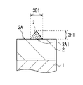
図2は、図1に示した負極の一部を拡大して表している。図1および図2に示した負極では、負極活物質層2の表面が一様に平坦になっている。このような平坦な表面を有する負極活物質層2は、例えば、液相法や塗布法により形成することができる。負極活物質層2の表面が平坦になっている場合には、突起3の幅3D1は、図2に示したように、負極活物質層2の表面2Aと突起3との界面3A1の径である。この幅3D1は、界面3A1が円形状であれば、界面3A1の直径のことであり、界面3A1が楕円状や不定形であれば、界面3A1の最大径のことである。なお、負極活物質層2と突起3とが一体化している場合には、幅3D1は、表面2Aと突起3の輪郭との境目にあるくびれ部分の最大径である。一方、突起3の高さ3H1は、突起3の頂点と界面3A1を含む平面との距離である。なお界面3A1が曲面となる場合には、高さ3H1は、突起3の頂点と幅3D1の両端を通る直線との距離である。
FIG. 2 shows an enlarged part of the negative electrode shown in FIG. In the negative electrode shown in FIGS. 1 and 2, the surface of the negative electrode
次に、負極活物質層2が複数の負極活物質粒子を有する場合について説明する。図3は、負極活物質層2が複数の負極活物質粒子を有する場合における負極の断面構成を模式的に表しており、図4は図3に示した負極の一部を拡大して表している。また、図5は負極の断面構造を拡大して表しており、(A)は走査型電子顕微鏡(scanning electron microscope:SEM)写真(二次電子像)、(B)は(A)に示したSEM像の模式絵である。なお、図5では、複数の負極活物質粒子が粒子内に多層構造をもたない単層構造の場合を示している。図6は負極の平面構造を拡大して表しており、(A)はSEM写真、(B)は(A)に示したSEM像の模式絵である。
Next, the case where the negative electrode
図3〜図6に示したような複数の負極活物質粒子200を有する負極活物質層2は、例えば、上記したように気相法により形成することができる。複数の負極活物質粒子200を有する負極では、突起3の幅は、負極活物質粒子200の粒子径よりも小さく(狭く)なっている。突起3の幅が負極活物質粒子200の粒子径よりも大きい(広い)と、突起3が複数の負極活物質粒子200に渡って配置されることとなる。よって、負極活物質粒子200がリチウムの吸蔵および放出に伴い膨張および収縮した際に、突起3が割れるおそれがある。突起3が割れた結果、突起3の幅は、負極活物質粒子200の粒子径よりも小さく、かつ突起3は、複数の負極活物質粒子200に渡らずに一つの負極活物質粒子200の上面に配置することとなる。すなわち、突起3の幅は、負極活物質粒子200の平均粒子径や負極活物質層2の面内方向における負極活物質粒子200の粒子径よりも小さくなっている。また、突起3が割れた場合には、突起3の一部あるいは全部が剥離するおそれがある。このため、図3〜図6に示したように、あらかじめ突起3の幅は、負極活物質粒子200の粒子径(負極活物質層2の面内方向における粒子径)よりも小さくなっているのが好ましく、突起3は、負極活物質粒子200の頂点近傍に配置されているのが好ましい。
The negative electrode
負極活物質層2が複数の負極活物質粒子を有する場合には、突起3の幅3D2は、図4に示したように、負極活物質層2の表面である負極活物質粒子200の表面200Aと突起3との界面3A2の最大径であり、すなわち幅3D1と同様である。なお、負極活物質粒子200と突起3とが一体化している場合には、幅3D2は、表面200Aと突起3の輪郭との境目にあるくびれ部分の最大径である。一方、突起3の高さ3H2は、突起3の頂点と幅3D2の両端を通る線との距離である。
When the negative electrode
なお、上記した突起3の幅3D1,3D2および高さ3H1,3H2は、SEMにより負極を観察することによって測定できる。また、負極活物質層2の厚さは、負極の断面をSEMにより観察し、負極集電体1の表面から負極活物質層2の表面(負極活物質粒子200の頂点)までの距離を測定することにより特定できる。
Note that the widths 3D1 and 3D2 and the heights 3H1 and 3H2 of the
この負極では、上記したように突起3が負極活物質層2の表面に複数存在していれば、負極活物質層2の構成に依存せず、突起3の数や寸法(幅および高さ)などは任意である。突起3の数としては、負極活物質層2の表面において突起3の面密度が0.02個/μm2以上2.3個/μm2 以下であるのが好ましい。その範囲内であれば、スパイク作用が十分に発揮されるからである。中でも、この面密度は、0.02個/μm2以上0.5個/μm2 以下であるのが好ましい。よりサイクル特性の向上に寄与するからである。
In this negative electrode, if a plurality of
突起3の幅(3D1,3D2)は、その高さ(3H1,3H2)や数によって異なるが、0.06μm以上4μm以下(平均値)であるのが好ましい。この範囲内であると高い効果が得られるからである。詳細には、幅が0.06μmよりも小さい場合には、突起3の高さが高くても負極活物質層2に生じる応力に耐えきれず、その応力に耐えられるように設定すると、その高さは制限されるため、結果として十分なスパイク作用が得られにくくなるものと考えられる。一方、幅が4μmより広い場合には、スパイク作用が生じるようにその高さを設定するとセパレータを突き破るおそれが生じ、セパレータを突き破らない程度にその高さを設定すると突起3の頂点(先端部)が物理的な抵抗(摩擦)を生じさせる程度に鋭角にはなりにくくなるものと考えられる。中でも、突起3の幅は、0.1μm以上2.5μm以下(平均値)であるのが好ましい。より高い効果が得られるからである。
The width (3D1, 3D2) of the
突起3の高さ(3H1,3H2)は、上記した幅(3D1,3D2)および数や、セパレータを備えた二次電池などの電気化学デバイスに用いた場合には、そのセパレータの厚さによっても異なるが、セパレータを突き破ったりしない程度であればよい。中でも、その高さ(平均値)は、0.04μm以上8.5μm以下であるのが好ましい。詳細には、高さが0.04μmより低いと、スパイク作用が得られにくくなるおそれがあり、8.5μmより高いとセパレータの厚さにもよるが、それを突き破りやすくなる。中でも、高さ(平均値)は、0.08μm以上3.2μm以下であるのが好ましい。より高い効果が得られるからである。この場合における突起3の最大高さは、12.7μm以下であるのが好ましく、10.1μm以下であるのが好ましい。高い効果が得られるからである。
The height (3H1, 3H2) of the
また、負極活物質層2が複数の負極活物質粒子を有する場合には、負極活物質粒子の面密度(N2;個/μm2 )に対する突起の面密度(N1;個/μm2 )の比(N1/N2)は、0.05以上11.5以下であるのが好ましい。高い効果が得られるからである。
Further, when the negative electrode
突起3を形成する方法としては、例えば、ディップコーティング法などの液相法や、蒸着法、スパッタ法あるいはCVD(Chemical Vapor Deposition:化学気相成長)法などの気相法が挙げられる。これらの方法を単独で用いてもよいし、2種以上の方法を用いてもよい。中でも、気相法により形成するのが好ましい。突起3の形状が均質となりやすいからである。気相法により突起3を形成する方法としては、例えば、蒸着源あるいはターゲットから所定の大きさの粒子を付着させる方法や、回転蒸着法が挙げられる。回転蒸着法により突起3を形成するには、具体的には、以下の方法による。まず、例えば、負極活物質層2が設けられた負極集電体1をドーム状の支持部材の内側に設置する。この支持部材は、所定の突起形成用材料を含む蒸着源の上に所定の距離をとって覆うように設けられている。この際、負極活物質層2が設けられた負極集電体1を負極活物質層2の表面が蒸着源に対して垂直方向から所定の角度となるように支持部材に設置する。続いて、支持部材を回転させながら、電子ビームを蒸着源に照射することにより、負極活物質層2の表面に、その材料を堆積させる。この際、支持部材は、蒸着源に対して垂直方向を軸にして回転する。これにより突起3が形成される。この回転蒸着法により形成された突起3は、蒸着物が螺旋状に堆積され、その結果、円錐形となりやすい。
Examples of the method for forming the
この負極は、例えば、以下の手順によって製造される。 This negative electrode is manufactured, for example, by the following procedure.
まず、負極集電体1の両面に、負極活物質層2を形成する。この負極活物質層2を形成する場合には、例えば、蒸着法などの気相法によって負極集電体1の表面に負極材料を堆積させて、複数の負極活物質粒子を形成する。最後に、負極活物質層2の表面に突起3を形成する。この突起3を形成する場合には、例えば、蒸着法などの気相法によって負極活物質層2の表面に負極材料を堆積させて形成する。これにより、負極が完成する。
First, the negative electrode
この負極によれば、負極活物質層2の表面に複数の突起を有するので、その突起3を設けない場合と比較して、電極反応物質を吸蔵および放出しても、負極活物質層2の膨張および収縮が抑制され、負極集電体1の変形や負極活物質層2の剥離などが生じにくくなり、負極の構造上の安定性が向上する。したがって、負極がセパレータを備えた二次電池などの電気化学デバイスに用いられた場合に、充放電を繰り返しても負極の構造が安定して保持され、サイクル特性の向上に寄与することができる。
According to this negative electrode, since the negative electrode
特に、突起3の面密度、幅あるいは高さを上記の適した範囲とすれば、サイクル特性をより向上させることができる。なお、この突起3の適した面密度等の範囲は、負極活物質層2が複数の負極活物質粒子を有する場合においても同様である。
In particular, if the surface density, width, or height of the
また、負極活物質層2が複数の負極活物質粒子を有する場合に、突起の面密度(N1)に対する前記負極活物質粒子の面密度(N2)の比(N1/N2)を0.01以上11.5以下とすることにより、より高い効果を得ることができる。
Further, when the negative electrode
負極活物質層2が負極活物質としてケイ素の単体、合金および化合物のうちの少なくとも1種を含む場合には、電極反応物質の吸蔵および放出に伴う、負極活物質層2の膨張および収縮による応力が大きいため、その応力が比較的小さい負極活物質を含む負極よりも、サイクル特性の向上により寄与することができる。
When the negative electrode
ちなみに、「背景技術」に記載した特許文献4(特開2006−278270号公報)、特許文献5(特開2008−004281号公報)では、蒸着法により形成した負極活物質層の表面に、蒸着源から飛び散った負極活物質が付着する、いわゆるスプラッシュにより、負極活物質層の表面に突起が形成されることが示されている。しかしながら、このスプラッシュが生じると、負極活物質層および負極集電体が飛び散った負極活物質により溶けてしまうので、負極として機能しないものになる。このため、蒸着法により負極活物質層を形成する際には、通常、スプラッシュが生じない条件で行うこととなる。また、負極として機能する程度に、突起が形成されたとしても、特許文献4,5では、突起の幅が大きく、しかも頂点が潰れていたり、削れていたりすることから、本発明の負極と同様の作用(スパイク作用)は得られないものと考えられる。 Incidentally, in Patent Document 4 (Japanese Patent Laid-Open No. 2006-278270) and Patent Document 5 (Japanese Patent Laid-Open No. 2008-004281) described in “Background Art”, vapor deposition is performed on the surface of the negative electrode active material layer formed by the vapor deposition method. It is shown that protrusions are formed on the surface of the negative electrode active material layer by so-called splash, in which the negative electrode active material scattered from the source adheres. However, when this splash occurs, the negative electrode active material layer and the negative electrode current collector are dissolved by the scattered negative electrode active material, and thus do not function as a negative electrode. For this reason, when forming a negative electrode active material layer by a vapor deposition method, it will carry out normally on the conditions which a splash does not produce. Further, even if the protrusion is formed to such an extent that it functions as a negative electrode, in Patent Documents 4 and 5, since the width of the protrusion is large and the apex is crushed or scraped, it is the same as the negative electrode of the present invention. It is considered that the action (spike action) cannot be obtained.
次に、上記した負極の使用例について説明する。ここで、電気化学デバイスの一例として二次電池を例に挙げると、負極は以下のように用いられる。 Next, usage examples of the above-described negative electrode will be described. Here, taking a secondary battery as an example of an electrochemical device, the negative electrode is used as follows.
(第1の二次電池)
図7および図8は第1の二次電池の断面構成を表しており、図8では図7に示した巻回電極体20の一部を拡大して示している。ここで説明する二次電池は、例えば、負極22の容量がリチウムの吸蔵および放出に基づいて表されるリチウムイオン二次電池である。
(First secondary battery)
7 and 8 show a cross-sectional configuration of the first secondary battery. FIG. 8 shows an enlarged part of the spirally wound electrode body 20 shown in FIG. The secondary battery described here is, for example, a lithium ion secondary battery in which the capacity of the negative electrode 22 is expressed based on insertion and extraction of lithium.
この二次電池は、主に、ほぼ中空円柱状の電池缶11の内部に、セパレータ23を介して正極21と負極22とが巻回された巻回電極体20と、一対の絶縁板12,13とが収納されたものである。この電池缶11を含む電池構造は、円筒型と呼ばれている。
The secondary battery mainly includes a wound electrode body 20 in which a
電池缶11は、例えば、鉄、アルミニウムあるいはそれらの合金などの金属材料によって構成されており、その一端部は閉鎖されていると共に他端部は開放されている。一対の絶縁板12,13は、巻回電極体20を挟み、その巻回周面に対して垂直に延在するように配置されている。 The battery can 11 is made of, for example, a metal material such as iron, aluminum, or an alloy thereof, and one end thereof is closed and the other end is opened. The pair of insulating plates 12 and 13 are arranged so as to extend perpendicular to the winding peripheral surface with the winding electrode body 20 interposed therebetween.
電池缶11の開放端部には、電池蓋14と、その内側に設けられた安全弁機構15および熱感抵抗素子(Positive Temperature Coefficient:PTC素子)16とがガスケット17を介してかしめられて取り付けられている。これにより、電池缶11の内部は密閉されている。電池蓋14は、例えば、電池缶11と同様の材料によって構成されている。安全弁機構15は、熱感抵抗素子16を介して電池蓋14と電気的に接続されている。この安全弁機構15では、内部短絡、あるいは外部からの加熱などに起因して内圧が一定以上となった場合に、ディスク板15Aが反転して電池蓋14と巻回電極体20との間の電気的接続が切断されるようになっている。熱感抵抗素子16は、温度の上昇に応じた抵抗の増大によって電流を制限し、大電流に起因する異常な発熱を防止するものである。ガスケット17は、例えば、絶縁材料によって構成されており、その表面にはアスファルトが塗布されている。
A battery lid 14 and a
巻回電極体20の中心には、センターピン24が挿入されていてもよい。この巻回電極体20では、アルミニウムなどの金属材料によって構成された正極リード25が正極21に接続されていると共に、ニッケルなどの金属材料によって構成された負極リード26が負極22に接続されている。正極リード25は、安全弁機構15に溶接されて電池蓋14と電気的に接続されており、負極リード26は、電池缶11に溶接されて電気的に接続されている。
A center pin 24 may be inserted in the center of the wound electrode body 20. In this wound electrode body 20, a
正極21は、例えば、一対の面を有する正極集電体21Aの両面に正極活物質層21Bが設けられたものである。この正極集電体21Aは、例えば、アルミニウム、ニッケル、あるいはステンレスなどの金属材料によって構成されている。なお、正極活物質層21Bは、正極活物質を含んでおり、必要に応じて上記した結着剤や導電剤などの他の材料を含んでいてもよい。
For example, the
正極活物質は、電極反応物質であるリチウムを吸蔵および放出することが可能な正極材料のいずれか1種あるいは2種以上を含んでいる。この正極材料としては、例えば、リチウム含有化合物が好ましい。高いエネルギー密度が得られるからである。このリチウム含有化合物としては、例えば、リチウムと遷移金属元素とを含む複合酸化物、あるいはリチウムと遷移金属元素とを含むリン酸化合物が挙げられ、特に、遷移金属元素としてコバルト、ニッケル、マンガンおよび鉄からなる群のうちの少なくとも1種を含むものが好ましい。より高い電圧が得られるからである。その化学式は、例えば、Lix M1O2 あるいはLiy M2PO4 で表される。式中、M1およびM2は、1種類以上の遷移金属元素を表す。xおよびyの値は、二次電池の充放電状態によって異なり、通常、0.05≦x≦1.10、0.05≦y≦1.10である。 The positive electrode active material includes one or more positive electrode materials capable of inserting and extracting lithium as an electrode reactant. As the positive electrode material, for example, a lithium-containing compound is preferable. This is because a high energy density can be obtained. Examples of the lithium-containing compound include a composite oxide containing lithium and a transition metal element, or a phosphate compound containing lithium and a transition metal element. In particular, cobalt, nickel, manganese, and iron are used as the transition metal element. Those containing at least one of the group consisting of: This is because a higher voltage can be obtained. The chemical formula is represented by, for example, Li x M1O 2 or Li y M2PO 4 . In the formula, M1 and M2 represent one or more transition metal elements. The values of x and y vary depending on the charge / discharge state of the secondary battery, and are generally 0.05 ≦ x ≦ 1.10 and 0.05 ≦ y ≦ 1.10.
リチウムと遷移金属元素とを含む複合酸化物としては、例えば、リチウムコバルト複合酸化物(Lix CoO2 )、リチウムニッケル複合酸化物(Lix NiO2 )、リチウムニッケルコバルト複合酸化物(Lix Ni(1-z) Coz O2 (z<1))、リチウムニッケルコバルトマンガン複合酸化物(Lix Ni(1-v-w) Cov Mnw O2 (v+w<1))、あるいはスピネル型構造を有するリチウムマンガン複合酸化物(LiMn2 O4 )などが挙げられる。中でも、コバルトを含む複合酸化物が好ましい。高い容量が得られると共に優れたサイクル特性も得られるからである。また、リチウムと遷移金属元素とを含むリン酸化合物としては、例えば、リチウム鉄リン酸化合物(LiFePO4 )あるいはリチウム鉄マンガンリン酸化合物(LiFe(1-u) Mnu PO4 (u<1))などが挙げられる。 Examples of the composite oxide containing lithium and a transition metal element include lithium cobalt composite oxide (Li x CoO 2 ), lithium nickel composite oxide (Li x NiO 2 ), and lithium nickel cobalt composite oxide (Li x Ni). (1-z) Co z O 2 (z <1)), lithium nickel cobalt manganese composite oxide (Li x Ni (1-vw) Co v Mn w O 2 (v + w <1)), or spinel type structure And a lithium manganese composite oxide (LiMn 2 O 4 ). Among these, a complex oxide containing cobalt is preferable. This is because high capacity can be obtained and excellent cycle characteristics can be obtained. Examples of the phosphate compound containing lithium and a transition metal element include a lithium iron phosphate compound (LiFePO 4 ) or a lithium iron manganese phosphate compound (LiFe (1-u) Mn u PO 4 (u <1). ) And the like.
この他、正極材料としては、例えば、酸化チタン、酸化バナジウムあるいは二酸化マンガンなどの酸化物や、二硫化チタンあるいは硫化モリブデンなどの二硫化物や、セレン化ニオブなどのカルコゲン化物や、硫黄、ポリアニリンあるいはポリチオフェンなどの導電性高分子も挙げられる。 In addition, examples of the positive electrode material include oxides such as titanium oxide, vanadium oxide and manganese dioxide, disulfides such as titanium disulfide and molybdenum sulfide, chalcogenides such as niobium selenide, sulfur, polyaniline or Examples also include conductive polymers such as polythiophene.
負極22は、上記した負極と同様の構成を有しており、例えば、一対の面を有する負極集電体22Aの両面に負極活物質層22Bおよび突起22Cが設けられたものである。負極集電体22A、負極活物質層22Bおよび突起22Cの構成は、それぞれ上記した負極における負極集電体1、負極活物質層2および突起3の構成と同様である。この負極22では、リチウムを吸蔵および放出することが可能な負極材料の充電容量が正極21の充電容量よりも大きくなっているのが好ましい。満充電時においても、負極22にリチウムがデンドライトとなって析出する可能性が低くなるからである。
The negative electrode 22 has the same configuration as the negative electrode described above. For example, the negative electrode active material layer 22B and the
セパレータ23は、正極21と負極22とを隔離し、両極の接触に起因する電流の短絡(ショート)を防止しながらリチウムイオンを通過させるものである。このセパレータ23は、例えば、ポリテトラフルオロエチレン、ポリプロピレンあるいはポリエチレンなどの合成樹脂からなる多孔質膜や、セラミックからなる多孔質膜などによって構成されており、これらの2種以上の多孔質膜が積層されたものであってもよい。中でも、ポリオレフィン製の多孔質膜は、ショート防止効果に優れ、かつシャットダウン効果による二次電池の安全性向上を図ることができるので好ましい。特に、ポリエチレンは、100℃以上160℃以下でシャットダウン効果を得ることができると共に、電気化学的安定性が優れているので好ましい。また、ポリプロピレンも好ましく、他にも化学的安定性を備えた樹脂であれば、ポリエチレンあるいはポリプロピレンと共重合させたものや、ブレンド化したものであってもよい。
The
このセパレータ23には、液状の電解質である電解液が含浸されている。この電解液は、溶媒と、それに溶解された電解質塩とを含んでいる。
The
溶媒は、例えば、有機溶剤などの非水溶媒のいずれか1種あるいは2種以上を含有している。この非水溶媒としては、例えば、炭酸エチレン、炭酸プロピレン、炭酸ブチレン、炭酸ジメチル、炭酸ジエチル、炭酸エチルメチル、炭酸メチルプロピル、γ−ブチロラクトン、γ−バレロラクトン、1,2−ジメトキシエタン、テトラヒドロフラン、2−メチルテトラヒドロフラン、テトラヒドロピラン、1,3−ジオキソラン、4−メチル−1,3−ジオキソラン、1,3−ジオキサン、1,4−ジオキサン、酢酸メチル、酢酸エチル、プロピオン酸メチル、プロピオン酸エチル、酪酸メチル、イソ酪酸メチル、トリメチル酢酸メチル、トリメチル酢酸エチル、アセトニトリル、グルタロニトリル、アジポニトリル、メトキシアセトニトリル、3−メトキシプロピオニトリル、N,N−ジメチルホルムアミド、N−メチルピロリジノン、N−メチルオキサゾリジノン、N,N’−ジメチルイミダゾリジノン、ニトロメタン、ニトロエタン、スルホラン、燐酸トリメチルあるいはジメチルスルホキシドなどが挙げられる。中でも、炭酸エチレン、炭酸プロピレン、炭酸ジメチル、炭酸ジエチルおよび炭酸エチルメチルからなる群のうちの少なくとも1種が好ましい。優れた電池容量、サイクル特性および保存特性が得られるからである。この場合には、特に、炭酸エチレンあるいは炭酸プロピレンなどの高粘度(高誘電率)溶媒(例えば、比誘電率ε≧30)と炭酸ジメチル、炭酸エチルメチルあるいは炭酸ジエチルなどの低粘度溶媒(例えば、粘度≦1mPa・s)との組み合わせがより好ましい。電解質塩の解離性およびイオンの移動度が向上するため、より高い効果が得られるからである。 The solvent contains, for example, one or more of nonaqueous solvents such as organic solvents. Examples of the non-aqueous solvent include ethylene carbonate, propylene carbonate, butylene carbonate, dimethyl carbonate, diethyl carbonate, ethyl methyl carbonate, methyl propyl carbonate, γ-butyrolactone, γ-valerolactone, 1,2-dimethoxyethane, tetrahydrofuran, 2-methyltetrahydrofuran, tetrahydropyran, 1,3-dioxolane, 4-methyl-1,3-dioxolane, 1,3-dioxane, 1,4-dioxane, methyl acetate, ethyl acetate, methyl propionate, ethyl propionate, Methyl butyrate, methyl isobutyrate, methyl trimethylacetate, ethyl trimethylacetate, acetonitrile, glutaronitrile, adiponitrile, methoxyacetonitrile, 3-methoxypropionitrile, N, N-dimethylformamide, N-methylpyrrolidinone, N -Methyloxazolidinone, N, N'-dimethylimidazolidinone, nitromethane, nitroethane, sulfolane, trimethyl phosphate or dimethyl sulfoxide. Among these, at least one selected from the group consisting of ethylene carbonate, propylene carbonate, dimethyl carbonate, diethyl carbonate, and ethyl methyl carbonate is preferable. This is because excellent battery capacity, cycle characteristics and storage characteristics can be obtained. In this case, in particular, a high viscosity (high dielectric constant) solvent such as ethylene carbonate or propylene carbonate (for example, relative dielectric constant ε ≧ 30) and a low viscosity solvent such as dimethyl carbonate, ethyl methyl carbonate or diethyl carbonate (for example, A combination with (viscosity ≦ 1 mPa · s) is more preferable. This is because the dissociation property of the electrolyte salt and the ion mobility are improved, and thus higher effects can be obtained.
この溶媒は、化1〜化3で表される不飽和結合を有する環状炭酸エステルを含有しているのが好ましい。高いサイクル特性が得られるからである。これらは単独でも良いし、複数種が混合されてもよい。
This solvent preferably contains a cyclic carbonate having an unsaturated bond represented by

化1に示した不飽和結合を有する環状炭酸エステルは、炭酸ビニレン系化合物である。この炭酸ビニレン系化合物としては、例えば、炭酸ビニレン(1,3−ジオキソール−2−オン)、炭酸メチルビニレン(4−メチル−1,3−ジオキソール−2−オン)、炭酸エチルビニレン(4−エチル−1,3−ジオキソール−2−オン)、4,5−ジメチル−1,3−ジオキソール−2−オン、4,5−ジエチル−1,3−ジオキソール−2−オン、4−フルオロ−1,3−ジオキソール−2−オン、あるいは4−トリフルオロメチル−1,3−ジオキソール−2−オンなどが挙げられ、中でも炭酸ビニレンが好ましい。容易に入手可能であると共に、高い効果が得られるからである。
The cyclic ester carbonate having an unsaturated bond shown in
化2に示した不飽和結合を有する環状炭酸エステルは、炭酸ビニルエチレン系化合物である。炭酸ビニルエチレン系化合物としては、例えば、炭酸ビニルエチレン(4−ビニル−1,3−ジオキソラン−2−オン)、4−メチル−4−ビニル−1,3−ジオキソラン−2−オン、4−エチル−4−ビニル−1,3−ジオキソラン−2−オン、4−n−プロピル−4−ビニル−1,3−ジオキソラン−2−オン、5−メチル−4−ビニル−1,3−ジオキソラン−2−オン、4,4−ジビニル−1,3−ジオキソラン−2−オン、あるいは4,5−ジビニル−1,3−ジオキソラン−2−オンなどが挙げられ、中でも炭酸ビニルエチレンが好ましい。容易に入手可能であると共に、高い効果が得られるからである。もちろん、R13〜R16としては、全てがビニル基でもよいし、全てがアリル基でもよいし、ビニル基とアリル基とが混在していてもよい。
The cyclic ester carbonate having an unsaturated bond shown in
化3に示した不飽和結合を有する環状炭酸エステルは、炭酸メチレンエチレン系化合物である。炭酸メチレンエチレン系化合物としては、4−メチレン−1,3−ジオキソラン−2−オン、4,4−ジメチル−5−メチレン−1,3−ジオキソラン−2−オン、あるいは4,4−ジエチル−5−メチレン−1,3−ジオキソラン−2−オンなどが挙げられる。この炭酸メチレンエチレン系化合物としては、1つのメチレン基を有するもの(化3に示した化合物)の他、2つのメチレン基を有するものであってもよい。
The cyclic ester carbonate having an unsaturated bond shown in
なお、不飽和結合を有する環状炭酸エステルとしては、化1〜化3に示したものの他、ベンゼン環を有する炭酸カテコール(カテコールカーボネート)などであってもよい。
The cyclic carbonate having an unsaturated bond may be catechol carbonate having a benzene ring in addition to those shown in
溶媒中における上記した不飽和結合を有する環状炭酸エステルの含有量は、0.01重量%以上10重量%以下であるのが好ましい。十分な効果が得られるからである。 The content of the cyclic carbonate having an unsaturated bond in the solvent is preferably 0.01% by weight or more and 10% by weight or less. This is because a sufficient effect can be obtained.
また、溶媒は、化4で表されるハロゲンを構成元素として有する鎖状炭酸エステルおよび化5で表されるハロゲンを構成元素として有する環状炭酸エステルのうちの少なくとも1種を含有しているのが好ましい。負極22の表面に安定な保護膜が形成されて電解液の分解反応が抑制されるため、サイクル特性が向上するからである。 The solvent contains at least one of a chain carbonate having a halogen represented by Chemical Formula 4 as a constituent element and a cyclic carbonate having a halogen represented by Chemical Formula 5 as a constituent element. preferable. This is because a stable protective film is formed on the surface of the negative electrode 22 and the decomposition reaction of the electrolytic solution is suppressed, so that the cycle characteristics are improved.
なお、化4中のR21〜R26は、同一でもよいし、異なってもよい。このことは、化5中のR27〜R30についても同様である。ハロゲンの種類は、特に限定されないが、例えば、フッ素、塩素および臭素からなる群のうちの少なくとも1種が挙げられ、中でも、フッ素が好ましい。高い効果が得られるからである。もちろん、他のハロゲンであってもよい。 In addition, R21 to R26 in Chemical formula 4 may be the same or different. The same applies to R27 to R30 in Chemical Formula 5. Although the kind of halogen is not specifically limited, For example, at least 1 type in the group which consists of a fluorine, chlorine, and a bromine is mentioned, Among these, a fluorine is preferable. This is because a high effect can be obtained. Of course, other halogens may be used.
ハロゲンの数は、1つよりも2つが好ましく、さらに3つ以上であってもよい。保護膜を形成する能力が高くなり、より強固で安定な保護膜が形成されるため、電解液の分解反応がより抑制されるからである。 The number of halogens is preferably two rather than one, and may be three or more. This is because the ability to form a protective film is increased and a stronger and more stable protective film is formed, so that the decomposition reaction of the electrolytic solution is further suppressed.
化4に示したハロゲンを有する鎖状炭酸エステルとしては、例えば、炭酸フルオロメチルメチル、炭酸ビス(フルオロメチル)あるいは炭酸ジフルオロメチルメチルなどが挙げられる。これらは単独でもよいし、複数種が混合されてもよい。 Examples of the chain carbonate having a halogen shown in Chemical Formula 4 include fluoromethyl methyl carbonate, bis (fluoromethyl) carbonate, difluoromethyl methyl carbonate, and the like. These may be single and multiple types may be mixed.
化5に示したハロゲンを有する環状炭酸エステルとしては、例えば、化6および化7で表される一連の化合物が挙げられる。すなわち、化6に示した(1)の4−フルオロ−1,3−ジオキソラン−2−オン、(2)の4−クロロ−1,3−ジオキソラン−2−オン、(3)の4,5−ジフルオロ−1,3−ジオキソラン−2−オン、(4)のテトラフルオロ−1,3−ジオキソラン−2−オン、(5)の4−フルオロ−5−クロロ−1,3−ジオキソラン−2−オン、(6)の4,5−ジクロロ−1,3−ジオキソラン−2−オン、(7)のテトラクロロ−1,3−ジオキソラン−2−オン、(8)の4,5−ビストリフルオロメチル−1,3−ジオキソラン−2−オン、(9)の4−トリフルオロメチル−1,3−ジオキソラン−2−オン、(10)の4,5−ジフルオロ−4,5−ジメチル−1,3−ジオキソラン−2−オン、(11)の4−メチル−5,5−ジフルオロ−1,3−ジオキソラン−2−オン、(12)の4−エチル−5,5−ジフルオロ−1,3−ジオキソラン−2−オンなどである。また、化7に示した(1)の4−トリフルオロメチル−5−フルオロ−1,3−ジオキソラン−2−オン、(2)の4−トリフルオロメチル−5−メチル−1,3−ジオキソラン−2−オン、(3)の4−フルオロ−4,5−ジメチル−1,3−ジオキソラン−2−オン、(4)の4,4−ジフルオロ−5−(1,1−ジフルオロエチル)−1,3−ジオキソラン−2−オン、(5)の4,5−ジクロロ−4,5−ジメチル−1,3−ジオキソラン−2−オン、(6)の4−エチル−5−フルオロ−1,3−ジオキソラン−2−オン、(7)の4−エチル−4,5−ジフルオロ−1,3−ジオキソラン−2−オン、(8)の4−エチル−4,5,5−トリフルオロ−1,3−ジオキソラン−2−オン、(9)の4−フルオロ−4−メチル−1,3−ジオキソラン−2−オンなどである。これらは単独でもよいし、複数種が混合されてもよい。
Examples of the cyclic carbonate having a halogen shown in Chemical formula 5 include a series of compounds represented by Chemical formula 6 and Chemical formula 7. That is, 4-fluoro-1,3-dioxolan-2-one of (1) shown in Chemical formula 6, 4-chloro-1,3-dioxolan-2-one of (2), 4,5 of (3) -Difluoro-1,3-dioxolan-2-one, (4) tetrafluoro-1,3-dioxolan-2-one, (5) 4-fluoro-5-chloro-1,3-dioxolane-2-one ON, (6) 4,5-dichloro-1,3-dioxolan-2-one, (7) tetrachloro-1,3-dioxolan-2-one, (8) 4,5-
中でも、4−フルオロ−1,3−ジオキソラン−2−オンあるいは4,5−ジフルオロ−1,3−ジオキソラン−2−オンが好ましく、4,5−ジフルオロ−1,3−ジオキソラン−2−オンがより好ましい。特に、4,5−ジフルオロ−1,3−ジオキソラン−2−オンとしては、シス異性体よりもトランス異性体が好ましい。容易に入手可能であると共に、高い効果が得られるからである。 Of these, 4-fluoro-1,3-dioxolan-2-one or 4,5-difluoro-1,3-dioxolan-2-one is preferred, and 4,5-difluoro-1,3-dioxolan-2-one is preferred. More preferred. In particular, 4,5-difluoro-1,3-dioxolan-2-one is preferably a trans isomer rather than a cis isomer. This is because it is easily available and a high effect can be obtained.
溶媒は、スルトン(環状スルホン酸エステル)を含有していてもよい。このスルトンは、例えば、プロパンスルトンあるいはプロペンスルトンなどである。これらは単独でもよいし、複数種が混合されてもよい。 The solvent may contain sultone (cyclic sulfonate ester). This sultone is, for example, propane sultone or propene sultone. These may be single and multiple types may be mixed.
また、溶媒は、酸無水物を含有しているのが好ましい。高いサイクル特性が得られるからである。この酸無水物は、例えば、コハク酸無水物、グルタル酸無水物あるいはマレイン酸無水物などのカルボン酸無水物や、エタンジスルホン酸無水物あるいはプロパンジスルホン酸無水物などのジスルホン酸無水物や、スルホ安息香酸無水物、スルホプロピオン酸無水物あるいはスルホ酪酸無水物などのカルボン酸とスルホン酸との無水物などであり、中でも、スルホ安息香酸無水物が好ましい。これらは単独でもよいし、複数種が混合されてもよい。 Moreover, it is preferable that the solvent contains an acid anhydride. This is because high cycle characteristics can be obtained. Examples of the acid anhydride include carboxylic acid anhydrides such as succinic acid anhydride, glutaric acid anhydride and maleic acid anhydride, disulfonic acid anhydrides such as ethanedisulfonic acid anhydride and propanedisulfonic acid anhydride, Examples thereof include anhydrides of carboxylic acid and sulfonic acid such as benzoic acid anhydride, sulfopropionic acid anhydride or sulfobutyric acid anhydride, among which sulfobenzoic acid anhydride is preferable. These may be single and multiple types may be mixed.
電解質塩は、例えば、リチウム塩などの軽金属塩のいずれか1種あるいは2種以上を含んでいる。このリチウム塩としては、例えば、六フッ化リン酸リチウム、四フッ化ホウ酸リチウム、過塩素酸リチウムあるいは六フッ化ヒ酸リチウムなどが挙げられる。優れた電池容量、サイクル特性および保存特性が得られるからである。中でも、六フッ化リン酸リチウムが好ましい。内部抵抗が低下するため、より高い効果が得られるからである。 The electrolyte salt includes, for example, any one or more of light metal salts such as a lithium salt. Examples of the lithium salt include lithium hexafluorophosphate, lithium tetrafluoroborate, lithium perchlorate, and lithium hexafluoroarsenate. This is because excellent battery capacity, cycle characteristics and storage characteristics can be obtained. Among these, lithium hexafluorophosphate is preferable. This is because a higher effect can be obtained because the internal resistance is lowered.
この電解質塩は、化8〜化10で表される化合物からなる群のうちの少なくとも1種を含有しているのが好ましい。上記した六フッ化リン酸リチウム等と一緒に用いられた場合に、より高い効果が得られるからである。なお、化8中のR33は、同一でもよいし、異なってもよい。このことは、化9中のR41〜R43および化10中のR51およびR52についても同様である。 This electrolyte salt preferably contains at least one selected from the group consisting of compounds represented by Chemical Formulas 8 to 10. This is because a higher effect can be obtained when used together with the above-described lithium hexafluorophosphate or the like. In addition, R33 in Chemical formula 8 may be the same or different. The same applies to R41 to R43 in Chemical Formula 9 and R51 and R52 in Chemical Formula 10.
なお、長周期型周期表における1族元素とは、水素、リチウム、ナトリウム、カリウム、ルビジウム、セシウムおよびフランシウムである。2族元素とは、ベリリウム、マグネシウム、カルシウム、ストロンチウム、バリウムおよびラジウムである。13族元素とは、ホウ素、アルミニウム、ガリウム、インジウムおよびタリウムである。14族元素とは、炭素、ケイ素、ゲルマニウム、スズおよび鉛である。15族元素とは、窒素、リン、ヒ素、アンチモンおよびビスマスである。
The
化8に示した化合物としては、例えば、化11の(1)〜(6)で表される化合物などが挙げられる。化9に示した化合物としては、例えば、化12の(1)〜(8)で表される化合物などが挙げられる。化10に示した化合物としては、例えば、化13で表される化合物などが挙げられる。なお、化8〜化10に示した構造を有する化合物であれば、化11〜化13に示した化合物に限定されないことは言うまでもない。 Examples of the compound represented by Chemical formula 8 include the compounds represented by Chemical formulas (1) to (6). Examples of the compound represented by Chemical formula 9 include the compounds represented by Chemical formulas (1) to (8). Examples of the compound represented by Chemical formula 10 include the compound represented by Chemical formula 13 and the like. It is needless to say that the compound having the structure shown in Chemical Formula 8 to Chemical Formula 10 is not limited to the compound shown in Chemical Formula 11 to Chemical Formula 13.
また、電解質塩は、化14〜化16で表される化合物からなる群のうちの少なくとも1種を含有しているのが好ましい。上記した六フッ化リン酸リチウム等と一緒に用いられた場合に、より高い効果が得られるからである。なお、化14中のmおよびnは、同一でもよいし、異なってもよい。このことは、化16中のp、qおよびrについても同様である。 Moreover, it is preferable that electrolyte salt contains at least 1 sort (s) of the group which consists of a compound represented by Chemical formula 14-Chemical formula 16. This is because a higher effect can be obtained when used together with the above-described lithium hexafluorophosphate or the like. Note that m and n in Chemical formula 14 may be the same or different. The same applies to p, q and r in Chemical formula 16.
化14に示した鎖状の化合物としては、例えば、ビス(トリフルオロメタンスルホニル)イミドリチウム(LiN(CF3 SO2 )2 )、ビス(ペンタフルオロエタンスルホニル)イミドリチウム(LiN(C2 F5 SO2 )2 )、(トリフルオロメタンスルホニル)(ペンタフルオロエタンスルホニル)イミドリチウム(LiN(CF3 SO2 )(C2 F5 SO2 ))、(トリフルオロメタンスルホニル)(ヘプタフルオロプロパンスルホニル)イミドリチウム(LiN(CF3 SO2 )(C3 F7 SO2 ))、あるいは(トリフルオロメタンスルホニル)(ノナフルオロブタンスルホニル)イミドリチウム(LiN(CF3 SO2 )(C4 F9 SO2 ))などが挙げられる。これらは単独でもよいし、複数種が混合されてもよい。 Examples of the chain compound shown in Chemical formula 14 include bis (trifluoromethanesulfonyl) imide lithium (LiN (CF 3 SO 2 ) 2 ), bis (pentafluoroethanesulfonyl) imide lithium (LiN (C 2 F 5 SO 2 ) 2 ), (trifluoromethanesulfonyl) (pentafluoroethanesulfonyl) imide lithium (LiN (CF 3 SO 2 ) (C 2 F 5 SO 2 )), (trifluoromethanesulfonyl) (heptafluoropropanesulfonyl) imide lithium ( LiN (CF 3 SO 2 ) (C 3 F 7 SO 2 )) or (trifluoromethanesulfonyl) (nonafluorobutanesulfonyl) imidolithium (LiN (CF 3 SO 2 ) (C 4 F 9 SO 2 )) Can be mentioned. These may be single and multiple types may be mixed.
化15に示した環状の化合物としては、例えば、化17で表される一連の化合物が挙げられる。すなわち、化17に示した(1)の1,2−パーフルオロエタンジスルホニルイミドリチウム、(2)の1,3−パーフルオロプロパンジスルホニルイミドリチウム、(3)の1,3−パーフルオロブタンジスルホニルイミドリチウム、(4)の1,4−パーフルオロブタンジスルホニルイミドリチウムなどである。これらは単独でもよいし、複数種が混合されてもよい。
Examples of the cyclic compound represented by
化16に示した鎖状の化合物としては、例えば、リチウムトリス(トリフルオロメタンスルホニル)メチド(LiC(CF3 SO2 )3 )などが挙げられる。 Examples of the chain compound shown in Chemical formula 16 include lithium tris (trifluoromethanesulfonyl) methide (LiC (CF 3 SO 2 ) 3 ).
電解質塩の含有量は、溶媒に対して0.3mol/kg以上3.0mol/kg以下であるのが好ましい。この範囲外では、イオン伝導性が極端に低下する可能性があるからである。 The content of the electrolyte salt is preferably 0.3 mol / kg or more and 3.0 mol / kg or less with respect to the solvent. This is because, outside this range, the ion conductivity may be extremely lowered.
この二次電池は、例えば、以下の手順によって製造される。 This secondary battery is manufactured, for example, by the following procedure.
まず、正極21を作製する。最初に、正極活物質と、結着剤と、導電剤とを混合して正極合剤としたのち、有機溶剤に分散させてペースト状の正極合剤スラリーとする。続いて、ドクタブレードあるいはバーコータなどによって正極集電体21Aの両面に正極合剤スラリーを均一に塗布して乾燥させる。最後に、必要に応じて加熱しながらロールプレス機などによって塗膜を圧縮成型して正極活物質層21Bを形成する。この場合には、圧縮成型を複数回に渡って繰り返してもよい。
First, the
また、上記した負極の作製手順と同様の手順により、負極集電体22Aの両面に負極活物質層22Bおよび突起22Cを形成して負極22を作製する。
Further, the negative electrode 22 is manufactured by forming the negative electrode active material layer 22B and the
次に、正極21および負極22を用いて巻回電極体20を作製する。最初に、正極集電体21Aに正極リード25を溶接などして取り付けると共に、負極集電体22Aに負極リード26を溶接などして取り付ける。こののち、セパレータ23を介して正極21と負極22とを積層させたのち、長手方向において巻回させる。
Next, the wound electrode body 20 is produced using the
二次電池の組み立ては、以下のようにして行う。最初に、正極リード25の先端部を安全弁機構15に溶接すると共に、負極リード26の先端部を電池缶11に溶接する。続いて、巻回電極体20を一対の絶縁板12,13で挟みながら電池缶11の内部に収納する。続いて、電池缶11の内部に電解液を注入してセパレータ23に含浸させる。最後に、電池缶11の開口端部に電池蓋14、安全弁機構15および熱感抵抗素子16をガスケット17を介してかしめることにより固定する。これにより、図7および図8に示した二次電池が完成する。
The secondary battery is assembled as follows. First, the tip of the
この二次電池では、充電を行うと、例えば、正極21からリチウムイオンが放出され、セパレータ23に含浸された電解液を介して負極22に吸蔵される。一方、放電を行うと、例えば、負極22からリチウムイオンが放出され、セパレータ23に含浸された電解液を介して正極21に吸蔵される。
In the secondary battery, when charged, for example, lithium ions are extracted from the
この円筒型の二次電池によれば、負極22が上記した負極と同様の構成を有しているので、その負極22の構造上の安定性が向上する。これにより、負極22においてリチウムイオンが吸蔵および放出されても、負極集電体22Aの変形や負極活物質層22Bの剥離が抑制されるため、サイクル特性を向上させることができる。 According to this cylindrical secondary battery, since the negative electrode 22 has the same configuration as the above-described negative electrode, the structural stability of the negative electrode 22 is improved. Thereby, even if lithium ions are occluded and released in the negative electrode 22, deformation of the negative electrode current collector 22 </ b> A and peeling of the negative electrode active material layer 22 </ b> B are suppressed, so that cycle characteristics can be improved.
この場合には、負極22が高容量化に有利なケイ素等(リチウムを吸蔵および放出することが可能であると共に金属元素および半金属元素のうちの少なくとも1種を有する材料)を含む場合に、特にサイクル特性を向上させることができる。 In this case, when the negative electrode 22 contains silicon or the like (material that can occlude and release lithium and has at least one of a metal element and a metalloid element) that is advantageous for increasing the capacity, In particular, the cycle characteristics can be improved.
この二次電池に関する他の効果は、上記した負極と同様である。 Other effects relating to the secondary battery are the same as those of the above-described negative electrode.
(第2の二次電池)
図9は第2の二次電池の分解斜視構成を表しており、図10は図9に示した巻回電極体30のX−X線に沿った断面を拡大して示している。この二次電池は、例えば、上記した第1の二次電池と同様にリチウムイオン二次電池であり、主に、フィルム状の外装部材40の内部に、正極リード31および負極リード32が取り付けられた巻回電極体30が収納されたものである。この外装部材40を含む電池構造は、ラミネートフィルム型と呼ばれている。
(Secondary secondary battery)
FIG. 9 shows an exploded perspective configuration of the second secondary battery, and FIG. 10 shows an enlarged cross section along the line XX of the spirally
正極リード31および負極リード32は、例えば、いずれも外装部材40の内部から外部に向かって同一方向に導出されている。正極リード31は、例えば、アルミニウムなどの金属材料によって構成されており、負極リード32は、例えば、銅、ニッケルあるいはステンレスなどの金属材料によって構成されている。これらの金属材料は、例えば、薄板状あるいは網目状になっている。
For example, both the
外装部材40は、例えば、ナイロンフィルム、アルミニウム箔およびポリエチレンフィルムがこの順に貼り合わされたアルミラミネートフィルムによって構成されている。この外装部材40は、例えば、ポリエチレンフィルムが巻回電極体30と対向するように、2枚の矩形型のアルミラミネートフィルムの外縁部同士が融着あるいは接着剤によって互いに接着された構造を有している。
The
外装部材40と正極リード31および負極リード32との間には、外気の侵入を防止するために密着フィルム41が挿入されている。この密着フィルム41は、正極リード31および負極リード32に対して密着性を有する材料によって構成されている。この種の材料としては、例えば、ポリエチレン、ポリプロピレン、変性ポリエチレンあるいは変性ポリプロピレンなどのポリオレフィン樹脂が挙げられる。
An
なお、外装部材40は、上記したアルミラミネートフィルムに代えて、他の積層構造を有するラミネートフィルムによって構成されていてもよいし、ポリプロピレンなどの高分子フィルムあるいは金属フィルムによって構成されていてもよい。
In addition, the
巻回電極体30は、セパレータ35および電解質36を介して正極33と負極34とが積層されたのちに巻回されたものであり、その最外周部は保護テープ37によって保護されている。
The
図11は、図10に示した巻回電極体30の一部を拡大して表している。正極33は、例えば、一対の面を有する正極集電体33Aの両面に正極活物質層33Bが設けられたものである。負極34は、上記した負極と同様の構成を有しており、例えば、一対の面を有する負極集電体34Aの両面に負極活物質層34Bおよび突起34Cが設けられたものである。正極集電体33A、正極活物質層33B、負極集電体34A、負極活物質層34B、突起34Cおよびセパレータ35の構成は、それぞれ上記した第1の二次電池における正極集電体21A、正極活物質層21B、負極集電体22A、負極活物質層22B、突起22Cおよびセパレータ23の構成と同様である。
FIG. 11 shows an enlarged part of the spirally
電解質36は、電解液と、それを保持する高分子化合物とを含んでおり、いわゆるゲル状の電解質である。ゲル状の電解質は、高いイオン伝導率(例えば、室温で1mS/cm以上)が得られると共に漏液が防止されるので好ましい。この電解質36は、正極33および負極34とセパレータ35との間に層状に形成されているのが好ましい。正極33および負極34とセパレータ35との密着性が高まるからである。
The
高分子化合物としては、例えば、ポリエチレンオキサイド、ポリエチレンオキサイドを含む架橋体あるいはポリプロピレンオキサイドなどのエーテル系高分子化合物や、ポリメタクリル酸メチル、ポリアクリル酸あるいはポリメタクリル酸などのアクリレート系あるいはエステル系高分子化合物や、ポリフッ化ビニリデン、ポリフッ化ビニリデンとポリヘキサフルオロピレンとの共重合体、ポリテトラフルオロエチレンあるいはポリヘキサフルオロプロピレンなどのフッ素系高分子化合物などが挙げられ、その他に、ポリイミド、ポリアミド、ポリアミドイミド、ポリエーテルサルフォン、ポリアラミド、カルボキシメチルセルロース、ポリアクリロニトリル、ポリフォスファゼン、ポリシロキサン、ポリ酢酸ビニル、ポリビニルアルコール、スチレン−ブタジエンゴム、ニトリル−ブタジエンゴム、ポリスチレン、あるいはポリカーボネートなどが挙げられる。これらは単独でもよいし、複数種が混合されてもよい。中でも、高分子化合物としては、ポリフッ化ビニリデンなどのフッ素系高分子化合物が好ましい。酸化還元安定性が高いため、電気化学的に安定だからである。 Examples of the polymer compound include ether-based polymer compounds such as polyethylene oxide, a crosslinked product containing polyethylene oxide, or polypropylene oxide, and acrylate-based or ester-based polymers such as polymethyl methacrylate, polyacrylic acid, or polymethacrylic acid. Compounds, polyvinylidene fluoride, copolymers of polyvinylidene fluoride and polyhexafluoropyrene, fluorine polymer compounds such as polytetrafluoroethylene or polyhexafluoropropylene, and other materials such as polyimide, polyamide, polyamide Imide, polyethersulfone, polyaramid, carboxymethylcellulose, polyacrylonitrile, polyphosphazene, polysiloxane, polyvinyl acetate, polyvinyl alcohol Styrene - butadiene rubbers, nitrile - butadiene rubber, polystyrene, polycarbonate and the like. These may be single and multiple types may be mixed. Among these, as the polymer compound, a fluorine polymer compound such as polyvinylidene fluoride is preferable. This is because it has high redox stability and is electrochemically stable.
電解液の組成は、第1の二次電池における電解液の組成と同様である。ただし、この場合の溶媒とは、液状の溶媒だけでなく、電解質塩を解離させることが可能なイオン伝導性を有するものまで含む広い概念である。したがって、イオン伝導性を有する高分子化合物を用いる場合には、その高分子化合物も溶媒に含まれる。 The composition of the electrolytic solution is the same as the composition of the electrolytic solution in the first secondary battery. However, the solvent in this case is not only a liquid solvent but also a broad concept including those having ion conductivity capable of dissociating the electrolyte salt. Accordingly, when a polymer compound having ion conductivity is used, the polymer compound is also included in the solvent.
なお、電解液を高分子化合物に保持させたゲル状の電解質36に代えて、電解液をそのまま用いてもよい。この場合には、電解液がセパレータ35に含浸される。
Instead of the
ゲル状の電解質36を備えた二次電池は、例えば、以下の3種類の方法によって製造される。
The secondary battery provided with the
第1の製造方法では、最初に、例えば、上記した第1の二次電池における正極21および負極22の作製手順と同様の手順により、正極集電体33Aの両面に正極活物質層33Bを形成して正極33を作製すると共に、負極集電体34Aの両面に負極活物質層34Bおよび突起34Cを形成して負極34を作製する。続いて、電解液と、高分子化合物と、溶剤とを含む前駆溶液を調製して正極33および負極34に塗布したのち、溶剤を揮発させてゲル状の電解質36を形成する。続いて、正極33に正極リード31を取り付けると共に、負極34に負極リード32を取り付ける。続いて、電解質36が形成された正極33と負極34とをセパレータ35を介して積層させてから長手方向に巻回し、その最外周部に保護テープ37を接着させて巻回電極体30を作製する。最後に、例えば、2枚のフィルム状の外装部材40の間に巻回電極体30を挟み込んだのち、その外装部材40の外縁部同士を熱融着などで接着させて巻回電極体30を封入する。この際、正極リード31および負極リード32と外装部材40との間に、密着フィルム41を挿入する。これにより、図9〜図11に示した二次電池が完成する。
In the first manufacturing method, first, the positive electrode
第2の製造方法では、最初に、正極33に正極リード31を取り付けると共に負極34に負極リード32を取り付けたのち、セパレータ35を介して正極33と負極34とを積層して巻回させると共に最外周部に保護テープ37を接着させて、巻回電極体30の前駆体である巻回体を作製する。続いて、2枚のフィルム状の外装部材40の間に巻回体を挟み込んだのち、一辺の外周縁部を除いた残りの外周縁部を熱融着などで接着させて、袋状の外装部材40の内部に巻回体を収納する。続いて、電解液と、高分子化合物の原料であるモノマーと、重合開始剤と、必要に応じて重合禁止剤などの他の材料とを含む電解質用組成物を調製して袋状の外装部材40の内部に注入したのち、外装部材40の開口部を熱融着などで密封する。最後に、モノマーを熱重合させて高分子化合物とすることにより、ゲル状の電解質36を形成する。これにより、二次電池が完成する。
In the second manufacturing method, first, the
第3の製造方法では、最初に、高分子化合物が両面に塗布されたセパレータ35を用いることを除き、上記した第2の製造方法と同様に、巻回体を形成して袋状の外装部材40の内部に収納する。このセパレータ35に塗布する高分子化合物としては、例えば、フッ化ビニリデンを成分とする重合体、すなわちフッ化ビニリデンの単独重合体、フッ化ビニリデンを含む共重合体あるいは多元共重合体などが挙げられる。具体的には、ポリフッ化ビニリデンや、フッ化ビニリデンおよびヘキサフルオロプロピレンを成分とする二元系共重合体や、フッ化ビニリデン、ヘキサフルオロプロピレンおよびクロロトリフルオロエチレンを成分とする三元系共重合体などである。また、この高分子化合物としては、その他に、ポリイミド、ポリアミド、ポリアミドイミド、ポリエーテルサルフォン、ポリアラミドあるいはカルボキシメチルセルロースなども挙げられる。なお、高分子化合物は、上記したフッ化ビニリデンを成分とする重合体と共に、他の1種あるいは2種以上の高分子化合物を含んでいてもよい。続いて、電解液を調製して外装部材40の内部に注入したのち、その外装部材40の開口部を熱融着などで密封する。最後に、外装部材40に加重しながら加熱し、高分子化合物を介してセパレータ35を正極33および負極34に密着させる。これにより、電解液が高分子化合物に含浸し、その高分子化合物がゲル化して電解質36が形成されるため、二次電池が完成する。
In the third manufacturing method, a wound body is formed by forming a wound body in the same manner as in the second manufacturing method described above except that the
この第3の製造方法では、第1の製造方法と比較して、二次電池の膨れが抑制される。また、第3の製造方法では、第2の製造方法と比較して、高分子化合物の原料であるモノマーや溶媒などが電解質36中にほとんど残らず、しかも高分子化合物の形成工程が良好に制御されるため、正極33、負極34およびセパレータ35と電解質36との間において十分な密着性が得られる。
In the third manufacturing method, the swollenness of the secondary battery is suppressed as compared with the first manufacturing method. Further, in the third manufacturing method, compared with the second manufacturing method, there are hardly any monomers or solvents that are raw materials for the polymer compound remaining in the
この二次電池では、第1の二次電池と同様に、正極33と負極34との間でリチウムイオンが吸蔵および放出される。すなわち、充電を行うと、例えば、正極33からリチウムイオンが放出され、電解質36を介して負極34に吸蔵される。一方、放電を行うと、例えば、負極34からリチウムイオンが放出され、電解質36を介して正極33に吸蔵される。
In this secondary battery, lithium ions are occluded and released between the
このラミネートフィルム型の二次電池によれば、負極34が上記した負極と同様の構成を有しているので、サイクル特性を向上させることができる。この二次電池に関する上記以外の効果は、第1の二次電池と同様である。
According to this laminated film type secondary battery, since the
本発明の実施例について詳細に説明する。 Examples of the present invention will be described in detail.
(実験例1−1〜1−7)
以下の手順により、図9〜図11に示したラミネートフィルム型の二次電池を作製した。この際、負極34の容量がリチウムの吸蔵および放出に基づいて表されるリチウムイオン二次電池となるようにした。
( Experimental Examples 1-1 to 1-7)
The laminate film type secondary battery shown in FIGS. 9 to 11 was produced by the following procedure. At this time, a lithium ion secondary battery in which the capacity of the
まず、正極33を作製した。最初に、炭酸リチウム(Li2 CO3 )と炭酸コバルト(CoCO3 )とを0.5:1のモル比で混合したのち、空気中において900℃×5時間の条件で焼成してリチウムコバルト複合酸化物(LiCoO2 )を得た。続いて、正極活物質としてリチウムコバルト複合酸化物91質量部と、導電剤としてグラファイト6質量部と、結着剤としてポリフッ化ビニリデン3質量部とを混合して正極合剤としたのち、N−メチル−2−ピロリドンに分散させてペースト状の正極合剤スラリーとした。続いて、バーコータによって帯状のアルミニウム箔(厚さ=12μm)からなる正極集電体33Aの両面に正極合剤スラリーを均一に塗布して乾燥させたのち、ロールプレス機によって圧縮成形して正極活物質層33Bを形成した。
First, the
次に、負極34を作製した。最初に、粗面化した電解銅箔からなる負極集電体34A(厚さ=10μm)を準備したのち、蒸着源としては純度99%のケイ素を用い、酸素ガスを導入しながら直進式電子ビーム蒸着源を用いた電子ビーム蒸着法によって負極集電体34Aの両面に複数の負極活物質粒子を形成することにより、負極活物質層34Bを形成した。この負極活物質層34Bを形成する際には、酸素ガスの導入量を負極活物質粒子中における酸素含有量が10原子数%程度となるようにし、堆積速度を100nm/秒とした。また、負極集電体34Aの片面に形成する負極活物質層34Bの厚さは7.5μmとなるようにした。続いて、蒸着源としては純度99%のケイ素を用い、回転蒸着法によって負極活物質層34Bの両面に複数の突起34Cを形成した。この突起34Cを形成する際には、実験例1−1〜1−7において突起34Cの面密度(N1)を表1(後出)となるように蒸着時における回転数を5rpm〜60rpmの範囲内で設定した。この負極34について、集束イオンビーム(FIB;Focused Ion Beam)法によって、負極活物質層34Bの断面を切り出し、オージェ電子分光法(AES;Auger Electron Spectroscopy )により、負極活物質粒子中における酸素含有量を分析したところ、9.4原子数%(at%)であった。この酸素含有量は、負極活物質層34Bの断面の5箇所(5つの負極活物質粒子)について分析し、各測定値の平均とした。
Next, the
次に、溶媒として4−フルオロ−1,3−ジオキソラン−2−オン(FEC)と炭酸ジエチル(DEC)とを混合したのち、電解質塩として六フッ化リン酸リチウム(LiPF6 )を溶解させて、電解液を調製した。この際、溶媒の組成(FEC:DEC)を重量比で50:50とし、LiPF6 の含有量を1mol/dm3 とした。 Next, after mixing 4-fluoro-1,3-dioxolan-2-one (FEC) and diethyl carbonate (DEC) as a solvent, lithium hexafluorophosphate (LiPF 6 ) is dissolved as an electrolyte salt. An electrolyte solution was prepared. At this time, the composition of the solvent (FEC: DEC) was 50:50 by weight, and the content of LiPF 6 was 1 mol / dm 3 .
最後に、正極33および負極34と共に電解液を用いて二次電池を組み立てた。最初に、正極集電体33Aの一端にアルミニウム製の正極リード31を溶接すると共に、負極集電体34Aの一端にニッケル製の負極リード32を溶接した。続いて、正極33と、高分子化合物としてポリフッ化ビニリデン(PVdF)が両面に塗布された微多孔性ポリプロピレンフィルムからなるセパレータ35(厚さ=23μm)と、負極34とをこの順に積層してから長手方向に巻回させたのち、粘着テープからなる保護テープ37で巻き終わり部分を固定して、巻回電極体30の前駆体である巻回体を形成した。続いて、外側から、ナイロンフィルム(厚さ=30μm)と、アルミニウム箔(厚さ=40μm)と、無延伸ポリプロピレンフィルム(厚さ=30μm)とが積層された3層構造のラミネートフィルム(総厚=100μm)からなる外装部材40の間に巻回体を挟み込んだのち、一辺を除く外縁部同士を熱融着して、袋状の外装部材40の内部に巻回体を収納した。続いて、外装部材40の開口部から電解液を注入し、真空雰囲気中において外装部材40の開口部を熱融着して封止した。最後に、外装部材40を鉄板で挟んで加重をかけながら70℃で3分間に渡って加熱し、セパレータ35に塗布された高分子化合物をゲル化して電解質36を形成することにより、ラミネートフィルム型の二次電池が完成した。これらの二次電池については、負極34の充放電容量が正極33の充放電容量よりも大きくなるように正極活物質層33Bの厚さを調節することにより、満充電時において負極34にリチウム金属が析出しないようにした。
Finally, a secondary battery was assembled using the electrolytic solution together with the
(比較例1)
突起34Cを形成しなかったことを除き、実験例1−1と同様の手順を経た。
(Comparative Example 1)
A procedure similar to that of Experimental Example 1-1 was performed except that the
これらの実験例1−1〜1−7の負極34および比較例1の負極について負極活物質粒子の面密度および粒子径、ならびに実験例1−1〜1−7の負極34について突起34Cの面密度、幅および高さを調べたところ、表1に示した結果が得られた。また、実験例1−1〜1−7および比較例1の二次電池についてサイクル特性を調べたところ、表1に示した結果が得られた。
The surface density and particle diameter of the negative electrode active material particles for the
負極活物質粒子の面密度および突起34Cの面密度は、SEMにより50μm×50μmの範囲における数を測定し、1μm2 あたりの面密度を算出した。この際、負極活物質粒子の面密度(N2)に対する突起34Cの面密度(N1)の比(N1/N2)も算出した。
The surface density of the negative electrode active material particles and the surface density of the
負極活物質粒子の粒子径を調べる際には、クロスセクションポリッシャーにより負極活物質層34Bの断面を切り出し、その断面をSEMにより観察し、負極活物質層34Bの面内方向における粒子径を測定した。
When examining the particle diameter of the negative electrode active material particles, a cross section of the negative electrode
突起34Cの幅および高さを調べる際には、まず、SEMにより50μm×50μmの範囲において、各突起34CについてSEMのステージの傾きを変えて3回測定し、その平均を各突起34Cにおける幅および高さとした。続いて、その範囲内における各突起34Cの幅および高さの平均を算出し、負極34における突起34Cの幅および高さの値とした。
When examining the width and height of the
サイクル特性を調べる際には、23℃の雰囲気中において2サイクル充放電させて放電容量を測定し、引き続き同雰囲気中においてサイクル数の合計が100サイクルとなるまで充放電させて放電容量を測定したのち、放電容量維持率(%)=(100サイクル目の放電容量/2サイクル目の放電容量)×100を算出した。この際、1サイクルの充放電条件としては、2mA/cm2 の定電流密度で電池電圧が4.2Vに達するまで充電し、さらに4.2Vの定電圧で電流密度が0.05mA/cm2 に達するまで充電したのち、2mA/cm2 の定電流密度で電池電圧が2.5Vに達するまで放電した。 When examining the cycle characteristics, charging and discharging was performed for 2 cycles in an atmosphere at 23 ° C., and the discharge capacity was measured. Subsequently, charging and discharging were performed in the same atmosphere until the total number of cycles reached 100 cycles, and the discharge capacity was measured. After that, the discharge capacity retention ratio (%) = (discharge capacity at the 100th cycle / discharge capacity at the second cycle) × 100 was calculated. In this case, the charge / discharge conditions for one cycle are charging at a constant current density of 2 mA / cm 2 until the battery voltage reaches 4.2 V, and at a constant voltage of 4.2 V, the current density is 0.05 mA / cm 2. Then, the battery was discharged at a constant current density of 2 mA / cm 2 until the battery voltage reached 2.5V.
なお、上記した負極活物質粒子の面密度等、突起34Cの面密度等、およびサイクル特性を調べる際の手順および条件は、以降の一連の実験例および比較例についても同様である。
The procedures and conditions for examining the surface density of the negative electrode active material particles described above, the surface density of the
表1に示したように、突起34Cを形成した実験例1−1〜1−7では、それを形成しなかった比較例1よりも放電容量維持率が高くなった。この場合には、実験例1−1〜1−7に用いた負極34における突起34Cの幅は、負極活物質粒子の面内方向の粒子径よりも小さく、1.7μm〜2.3μmであり、高さは2.1μm〜2.2μmであった。この結果は、突起34Cを形成することにより、負極集電体34Aの変形および負極活物質層34Bの剥離が抑制されたことを表している。すなわち、突起34Cがセパレータ35および電解質36に食い込み、負極34が電解質36を介してセパレータ35と一体化したような状態となり、充放電時における負極活物質層34Bの膨張および収縮による応力がスパイク作用により緩和され、負極34の構造上の安定性が向上したものと考えられる。
As shown in Table 1, in Experimental Examples 1-1 to 1-7 in which the
また、ここで突起34Cの面密度N1に着目すると、面密度N1が0.002個/μm2 以上2.46個/μm2 以下において放電容量維持率が高くなり、0.02個μm2 以上2.26個/μm2 以下において放電容量維持率が大幅に高くなり、0.02個/μm2 以上0.49個/μm2 以下において放電容量維持率が極大値を示した。この場合には、負極活物質粒子に対する突起34Cの面密度の比(N1/N2)が0.01以上12.3以下において放電容量維持率が高くなった。
When attention is paid to the surface density N1 of the
このことから、上記した二次電池では、負極34が負極活物質としてケイ素(電子ビーム蒸着法)を含む場合に、負極活物質34Bの表面に、その面内方向における負極活物質粒子の粒子径よりも幅が小さい複数の突起34Cを設けることにより、突起34Cの面密度に依存することなく、サイクル特性が向上することが確認された。この場合には、特に、突起34Cの面密度が0.002個/μm2 以上2.46個/μm2 以下であることにより、高い効果が得られ、0.02個μm2 以上2.26個/μm2 以下であることにより、より高い効果が得られることが確認された。また、負極活物質粒子に対する突起34Cの面密度の比(N1/N2)が0.01以上12.3以下であることにより、高い効果が得られることも確認された。
Therefore, in the secondary battery described above, when the
(実験例2−1〜2−8)
突起34Cを表2に示すように、その面密度、幅および高さを変更して形成したことを除き、実験例1−1と同様の手順を経た。
( Experimental examples 2-1 to 2-8)
The
これらの実験例2−1〜2−8の二次電池について、負極34における負極活物質粒子の面密度等および突起34Cの面密度等、ならびにサイクル特性を調べたところ、表2に示した結果が得られた。なお、表2には、比較例1の結果についても併せて示した。
For the secondary batteries of Examples 2-1 to 2-8, the surface density and the like of the negative electrode active material particle surface density, and the like and the
表2に示したように、突起34Cの幅が3.1μm〜3.6μmであり、高さが7.4μm〜7.6μmの場合においても、表1の結果と同様の結果が得られた。すなわち、突起34Cを形成した実験例2−1〜2−8では、それを形成しなかった比較例1よりも放電容量維持率が高くなった。この場合には、突起34Cの面密度N1が0.01個/μm2 以上2.29個/μm2 以下において放電容量維持率が高くなり、0.02個μm2 以上0.42個/μm2 以下において放電容量維持率が極大値を示した。負極活物質粒子に対する突起34Cの面密度の比(N1/N2)は、0.05以上11.5以下において放電容量維持率が高くなった。
As shown in Table 2, even when the width of the
このことから、上記した二次電池では、負極34が負極活物質としてケイ素(電子ビーム蒸着法)を含む場合に、負極活物質34Bの表面に、その面内方向における負極活物質粒子の粒子径よりも幅が小さい複数の突起34Cを設けることにより、突起34Cの面密度、幅および高さに依存することなく、サイクル特性が向上することが確認された。この場合には、突起34Cの面密度が0.01個/μm2 以上2.29個/μm2 以下であることにより、高い効果が得られ、0.02個μm2 以上0.42個/μm2 以下であることにより、より高い効果が得られることが確認された。また、負極活物質粒子に対する突起34Cの面密度の比(N1/N2)が0.01以上11.5以下であることにより、高い効果が得られることも確認された。
Therefore, in the secondary battery described above, when the
上記した表1および表2の結果から、突起34Cの面密度が0.02個/μm2 以上2.3個/μm2 以下であることにより、サイクル特性がより向上し、0.02個μm2 以上0.5個/μm2 以下であることにより、特にサイクル特性が向上することが確認された。
From the results of Table 1 and Table 2 above, when the surface density of the
(実験例3−1〜3−7)
突起34Cを表3に示すように、幅および高さを変更して形成したことを除き、実験例1−3と同様の手順を経た。
( Experimental examples 3-1 to 3-7)
As shown in Table 3, the same procedure as in Experimental Example 1-3 was performed, except that the
これらの実験例3−1〜3−7の二次電池について、負極34における負極活物質粒子の面密度等および突起34Cの面密度等、ならびにサイクル特性を調べたところ、表3に示した結果が得られた。また、実験例3−1〜3−7の二次電池に用いた負極34Cの最大高さについて調べた結果も表3に併せて示した。なお、実験例3−7と同一の条件において複数個の二次電池についてサイクル特性を調べたところ、67%の確率でショートした。このため、ショートしなかったものについてサイクル特性の結果を表3に示した。また、表3には、実験例1−3,2−5および比較例1の結果についても併せて示した。
For the secondary batteries of Examples 3-1 to 3-7, the surface density and the like of the negative electrode active material particle surface density, and the like and the
表3に示したように、突起34Cの幅(平均値)が0.06μm〜4.0μmおよび高さ(平均値)が0.04μm以上8.5μm以下の場合においても、表1および表2に示した結果と同様の結果が得られた。すなわち、突起34Cを形成した実験例3−1〜3−7では、それを形成しなかった比較例1よりも放電容量維持率が高かった。この場合には、突起34Cの幅および高さに着目すると、その幅が0.06μm以上4.0μm以下において放電容量維持率が高くなり、0.1μm以上2.5μm以下において放電容量維持率が高くなった。また、突起34Cの高さ(平均値)が0.04μm以上8.5μm以下において放電容量維持率が高くなり、0.08μm以上3.2μm以下において放電容量維持率が極大値を示した。
As shown in Table 3, even when the width (average value) of the
このことから、上記した二次電池では、負極34が負極活物質としてケイ素(電子ビーム蒸着法)を含む場合に、負極活物質34Bの表面に、その面内方向における負極活物質粒子の粒子径よりも幅が小さい複数の突起34Cを設けることにより、突起34Cの幅および高さに依存することなく、サイクル特性が向上することが確認された。この場合には、突起34Cの幅が0.06μm以上4.0μm以下であることにより、高い効果が得られることが確認された。なお、突起34Cの高さ(平均値)を8.5μm(最大高さ;12.7μm)とした場合において、67%の確率でショートしたが、セパレータ35や電解質36の厚さを調整することにより、ショートしないようにすることができるものと考えられる。よって、突起34Cの高さ(平均値)が0.04μm以上8.5μm以下であることにより、高い効果が得られ、0.08μm以上3.2μm以下であることにより、特に高い効果が得られることも確認された。
Therefore, in the secondary battery described above, when the
(実験例4−1〜4−6)
電子ビーム蒸着法により負極活物質層34Bを形成する際に酸素ガスの導入量を変更し、負極活物質粒子中における酸素含有量を後出の表4に示すようにしたことを除き、実験例1−3と同様の手順を経た。
( Experimental examples 4-1 to 4-6)
Experimental example, except that the amount of oxygen gas introduced was changed when forming the negative electrode
(比較例2−1〜2−6)
突起34Cを形成しなかったことを除き、実験例4−1〜4−6と同様の手順を経た。
(Comparative Examples 2-1 to 2-6)
The same procedure as in Experimental Examples 4-1 to 4-6 was performed except that the
これらの実験例4−1〜4−6および比較例2−1〜2−6の二次電池について、負極34における負極活物質粒子の面密度等および突起34Cの面密度等、ならびにサイクル特性を調べたところ、表4に示した結果が得られた。なお、表4には、実験例1−3および比較例1の結果も併せて示した。
Regarding the secondary batteries of Experimental Examples 4-1 to 4-6 and Comparative Examples 2-1 to 2-6, the surface density of the negative electrode active material particles in the
表4に示したように、負極活物質粒子中における酸素含有量を3at%〜46.2at%とした場合においても、表1に示した結果と同様の結果が得られた。すなわち、突起34Cを形成した実験例4−1〜4−6では、それを形成せず、負極活物質粒子中の酸素含有量が同じ比較例2−1〜2−6よりも放電容量維持率が高かった。この場合には、負極活物質粒子中における酸素含有量が3at%以上46.2at%以下において放電容量維持率が高くなり、5.8at%以上32.7at%以下において放電容量維持率が大幅に高くなり、その範囲内において極大値を示した。
As shown in Table 4, the same results as those shown in Table 1 were obtained even when the oxygen content in the negative electrode active material particles was 3 at% to 46.2 at%. That is, in Experimental Examples 4-1 to 4-6 in which the
このことから、上記した二次電池では、負極34が負極活物質としてケイ素(電子ビーム蒸着法)を含む場合に、負極活物質34Bの表面に、その面内方向における負極活物質粒子の粒子径よりも幅が小さい複数の突起34Cを設けることにより、負極活物質粒子中における酸素含有量に依存することなく、サイクル特性が向上することが確認された。この場合には、特に、負極活物質粒子中における酸素含有量を3原子数%以上46.2原子数%以下とすることにより、高い効果が得られ、5.8原子数%以上32.7原子数%以下とすることにより、より高い効果が得られることが確認された。
Therefore, in the secondary battery described above, when the
(実験例5−1)
負極活物質層34Bを形成する際に、電子ビーム蒸着法に換えてRFマグネトロンスパッタ法により形成したことを除き、実験例1−3と同様の手順を経た。スパッタ法により負極活物質層34Bを形成する際には、酸素ガスの導入量を負極活物質粒子中における酸素含有量が9.4at%となるようにし、堆積速度を0.5nm/秒とした。また、負極集電体34Aの片面に形成する負極活物質層34Bの厚さは7.5μmとなるようにした。
( Experimental example 5-1)
When forming the negative electrode
(実験例5−2)
負極活物質層34Bを形成する際に、電子ビーム蒸着法に換えてCVD法により形成したことを除き、実験例1−3と同様の手順を経た。CVD法により負極活物質層34Bを形成する際には、酸素ガスの導入量を負極活物質粒子中における酸素含有量が9.4at%となるようにし、原材料および励起ガスとしてそれぞれシラン(SiH4 )およびアルゴン(Ar)を用い、堆積速度および基板温度をそれぞれ1.5nm/秒および200℃とした。また、負極集電体34Aの片面に形成する負極活物質層34Bの厚さは7.5μmとなるようにした。
( Experimental example 5-2)
When the negative electrode
(比較例3−1,3−2)
突起34Cを形成しなかったことを除き、実験例5−1あるいは5−2と同様の手順を経た。
(Comparative Examples 3-1 and 3-2)
A procedure similar to that of Experimental Example 5-1 or 5-2 was performed, except that the
これらの実験例5−1,5−2および比較例3−1,3−2の二次電池について、負極34における負極活物質粒子の面密度等および突起34Cの面密度等、ならびにサイクル特性を調べたところ、表5に示した結果が得られた。なお、表5には、実験例1−3および比較例1の結果も併せて示した。
Regarding the secondary batteries of these Experimental Examples 5-1 and 5-2 and Comparative Examples 3-1 and 3-2, the surface density of the negative electrode active material particles in the
表5に示したように、負極活物質層34Bの形成方法をスパッタ法あるいはCVD法とした場合においても、表1の結果と同様の結果が得られた。すなわち、突起34Cを形成した実験例5−1,5−2では、それを形成せず、負極活物質層34Bの形成方法が同じ比較例3−1,3−2よりも放電容量維持率が高くなった。
As shown in Table 5, when the negative electrode
このことから、上記した二次電池では、負極34が負極活物質としてケイ素を含む場合に、気相法により形成した負極活物質層34Bの表面に、その面内方向における負極活物質粒子の粒子径よりも幅が小さい複数の突起34Cを設けることにより、負極活物質層34Bの形成方法に依存することなく、サイクル特性が向上することが確認された。
Therefore, in the secondary battery described above, when the
(実験例6)
負極活物質層34Bを形成する際に、電子ビーム蒸着法に代えて塗布法により形成したことを除き、実験例1−3と同様の手順を経た。塗布法により負極活物質層34Bを形成する際には、まず、負極活物質として平均粒径5μmのケイ素粉末と、ポリアミック酸溶液(N,N−ジメチルアセトアミド(DMAC)+N−メチル−2−ピロリドン)とを、ケイ素粉末とDMACとの重量比(ケイ素粉末:DMAC)で80:20となるように混合し、さらにN−メチル−2−ピロリドンを加え、負極合剤スラリーとした。こののち、銅箔(18μm厚)からなる負極集電体34Aに負極合剤スラリーをコーティング装置を用いて均一にパターン塗布して乾燥させてから加圧し、真空雰囲気下において400℃で12時間加熱した。また、負極集電体34Aの片面に形成する負極活物質層34Bの厚さは7.5μmとなるようにした。このように形成した負極活物質層34Bについて、酸素含有量を同様に分析したところ、7.0原子数%であった。
( Experimental example 6)
When the negative electrode
(比較例4)
突起34Cを形成しなかったことを除き、実験例6と同様の手順を経た。
(Comparative Example 4)
The same procedure as in Experimental Example 6 was performed except that the
これらの実験例6および比較例4の二次電池について、負極34における負極活物質粒子の面密度等および突起34Cの面密度等、ならびにサイクル特性を調べたところ、表6に示した結果が得られた。なお、表6には、実験例1−3および比較例1の結果も併せて示した。
For the secondary batteries of Experimental Example 6 and Comparative Example 4, the surface density and the like of the negative electrode active material particles in the
表6に示したように、負極活物質層34Bの形成方法を塗布法とした場合においても、表1の結果と同様の結果が得られた。すなわち、突起34Cを形成した実験例6では、それを形成せず、負極活物質層34Bの形成方法が同じ比較例4よりも放電容量維持率が高くなった。
As shown in Table 6, even when the formation method of the negative electrode
このことから、上記した二次電池では、負極34が負極活物質としてケイ素を含む場合に、負極活物質層34Bの表面に、複数の突起34Cを設けることにより、負極活物質層34Bの形成方法に依存することなく、サイクル特性が向上することが確認された。よって、塗布法により負極活物質層34Cを形成した場合においても、望ましい突起34Cの形状、面密度、幅および高さは、気相法により形成した場合と同様であることが示唆された。
Therefore, in the secondary battery described above, when the
(実験例7−1〜7−7)
高分子化合物として、PVdFに代えて、ポリテトラフルオロエチレン(PTFE;実験例7−1)、ポリイミド(PI;実験例7−2)、ポリアミド(PA;実験例7−3)、ポリアミドイミド(PAI;実験例7−4)、ポリエーテルサルフォン(PES;実験例7−5)、ポリアラミド(PAr;実験例7−6)あるいはカルボキシメチルセルロース(CMS;実験例7−7)をセパレータ35の両面に塗布したことを除き、実験例1−3と同様の手順を経た。
( Experimental examples 7-1 to 7-7)
As a polymer compound, instead of PVdF, polytetrafluoroethylene (PTFE; Experimental Example 7-1), polyimide (PI; Experimental Example 7-2), polyamide (PA; Experimental Example 7-3), polyamideimide (PAI) Experimental Example 7-4), Polyethersulfone (PES; Experimental Example 7-5), Polyaramid (PAr; Experimental Example 7-6) or Carboxymethylcellulose (CMS; Experimental Example 7-7) on both sides of the
(比較例5−1〜5−7)
突起34Cを形成しなかったことを除き、実験例7−1〜7−7と同様の手順を経た。
(Comparative Examples 5-1 to 5-7)
Except that the
これらの実験例7−1〜7−7および比較例5−1〜5−7の二次電池について、負極34における負極活物質粒子の面密度等および突起34Cの面密度等、ならびにサイクル特性を調べたところ、表7に示した結果が得られた。なお、表7には、実験例1−3および比較例1の結果も併せて示した。
Regarding the secondary batteries of Experimental Examples 7-1 to 7-7 and Comparative Examples 5-1 to 5-7, the surface density of the negative electrode active material particles in the
表7に示したように、電解質36が含む高分子化合物としてPTFE等を用いた場合においても、表1に示した結果と同様の結果が得られた。すなわち、突起34Cを形成した実験例7−1〜7−7では、それを形成しなかった比較例5−1〜5−7よりも放電容量維持率が高かった。
As shown in Table 7, when PTFE or the like was used as the polymer compound included in the
このことから、上記した二次電池では、負極34が負極活物質としてケイ素を含む場合に、負極活物質層34Bの表面に、複数の突起34Cを設けることにより、電解質36が含む高分子化合物の種類に依存せずに、サイクル特性が向上することが確認された。すなわち、セパレータ35の両面に塗布する高分子化合物の種類に依存することなく、高い効果が得られることが確認された。
Therefore, in the secondary battery described above, when the
(実験例8−1)
溶媒としてスルホ安息香酸無水物(SBAH)と電解質塩として四フッ化ホウ酸リチウム(LiBF4 )とを加え、電解液の組成を変更したことを除き、実験例1−3と同様の手順を経た。この際、電解液中におけるSBAHの含有量を1重量%とし、LiPF6 およびLiBF4 の含有量をそれぞれ1mol/dm3 および0.05mol/dm3 とした。
( Experimental example 8-1)
A procedure similar to that of Experimental Example 1-3 was performed except that sulfobenzoic anhydride (SBAH) as a solvent and lithium tetrafluoroborate (LiBF 4 ) as an electrolyte salt were added and the composition of the electrolytic solution was changed. . In this case, the content of SBAH in the electrolytic solution was 1 wt%, and the content of LiPF 6 and LiBF 4 and respectively 1 mol / dm 3 and 0.05 mol / dm 3.
(実験例8−2)
溶媒として炭酸プロピレン(PC)を加え、電解液の組成を変更したことを除き、実験例8−1と同様の手順を経た。この際、PCとFECとDECとの組成を重量比(PC:FEC:DEC)で、20:30:50とした。また、電解液中におけるSABHの含有量を1重量%とし、LiPF6 およびLiBF4 の含有量をそれぞれ1mol/dm3 および0.05mol/dm3 とした。
( Experimental example 8-2)
A procedure similar to that in Experimental Example 8-1 was performed except that propylene carbonate (PC) was added as a solvent and the composition of the electrolytic solution was changed. At this time, the composition of PC, FEC, and DEC was 20:30:50 by weight ratio (PC: FEC: DEC). Further, the content of SABH in the electrolytic solution was 1 wt%, and the content of LiPF 6 and LiBF 4 and respectively 1 mol / dm 3 and 0.05 mol / dm 3.
(実験例8−3)
電解液に溶媒として4,5−ジフルオロ−1,3−ジオキソラン−2−オン(DFEC)を加え、電解液の組成を変更したことを除き、実験例8−2と同様の手順を経た。この際、PCとFECとDFECとDECとの組成を重量比(PC:FEC:DFEC:DEC)で30:10:10:50とした。また、電解液中におけるSABHの含有量を1重量%とし、LiPF6 およびLiBF4 の含有量をそれぞれ1mol/dm3 および0.05mol/dm3 とした。
( Experimental example 8-3)
Except that 4,5-difluoro-1,3-dioxolan-2-one (DFEC) was added as a solvent to the electrolytic solution, and the composition of the electrolytic solution was changed, the same procedure as in Experimental Example 8-2 was performed. At this time, the composition of PC, FEC, DFEC, and DEC was 30: 10: 10: 50 by weight ratio (PC: FEC: DFEC: DEC). Further, the content of SABH in the electrolytic solution was 1 wt%, and the content of LiPF 6 and LiBF 4 and respectively 1 mol / dm 3 and 0.05 mol / dm 3.
(実験例8−4)
電解液に溶媒として、FECに代えてDFECを加え、電解液の組成を変更したことを除き実験例8−2と同様の手順を経た。この際、PCとDFECとDECとの組成を重量比(PC:DFEC:DEC)で、40:10:50とした。電解液中におけるSABHの含有量を1重量%とし、LiPF6 およびLiBF4 の含有量をそれぞれ1mol/dm3 および0.05mol/dm3 とした。
( Experimental example 8-4)
A procedure similar to that in Experimental Example 8-2 was performed except that DFEC was added instead of FEC as a solvent to the electrolytic solution, and the composition of the electrolytic solution was changed. At this time, the composition of PC, DFEC, and DEC was 40:10:50 by weight ratio (PC: DFEC: DEC). The content of SABH in the electrolytic solution was 1 wt%, and the content of LiPF 6 and LiBF 4 and respectively 1 mol / dm 3 and 0.05 mol / dm 3.
これらの実験例8−1〜8−4の二次電池について、負極34における負極活物質粒子の面密度等および突起34Cの面密度等、ならびにサイクル特性を調べたところ、表8に示した結果が得られた。なお、表8には、実験例1−3および比較例1の結果も併せて示した。
For the secondary batteries of Examples 8-1 to 8-4, the surface density and the like of the negative electrode active material particle surface density, and the like and the
表8に示したように、電解液にSBAH等を加えた場合においても、表1に示した結果と同様の結果が得られた。すなわち、突起34Cを形成した実験例8−1〜8−4では、それを形成しなかった比較例1よりも放電容量維持率が高くなった。この場合には、電解液にSBAHとLiBF4 とを併せて加えた実験例8−1では、それらを含まない実験例1−3よりも放電容量維持率が高くなり、さらにPCを加えた実験例8−2では、それを含まない実験例8−1よりも放電容量維持率が高くなった。さらにDFECを加えた実験例8−3,8−4では、それを含まない実験例8−1,8−2よりも放電容量維持率が高かった。
As shown in Table 8, when SBAH or the like was added to the electrolytic solution, the same results as those shown in Table 1 were obtained. That is, in Experimental Examples 8-1 to 8-4 in which the
このことから、上記した二次電池では、負極34が負極活物質としてケイ素を含む場合に、負極活物質層34Bの表面に、複数の突起34Cを設けることにより、電解質36の組成に依存せずに、サイクル特性が向上することが確認された。この場合には、特に、電解液に四フッ化ホウ酸リチウムおよび酸無水物を加えることにより、より高い効果が得られ、炭酸プロピレンおよび4,5−ジフルオロ−1,3−ジオキソラン−2−オンを加えることにより、特に高い効果が得られることが確認された。
Therefore, in the secondary battery described above, when the
上記した表1〜表8の結果から、本発明の二次電池では、負極活物質層の表面に、複数の突起を設けたことにより、負極活物質の種類あるいは負極活物質層の形成方法や、突起の面密度等や、電解質の組成に依存することなく、サイクル特性が向上することが確認された。すなわち、負極が負極活物質層の表面に複数の突起を有することにより、それらの突起が物理的な抵抗となり負極とセパレータとがずれにくくなる。これにより、充放電時における負極活物質層の膨張および収縮による応力が緩和され、負極の構造上の安定性が向上することが確認された。よって、充放電に伴う負極活物質層の膨張および収縮による応力が大きいもの、例えば、負極活物質としてケイ素またはスズを構成元素として含む材料を用いた場合において、特に、負極集電体の変形や負極活物質層の剥離を抑制する効果が際だって発揮されるものと考えられる。 From the results shown in Tables 1 to 8, in the secondary battery of the present invention, by providing a plurality of protrusions on the surface of the negative electrode active material layer, the type of the negative electrode active material or the method for forming the negative electrode active material layer, It was confirmed that the cycle characteristics were improved without depending on the surface density of the protrusions or the composition of the electrolyte. That is, when the negative electrode has a plurality of protrusions on the surface of the negative electrode active material layer, the protrusions become physical resistances, and the negative electrode and the separator are not easily displaced. As a result, it was confirmed that stress due to expansion and contraction of the negative electrode active material layer during charge / discharge was relaxed, and the structural stability of the negative electrode was improved. Therefore, in the case where a material having a large stress due to expansion and contraction of the negative electrode active material layer accompanying charge / discharge, for example, a material containing silicon or tin as a constituent element is used as the negative electrode active material, It is considered that the effect of suppressing the peeling of the negative electrode active material layer is remarkably exhibited.
以上、実施の形態および実施例を挙げて本発明を説明したが、本発明は上記した実施の形態および実施例において説明した態様に限定されず、種々の変形が可能である。例えば、本発明の負極の使用用途は、必ずしも二次電池に限らず、二次電池以外の他の電気化学デバイスであっても良い。他の用途としては、例えば、キャパシタなどが挙げられる。 The present invention has been described with reference to the embodiments and examples. However, the present invention is not limited to the embodiments described in the above embodiments and examples, and various modifications can be made. For example, the use application of the negative electrode of the present invention is not necessarily limited to the secondary battery, but may be an electrochemical device other than the secondary battery. Other applications include, for example, capacitors.
また、上記した実施の形態および実施例では、二次電池の種類として、負極の容量がリチウムの吸蔵および放出に基づいて表されるリチウムイオン二次電池について説明したが、必ずしもこれに限られるものではない。本発明の二次電池は、リチウムを吸蔵および放出することが可能な負極材料の充電容量を正極の充電容量よりも小さくし、負極の容量がリチウムの吸蔵および放出に伴う容量とリチウムの析出および溶解に伴う容量とを含み、かつ、それらの容量の和によって表される二次電池についても、同様に適用可能である。 Further, in the above-described embodiments and examples, the lithium ion secondary battery in which the capacity of the negative electrode is expressed based on insertion and extraction of lithium is described as the type of the secondary battery. However, the secondary battery is not necessarily limited to this. is not. The secondary battery of the present invention has a negative electrode material capable of occluding and releasing lithium with a smaller charge capacity than that of the positive electrode, and the negative electrode capacity is reduced by the capacity of lithium insertion and removal and lithium deposition. The present invention can be similarly applied to a secondary battery that includes a capacity that accompanies melting and is represented by the sum of the capacities.
また、上記した実施の形態および実施例では、本発明の二次電池の電解質として、電解液や、電解液を高分子化合物に保持させたゲル状電解質を用いる場合について説明したが、他の種類の電解質を用いるようにしてもよい。他の電解質としては、例えば、イオン伝導性セラミックス、イオン伝導性ガラスあるいはイオン性結晶などのイオン伝導性無機化合物と電解液とを混合したものや、他の無機化合物と電解液とを混合したものや、これらの無機化合物とゲル状電解質とを混合したものなどが挙げられる。 In the above-described embodiments and examples, the case where the electrolytic solution or the gel electrolyte in which the electrolytic solution is held in the polymer compound is used as the electrolyte of the secondary battery of the present invention has been described. The electrolyte may be used. Other electrolytes include, for example, a mixture of an ion conductive inorganic compound such as ion conductive ceramics, ion conductive glass or ionic crystal and an electrolyte, or a mixture of another inorganic compound and an electrolyte. Or a mixture of these inorganic compounds and a gel electrolyte.
また、上記した実施の形態および実施例では、電池構造が円筒型およびラミネートフィルム型である場合、ならびに電池素子が巻回構造を有する場合を例に挙げて説明したが、本発明の二次電池は、角型、ボタン型およびコイン型などの他の電池構造を有する場合や、電池素子が積層構造などの他の構造を有する場合についても同様に適用可能である。 In the above-described embodiments and examples, the case where the battery structure is a cylindrical type and a laminate film type and the case where the battery element has a winding structure have been described as examples. However, the secondary battery of the present invention is described. Can be similarly applied to the case where other battery structures such as a square shape, a button shape and a coin shape are provided, and the case where the battery element has another structure such as a laminated structure.
また、上記した実施の形態および実施例では、電極反応物質としてリチウムを用いる場合について説明したが、ナトリウムあるいはカリウムなどの他の1族元素や、マグネシウムあるいはカルシウムなどの2族元素や、アルミニウムなどの他の軽金属を用いてもよい。これらの場合においても、負極活物質として、上記した実施の形態で説明した負極材料を用いることが可能である。
In the above-described embodiments and examples, the case where lithium is used as the electrode reactant has been described. However,
また、上記した実施の形態および実施例では、本発明の負極あるいは二次電池における突起の面密度、幅、および高さや、突起と負極活物質粒子との面密度の比や、負極活物質粒子の酸素含有量について、実施例の結果から導き出された適正範囲を説明しているが、その説明は、突起の面密度等が上記した範囲外となる可能性を完全に否定するものではない。すなわち、上記した適正範囲は、あくまで本発明の効果を得る上で特に好ましい範囲であり、本発明の効果が得られるのであれば、突起の面密度等が上記した範囲から多少外れてもよい。 Further, in the above-described embodiments and examples, the surface density, width, and height of the protrusions in the negative electrode or the secondary battery of the present invention, the ratio of the surface density between the protrusions and the negative electrode active material particles, and the negative electrode active material particles Although the appropriate range derived from the results of the examples has been described with respect to the oxygen content, the description does not completely deny the possibility that the surface density of the protrusions is outside the above range. In other words, the appropriate range described above is a particularly preferable range for obtaining the effects of the present invention, and the surface density of the protrusions may slightly deviate from the above ranges as long as the effects of the present invention are obtained.
1,22A,34A…負極集電体、2,22B,34B…負極活物質層、3,22C,34C…突起、11…電池缶、12,13…絶縁板、14…電池蓋、15…安全弁機構、15A…ディスク板、16…熱感抵抗素子、17…ガスケット、20,30…巻回電極体、21,33…正極、21A,33A…正極集電体、21B,33B…正極活物質層、22,34…負極、23,35…セパレータ、24…センターピン、25,31…正極リード、26,32…負極リード、36…電解質、37…保護テープ、40…外装部材、41…密着フィルム、54…外装缶、55…外装カップ、200…負極活物質粒子。 1, 22A, 34A ... negative electrode current collector, 2, 22B, 34B ... negative electrode active material layer, 3, 22C, 34C ... projection, 11 ... battery can, 12, 13 ... insulating plate, 14 ... battery lid, 15 ... safety valve Mechanism, 15A ... disk plate, 16 ... heat resistance element, 17 ... gasket, 20, 30 ... wound electrode body, 21, 33 ... positive electrode, 21A, 33A ... positive electrode current collector, 21B, 33B ... positive electrode active material layer , 22, 34 ... negative electrode, 23, 35 ... separator, 24 ... center pin, 25, 31 ... positive electrode lead, 26, 32 ... negative electrode lead, 36 ... electrolyte, 37 ... protective tape, 40 ... exterior member, 41 ... adhesive film 54 ... exterior can, 55 ... exterior cup, 200 ... negative electrode active material particles.
Claims (12)
前記負極は、負極集電体と、複数の負極活物質粒子を有すると共に前記負極集電体に設けられた負極活物質層とを含み、
前記負極活物質粒子は、前記負極集電体の表面から前記負極活物質層の厚さ方向に成長していると共に、その負極集電体に連結されており、
前記負極活物質層の厚さ方向における前記負極活物質粒子の頂点近傍に、その負極活物質粒子の粒子径よりも幅が小さな複数の円錐形の突起が設けられており、
前記負極活物質粒子および前記突起は、ケイ素の単体、合金および化合物のうちの少なくとも1種を含み、
前記突起の幅は、0.06μm以上4μm以下であると共に、前記突起の高さは、0.04μm以上8.5μm以下であり、
前記突起は、前記セパレータに食い込んでいる
二次電池。 A positive electrode and a negative electrode arranged opposite to each other with a separator, and an electrolyte solution containing a solvent and an electrolyte salt;
The negative electrode includes a negative electrode current collector and a negative electrode active material layer having a plurality of negative electrode active material particles and provided on the negative electrode current collector,
The negative electrode active material particles are grown in the thickness direction of the negative electrode active material layer from the surface of the negative electrode current collector, and are connected to the negative electrode current collector,
Near the apex of the negative electrode active material particles in the thickness direction of the negative electrode active material layer, a plurality of conical protrusions having a width smaller than the particle diameter of the negative electrode active material particles are provided,
The negative active material particles and the projections, viewed contains at least one of silicon simple substance, alloys and compounds,
The width of the protrusion is 0.06 μm or more and 4 μm or less, and the height of the protrusion is 0.04 μm or more and 8.5 μm or less,
The protrusion is a secondary battery that bites into the separator .
請求項1に記載の二次電池。 The secondary battery according to claim 1, wherein a surface density of the protrusions is 0.02 pieces / μm 2 or more and 2.3 pieces / μm 2 or less.
請求項1に記載の二次電池。 The secondary battery according to claim 1, wherein the surface density of the protrusions is 0.02 pieces / μm 2 or more and 0.5 pieces / μm 2 or less.
請求項1に記載の二次電池。 The secondary battery according to claim 1, wherein a height of the protrusion is 0.08 μm or more and 3.2 μm or less.
請求項1に記載の二次電池。 The ratio (N1 / N2) of the surface density (N1; pieces / μm 2 ) of the protrusions to the surface density (N2; pieces / μm 2 ) of the negative electrode active material particles is 0.05 to 11.5. Item 11. The secondary battery according to Item 1.
請求項1に記載の二次電池。 The secondary battery according to claim 1, wherein the negative electrode active material layer is formed by a vapor phase method.
前記負極活物質粒子中における酸素の含有量は、3原子数%以上46.2原子数%以下である
請求項1に記載の二次電池。 The negative electrode active material particles have oxygen together with silicon,
The secondary battery according to claim 1, wherein a content of oxygen in the negative electrode active material particles is 3 atomic% to 46.2 atomic%.
前記高分子化合物は、ポリフッ化ビニリデン、ポリテトラフルオロエチレン、ポリイミド、ポリアミド、ポリアミドイミド、ポリエーテルサルフォン、ポリアラミドおよびカルボキシメチルセルロースのうちの少なくとも1種である
請求項1に記載の二次電池。 Between the separator and the positive electrode and the negative electrode, an electrolyte having a polymer compound together with the electrolytic solution,
The secondary battery according to claim 1, wherein the polymer compound is at least one of polyvinylidene fluoride, polytetrafluoroethylene, polyimide, polyamide, polyamideimide, polyethersulfone, polyaramid, and carboxymethylcellulose.
前記電解質塩は、六フッ化リン酸リチウム(LiPF6 )および四フッ化ホウ酸リチウム(LiBF4 )のうちの少なくとも1種を含有する
請求項1に記載の二次電池。 The solvent contains at least one of 4-fluoro-1,3-dioxolan-2-one, 4,5-difluoro-1,3-dioxolan-2-one, and an acid anhydride,
The secondary battery according to claim 1, wherein the electrolyte salt contains at least one of lithium hexafluorophosphate (LiPF 6 ) and lithium tetrafluoroborate (LiBF 4 ).
請求項1に記載の二次電池。 The secondary battery according to claim 1, wherein the protrusion includes a material having the same composition as the negative electrode active material particles.
前記負極活物質粒子は、前記負極集電体の表面から前記負極活物質層の厚さ方向に成長していると共に、その負極集電体に連結されており、
前記負極活物質層の厚さ方向における前記負極活物質粒子の頂点近傍に、その負極活物質粒子の粒子径よりも幅が小さな複数の円錐形の突起が設けられており、
前記負極活物質粒子および前記突起は、ケイ素の単体、合金および化合物のうちの少なくとも1種を含み、
前記突起の幅は、0.06μm以上4μm以下であると共に、前記突起の高さは、0.04μm以上8.5μm以下であり、
前記突起は、前記セパレータに食い込んでいる
を有する二次電池用負極。 A negative electrode current collector, a negative electrode active material layer provided on the negative electrode current collector and having a plurality of negative electrode active material particles,
The negative electrode active material particles are grown in the thickness direction of the negative electrode active material layer from the surface of the negative electrode current collector, and are connected to the negative electrode current collector,
Near the apex of the negative electrode active material particles in the thickness direction of the negative electrode active material layer, a plurality of conical protrusions having a width smaller than the particle diameter of the negative electrode active material particles are provided,
The negative active material particles and the projections, viewed contains at least one of silicon simple substance, alloys and compounds,
The width of the protrusion is 0.06 μm or more and 4 μm or less, and the height of the protrusion is 0.04 μm or more and 8.5 μm or less,
The negative electrode for a secondary battery , wherein the protrusion has a bite into the separator .
電子機器。 A secondary battery according to any one of claims 1 to 10 is provided.
Electronics.
Priority Applications (1)
| Application Number | Priority Date | Filing Date | Title |
|---|---|---|---|
| JP2008116924A JP5326340B2 (en) | 2008-04-28 | 2008-04-28 | Negative electrode for secondary battery, secondary battery and electronic device |
Applications Claiming Priority (1)
| Application Number | Priority Date | Filing Date | Title |
|---|---|---|---|
| JP2008116924A JP5326340B2 (en) | 2008-04-28 | 2008-04-28 | Negative electrode for secondary battery, secondary battery and electronic device |
Publications (3)
| Publication Number | Publication Date |
|---|---|
| JP2009266718A JP2009266718A (en) | 2009-11-12 |
| JP2009266718A5 JP2009266718A5 (en) | 2011-06-16 |
| JP5326340B2 true JP5326340B2 (en) | 2013-10-30 |
Family
ID=41392275
Family Applications (1)
| Application Number | Title | Priority Date | Filing Date |
|---|---|---|---|
| JP2008116924A Expired - Fee Related JP5326340B2 (en) | 2008-04-28 | 2008-04-28 | Negative electrode for secondary battery, secondary battery and electronic device |
Country Status (1)
| Country | Link |
|---|---|
| JP (1) | JP5326340B2 (en) |
Cited By (1)
| Publication number | Priority date | Publication date | Assignee | Title |
|---|---|---|---|---|
| KR101569055B1 (en) | 2013-12-03 | 2015-11-16 | 주식회사 엘지화학 | Hybrid-typed Secondary Battery Comprising Electrodes Having Different Output and Capacity Properties |
Families Citing this family (5)
| Publication number | Priority date | Publication date | Assignee | Title |
|---|---|---|---|---|
| US9356273B2 (en) | 2009-12-04 | 2016-05-31 | Sony Corporation | Nonaqueous electrolyte secondary battery and separator |
| JP6379857B2 (en) * | 2014-08-25 | 2018-08-29 | ダイキン工業株式会社 | Solvent for electrolytic solution, electrolytic solution, electrochemical device, secondary battery and module |
| CN110534789B (en) | 2018-05-24 | 2021-01-15 | 宁德时代新能源科技股份有限公司 | Battery and preparation method thereof |
| CN114447272A (en) * | 2022-01-11 | 2022-05-06 | 珠海冠宇电池股份有限公司 | Pole piece and battery |
| CN116802877A (en) * | 2022-07-29 | 2023-09-22 | 厦门新能安科技有限公司 | Electrochemical device and electronic device |
Family Cites Families (11)
| Publication number | Priority date | Publication date | Assignee | Title |
|---|---|---|---|---|
| JPH03245465A (en) * | 1990-02-22 | 1991-11-01 | Matsushita Electric Ind Co Ltd | Organic electrolyte cell |
| JP2003242972A (en) * | 2002-02-20 | 2003-08-29 | Sony Corp | Negative active material and non-aqueous electrolyte secondary battery and their manufacturing method |
| JP3913576B2 (en) * | 2002-02-28 | 2007-05-09 | 三洋電機株式会社 | Non-aqueous secondary battery |
| JP2006012576A (en) * | 2004-06-25 | 2006-01-12 | Shin Etsu Chem Co Ltd | Electrode for nonaqueous electrolyte secondary battery and its manufacturing method |
| JP2006155960A (en) * | 2004-11-25 | 2006-06-15 | Sony Corp | Negative electrode and battery |
| JP4636920B2 (en) * | 2005-03-29 | 2011-02-23 | 三洋電機株式会社 | Battery with spiral electrode |
| JP4613953B2 (en) * | 2005-12-28 | 2011-01-19 | パナソニック株式会社 | Nonaqueous electrolyte secondary battery |
| JP2008010253A (en) * | 2006-06-28 | 2008-01-17 | Toyota Central Res & Dev Lab Inc | Electrode for lithium secondary battery, manufacturing method therefor, and the lithium secondary battery |
| WO2008044683A1 (en) * | 2006-10-10 | 2008-04-17 | Panasonic Corporation | Negative electrode for nonaqueous electrolyte secondary battery |
| JP2008171802A (en) * | 2006-12-13 | 2008-07-24 | Matsushita Electric Ind Co Ltd | Negative electrode for nonaqueous electrolyte secondary battery and its manufacturing method, and nonaqueous electrolyte secondary battery using the same |
| JP4501963B2 (en) * | 2007-05-28 | 2010-07-14 | ソニー株式会社 | Negative electrode for lithium ion secondary battery and lithium ion secondary battery |
-
2008
- 2008-04-28 JP JP2008116924A patent/JP5326340B2/en not_active Expired - Fee Related
Cited By (1)
| Publication number | Priority date | Publication date | Assignee | Title |
|---|---|---|---|---|
| KR101569055B1 (en) | 2013-12-03 | 2015-11-16 | 주식회사 엘지화학 | Hybrid-typed Secondary Battery Comprising Electrodes Having Different Output and Capacity Properties |
Also Published As
| Publication number | Publication date |
|---|---|
| JP2009266718A (en) | 2009-11-12 |
Similar Documents
| Publication | Publication Date | Title |
|---|---|---|
| JP5407273B2 (en) | Negative electrode current collector, negative electrode and secondary battery | |
| JP4998358B2 (en) | Negative electrode for lithium ion secondary battery and lithium ion secondary battery | |
| JP5298609B2 (en) | Negative electrode for secondary battery and secondary battery | |
| JP5262085B2 (en) | Negative electrode, secondary battery and electronic device | |
| JP5315665B2 (en) | Negative electrode for lithium ion secondary battery and lithium ion secondary battery | |
| JP5470696B2 (en) | Negative electrode for lithium ion secondary battery and lithium ion secondary battery | |
| JP4952680B2 (en) | Lithium ion secondary battery and negative electrode for lithium ion secondary battery | |
| JP5422923B2 (en) | Negative electrode and secondary battery, and method for manufacturing negative electrode and secondary battery | |
| JP5424011B2 (en) | SECONDARY BATTERY AND ITS MANUFACTURING METHOD, SECONDARY BATTERY ANODE AND SECONDARY BATTERY POSITIVE | |
| JP2009176719A (en) | Electrolyte, secondary battery, and sulfone compound | |
| JP2009301879A (en) | Negative electrode and secondary battery | |
| JP2009163890A (en) | Negative electrode and method of manufacturing the same, secondary battery and method of manufacturing the same, and sulfone compound | |
| JP5278657B2 (en) | Secondary battery and electronic equipment | |
| JP5239473B2 (en) | Secondary battery electrolyte, secondary battery and electronic equipment | |
| JP5181754B2 (en) | Secondary battery electrolyte, secondary battery and electronic equipment | |
| JP2009193696A (en) | Negative electrode, secondary battery, and manufacturing method for them | |
| JP5326340B2 (en) | Negative electrode for secondary battery, secondary battery and electronic device | |
| JP4952693B2 (en) | Positive electrode for lithium ion secondary battery and lithium ion secondary battery | |
| JP5463632B2 (en) | Negative electrode for lithium ion secondary battery, positive electrode for lithium ion secondary battery, lithium ion secondary battery and electronic device | |
| JP5499446B2 (en) | Negative electrode current collector, negative electrode and secondary battery | |
| JP5256798B2 (en) | Secondary battery electrolyte, secondary battery and electronic equipment | |
| JP5217536B2 (en) | Secondary battery and electronic equipment | |
| JP5181740B2 (en) | Secondary battery electrolyte, secondary battery and electronic equipment | |
| JP2009170146A (en) | Electrolyte solution and secondary battery | |
| JP2012079593A (en) | Nonaqueous electrolyte secondary battery and nonaqueous electrolyte |
Legal Events
| Date | Code | Title | Description |
|---|---|---|---|
| A521 | Request for written amendment filed |
Free format text: JAPANESE INTERMEDIATE CODE: A523 Effective date: 20110421 |
|
| A621 | Written request for application examination |
Free format text: JAPANESE INTERMEDIATE CODE: A621 Effective date: 20110421 |
|
| A977 | Report on retrieval |
Free format text: JAPANESE INTERMEDIATE CODE: A971007 Effective date: 20130130 |
|
| A131 | Notification of reasons for refusal |
Free format text: JAPANESE INTERMEDIATE CODE: A131 Effective date: 20130131 |
|
| A521 | Request for written amendment filed |
Free format text: JAPANESE INTERMEDIATE CODE: A523 Effective date: 20130325 |
|
| A131 | Notification of reasons for refusal |
Free format text: JAPANESE INTERMEDIATE CODE: A131 Effective date: 20130416 |
|
| A521 | Request for written amendment filed |
Free format text: JAPANESE INTERMEDIATE CODE: A523 Effective date: 20130605 |
|
| TRDD | Decision of grant or rejection written | ||
| A01 | Written decision to grant a patent or to grant a registration (utility model) |
Free format text: JAPANESE INTERMEDIATE CODE: A01 Effective date: 20130625 |
|
| A61 | First payment of annual fees (during grant procedure) |
Free format text: JAPANESE INTERMEDIATE CODE: A61 Effective date: 20130708 |
|
| R151 | Written notification of patent or utility model registration |
Ref document number: 5326340 Country of ref document: JP Free format text: JAPANESE INTERMEDIATE CODE: R151 |
|
| R250 | Receipt of annual fees |
Free format text: JAPANESE INTERMEDIATE CODE: R250 |
|
| R250 | Receipt of annual fees |
Free format text: JAPANESE INTERMEDIATE CODE: R250 |
|
| S111 | Request for change of ownership or part of ownership |
Free format text: JAPANESE INTERMEDIATE CODE: R313111 Free format text: JAPANESE INTERMEDIATE CODE: R313113 |
|
| R350 | Written notification of registration of transfer |
Free format text: JAPANESE INTERMEDIATE CODE: R350 |
|
| R360 | Written notification for declining of transfer of rights |
Free format text: JAPANESE INTERMEDIATE CODE: R360 |
|
| R371 | Transfer withdrawn |
Free format text: JAPANESE INTERMEDIATE CODE: R371 |
|
| S111 | Request for change of ownership or part of ownership |
Free format text: JAPANESE INTERMEDIATE CODE: R313113 |
|
| R360 | Written notification for declining of transfer of rights |
Free format text: JAPANESE INTERMEDIATE CODE: R360 |
|
| R360 | Written notification for declining of transfer of rights |
Free format text: JAPANESE INTERMEDIATE CODE: R360 |
|
| R371 | Transfer withdrawn |
Free format text: JAPANESE INTERMEDIATE CODE: R371 |
|
| R250 | Receipt of annual fees |
Free format text: JAPANESE INTERMEDIATE CODE: R250 |
|
| S111 | Request for change of ownership or part of ownership |
Free format text: JAPANESE INTERMEDIATE CODE: R313113 |
|
| R360 | Written notification for declining of transfer of rights |
Free format text: JAPANESE INTERMEDIATE CODE: R360 |
|
| R360 | Written notification for declining of transfer of rights |
Free format text: JAPANESE INTERMEDIATE CODE: R360 |
|
| R371 | Transfer withdrawn |
Free format text: JAPANESE INTERMEDIATE CODE: R371 |
|
| S111 | Request for change of ownership or part of ownership |
Free format text: JAPANESE INTERMEDIATE CODE: R313113 |
|
| R350 | Written notification of registration of transfer |
Free format text: JAPANESE INTERMEDIATE CODE: R350 |
|
| R250 | Receipt of annual fees |
Free format text: JAPANESE INTERMEDIATE CODE: R250 |
|
| LAPS | Cancellation because of no payment of annual fees |