JP5315665B2 - Negative electrode for lithium ion secondary battery and lithium ion secondary battery - Google Patents
Negative electrode for lithium ion secondary battery and lithium ion secondary battery Download PDFInfo
- Publication number
- JP5315665B2 JP5315665B2 JP2007283081A JP2007283081A JP5315665B2 JP 5315665 B2 JP5315665 B2 JP 5315665B2 JP 2007283081 A JP2007283081 A JP 2007283081A JP 2007283081 A JP2007283081 A JP 2007283081A JP 5315665 B2 JP5315665 B2 JP 5315665B2
- Authority
- JP
- Japan
- Prior art keywords
- negative electrode
- active material
- electrode active
- secondary battery
- battery
- Prior art date
- Legal status (The legal status is an assumption and is not a legal conclusion. Google has not performed a legal analysis and makes no representation as to the accuracy of the status listed.)
- Active
Links
Images


Classifications
-
- H—ELECTRICITY
- H01—ELECTRIC ELEMENTS
- H01M—PROCESSES OR MEANS, e.g. BATTERIES, FOR THE DIRECT CONVERSION OF CHEMICAL ENERGY INTO ELECTRICAL ENERGY
- H01M4/00—Electrodes
- H01M4/02—Electrodes composed of, or comprising, active material
- H01M4/13—Electrodes for accumulators with non-aqueous electrolyte, e.g. for lithium-accumulators; Processes of manufacture thereof
- H01M4/134—Electrodes based on metals, Si or alloys
-
- H—ELECTRICITY
- H01—ELECTRIC ELEMENTS
- H01M—PROCESSES OR MEANS, e.g. BATTERIES, FOR THE DIRECT CONVERSION OF CHEMICAL ENERGY INTO ELECTRICAL ENERGY
- H01M4/00—Electrodes
- H01M4/02—Electrodes composed of, or comprising, active material
- H01M4/36—Selection of substances as active materials, active masses, active liquids
- H01M4/38—Selection of substances as active materials, active masses, active liquids of elements or alloys
-
- H—ELECTRICITY
- H01—ELECTRIC ELEMENTS
- H01M—PROCESSES OR MEANS, e.g. BATTERIES, FOR THE DIRECT CONVERSION OF CHEMICAL ENERGY INTO ELECTRICAL ENERGY
- H01M10/00—Secondary cells; Manufacture thereof
- H01M10/05—Accumulators with non-aqueous electrolyte
- H01M10/052—Li-accumulators
-
- H—ELECTRICITY
- H01—ELECTRIC ELEMENTS
- H01M—PROCESSES OR MEANS, e.g. BATTERIES, FOR THE DIRECT CONVERSION OF CHEMICAL ENERGY INTO ELECTRICAL ENERGY
- H01M10/00—Secondary cells; Manufacture thereof
- H01M10/05—Accumulators with non-aqueous electrolyte
- H01M10/056—Accumulators with non-aqueous electrolyte characterised by the materials used as electrolytes, e.g. mixed inorganic/organic electrolytes
- H01M10/0564—Accumulators with non-aqueous electrolyte characterised by the materials used as electrolytes, e.g. mixed inorganic/organic electrolytes the electrolyte being constituted of organic materials only
- H01M10/0566—Liquid materials
- H01M10/0568—Liquid materials characterised by the solutes
-
- H—ELECTRICITY
- H01—ELECTRIC ELEMENTS
- H01M—PROCESSES OR MEANS, e.g. BATTERIES, FOR THE DIRECT CONVERSION OF CHEMICAL ENERGY INTO ELECTRICAL ENERGY
- H01M10/00—Secondary cells; Manufacture thereof
- H01M10/05—Accumulators with non-aqueous electrolyte
- H01M10/056—Accumulators with non-aqueous electrolyte characterised by the materials used as electrolytes, e.g. mixed inorganic/organic electrolytes
- H01M10/0564—Accumulators with non-aqueous electrolyte characterised by the materials used as electrolytes, e.g. mixed inorganic/organic electrolytes the electrolyte being constituted of organic materials only
- H01M10/0566—Liquid materials
- H01M10/0569—Liquid materials characterised by the solvents
-
- H—ELECTRICITY
- H01—ELECTRIC ELEMENTS
- H01M—PROCESSES OR MEANS, e.g. BATTERIES, FOR THE DIRECT CONVERSION OF CHEMICAL ENERGY INTO ELECTRICAL ENERGY
- H01M4/00—Electrodes
- H01M4/02—Electrodes composed of, or comprising, active material
- H01M4/13—Electrodes for accumulators with non-aqueous electrolyte, e.g. for lithium-accumulators; Processes of manufacture thereof
-
- H—ELECTRICITY
- H01—ELECTRIC ELEMENTS
- H01M—PROCESSES OR MEANS, e.g. BATTERIES, FOR THE DIRECT CONVERSION OF CHEMICAL ENERGY INTO ELECTRICAL ENERGY
- H01M4/00—Electrodes
- H01M4/02—Electrodes composed of, or comprising, active material
- H01M4/36—Selection of substances as active materials, active masses, active liquids
- H01M4/38—Selection of substances as active materials, active masses, active liquids of elements or alloys
- H01M4/386—Silicon or alloys based on silicon
-
- H—ELECTRICITY
- H01—ELECTRIC ELEMENTS
- H01M—PROCESSES OR MEANS, e.g. BATTERIES, FOR THE DIRECT CONVERSION OF CHEMICAL ENERGY INTO ELECTRICAL ENERGY
- H01M4/00—Electrodes
- H01M4/02—Electrodes composed of, or comprising, active material
- H01M4/62—Selection of inactive substances as ingredients for active masses, e.g. binders, fillers
- H01M4/621—Binders
- H01M4/622—Binders being polymers
-
- H—ELECTRICITY
- H01—ELECTRIC ELEMENTS
- H01M—PROCESSES OR MEANS, e.g. BATTERIES, FOR THE DIRECT CONVERSION OF CHEMICAL ENERGY INTO ELECTRICAL ENERGY
- H01M4/00—Electrodes
- H01M4/02—Electrodes composed of, or comprising, active material
- H01M2004/021—Physical characteristics, e.g. porosity, surface area
-
- H—ELECTRICITY
- H01—ELECTRIC ELEMENTS
- H01M—PROCESSES OR MEANS, e.g. BATTERIES, FOR THE DIRECT CONVERSION OF CHEMICAL ENERGY INTO ELECTRICAL ENERGY
- H01M4/00—Electrodes
- H01M4/02—Electrodes composed of, or comprising, active material
- H01M4/62—Selection of inactive substances as ingredients for active masses, e.g. binders, fillers
- H01M4/624—Electric conductive fillers
- H01M4/625—Carbon or graphite
-
- H—ELECTRICITY
- H01—ELECTRIC ELEMENTS
- H01M—PROCESSES OR MEANS, e.g. BATTERIES, FOR THE DIRECT CONVERSION OF CHEMICAL ENERGY INTO ELECTRICAL ENERGY
- H01M4/00—Electrodes
- H01M4/02—Electrodes composed of, or comprising, active material
- H01M4/64—Carriers or collectors
-
- Y—GENERAL TAGGING OF NEW TECHNOLOGICAL DEVELOPMENTS; GENERAL TAGGING OF CROSS-SECTIONAL TECHNOLOGIES SPANNING OVER SEVERAL SECTIONS OF THE IPC; TECHNICAL SUBJECTS COVERED BY FORMER USPC CROSS-REFERENCE ART COLLECTIONS [XRACs] AND DIGESTS
- Y02—TECHNOLOGIES OR APPLICATIONS FOR MITIGATION OR ADAPTATION AGAINST CLIMATE CHANGE
- Y02E—REDUCTION OF GREENHOUSE GAS [GHG] EMISSIONS, RELATED TO ENERGY GENERATION, TRANSMISSION OR DISTRIBUTION
- Y02E60/00—Enabling technologies; Technologies with a potential or indirect contribution to GHG emissions mitigation
- Y02E60/10—Energy storage using batteries
-
- Y—GENERAL TAGGING OF NEW TECHNOLOGICAL DEVELOPMENTS; GENERAL TAGGING OF CROSS-SECTIONAL TECHNOLOGIES SPANNING OVER SEVERAL SECTIONS OF THE IPC; TECHNICAL SUBJECTS COVERED BY FORMER USPC CROSS-REFERENCE ART COLLECTIONS [XRACs] AND DIGESTS
- Y02—TECHNOLOGIES OR APPLICATIONS FOR MITIGATION OR ADAPTATION AGAINST CLIMATE CHANGE
- Y02P—CLIMATE CHANGE MITIGATION TECHNOLOGIES IN THE PRODUCTION OR PROCESSING OF GOODS
- Y02P70/00—Climate change mitigation technologies in the production process for final industrial or consumer products
- Y02P70/50—Manufacturing or production processes characterised by the final manufactured product
-
- Y—GENERAL TAGGING OF NEW TECHNOLOGICAL DEVELOPMENTS; GENERAL TAGGING OF CROSS-SECTIONAL TECHNOLOGIES SPANNING OVER SEVERAL SECTIONS OF THE IPC; TECHNICAL SUBJECTS COVERED BY FORMER USPC CROSS-REFERENCE ART COLLECTIONS [XRACs] AND DIGESTS
- Y10—TECHNICAL SUBJECTS COVERED BY FORMER USPC
- Y10T—TECHNICAL SUBJECTS COVERED BY FORMER US CLASSIFICATION
- Y10T428/00—Stock material or miscellaneous articles
- Y10T428/29—Coated or structually defined flake, particle, cell, strand, strand portion, rod, filament, macroscopic fiber or mass thereof
- Y10T428/2982—Particulate matter [e.g., sphere, flake, etc.]
Abstract
Description
本発明は、ケイ素を含有する負極活物質を用いたリチウムイオン二次電池用負極およびリチウムイオン二次電池に関する。 The present invention relates to a negative electrode and a lithium ion secondary battery for a lithium ion secondary battery using the negative electrode active material quality you contain silicon.
近年、カメラ一体型VTR(video tape recorder )、携帯電話あるいはノートパソコンなどのポータブル電子機器が広く普及しており、その小型化、軽量化および長寿命化が強く求められている。これに伴い、電源として、電池、特に軽量で高エネルギー密度を得ることが可能な二次電池の開発が進められている。 In recent years, portable electronic devices such as a camera-integrated VTR (video tape recorder), a mobile phone, or a laptop computer have been widely used, and there is a strong demand for miniaturization, weight reduction, and long life. Accordingly, as a power source, development of a battery, in particular, a secondary battery that is lightweight and capable of obtaining a high energy density is in progress.
中でも、充放電反応にリチウムの吸蔵および放出を利用する二次電池(いわゆるリチウムイオン二次電池)は、鉛電池やニッケルカドミウム電池よりも高いエネルギー密度が得られるため、大いに期待されている。このリチウムイオン二次電池は、正極および負極と共に電解液を備えており、その負極は、負極集電体上に負極活物質層を有している。 Among them, a secondary battery (so-called lithium ion secondary battery) that uses lithium occlusion and release for a charge / discharge reaction is highly expected because a higher energy density can be obtained than a lead battery or a nickel cadmium battery. This lithium ion secondary battery includes an electrolyte solution together with a positive electrode and a negative electrode, and the negative electrode has a negative electrode active material layer on a negative electrode current collector.
負極活物質層に含まれる負極活物質としては、黒鉛などの炭素材料が広く用いられているが、最近では、ポータブル電子機器の高性能化および多機能化に伴って電池容量のさらなる向上が求められていることから、炭素材料に代えてケイ素を用いることが検討されている。ケイ素の理論容量(4199mAh/g)は黒鉛の理論容量(372mAh/g)よりも格段に大きいため、電池容量の大幅な向上が期待されるからである。 Carbon materials such as graphite are widely used as the negative electrode active material contained in the negative electrode active material layer, but recently, further improvement in battery capacity has been demanded as portable electronic devices become more sophisticated and multifunctional. Therefore, it has been studied to use silicon instead of the carbon material. This is because the theoretical capacity of silicon (4199 mAh / g) is much larger than the theoretical capacity of graphite (372 mAh / g), so that significant improvement in battery capacity is expected.
ところが、負極活物質として高理論容量のケイ素を用いると、充電時においてリチウムを吸蔵した負極活物質が高活性になるため、電解液が分解されやすくなると共にリチウムが不活性化しやすくなる。しかも、リチウムを吸蔵した負極活物質が激しく膨張および収縮するため、負極活物質層が崩落しやすくなる。このため、高容量化が図られる一方で、十分なサイクル特性を得ることが困難である。 However, when high theoretical capacity silicon is used as the negative electrode active material, the negative electrode active material that occludes lithium at the time of charging becomes highly active, so that the electrolytic solution is easily decomposed and lithium is easily deactivated. In addition, since the negative electrode active material that occludes lithium swells and contracts violently, the negative electrode active material layer tends to collapse. For this reason, it is difficult to obtain sufficient cycle characteristics while increasing the capacity.
そこで、負極活物質としてケイ素を用いた場合においてもサイクル特性を向上させるために、ケイ素の結晶状態を制御する提案がなされている。具体的には、ラマン分光分析によるピーク強度比(480cm-1近傍/520cm-1近傍)を0.05以上とする技術が知られている(例えば、特許文献1参照。)。また、ケイ素粒子の表面を非黒鉛質炭素材で被覆し、X線光電子分光分析(Electron Spectroscopy for Chemical Analysis :ESCA)による炭素に対するケイ素のピーク強度比を0以上0.2以下とする技術が知られている(例えば、特許文献2参照。)。
近年、ポータブル電子機器は益々高性能化および多機能化しており、その消費電力も増大する傾向にある。これに伴い、二次電池の充放電が頻繁に繰り返され、そのサイクル特性が低下しやすい状況にある。このため、二次電池のサイクル特性に関して、より一層の向上が望まれている。 In recent years, portable electronic devices have become more sophisticated and multifunctional, and their power consumption tends to increase. In connection with this, charging / discharging of a secondary battery is repeated frequently, and it exists in the condition where the cycle characteristic falls easily. For this reason, the further improvement is desired regarding the cycling characteristics of a secondary battery.
本発明はかかる問題点に鑑みてなされたもので、その目的は、サイクル特性を向上させることが可能なリチウムイオン二次電池用負極およびリチウムイオン二次電池を提供することにある。 The present invention has been made in view of the above problems, its object is to provide a negative electrode and a lithium ion secondary battery lithium ion secondary battery capable of improving the cycle characteristics.
本発明のリチウムイオン二次電池用負極は、負極集電体上にケイ素を含有する負極活物質を含む負極活物質層を有し、X線回折によって得られるケイ素の(220)結晶面に起因するピークの強度I1と(111)結晶面に起因するピークの強度I2との強度比I1/I2が0.05以上であり、表面の色(明度)がJIS Z 8729に規定されているL*a*b*表色系によるL*表示において8.5以上75.5以下であり、負極活物質層がポリイミド、ポリアミドおよびポリアミドイミドのうちの少なくとも1種の樹脂を含み、その樹脂のうちの少なくとも一部が炭化しているものである。 The negative electrode for a lithium ion secondary battery of the present invention has a negative electrode active material layer containing a negative electrode active material containing silicon on a negative electrode current collector, and is derived from the (220) crystal plane of silicon obtained by X-ray diffraction. The intensity ratio I1 / I2 between the peak intensity I1 and the peak intensity I2 due to the (111) crystal plane is 0.05 or more, and the surface color (brightness) is defined in JIS Z 8729. L * in the a * b * color system is 8.5 or more and 75.5 or less , and the negative electrode active material layer contains at least one resin of polyimide, polyamide and polyamideimide, At least a part is carbonized .
本発明のリチウムイオン二次電池は、正極および負極と共に電解液を備え、負極が負極集電体上にケイ素を含有する負極活物質を含む負極活物質層を有し、X線回折によって得られるケイ素の(220)結晶面に起因するピークの強度I1と(111)結晶面に起因するピークの強度I2との強度比I1/I2が0.05以上であり、負極の表面の色(明度)がJIS Z 8729に規定されているL*a*b*表色系によるL*表示において8.5以上75.5以下であり、負極活物質層がポリイミド、ポリアミドおよびポリアミドイミドのうちの少なくとも1種の樹脂を含み、その樹脂のうちの少なくとも一部が炭化しているものである。 The lithium ion secondary battery of the present invention includes an electrolyte solution together with a positive electrode and a negative electrode, and the negative electrode has a negative electrode active material layer containing a negative electrode active material containing silicon on a negative electrode current collector, and is obtained by X-ray diffraction. The intensity ratio I1 / I2 between the peak intensity I1 due to the (220) crystal plane of silicon and the peak intensity I2 due to the (111) crystal plane is 0.05 or more, and the color (brightness) of the negative electrode surface Is not less than 8.5 and not more than 75.5 in the L * display by the L * a * b * color system defined in JIS Z 8729 , and the negative electrode active material layer is at least one of polyimide, polyamide and polyamideimide It contains a seed resin, and at least a part of the resin is carbonized .
本発明のリチウムイオン二次電池用負極またはリチウムイオン二次電池によれば、X線回折によって得られるケイ素の(220)結晶面に起因するピークの強度I1と(111)結晶面に起因するピークの強度I2との強度比I1/I2が0.05以上であり、負極の表面の色(明度)がJIS Z 8729に規定されているL*a*b*表色系によるL*表示において8.5以上75.5以下であり、負極活物質層がポリイミド、ポリアミドおよびポリアミドイミドのうちの少なくとも1種の樹脂を含み、その樹脂のうちの少なくとも一部が炭化しているので、ケイ素の結晶面として安定な結晶面(稠密な面)の割合が多くなり、その結晶状態が適正化される。これにより、電極反応時において、負極活物質層が崩落しにくくなり、負極の表面に安定な被膜が形成されやすくなり、負極活物質が反応しにくくなるため、サイクル特性を向上させることができる。
According to the negative electrode for a lithium ion secondary battery or the lithium ion secondary battery of the present invention, the peak intensity I1 resulting from the (220) crystal face of silicon obtained by X-ray diffraction and the peak resulting from the (111) crystal face The intensity ratio I1 / I2 with respect to the intensity I2 is 0.05 or more, and the color (brightness) of the surface of the negative electrode is 8 in the L * display by the L * a * b * color system defined in JIS Z 8729 .5 or 75.5 Ri der below, the negative electrode active material layer is polyimide comprises at least one resin of polyamide and polyamideimide, at least a part of the resin is carbonized, the silicon The ratio of stable crystal faces (dense faces) as crystal faces increases, and the crystal state is optimized. This makes it difficult for the negative electrode active material layer to collapse during the electrode reaction, so that a stable coating is easily formed on the surface of the negative electrode, and the negative electrode active material is less likely to react, thereby improving cycle characteristics.
以下、本発明の実施の形態について、図面を参照して詳細に説明する。 Hereinafter, embodiments of the present invention will be described in detail with reference to the drawings.
図1は、本発明の一実施の形態に係る負極活物質を用いた負極の断面構成を表している。この負極は、例えば電池などの電気化学デバイスに用いられるものであり、一対の面を有する負極集電体1と、その負極集電体1に設けられた負極活物質層2とを有している。この負極活物質層2は、負極集電体1の両面に設けられていてもよいし、片面だけに設けられていてもよい。
FIG. 1 shows a cross-sectional configuration of a negative electrode using a negative electrode active material according to an embodiment of the present invention. The negative electrode is used for an electrochemical device such as a battery, and includes a negative
負極集電体1は、良好な電気化学的安定性、電気伝導性および機械的強度を有する金属材料によって構成されているのが好ましい。このような金属材料としては、例えば、銅(Cu)、ニッケル(Ni)あるいはステンレスなどが挙げられ、中でも銅が好ましい。高い電気伝導性が得られるからである。
The negative
特に、上記した金属材料は、電極反応物質と金属間化合物を形成しない金属元素のいずれか1種あるいは2種以上を含有しているのが好ましい。電極反応物質と金属間化合物を形成すると、電気化学デバイスの動作時(例えば電池の充放電時)に負極活物質層2の膨張および収縮による応力の影響を受けやすいため、集電性が低下する可能性があると共に、負極活物質層2が負極集電体1から剥離する可能性もあるからである。このような金属元素としては、例えば、銅、ニッケル、チタン(Ti)、鉄(Fe)あるいはクロム(Cr)などが挙げられる。
In particular, the metal material described above preferably contains one or more metal elements that do not form an intermetallic compound with the electrode reactant. When the electrode reactant and the intermetallic compound are formed, the current collecting performance is reduced because the negative electrode
また、上記した金属材料は、負極活物質層2と合金化する金属元素のいずれか1種あるいは2種以上を含有しているのが好ましい。負極集電体1と負極活物質層2との間の密着性が向上するため、その負極活物質層2が負極集電体1から剥離しにくくなるからである。電極反応物質と金属間化合物を形成せず、しかも負極活物質層2と合金化する金属元素としては、例えば、負極活物質層2が負極活物質としてケイ素を含む場合には、銅、ニッケルあるいは鉄などが挙げられる。これらの金属元素は、強度および導電性の観点からも好ましい。
In addition, the metal material described above preferably contains any one or more metal elements that are alloyed with the negative electrode
なお、負極集電体1は、単層構造を有していてもよいし、多層構造を有していてもよい。負極集電体1が多層構造を有する場合には、負極活物質層2と隣接する層がそれと合金化する金属材料によって構成され、隣接しない層が他の金属材料によって構成されるのが好ましい。
The negative electrode
負極集電体1の表面は、粗面化されているのが好ましい。いわゆるアンカー効果によって負極集電体1と負極活物質層2との間の密着性が向上するからである。この場合には、少なくとも負極活物質層2と対向する領域において、負極集電体1の表面が粗面化されていればよい。粗面化の方法としては、例えば、電解処理によって微粒子を形成する方法などが挙げられる。この電解処理とは、電解槽中において電解法によって負極集電体1の表面に微粒子を形成して凹凸を設ける方法である。この電解処理が施された銅箔は、一般に「電解銅箔」と呼ばれている。
The surface of the negative electrode
この負極集電体1の表面の算術平均粗さRaは、特に限定されないが、中でも0.2μm以上であるのが好ましい。負極集電体1と負極活物質層2との間の密着性がより高くなるからである。なお、算術平均粗さRaは、0.4μm以下であるのが好ましい。算術平均粗さRaが0.4μmよりも大きいと、負極集電体1の表面凹凸が大きすぎるため、その負極集電体1上に負極活物質層2を安定に形成しにくくなる可能性があると共に、負極活物質層2中に空孔が多く含まれて表面積が増大しすぎる可能性もあるからである。
The arithmetic average roughness Ra of the surface of the negative electrode
負極活物質層2は、負極活物質として、電極反応物質を吸蔵および放出することが可能な材料を含んでおり、その負極活物質は、ケイ素を含有している。電極反応物質を吸蔵および放出する能力が大きいため、高いエネルギー密度が得られるからである。この負極活物質は、ケイ素の単体、合金あるいは化合物のいずれでもよいし、それらの1種あるいは2種以上の相を少なくとも一部に有するものでもよい。
The negative electrode
なお、本発明における「合金」には、2種以上の金属元素からなるものに加えて、1種以上の金属元素と1種以上の半金属元素とを含むものも含まれる。また、「合金」は、非金属元素を含んでいてもよい。この組織には、固溶体、共晶(共融混合物)、金属間化合物、あるいはそれらの2種以上が共存するものもある。 The “alloy” in the present invention includes an alloy containing one or more metal elements and one or more metalloid elements in addition to an alloy composed of two or more metal elements. Further, the “alloy” may contain a nonmetallic element. Some of these structures include a solid solution, a eutectic (eutectic mixture), an intermetallic compound, or two or more of them.
ケイ素の合金としては、例えば、ケイ素以外の構成元素として、スズ(Sn)、ニッケル、銅、鉄、コバルト(Co)、マンガン(Mn)、亜鉛(Zn)、インジウム(In)、銀(Ag)、チタン、ゲルマニウム(Ge)、ビスマス(Bi)、アンチモン(Sb)およびクロムからなる群のうちの少なくとも1種を有するものなどが挙げられる。 As an alloy of silicon, for example, as a constituent element other than silicon, tin (Sn), nickel, copper, iron, cobalt (Co), manganese (Mn), zinc (Zn), indium (In), silver (Ag) , Titanium, germanium (Ge), bismuth (Bi), antimony (Sb), and those having at least one selected from the group consisting of chromium.
ケイ素の化合物としては、例えば、ケイ素以外の構成元素として、酸素(O)および炭素(C)を有するものなどが挙げられる。なお、ケイ素の化合物は、例えば、ケイ素以外の構成元素として、ケイ素の合金について説明した一連の元素のいずれか1種あるいは2種以上を有していてもよい。 Examples of silicon compounds include those having oxygen (O) and carbon (C) as constituent elements other than silicon. The silicon compound may have, for example, any one or more of the series of elements described for the silicon alloy as a constituent element other than silicon.
ケイ素の合金あるいは化合物の一例としては、SiB4 、SiB6 、Mg2 Si、Ni2 Si、TiSi2 、MoSi2 、CoSi2 、NiSi2 、CaSi2 、CrSi2 、Cu5 Si、FeSi2 、MnSi2 、NbSi2 、TaSi2 、VSi2 、WSi2 、ZnSi2 、SiC、Si3 N4 、Si2 N2 O、SiOv (0<v≦2)、SnOw (0<w≦2)、あるいはLiSiOなどが挙げられる。 Examples of silicon alloys or compounds include SiB 4 , SiB 6 , Mg 2 Si, Ni 2 Si, TiSi 2 , MoSi 2 , CoSi 2 , NiSi 2 , CaSi 2 , CrSi 2 , Cu 5 Si, FeSi 2 , MnSi. 2 , NbSi 2 , TaSi 2 , VSi 2 , WSi 2 , ZnSi 2 , SiC, Si 3 N 4 , Si 2 N 2 O, SiO v (0 <v ≦ 2), SnO w (0 <w ≦ 2), Or LiSiO etc. are mentioned.
負極活物質に含有されるケイ素の結晶状態について、X線回折によって得られるケイ素の(220)結晶面に起因するピークの強度I1と(111)結晶面に起因するピークの強度I2との強度比I1/I2は、0.05以上である。ケイ素の結晶面として安定な結晶面(稠密な面)の割合が多くなり、その結晶状態が適正化されるからである。これにより、電極反応時において負極活物質中にクラックなどの欠陥が生じにくくなるため、負極活物質層2が崩落しにくくなると共に、負極の表面にSEI(Solid Electrolyte Interface )膜などの被膜が安定に形成されやすくなる。また、負極活物質の化学的安定性が向上するため、その負極活物質が他の物質(例えば、負極が電池に用いられた場合における電解液)と反応しにくくなる。なお、(220)結晶面に起因するピークとは、2θ=47.664°±1°に発生するピークであり、一方、(111)結晶面に起因するピークとは、2θ=28.651°±1°に発生するピークである。
About the crystalline state of silicon contained in the negative electrode active material, the intensity ratio between the peak intensity I1 due to the (220) crystal plane of silicon obtained by X-ray diffraction and the peak intensity I2 due to the (111) crystal plane I1 / I2 is 0.05 or more. This is because the ratio of the stable crystal face (dense face) increases as the crystal face of silicon, and the crystal state is optimized. As a result, since defects such as cracks are less likely to occur in the negative electrode active material during the electrode reaction, the negative electrode
特に、強度比I1/I2は、0.2以上1以下であるのが好ましい。ケイ素の結晶状態がより適正化され、より高い効果が得られるからである。 In particular, the intensity ratio I1 / I2 is preferably 0.2 or more and 1 or less. This is because the crystalline state of silicon is further optimized and a higher effect can be obtained.
この負極活物質は、例えば、複数の粒子状をなしている。この場合には、負極活物質の粒子の平均粒径(いわゆるメジアン径)が0.1μm以上30μm以下であるのが好ましく、1μm以上20μm以下であるのがより好ましい。強度比I1/I2が上記した範囲内である場合に、負極活物質の粒子の粒度分布が適正化されるため、より高い効果が得られるからである。詳細には、メジアン径が30μmよりも大きくなると、負極活物質の結着性が低下するため、負極活物質層2が崩落しやすくなる可能性がある。一方、メジアン径が0.1μmよりも小さいと、負極活物質の表面積が増大しすぎる可能性がある。
The negative electrode active material has, for example, a plurality of particles. In this case, the average particle diameter (so-called median diameter) of the negative electrode active material particles is preferably 0.1 μm or more and 30 μm or less, and more preferably 1 μm or more and 20 μm or less. This is because when the intensity ratio I1 / I2 is within the above-described range, the particle size distribution of the particles of the negative electrode active material is optimized, so that a higher effect can be obtained. Specifically, when the median diameter is larger than 30 μm, the binding property of the negative electrode active material is lowered, and thus the negative electrode
負極の表面の色(明度)、すなわち負極活物質層2側から見た負極の表面の色は、その負極活物質層2中に含まれる空隙の量に依存する。詳細には、空隙の量が少ないと、負極活物質が密に存在していて反射度が高くなるため、表面色は白色方向へ変化する。一方、空隙の量が多いと、負極活物質が疎に存在していて反射度が低くなるため、表面色は黒色方向へ変化する。
The color (lightness) of the negative electrode surface, that is, the color of the negative electrode surface viewed from the negative electrode
この負極の表面の色は、JIS Z 8729に規定されているL*a*b*表色系によるL*表示において、8.5以上75.5以下であるのが好ましく、30以上60以下であるのがより好ましい。強度比I1/I2が上記した範囲内である場合に、負極活物質層2中に含まれる空隙の量が適正化されるため、負極の化学的安定性が向上するからである。詳細には、空隙の量が少ないと、電極反応時に負極活物質層2が膨張および収縮する際に、その応力を緩和するための空間が足りないため、負極活物質層2が崩落しやすくなる可能性がある。一方、空隙の量が多いと、負極活物質層2の表面積が増大するため、負極の化学的安定性が低下する可能性がある。
The color of the surface of the negative electrode is preferably 8.5 or more and 75.5 or less, and preferably 30 or more and 60 or less in the L * display according to the L * a * b * color system specified in JIS Z 8729. More preferably. This is because when the strength ratio I1 / I2 is within the above-described range, the amount of voids contained in the negative electrode
この場合における負極活物質の結晶状態については、20°≦2θ≦90°の計測範囲において、X線回折によって得られるケイ素の(220)結晶面に起因するピークの強度I1と(111)結晶面に起因するピークの強度I2との和をAとし、(220)結晶面および(111)結晶面以外の他の結晶面に起因するピークの強度の和をBとしたとき、強度比A/Bは、1以上であるのが好ましく、1.5以上であるのがより好ましい。負極活物質の結晶状態が適正化されるため、より高い効果が得られるからである。 Regarding the crystalline state of the negative electrode active material in this case, the peak intensity I1 due to the (220) crystal plane of silicon obtained by X-ray diffraction and the (111) crystal plane in a measurement range of 20 ° ≦ 2θ ≦ 90 ° A is the intensity ratio A / B, where A is the sum of the peak intensities I2 due to, and A is the sum of the peak intensities attributed to crystal planes other than the (220) crystal plane and the (111) crystal plane. Is preferably 1 or more, more preferably 1.5 or more. This is because a higher effect can be obtained because the crystal state of the negative electrode active material is optimized.
なお、負極活物質は、ケイ素の他に、電極反応物質を吸蔵および放出することが可能な他の材料を含有していてもよい。このような材料としては、例えば、電極反応物質を吸蔵よび放出することが可能であると共に金属元素および半金属元素のうちの少なくとも1種を構成元素として含有する材料(ケイ素を除く)が挙げられる。このような材料を用いれば、高いエネルギー密度が得られるので好ましい。この材料は、金属元素あるいは半金属元素の単体でも合金でも化合物でもよく、それらの1種あるいは2種以上の相を少なくとも一部に有するようなものでもよい。 In addition to the silicon, the negative electrode active material may contain other materials capable of inserting and extracting the electrode reactant. Examples of such a material include materials (except silicon) that can occlude and release an electrode reactant and contain at least one of a metal element and a metalloid element as a constituent element. . Use of such a material is preferable because a high energy density can be obtained. This material may be a single element or an alloy or a compound of a metal element or a metalloid element, and may have one or two or more phases thereof at least in part.
上記した金属元素あるいは半金属元素としては、例えば、電極反応物質と合金を形成することが可能な金属元素あるいは半金属元素が挙げられる。具体的には、マグネシウム(Mg)、ホウ素、アルミニウム、ガリウム(Ga)、インジウム、ゲルマニウム、スズ、鉛(Pb)、ビスマス、カドミウム(Cd)、銀、亜鉛、ハフニウム(Hf)、ジルコニウム(Zr)、イットリウム(Y)、パラジウム(Pd)あるいは白金(Pt)などであり、中でもスズが好ましい。電極反応物質を吸蔵および放出する能力が大きいため、高いエネルギー密度が得られるからである。スズを含有する材料としては、例えば、スズの単体、合金あるいは化合物や、それらの1種あるいは2種以上の相を少なくとも一部に有する材料が挙げられる。 Examples of the metal element or metalloid element described above include metal elements or metalloid elements capable of forming an alloy with the electrode reactant. Specifically, magnesium (Mg), boron, aluminum, gallium (Ga), indium, germanium, tin, lead (Pb), bismuth, cadmium (Cd), silver, zinc, hafnium (Hf), zirconium (Zr) Yttrium (Y), palladium (Pd), platinum (Pt), etc., among which tin is preferable. This is because a high energy density can be obtained because the ability to occlude and release the electrode reactant is large. As the material containing tin, for example, a simple substance, an alloy or a compound of tin, or a material having at least a part of one or more phases thereof can be given.
スズの合金としては、例えば、スズ以外の構成元素として、ケイ素、ニッケル、銅、鉄、コバルト、マンガン、亜鉛、インジウム、銀、チタン、ゲルマニウム、ビスマス、アンチモンおよびクロムからなる群のうちの少なくとも1種を有するものが挙げられる。スズの化合物としては、例えば、スズ以外の構成元素として、酸素あるいは炭素を有するものなどが挙げられる。なお、スズの化合物は、例えば、ケイ素以外の構成元素として、スズの合金について説明した一連の元素のいずれか1種あるいは2種以上を含有していてもよい。スズの合金あるいは化合物の一例としては、SnSiO3 、LiSnO、あるいはMg2 Snなどが挙げられる。 As an alloy of tin, for example, as a constituent element other than tin, at least one of the group consisting of silicon, nickel, copper, iron, cobalt, manganese, zinc, indium, silver, titanium, germanium, bismuth, antimony and chromium is used. The thing which has a seed is mentioned. Examples of the tin compound include those having oxygen or carbon as a constituent element other than tin. The tin compound may contain, for example, any one or more of the series of elements described for the tin alloy as a constituent element other than silicon. Examples of tin alloys or compounds include SnSiO 3 , LiSnO, or Mg 2 Sn.
特に、スズを含有する材料としては、例えば、スズを第1の構成元素とし、それに加えて第2および第3の構成元素を有するものが好ましい。第2の構成元素は、コバルト、鉄、マグネシウム、チタン、バナジウム(V)、クロム、マンガン、ニッケル、銅、亜鉛、ガリウム、ジルコニウム、ニオブ(Nb)、モリブデン、銀、インジウム、セリウム(Ce)、ハフニウム、タンタル(Ta)、タングステン(W)、ビスマスおよびケイ素からなる群のうちの少なくとも1種である。第3の構成元素は、ホウ素、炭素、アルミニウムおよびリン(P)からなる群のうちの少なくとも1種である。第2および第3の構成元素を有することにより、サイクル特性が向上するからである。 In particular, as the material containing tin, for example, a material having tin as the first constituent element and having the second and third constituent elements in addition to it is preferable. The second constituent elements are cobalt, iron, magnesium, titanium, vanadium (V), chromium, manganese, nickel, copper, zinc, gallium, zirconium, niobium (Nb), molybdenum, silver, indium, cerium (Ce), It is at least one selected from the group consisting of hafnium, tantalum (Ta), tungsten (W), bismuth and silicon. The third constituent element is at least one selected from the group consisting of boron, carbon, aluminum, and phosphorus (P). This is because having the second and third constituent elements improves the cycle characteristics.
中でも、スズ、コバルトおよび炭素を構成元素として有し、炭素の含有量が9.9質量%以上29.7質量%以下、スズおよびコバルトの合計に対するコバルトの割合(Co/(Sn+Co))が30質量%以上70質量%以下であるSnCoC含有材料が好ましい。このような組成範囲において、高いエネルギー密度が得られるからである。 Among them, tin, cobalt and carbon are included as constituent elements, the carbon content is 9.9 mass% or more and 29.7 mass% or less, and the ratio of cobalt to the total of tin and cobalt (Co / (Sn + Co)) is 30. An SnCoC-containing material having a mass% of 70% by mass or less is preferable. This is because a high energy density can be obtained in such a composition range.
このSnCoC含有材料は、必要に応じて、さらに他の構成元素を含有していてもよい。他の構成元素としては、例えば、ケイ素、鉄、ニッケル、クロム、インジウム、ニオブ、ゲルマニウム、チタン、モリブデン、アルミニウム、リン、ガリウムあるいはビスマスなどが好ましく、それらの2種以上を有していてもよい。より高い効果が得られるからである。 This SnCoC-containing material may further contain other constituent elements as necessary. As other constituent elements, for example, silicon, iron, nickel, chromium, indium, niobium, germanium, titanium, molybdenum, aluminum, phosphorus, gallium, bismuth, and the like are preferable, and two or more of them may be included. . This is because a higher effect can be obtained.
なお、SnCoC含有材料は、スズ、コバルトおよび炭素を含む相を有しており、その相は、低結晶性あるいは非晶質の構造を有しているのが好ましい。また、SnCoC含有材料では、構成元素である炭素の少なくとも一部が、他の構成元素である金属元素あるいは半金属元素と結合しているのが好ましい。スズなどの凝集あるいは結晶化が抑制されるからである。 The SnCoC-containing material has a phase containing tin, cobalt, and carbon, and the phase preferably has a low crystalline or amorphous structure. In the SnCoC-containing material, it is preferable that at least a part of carbon as a constituent element is bonded to a metal element or a metalloid element as another constituent element. This is because aggregation or crystallization of tin or the like is suppressed.
SnCoC含有材料は、例えば、各構成元素の原料を混合した混合物を電気炉、高周波誘導炉あるいはアーク溶解炉などで溶解させたのち、凝固させることによって形成可能である。また、ガスアトマイズあるいは水アトマイズなどの各種アトマイズ法や、各種ロール法や、メカニカルアロイング法あるいはメカニカルミリング法などのメカノケミカル反応を利用した方法などを用いてもよい。中でも、メカノケミカル反応を利用した方法が好ましい。負極活物質が低結晶性あるいは非晶質の構造になるからである。メカノケミカル反応を利用した方法では、例えば、遊星ボールミル装置やアトライタなどの製造装置を用いることができる。 The SnCoC-containing material can be formed by, for example, melting a mixture obtained by mixing raw materials of each constituent element in an electric furnace, a high-frequency induction furnace, an arc melting furnace, or the like and then solidifying the mixture. Also, various atomizing methods such as gas atomization or water atomization, methods using various mechanochemical reactions such as various roll methods, mechanical alloying methods, and mechanical milling methods may be used. Among these, a method using a mechanochemical reaction is preferable. This is because the negative electrode active material has a low crystalline or amorphous structure. In the method using the mechanochemical reaction, for example, a manufacturing apparatus such as a planetary ball mill apparatus or an attritor can be used.
元素の結合状態を調べる測定方法としては、例えば、X線光電子分光法(X-ray Photoelectron Spectroscopy:XPS)が挙げられる。このXPSでは、金原子の4f軌道(Au4f)のピークが84.0eVに得られるようにエネルギー較正された装置において、グラファイトであれば、炭素の1s軌道(C1s)のピークは284.5eVに現れる。また、表面汚染炭素であれば、284.8eVに現れる。これに対して、炭素元素の電荷密度が高くなる場合、例えば、炭素が金属元素あるいは半金属元素と結合している場合には、C1sのピークは284.5eVよりも低い領域に現れる。すなわち、SnCoC含有材料について得られるC1sの合成波のピークが284.5eVよりも低い領域に現れる場合には、SnCoC含有材料に含まれる炭素の少なくとも一部が他の構成元素である金属元素あるいは半金属元素と結合している。 Examples of the measurement method for examining the bonding state of elements include X-ray photoelectron spectroscopy (XPS). In this XPS, in the apparatus calibrated so that the 4f orbit (Au4f) peak of gold atom is obtained at 84.0 eV, the peak of 1s orbit (C1s) of carbon appears at 284.5 eV in the case of graphite. . Moreover, if it is surface contamination carbon, it will appear at 284.8 eV. On the other hand, when the charge density of the carbon element is high, for example, when carbon is bonded to a metal element or a metalloid element, the peak of C1s appears in a region lower than 284.5 eV. That is, when the peak of the synthetic wave of C1s obtained for the SnCoC-containing material appears in a region lower than 284.5 eV, at least a part of the carbon contained in the SnCoC-containing material is a metal element or a half of other constituent elements. Combined with metal elements.
なお、XPSでは、例えば、スペクトルのエネルギー軸の補正に、C1sのピークを用いる。通常、表面には表面汚染炭素が存在しているので、表面汚染炭素のC1sのピークを284.8eVとし、これをエネルギー基準とする。XPSにおいて、C1sのピークの波形は、表面汚染炭素のピークとSnCoC含有材料中の炭素のピークとを含んだ形として得られるので、例えば、市販のソフトウエアを用いて解析し、表面汚染炭素のピークとSnCoC含有材料中の炭素のピークとを分離する。波形の解析では、最低束縛エネルギー側に存在する主ピークの位置をエネルギー基準(284.8eV)とする。 In XPS, for example, the peak of C1s is used to correct the energy axis of the spectrum. Usually, since surface-contaminated carbon exists on the surface, the C1s peak of the surface-contaminated carbon is set to 284.8 eV, which is used as an energy standard. In XPS, the waveform of the C1s peak is obtained as a form including the surface contamination carbon peak and the carbon peak in the SnCoC-containing material. For example, the C1s peak waveform is analyzed using commercially available software. The peak and the peak of carbon in the SnCoC-containing material are separated. In the waveform analysis, the position of the main peak existing on the lowest bound energy side is used as the energy reference (284.8 eV).
また、電極反応物質を吸蔵および放出することが可能な他の材料としては、例えば、炭素材料が挙げられる。この炭素材料とは、例えば、易黒鉛化性炭素や、(002)面の面間隔が0.37nm以上の難黒鉛化性炭素や、(002)面の面間隔が0.34nm以下の黒鉛などである。より具体的には、熱分解炭素類、コークス類、ガラス状炭素繊維、有機高分子化合物焼成体、活性炭あるいはカーボンブラック類などがある。このうち、コークス類には、ピッチコークス、ニードルコークスあるいは石油コークスなどが含まれる。有機高分子化合物焼成体とは、フェノール樹脂やフラン樹脂などを適当な温度で焼成して炭素化したものをいう。炭素材料は、電極反応物質の吸蔵および放出に伴う結晶構造の変化が非常に少ないため、高いエネルギー密度が得られ、さらに導電剤としても機能するので好ましい。なお、炭素材料の形状は、繊維状、球状、粒状あるいは鱗片状のいずれでもよい。 Moreover, as another material which can occlude and discharge | release an electrode reactant, a carbon material is mentioned, for example. Examples of the carbon material include graphitizable carbon, non-graphitizable carbon having a (002) plane spacing of 0.37 nm or more, and graphite having a (002) plane spacing of 0.34 nm or less. It is. More specifically, there are pyrolytic carbons, cokes, glassy carbon fibers, organic polymer compound fired bodies, activated carbon or carbon blacks. Of these, the cokes include pitch coke, needle coke, petroleum coke, and the like. The organic polymer compound fired body is obtained by firing and carbonizing a phenol resin, a furan resin, or the like at an appropriate temperature. A carbon material is preferable because it has a very small change in crystal structure due to insertion and extraction of the electrode reactant, so that a high energy density is obtained and it also functions as a conductive agent. The shape of the carbon material may be any of fibrous, spherical, granular or scale-like.
さらに、電極反応物質を吸蔵および放出することが可能な他の材料としては、例えば、電極反応物質を吸蔵および放出することが可能な金属酸化物あるいは高分子化合物なども挙げられる。金属酸化物とは、例えば、酸化鉄、酸化ルテニウムあるいは酸化モリブデンなどであり、高分子化合物とは、例えば、ポリアセチレン、ポリアニリンあるいはポリピロールなどである。 Furthermore, examples of other materials that can occlude and release electrode reactants include metal oxides or polymer compounds that can occlude and release electrode reactants. Examples of the metal oxide include iron oxide, ruthenium oxide, and molybdenum oxide. Examples of the polymer compound include polyacetylene, polyaniline, and polypyrrole.
もちろん、電極反応物質を吸蔵および放出することが可能な他の材料は、上記以外のものであってもよい。また、上記した一連の電極反応物質を吸蔵および放出することが可能な材料を任意の組み合わせで2種以上混合してもよい。 Of course, other materials that can occlude and release the electrode reactant may be other than those described above. Further, two or more kinds of materials capable of occluding and releasing the series of electrode reactants described above may be mixed in any combination.
負極活物質としてケイ素を含有する負極活物質層2は、例えば、気相法、液相法、溶射法、塗布法あるいは焼成法、またはそれらの2種以上の方法を用いて形成される。この場合には、負極集電体1と負極活物質層2とが界面の少なくとも一部において合金化しているのが好ましい。具体的には、界面において、負極集電体1の構成元素が負極活物質層2に拡散していてもよいし、負極活物質層2の構成元素が負極集電体1に拡散していてもよいし、それらの構成元素が互いに拡散し合っていてもよい。電極反応時に負極活物質層2の膨張および収縮に起因する破壊が抑制されると共に、負極集電体1と負極活物質層2との間の電子伝導性が向上するからである。
The negative electrode
気相法としては、例えば、物理堆積法あるいは化学堆積法、具体的には真空蒸着法、スパッタ法、イオンプレーティング法、レーザーアブレーション法、熱化学気相成長(Chemical Vapor Deposition :CVD)法あるいはプラズマ化学気相成長法などが挙げられる。液相法としては、電気鍍金あるいは無電解鍍金などの公知の手法を用いることができる。塗布法とは、例えば、粒子状の負極活物質を結着剤などと混合したのち、溶剤に分散させて塗布する方法である。焼成法とは、例えば、塗布法を用いて塗布したのち、結着剤などの融点よりも高い温度で熱処理する方法である。焼成法に関しても公知の手法が利用可能であり、例えば、雰囲気焼成法、反応焼成法あるいはホットプレス焼成法が挙げられる。 As the vapor phase method, for example, physical deposition method or chemical deposition method, specifically, vacuum deposition method, sputtering method, ion plating method, laser ablation method, thermal chemical vapor deposition (CVD) method or Examples include plasma chemical vapor deposition. As the liquid phase method, a known method such as electroplating or electroless plating can be used. The application method is, for example, a method in which a particulate negative electrode active material is mixed with a binder and then dispersed in a solvent and applied. The baking method is, for example, a method in which a heat treatment is performed at a temperature higher than the melting point of a binder or the like after coating using a coating method. A known method can also be used for the firing method, for example, an atmospheric firing method, a reactive firing method, or a hot press firing method.
なお、負極活物質層2は、負極活物質に加えて、必要に応じて負極結着剤や負極導電剤などの他の材料を含んでいてもよい。
In addition to the negative electrode active material, the negative electrode
負極結着剤としては、例えば、スチレンブタジエン系ゴム、フッ素系ゴムあるいはエチレンプロピレンジエンなどの合成ゴムや、ポリイミド、ポリアミド、ポリアミドイミドあるいはポリフッ化ビニリデンなどの高分子材料などが挙げられる。これらは単独でも混合されてもよい。 Examples of the negative electrode binder include synthetic rubbers such as styrene butadiene rubber, fluorine rubber, and ethylene propylene diene, and polymer materials such as polyimide, polyamide, polyamideimide, and polyvinylidene fluoride. These may be used alone or in combination.
中でも、ポリイミド、ポリアミドおよびポリアミドイミドからなる群のうちの少なくとも1種の樹脂が好ましい。耐熱性に優れているからである。この場合には、樹脂のうちの少なくとも一部が炭化しているのが好ましい。炭化物が導電剤として機能するからである。樹脂を炭化する場合には、例えば、焼成法によって負極活物質層2を形成する際に、樹脂の分解温度よりも高い温度で熱処理すればよい。この熱処理温度は、樹脂の分解温度や炭化度などの条件に応じて任意に設定可能である。ただし、熱処理温度が高すぎると、負極集電体1が変形等して破損する可能性があるため、その熱処理温度は、負極集電体1が変形等する温度よりも低いのが好ましい。
Among these, at least one resin selected from the group consisting of polyimide, polyamide, and polyamideimide is preferable. It is because it is excellent in heat resistance. In this case, it is preferable that at least a part of the resin is carbonized. This is because the carbide functions as a conductive agent. In the case of carbonizing the resin, for example, when the negative electrode
負極導電剤としては、例えば、黒鉛、カーボンブラック、アセチレンブラックあるいはケチェンブラックなどの炭素材料が挙げられる。これらは単独でも混合されてもよい。なお、負極導電剤は、導電性を有する材料であれば、金属材料あるいは導電性高分子などであってもよい。 Examples of the negative electrode conductive agent include carbon materials such as graphite, carbon black, acetylene black, and ketjen black. These may be used alone or in combination. The negative electrode conductive agent may be a metal material or a conductive polymer as long as it is a conductive material.
この負極は、例えば、以下の手順によって製造される。 This negative electrode is manufactured, for example, by the following procedure.
最初に、電解銅箔などからなる負極集電体1と共に、ケイ素を含有する負極活物質を準備する。この負極活物質を準備する場合には、X線回折によって得られるケイ素の(220)結晶面に起因するピークの強度I1と(111)結晶面に起因するピークの強度I2との強度比I1/I2が0.05以上となるようにする。続いて、ケイ素を含有する負極活物質と、負極結着剤と、負極導電剤とを混合して負極合剤としたのち、溶剤に分散させて負極合剤スラリーとする。続いて、ドクタブレードあるいはバーコータなどによって負極集電体1の表面に負極合剤スラリーを均一に塗布して乾燥させたのち、ロールプレス機などによって塗膜を圧縮成型する。最後に、真空雰囲気中において塗膜を熱処理して負極活物質層2を形成する。この負極活物質層2を形成する場合には、負極結着剤として用いた材料の分解温度以上の温度で塗膜を加熱し、その一部を炭化させるのが好ましい。これにより、負極が完成する。
First, a negative electrode active material containing silicon is prepared together with a negative electrode
上記した強度比I1/I2は、例えば、以下のようにして所望の値となるように設定可能である。ケイ素を含有する負極活物質を準備する場合に、蒸着法、スパッタ法あるいはCVD法などの気相法によって銅箔(例えば電解銅箔)の粗化表面上にケイ素を堆積し、硝酸で銅箔を溶解除去してケイ素膜を残存させたのち、ボールミルでケイ素膜を粉砕して粒子状にする。この際、銅箔の粗度(表面粗さ)を変化させたり、ケイ素を堆積させる際の基板温度、堆積速度、堆積源(例えば蒸着法における坩堝)と銅箔との間の距離、あるいは真空度を変化させたり、粉砕後のケイ素粒子を減圧環境中で焼成すれば、ケイ素の結晶状態を制御可能であるため、強度比I1/I2を所望の値となるように設定可能である。 The intensity ratio I1 / I2 can be set to a desired value as follows, for example. When preparing a negative electrode active material containing silicon, silicon is deposited on the roughened surface of a copper foil (for example, electrolytic copper foil) by vapor phase methods such as vapor deposition, sputtering, or CVD, and the copper foil is added with nitric acid. After the silicon film is dissolved and removed, the silicon film is pulverized with a ball mill to form particles. At this time, the roughness (surface roughness) of the copper foil is changed, the substrate temperature when depositing silicon, the deposition rate, the distance between the deposition source (for example, crucible in the vapor deposition method) and the copper foil, or the vacuum If the degree is changed or the pulverized silicon particles are fired in a reduced pressure environment, the crystalline state of silicon can be controlled, so that the intensity ratio I1 / I2 can be set to a desired value.
この負極活物質を用いた負極によれば、X線回折によって得られるケイ素の(220)結晶面に起因するピークの強度I1と(111)結晶面に起因するピークの強度I2との強度比I1/I2が0.05以上であるので、ケイ素の結晶面として安定な結晶面(稠密な面)の割合が多くなり、その結晶状態が適正化される。これにより、電極反応時において、負極活物質層2が崩落しにくくなり、負極の表面に安定な被膜が形成されやすくなり、負極活物質が反応しにくくなる。したがって、負極を用いた電気化学デバイスについて、サイクル特性の向上に寄与することができる。この場合には、強度比I1/I2が0.2以上1以下であれば、より高い効果を得ることができる。
According to the negative electrode using this negative electrode active material, the intensity ratio I1 between the peak intensity I1 attributed to the (220) crystal plane of silicon obtained by X-ray diffraction and the peak intensity I2 attributed to the (111) crystal plane. Since / I2 is 0.05 or more, the ratio of the stable crystal face (dense face) as the silicon crystal face increases, and the crystal state is optimized. Thereby, at the time of electrode reaction, the negative electrode
特に、ケイ素を含有する負極活物質が複数の粒子状をなし、そのメジアン径が0.1μm以上30μm以下であり、さらに1μm以上20μm以下であれば、より高い効果を得ることができる。 In particular, when the negative electrode active material containing silicon has a plurality of particles and the median diameter is 0.1 μm or more and 30 μm or less, and further 1 μm or more and 20 μm or less, higher effects can be obtained.
また、負極の表面の色がL*表示において8.5以上75.5以下であり、さらに30以上60以下であれば、より高い効果を得ることができる。この場合には、20°≦2θ≦90°の計測範囲において、ケイ素の(220)結晶面に起因するピークの強度I1および(111)結晶面に起因するピークの強度I2の和Aと、他の結晶面に起因するピークの強度の和Bとの強度比A/Bが1以上であり、さらに1.5以上であれば、より高い効果を得ることができる。 In addition, when the color of the surface of the negative electrode is 8.5 or more and 75.5 or less in the L * display and further 30 or more and 60 or less, a higher effect can be obtained. In this case, in the measurement range of 20 ° ≦ 2θ ≦ 90 °, the sum A of the peak intensity I1 attributed to the (220) crystal plane of silicon and the peak intensity I2 attributed to the (111) crystal plane, and others If the intensity ratio A / B with the sum B of peak intensities resulting from the crystal plane is 1 or more, and 1.5 or more, a higher effect can be obtained.
また、負極活物質層2が負極結着剤としてポリイミド、ポリアミドおよびポリアミドイミドからなる群のうちの少なくとも1種の樹脂を含んでいれば、より高い効果を得ることができる。この場合には、樹脂のうちの少なくとも一部が炭化していれば、さらに高い効果を得ることができる。
Moreover, if the negative electrode
また、負極集電体1の表面の算術平均粗さRaが0.2μm以上であれば、より高い効果を得ることができる。
Further, when the arithmetic average roughness Ra of the surface of the negative electrode
次に、上記した負極の使用例について説明する。ここで、電気化学デバイスの一例として電池を例に挙げると、負極は以下のようにして電池に用いられる。 Next, usage examples of the above-described negative electrode will be described. Here, taking a battery as an example of an electrochemical device, the negative electrode is used in the battery as follows.
(第1の電池)
図2および図3は第1の電池の断面構成を表しており、図3では図2に示したIII−III線に沿った断面を示している。ここで説明する電池は、例えば、負極22の容量が電極反応物質であるリチウムの吸蔵および放出に基づいて表されるリチウムイオン二次電池である。
(First battery)
2 and 3 show a cross-sectional configuration of the first battery, and FIG. 3 shows a cross section taken along line III-III shown in FIG. The battery described here is, for example, a lithium ion secondary battery in which the capacity of the
この二次電池は、主に、電池缶11の内部に、扁平な巻回構造を有する電池素子20が収納されたものである。電池缶11は、例えば、角型の外装部材である。この角型の外装部材とは、図3に示したように、長手方向における断面が矩形型あるいは略矩形型(一部に曲線を含む)の形状を有するものであり、矩形状の角型電池だけでなくオーバル形状の角型電池も構成するものである。すなわち、角型の外装部材とは、矩形状あるいは円弧を直線で結んだ略矩形状(長円形状)の開口部を有する有底矩形型あるいは有底長円形状型の器状部材である。なお、図3では、電池缶11が矩形型の断面形状を有する場合を示している。この電池缶11を含む電池構造は、角型と呼ばれている。
In the secondary battery, a
この電池缶11は、例えば、鉄、アルミニウムあるいはそれらの合金を含有する金属材料によって構成されており、電極端子としての機能を有していてもよい。この場合には、充放電時に電池缶11の固さ(変形しにくさ)を利用して二次電池の膨れを抑えるために、アルミニウムよりも固い鉄が好ましい。電池缶11が鉄によって構成される場合には、例えば、ニッケルなどの鍍金が施されていてもよい。 The battery can 11 is made of, for example, a metal material containing iron, aluminum, or an alloy thereof, and may have a function as an electrode terminal. In this case, iron that is harder than aluminum is preferable in order to suppress swelling of the secondary battery by utilizing the hardness (hardness of deformation) of the battery can 11 during charging and discharging. When the battery can 11 is made of iron, for example, a plating such as nickel may be applied.
また、電池缶11は、一端部が閉鎖されると共に他端部が開放された中空構造を有しており、その開放端部に絶縁板12および電池蓋13が取り付けられて密閉されている。絶縁板12は、電池素子20と電池蓋13との間に、その電池素子20の巻回周面に対して垂直に配置されており、例えば、ポリプロピレンなどによって構成されている。電池蓋13は、例えば、電池缶11と同様の材料によって構成されており、それと同様に電極端子としての機能を有していてもよい。
The battery can 11 has a hollow structure in which one end is closed and the other end is opened, and an insulating plate 12 and a
電池蓋13の外側には、正極端子となる端子板14が設けられており、その端子板14は、絶縁ケース16を介して電池蓋13から電気的に絶縁されている。この絶縁ケース16は、例えば、ポリブチレンテレフタレートなどによって構成されている。また、電池蓋13のほぼ中央には貫通孔が設けられており、その貫通孔には、端子板14と電気的に接続されると共にガスケット17を介して電池蓋13から電気的に絶縁されるように正極ピン15が挿入されている。このガスケット17は、例えば、絶縁材料によって構成されており、その表面にはアスファルトが塗布されている。
A terminal plate 14 serving as a positive terminal is provided outside the
電池蓋13の周縁付近には、開裂弁18および注入孔19が設けられている。開裂弁18は、電池蓋13と電気的に接続されており、内部短絡あるいは外部からの加熱などに起因して電池の内圧が一定以上となった場合に、電池蓋13から切り離されて内圧を開放するようになっている。注入孔19は、例えば、ステンレス鋼球からなる封止部材19Aにより塞がれている。
In the vicinity of the periphery of the
電池素子20は、セパレータ23を介して正極21と負極22とが積層されたのちに巻回されたものであり、電池缶11の形状に応じて扁平状になっている。正極21の端部(例えば内終端部)にはアルミニウムなどによって構成された正極リード24が取り付けられており、負極22の端部(例えば外終端部)にはニッケルなどによって構成された負極リード25が取り付けられている。正極リード24は、正極ピン15の一端に溶接されて端子板14と電気的に接続されており、負極リード25は、電池缶11に溶接されて電気的に接続されている。
The
正極21は、例えば、帯状の正極集電体21Aの両面に正極活物質層21Bが設けられたものである。この正極活物質層21Bは、正極集電体21Aの両面に設けられていてもよいし、片面だけに設けられていてもよい。正極集電体21Aは、例えば、アルミニウム、ニッケルあるいはステンレスなどの金属材料によって構成されている。正極活物質層21Bは、正極活物質として、リチウムを吸蔵および放出することが可能な材料のいずれか1種あるいは2種以上を含んでおり、必要に応じて正極結着剤や正極導電剤などの他の材料を含んでいてもよい。なお、正極結着剤および正極導電剤に関する詳細は、上記した負極について説明した場合と同様である。
The
リチウムを吸蔵および放出することが可能な材料としては、例えば、リチウム含有化合物が好ましい。高いエネルギー密度が得られるからである。このリチウム含有化合物としては、例えば、リチウムと遷移金属元素とを含む複合酸化物、あるいはリチウムと遷移金属元素とを含むリン酸化合物が挙げられ、特に、遷移金属元素としてコバルト、ニッケル、マンガンおよび鉄からなる群のうちの少なくとも1種を含むものが好ましい。より高い電圧が得られるからである。その化学式は、例えば、Lix M1O2 あるいはLiy M2PO4 で表される。式中、M1およびM2は、1種類以上の遷移金属元素を表す。xおよびyの値は、電池の充放電状態によって異なり、通常、0.05≦x≦1.10、0.05≦y≦1.10である。 As a material capable of inserting and extracting lithium, for example, a lithium-containing compound is preferable. This is because a high energy density can be obtained. Examples of the lithium-containing compound include a composite oxide containing lithium and a transition metal element, or a phosphate compound containing lithium and a transition metal element. In particular, cobalt, nickel, manganese, and iron are used as the transition metal element. Those containing at least one of the group consisting of: This is because a higher voltage can be obtained. The chemical formula is represented by, for example, Li x M1O 2 or Li y M2PO 4 . In the formula, M1 and M2 represent one or more transition metal elements. The values of x and y vary depending on the charge / discharge state of the battery, and are generally 0.05 ≦ x ≦ 1.10 and 0.05 ≦ y ≦ 1.10.
リチウムと遷移金属元素とを含む複合酸化物としては、例えば、リチウムコバルト複合酸化物(Lix CoO2 )、リチウムニッケル複合酸化物(Lix NiO2 )、リチウムニッケルコバルト複合酸化物(Lix Ni1-z Coz O2 (z<1))、リチウムニッケルコバルトマンガン複合酸化物(Lix Ni(1-v-w) Cov Mnw O2 (v+w<1))、あるいはスピネル型構造を有するリチウムマンガン複合酸化物(LiMn2 O4 )などが挙げられる。中でも、コバルトを含む複合酸化物が好ましい。高い容量が得られると共に、優れたサイクル特性も得られるからである。また、リチウムと遷移金属元素とを含むリン酸化合物としては、例えば、リチウム鉄リン酸化合物(LiFePO4 )あるいはリチウム鉄マンガンリン酸化合物(LiFe1-u Mnu PO4 (u<1))などが挙げられる。 Examples of the composite oxide containing lithium and a transition metal element include lithium cobalt composite oxide (Li x CoO 2 ), lithium nickel composite oxide (Li x NiO 2 ), and lithium nickel cobalt composite oxide (Li x Ni). 1-z Co z O 2 (z <1)), lithium nickel cobalt manganese composite oxide (Li x Ni (1-vw) Co v Mn w O 2 (v + w <1)), or lithium having a spinel structure Manganese composite oxide (LiMn 2 O 4 ) and the like can be mentioned. Among these, a complex oxide containing cobalt is preferable. This is because a high capacity can be obtained and excellent cycle characteristics can be obtained. Examples of the phosphate compound containing lithium and a transition metal element include a lithium iron phosphate compound (LiFePO 4 ) or a lithium iron manganese phosphate compound (LiFe 1-u Mn u PO 4 (u <1)). Is mentioned.
この他、リチウムを吸蔵および放出することが可能な材料としては、例えば、酸化チタン、酸化バナジウムあるいは二酸化マンガンなどの酸化物や、二硫化チタンあるいは硫化モリブデンなどの二硫化物や、セレン化ニオブなどのカルコゲン化物や、硫黄、ポリアニリンあるいはポリチオフェンなどの導電性高分子も挙げられる。 In addition, examples of materials capable of inserting and extracting lithium include oxides such as titanium oxide, vanadium oxide and manganese dioxide, disulfides such as titanium disulfide and molybdenum sulfide, and niobium selenide. And a conductive polymer such as sulfur, polyaniline or polythiophene.
負極22は、上記した負極と同様の構成を有しており、例えば、帯状の負極集電体22Aの両面に負極活物質層22Bが設けられたものである。負極集電体22Aおよび負極活物質層22Bの構成は、それぞれ上記した負極における負極集電体1および負極活物質層2の構成と同様である。この負極22では、リチウムを吸蔵および放出することが可能な負極活物質の充電容量が正極21の充電容量よりも大きくなっているのが好ましい。
The
この負極22の満充電状態における最大利用率(負極利用率)は、特に限定されないが、中でも、正極21の容量と負極22の容量との割合を調整することにより、20%以上80%以下であるのが好ましく、30%以上70%以下であるのがより好ましい。サイクル特性が向上するからである。詳細には、負極利用率が20%よりも小さいと、初回充放電効率が低下する可能性がある。一方、負極利用率が80%よりも大きいと、充放電時に負極活物質層22Bの膨張および収縮が抑制されにくくなるため、その負極活物質層22Bが脱落する可能性がある。
The maximum utilization rate (negative electrode utilization rate) in the fully charged state of the
上記した「負極利用率」とは、負極22の満充電状態における単位面積当たりのリチウムの吸蔵量をXとし、負極22が単位面積当たりにおいて電気化学的に吸蔵することが可能なリチウムの量をYとしたとき、負極利用率(%)=(X/Y)×100で表される。
The above-mentioned “negative electrode utilization rate” is the amount of lithium occluded electrochemically per unit area, where X is the amount of lithium occluded per unit area when the
吸蔵量Xについては、例えば、以下の手順によって求めることができる。最初に、満充電状態となるまで二次電池を充電したのち、その二次電池を解体して、負極22のうちの正極21と対向している部分を検査負極として切り出す。続いて、検査負極を用いて、金属リチウムを対極とした評価電池を組み立てる。最後に、評価電池を放電させて初回放電時の放電容量を調べたのち、その放電容量を検査負極の面積で割って吸蔵量Xを算出する。この場合の「放電」とは、検査負極からリチウムイオンが放出される方向へ通電することを意味する。
The occlusion amount X can be obtained by the following procedure, for example. First, after charging the secondary battery until it is fully charged, the secondary battery is disassembled, and a portion of the
一方、吸蔵量Yについては、例えば、上記した放電済みの評価電池を電池電圧が0Vになるまで定電流定電圧充電して充電容量を調べたのち、その充電容量を検査負極の面積で割って算出する。この場合の「充電」とは、検査負極にリチウムイオンが吸蔵される方向へ通電することを意味する。 On the other hand, for the amount of occlusion Y, for example, after charging the above-described discharged evaluation battery at a constant current and constant voltage until the battery voltage reaches 0 V, and checking the charge capacity, the charge capacity is divided by the area of the inspection negative electrode. calculate. “Charging” in this case means energization in the direction in which lithium ions are occluded in the inspection negative electrode.
上記した吸蔵量X,Yを求める際の充放電条件としては、例えば、電流密度を1mA/cm2 とし、電池電圧が1.5Vに到達するまで放電すると共に、電池電圧を0Vとしながら電流値が0.05mA以下になるまで定電圧充電する。 The charging / discharging conditions for obtaining the storage amounts X and Y are, for example, a current value of 1 mA / cm 2 , discharging until the battery voltage reaches 1.5 V, and the current value while keeping the battery voltage at 0 V. Is charged at a constant voltage until the current reaches 0.05 mA or less.
図4は、図3に示した正極21および負極22の平面構成を模式的に表している。なお、図4では、正極活物質層21Bおよび負極活物質層22Bの形成範囲に網掛けを施している。
FIG. 4 schematically shows a planar configuration of the
この二次電池では、例えば、正極活物質層21Bが正極集電体21Aに対して部分的に設けられていると共に、負極活物質層22Bが負極集電体22Aに対して部分的に設けられている。この負極活物質層22Bは正極活物質層21Bと対向しているが、その負極活物質層22Bの形成範囲は正極活物質層21Bの形成範囲よりも広くなっている。すなわち、負極活物質層22Bは、正極活物質層21Bの形成領域と対向する領域R1と、それに対向しない領域R2とに設けられている。この領域R2は、領域R1の両側に設けられているのが好ましい。
In this secondary battery, for example, the positive electrode
負極活物質層22Bでは、領域R1に設けられている部分が充放電に寄与するのに対して、領域R2に設けられている部分は充放電に寄与しないため、その領域R2では、負極活物質層22Bの状態が初期状態(二次電池の製造直後)のまま維持される。このことから、負極活物質に含有されるケイ素の結晶状態は領域R2において充放電の影響を受けずに維持されるため、上記した強度比I1/I2は領域R2において求められるのが好ましい。
In the negative electrode
セパレータ23は、正極21と負極22とを隔離し、両極の接触に起因する電流の短絡を防止しながら電極反応物質のイオンを通過させるものである。このセパレータ23は、例えば、ポリテトラフルオロエチレン、ポリプロピレンあるいはポリエチレンなどの合成樹脂からなる多孔質膜や、セラミックからなる多孔質膜などによって構成されており、それらの2種以上の多孔質膜が積層されたものであってもよい。
The
このセパレータ23には、液状の電解質である電解液が含浸されている。この電解液は、溶媒と、それに溶解された電解質塩とを含んでいる。
The
溶媒は、例えば、有機溶剤などの非水溶媒のいずれか1種あるいは2種以上を含有している。この非水溶媒としては、例えば、炭酸エチレン、炭酸プロピレン、炭酸ブチレン、炭酸ジメチル、炭酸ジエチル、炭酸エチルメチルあるいは炭酸メチルプロピルなどの炭酸エステル系溶媒などが挙げられる。優れた容量特性、サイクル特性および保存特性が得られるからである。中でも、炭酸エチレンあるいは炭酸プロピレンなどの高粘度溶媒と、炭酸ジメチル、炭酸エチルメチルあるいは炭酸ジエチルなどの低粘度溶媒とを混合したものが好ましい。電解質塩の解離性およびイオンの移動度が向上するため、より高い効果が得られるからである。 The solvent contains, for example, one or more of nonaqueous solvents such as organic solvents. Examples of the non-aqueous solvent include carbonate solvents such as ethylene carbonate, propylene carbonate, butylene carbonate, dimethyl carbonate, diethyl carbonate, ethyl methyl carbonate, and methyl propyl carbonate. This is because excellent capacity characteristics, cycle characteristics and storage characteristics can be obtained. Among these, a mixture of a high viscosity solvent such as ethylene carbonate or propylene carbonate and a low viscosity solvent such as dimethyl carbonate, ethyl methyl carbonate or diethyl carbonate is preferable. This is because the dissociation property of the electrolyte salt and the ion mobility are improved, and thus higher effects can be obtained.
この溶媒は、不飽和結合を有する環状炭酸エステルを含有しているのが好ましい。サイクル特性が向上するからである。この不飽和結合を有する環状炭酸エステルとしては、例えば、炭酸ビニレンあるいは炭酸ビニルエチレンなどが挙げられ、これらは単独でも混合されてもよい。 This solvent preferably contains a cyclic carbonate having an unsaturated bond. This is because the cycle characteristics are improved. Examples of the cyclic carbonate having an unsaturated bond include vinylene carbonate and vinyl ethylene carbonate, and these may be used alone or in combination.
また、溶媒は、化1で表されるハロゲンを構成元素として有する鎖状炭酸エステルおよび化2で表されるハロゲンを構成元素として有する環状炭酸エステルのうちの少なくとも1種を含有しているのが好ましい。負極22の表面に安定な保護膜(被膜)が形成されて電解液の分解反応が抑制されるため、サイクル特性が向上するからである。
The solvent contains at least one of a chain carbonate having a halogen represented by

なお、化1中のR11〜R16は、互いに同一でもよいし、異なってもよい。このことは、化2中のR21〜24についても同様である。また、R11〜R16およびR21〜R24について説明した「ハロゲン化アルキル基」とは、アルキル基のうちの少なくとも一部の水素がハロゲンによって置換された基である。このハロゲンの種類は、特に限定されないが、例えば、フッ素、塩素および臭素からなる群のうちの少なくとも1種が挙げられ、中でもフッ素が好ましい。高い効果が得られるからである。もちろん、他のハロゲンであってもよい。
In addition, R11 to R16 in
ハロゲンの数は、1つよりも2つが好ましく、さらに3つ以上であってもよい。保護膜を形成する能力が高くなり、より強固で安定な保護膜が形成されるため、電解液の分解反応がより抑制されるからである。 The number of halogens is preferably two rather than one, and may be three or more. This is because the ability to form a protective film is increased and a stronger and more stable protective film is formed, so that the decomposition reaction of the electrolytic solution is further suppressed.
化1に示したハロゲンを有する鎖状炭酸エステルとしては、例えば、炭酸フルオロメチルメチル、炭酸ジフルオロメチルメチルあるいは炭酸ビス(フルオロメチル)などが挙げられる。これらは単独でも混合されてもよい。
Examples of the chain carbonate having halogen shown in
化2に示したハロゲンを有する環状炭酸エステルとしては、例えば、化3および化4で表される一連の化合物が挙げられる。すなわち、化3に示した(1)の4−フルオロ−1,3−ジオキソラン−2−オン、(2)の4−クロロ−1,3−ジオキソラン−2−オン、(3)の4,5−ジフルオロ−1,3−ジオキソラン−2−オン、(4)のテトラフルオロ−1,3−ジオキソラン−2−オン、(5)の4−フルオロ−5−クロロ−1,3−ジオキソラン−2−オン、(6)の4,5−ジクロロ−1,3−ジオキソラン−2−オン、(7)のテトラクロロ−1,3−ジオキソラン−2−オン、(8)の4,5−ビストリフルオロメチル−1,3−ジオキソラン−2−オン、(9)の4−トリフルオロメチル−1,3−ジオキソラン−2−オン、(10)の4,5−ジフルオロ−4,5−ジメチル−1,3−ジオキソラン−2−オン、(11)の4−メチル−5,5−ジフルオロ−1,3−ジオキソラン−2−オン、(12)の4−エチル−5,5−ジフルオロ−1,3−ジオキソラン−2−オンである。また、化4に示した(1)の4−トリフルオロメチル−5−フルオロ−1,3−ジオキソラン−2−オン、(2)の4−トリフルオロメチル−5−メチル−1,3−ジオキソラン−2−オン、(3)の4−フルオロ−4,5−ジメチル−1,3−ジオキソラン−2−オン、(4)の4,4−ジフルオロ−5−(1,1−ジフルオロエチル)−1,3−ジオキソラン−2−オン、(5)の4,5−ジクロロ−4,5−ジメチル−1,3−ジオキソラン−2−オン、(6)の4−エチル−5−フルオロ−1,3−ジオキソラン−2−オン、(7)の4−エチル−4,5−ジフルオロ−1,3−ジオキソラン−2−オン、(8)の4−エチル−4,5,5−トリフルオロ−1,3−ジオキソラン−2−オン、(9)の4−フルオロ−4−メチル−1,3−ジオキソラン−2−オンなどである。これらは単独でも混合されてもよい。
Examples of the cyclic carbonate having a halogen shown in
中でも、4−フルオロ−1,3−ジオキソラン−2−オンあるいは4,5−ジフルオロ−1,3−ジオキソラン−2−オンが好ましく、4,5−ジフルオロ−1,3−ジオキソラン−2−オンがより好ましい。特に、4,5−ジフルオロ−1,3−ジオキソラン−2−オンとしては、シス異性体よりもトランス異性体が好ましい。容易に入手可能であると共に、高い効果が得られるからである。 Of these, 4-fluoro-1,3-dioxolan-2-one or 4,5-difluoro-1,3-dioxolan-2-one is preferred, and 4,5-difluoro-1,3-dioxolan-2-one is preferred. More preferred. In particular, 4,5-difluoro-1,3-dioxolan-2-one is preferably a trans isomer rather than a cis isomer. This is because it is easily available and a high effect can be obtained.
さらに、溶媒は、スルトン(環状スルホン酸エステル)を含有しているのが好ましい。サイクル特性が向上すると共に、二次電池の膨れが抑制されるからである。このスルトンとしては、例えば、プロパンスルトンあるいはプロペンスルトンなどが挙げられ、これらは単独でも混合されてもよい。 Further, the solvent preferably contains sultone (cyclic sulfonic acid ester). This is because cycle characteristics are improved and swelling of the secondary battery is suppressed. Examples of the sultone include propane sultone and propene sultone, and these may be used alone or in combination.
加えて、溶媒は、酸無水物を含有しているのが好ましい。サイクル特性が向上するからである。この酸無水物としては、例えば、コハク酸無水物、グルタル酸無水物、マレイン酸無水物、スルホ安息香酸無水物、スルホプロピオン酸無水物、スルホ酪酸無水物、エタンジスルホン酸無水物、プロパンジスルホン酸無水物あるいはベンゼンジスルホン酸無水物などが挙げられ、これらは単独でも混合されてもよい。中でも、スルホ安息香酸無水物あるいはスルホプロピオン酸無水物が好ましい。高い効果が得られるからである。溶媒中における酸無水物の含有量は、例えば、0.5重量%以上3重量%以下である。 In addition, the solvent preferably contains an acid anhydride. This is because the cycle characteristics are improved. Examples of the acid anhydride include succinic anhydride, glutaric anhydride, maleic anhydride, sulfobenzoic anhydride, sulfopropionic anhydride, sulfobutyric anhydride, ethanedisulfonic anhydride, propanedisulfonic acid. An anhydride or a benzene disulfonic anhydride etc. are mentioned, These may be individual or may be mixed. Of these, sulfobenzoic anhydride or sulfopropionic anhydride is preferable. This is because a high effect can be obtained. The content of the acid anhydride in the solvent is, for example, 0.5% by weight or more and 3% by weight or less.
電解質塩は、例えば、リチウム塩などの軽金属塩のいずれか1種あるいは2種以上を含んでいる。このリチウム塩としては、例えば、六フッ化リン酸リチウム、四フッ化ホウ酸リチウム、過塩素酸リチウムあるいは六フッ化ヒ酸リチウムなどが挙げられる。優れた容量特性、サイクル特性および保存特性が得られるからである。中でも、六フッ化リン酸リチウムが好ましい。内部抵抗が低下するため、より高い効果が得られるからである。 The electrolyte salt includes, for example, any one or more of light metal salts such as a lithium salt. Examples of the lithium salt include lithium hexafluorophosphate, lithium tetrafluoroborate, lithium perchlorate, and lithium hexafluoroarsenate. This is because excellent capacity characteristics, cycle characteristics and storage characteristics can be obtained. Among these, lithium hexafluorophosphate is preferable. This is because a higher effect can be obtained because the internal resistance is lowered.
この電解質塩は、化5〜化7で表される化合物からなる群のうちの少なくとも1種を含有しているのが好ましい。上記した六フッ化リン酸リチウム等と一緒に用いられれば、より高い効果が得られるからである。なお、化5中のR31およびR33は、互いに同一でもよいし、異なってもよい。このことは、化6中のR41〜R43および化7中のR51およびR52についても同様である。
This electrolyte salt preferably contains at least one selected from the group consisting of compounds represented by
化5に示した化合物としては、例えば、化8の(1)〜(6)で表される化合物などが挙げられる。化6に示した化合物としては、例えば、化9の(1)〜(8)で表される化合物などが挙げられる。化7に示した化合物としては、例えば、化10で表される化合物などが挙げられる。なお、化5〜化7に示した構造を有する化合物であれば、化8〜化10に示した化合物に限定されないことは言うまでもない。
Examples of the compound represented by
また、電解質塩は、化11〜化13で表される化合物からなる群のうちの少なくとも1種を含有しているのが好ましい。上記した六フッ化リン酸リチウム等と一緒に用いられれば、より高い効果が得られるからである。なお、化11中のmおよびnは、互いに同一でもよいし、異なってもよい。このことは、化13中のp、qおよびrについても同様である。
Moreover, it is preferable that electrolyte salt contains at least 1 sort (s) of the group which consists of a compound represented by Chemical formula 11-
化11に示した鎖状の化合物としては、例えば、ビス(トリフルオロメタンスルホニル)イミドリチウム(LiN(CF3 SO2 )2 )、ビス(ペンタフルオロエタンスルホニル)イミドリチウム(LiN(C2 F5 SO2 )2 )、(トリフルオロメタンスルホニル)(ペンタフルオロエタンスルホニル)イミドリチウム(LiN(CF3 SO2 )(C2 F5 SO2 ))、(トリフルオロメタンスルホニル)(ヘプタフルオロプロパンスルホニル)イミドリチウム(LiN(CF3 SO2 )(C3 F7 SO2 ))あるいは(トリフルオロメタンスルホニル)(ノナフルオロブタンスルホニル)イミドリチウム(LiN(CF3 SO2 )(C4 F9 SO2 ))などが挙げられる。これらは単独でも混合されてもよい。 Examples of the chain compound shown in Chemical formula 11 include bis (trifluoromethanesulfonyl) imide lithium (LiN (CF 3 SO 2 ) 2 ), bis (pentafluoroethanesulfonyl) imide lithium (LiN (C 2 F 5 SO 2 ) 2 ), (trifluoromethanesulfonyl) (pentafluoroethanesulfonyl) imide lithium (LiN (CF 3 SO 2 ) (C 2 F 5 SO 2 )), (trifluoromethanesulfonyl) (heptafluoropropanesulfonyl) imide lithium ( LiN (CF 3 SO 2 ) (C 3 F 7 SO 2 )) or (trifluoromethanesulfonyl) (nonafluorobutanesulfonyl) imidolithium (LiN (CF 3 SO 2 ) (C 4 F 9 SO 2 )) It is done. These may be used alone or in combination.
化12に示した環状の化合物としては、例えば、化14で表される一連の化合物が挙げられる。すなわち、化14に示した(1)の1,2−パーフルオロエタンジスルホニルイミドリチウム、(2)の1,3−パーフルオロプロパンジスルホニルイミドリチウム、(3)の1,3−パーフルオロブタンジスルホニルイミドリチウム、あるいは(4)の1,4−パーフルオロブタンジスルホニルイミドリチウムなどである。これらは単独でも混合されてもよい。
Examples of the cyclic compound represented by Chemical formula 12 include a series of compounds represented by Chemical formula 14. That is, 1,2-perfluoroethanedisulfonylimide lithium of (1) shown in
化13に示した鎖状の化合物としては、例えば、リチウムトリス(トリフルオロメタンスルホニル)メチド(LiC(CF3 SO2 )3 )などが挙げられる。
Examples of the chain compound shown in
電解質塩の含有量は、溶媒に対して0.3mol/kg以上3.0mol/kg以下であるのが好ましい。この範囲外では、イオン伝導性が極端に低下する可能性があるからである。 The content of the electrolyte salt is preferably 0.3 mol / kg or more and 3.0 mol / kg or less with respect to the solvent. This is because, outside this range, the ion conductivity may be extremely lowered.
この二次電池は、例えば、以下の手順によって製造される。 This secondary battery is manufactured, for example, by the following procedure.
まず、正極21を作製する。最初に、正極活物質と、結着剤と、導電剤とを混合して正極合剤としたのち、有機溶剤に分散させてペースト状の正極合剤スラリーとする。続いて、ドクタブレードあるいはバーコータなどによって正極集電体21Aの両面に正極合剤スラリーを均一に塗布して乾燥させる。最後に、必要に応じて加熱しながらロールプレス機などによって塗膜を圧縮成型して正極活物質層21Bを形成する。この場合には、圧縮成型を複数回に渡って繰り返してもよい。
First, the
また、上記した負極の作製手順と同様の手順により、負極集電体22Aの両面に負極活物質層22Bを形成して負極22を作製する。
Further, the
次に、正極21および負極22を用いて電池素子20を作製する。最初に、正極集電体21Aに正極リード24を溶接などして取り付けると共に、負極集電体22Aに負極リード25を溶接などして取り付ける。続いて、セパレータ23を介して正極21と負極22とを積層させたのち、長手方向において巻回させる。最後に、扁平な形状となるように巻回体を成型する。
Next, the
二次電池の組み立ては、以下のようにして行う。最初に、電池缶11の内部に電池素子20を収納したのち、その電池素子20上に絶縁板12を配置する。続いて、正極リード24を正極ピン15に溶接などして接続させると共に、負極リード25を電池缶11に溶接などして接続させたのち、レーザ溶接などによって電池缶11の開放端部に電池蓋13を固定する。最後に、注入孔19から電池缶11の内部に電解液を注入してセパレータ23に含浸させたのち、その注入孔19を封止部材19Aで塞ぐ。これにより、図2〜図4に示した二次電池が完成する。
The secondary battery is assembled as follows. First, after storing the
この二次電池では、充電を行うと、例えば、正極21からリチウムイオンが放出され、セパレータ23に含浸された電解液を介して負極22に吸蔵される。一方、放電を行うと、例えば、負極22からリチウムイオンが放出され、セパレータ23に含浸された電解液を介して正極21に吸蔵される。
In the secondary battery, when charged, for example, lithium ions are extracted from the
この角型の二次電池によれば、負極22が上記した負極と同様の構成を有しているので、サイクル特性を向上させることができる。この二次電池に関する他の効果は、上記した負極と同様である。
According to this rectangular secondary battery, since the
特に、負極利用率が20%以上80%以下であり、さらに30%以上70%以下であれば、より高い効果を得ることができる。 In particular, if the negative electrode utilization rate is 20% or more and 80% or less, and further 30% or more and 70% or less, a higher effect can be obtained.
(第2の電池)
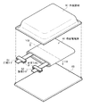
図5および図6は第2の電池の断面構成を表しており、図6では図5に示した巻回電極体40の一部を拡大して示している。この電池は、例えば、上記した第1の電池と同様にリチウムイオン二次電池であり、主に、ほぼ中空円柱状の電池缶31の内部に、セパレータ43を介して正極41と負極42とが巻回された巻回電極体40と、一対の絶縁板32,33とが収納されたものである。この電池缶31を含む電池構造は、円筒型と呼ばれている。
(Second battery)
5 and 6 show a cross-sectional configuration of the second battery. FIG. 6 shows an enlarged part of the spirally
電池缶31は、例えば、上記した第1の電池における電池缶11と同様の金属材料によって構成されており、その一端部は閉鎖されると共に他端部は開放されている。一対の絶縁板32,33は、巻回電極体40を挟み、その巻回周面に対して垂直に延在するように配置されている。
The battery can 31 is made of, for example, the same metal material as that of the battery can 11 in the first battery described above. One end of the battery can 31 is closed and the other end is opened. The pair of insulating plates 32 and 33 are arranged so as to extend perpendicular to the winding peripheral surface with the
電池缶31の開放端部には、電池蓋34と、その内側に設けられた安全弁機構35および熱感抵抗素子(Positive Temperature Coefficient:PTC素子)36とがガスケット37を介してかしめられて取り付けられている。これにより、電池缶31の内部は密閉されている。電池蓋34は、例えば、電池缶31と同様の材料によって構成されている。安全弁機構35は、熱感抵抗素子36を介して電池蓋34と電気的に接続されている。この安全弁機構35では、内部短絡あるいは外部からの加熱などに起因して内圧が一定以上となった場合に、ディスク板35Aが反転して電池蓋34と巻回電極体40との間の電気的接続が切断されるようになっている。熱感抵抗素子36は、温度の上昇に応じて抵抗が増大することによって電流を制限し、大電流に起因する異常な発熱を防止するものである。ガスケット37は、例えば、絶縁材料によって構成されており、その表面にはアスファルトが塗布されている。
A
巻回電極体40の中心には、センターピン44が挿入されていてもよい。この巻回電極体40では、アルミニウムなどによって構成された正極リード45が正極41に接続されており、ニッケルなどによって構成された負極リード46が負極42に接続されている。正極リード45は、安全弁機構35に溶接されて電池蓋34と電気的に接続されており、負極リード46は、電池缶31に溶接されて電気的に接続されている。
A center pin 44 may be inserted in the center of the
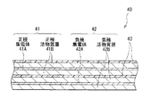
正極41は、例えば、帯状の正極集電体41Aの両面に正極活物質層41Bが設けられたものである。負極42は、上記した負極と同様の構成を有しており、例えば、帯状の負極集電体42Aの両面に負極活物質層42Bが設けられたものである。正極集電体41A、正極活物質層41B、負極集電体42A、負極活物質層42Bおよびセパレータ43の構成、ならびに電解液の組成は、それぞれ上記した第1の電池における正極集電体21A、正極活物質層21B、負極集電体22A、負極活物質層22Bおよびセパレータ23の構成、ならびに電解液の組成と同様である。
In the
この二次電池は、例えば、以下のようにして製造される。 This secondary battery is manufactured as follows, for example.
まず、例えば、上記した第1の電池における正極21および負極22の作製手順と同様の手順により、正極集電体41Aの両面に正極活物質層41Bを形成して正極41を作製すると共に、負極集電体42Aの両面に負極活物質層42Bを形成して負極42を作製する。続いて、正極41に正極リード45を取り付けると共に、負極42に負極リード46を取り付ける。続いて、セパレータ43を介して正極41と負極42とを積層してから巻回させて巻回電極体40を形成し、正極リード45の先端部を安全弁機構35に接続させると共に負極リード46の先端部を電池缶31に接続させたのち、巻回電極体40を一対の絶縁板32,33で挟みながら電池缶31の内部に収納する。続いて、電池缶31の内部に電解液を注入してセパレータ43に含浸させる。最後に、電池缶31の開口端部に電池蓋34、安全弁機構35および熱感抵抗素子36をガスケット37を介してかしめて固定する。これにより、図5および図6に示した二次電池が完成する。
First, for example, the
この二次電池では、充電を行うと、例えば、正極41からリチウムイオンが放出され、セパレータ43に含浸された電解液を介して負極42に吸蔵される。一方、放電を行うと、例えば、負極42からリチウムイオンが放出され、セパレータ43に含浸された電解液を介して正極41に吸蔵される。
In the secondary battery, when charged, for example, lithium ions are released from the
この円筒型の二次電池によれば、負極42が上記した負極と同様の構成を有しているので、サイクル特性を向上させることができる。この二次電池に関する他の効果は、第1の電池と同様である。
According to this cylindrical secondary battery, since the
(第3の電池)
図7は第3の電池の分解斜視構成を表しており、図8は図7に示したVIII−VIII線に沿った断面を拡大して示している。この電池は、例えば、上記した第1の電池と同様にリチウムイオン二次電池であり、主に、フィルム状の外装部材60の内部に、正極リード51および負極リード52が取り付けられた巻回電極体50が収納されたものである。この外装部材60を含む電池構造は、ラミネートフィルム型と呼ばれている。
(Third battery)
FIG. 7 shows an exploded perspective configuration of the third battery, and FIG. 8 shows an enlarged cross section along the line VIII-VIII shown in FIG. This battery is, for example, a lithium ion secondary battery similar to the first battery described above, and is mainly a wound electrode in which a
正極リード51および負極リード52は、例えば、外装部材60の内部から外部に向かって同一方向に導出されている。正極リード51は、例えば、アルミニウムなどの金属材料によって構成されており、負極リード52は、例えば、銅、ニッケルあるいはステンレスなどの金属材料によって構成されている。これらの金属材料は、例えば、薄板状あるいは網目状になっている。
The
外装部材60は、例えば、ナイロンフィルムと、アルミニウム箔と、ポリエチレンフィルムがこの順に貼り合わされたアルミラミネートフィルムによって構成されている。この外装部材60は、例えば、ポリエチレンフィルムが巻回電極体50と対向するように、2枚の矩形型のアルミラミネートフィルムの外縁部同士が融着あるいは接着剤によって互いに接着された構造を有している。
The
外装部材60と正極リード51および負極リード52との間には、外気の侵入を防止するために密着フィルム61が挿入されている。この密着フィルム61は、正極リード51および負極リード52に対して密着性を有する材料によって構成されている。このような材料としては、例えば、ポリエチレン、ポリプロピレン、変性ポリエチレンあるいは変性ポリプロピレンなどのポリオレフィン樹脂が挙げられる。
An
なお、外装部材60は、上記したアルミラミネートフィルムに代えて、他の積層構造を有するラミネートフィルムによって構成されていてもよいし、ポリプロピレンなどの高分子フィルムあるいは金属フィルムによって構成されていてもよい。
In addition, the
巻回電極体50は、セパレータ55および電解質56を介して正極53と負極54とが積層されたのちに巻回されたものであり、その最外周部は保護テープ57によって保護されている。
The
正極53は、例えば、帯状の正極集電体53Aの両面に正極活物質層53Bが設けられたものである。負極54は、上記した負極と同様の構成を有しており、例えば、帯状の負極集電体54Aの両面に負極活物質層54Bが設けられたものである。正極集電体53A、正極活物質層53B、負極集電体54A、負極活物質層54Bおよびセパレータ55の構成は、それぞれ上記した第1の電池における正極集電体21A、正極活物質層21B、負極集電体22A、負極活物質層22Bおよびセパレータ23の構成と同様である。
In the
電解質56は、電解液と、それを保持する高分子化合物とを含んでおり、いわゆるゲル状の電解質である。ゲル状の電解質は、高いイオン伝導率(例えば室温で1mS/cm以上)が得られると共に漏液が防止されるので好ましい。
The
高分子化合物としては、例えば、ポリアクリロニトリル、ポリフッ化ビニリデン、ポリフッ化ビニリデンとポリヘキサフルオロピレンとの共重合体、ポリテトラフルオロエチレン、ポリヘキサフルオロプロピレン、ポリエチレンオキサイド、ポリプロピレンオキサイド、ポリフォスファゼン、ポリシロキサン、ポリ酢酸ビニル、ポリビニルアルコール、ポリメタクリル酸メチル、ポリアクリル酸、ポリメタクリル酸、スチレン−ブタジエンゴム、ニトリル−ブタジエンゴム、ポリスチレンあるいはポリカーボネートなどが挙げられる。これらは単独でも混合されてもよい。中でも、ポリアクリロニトリル、ポリフッ化ビニリデン、ポリヘキサフルオロプロピレンあるいはポリエチレンオキサイドが好ましい。電気化学的に安定だからである。 Examples of the polymer compound include polyacrylonitrile, polyvinylidene fluoride, a copolymer of polyvinylidene fluoride and polyhexafluoropyrene, polytetrafluoroethylene, polyhexafluoropropylene, polyethylene oxide, polypropylene oxide, polyphosphazene, poly Examples thereof include siloxane, polyvinyl acetate, polyvinyl alcohol, polymethyl methacrylate, polyacrylic acid, polymethacrylic acid, styrene-butadiene rubber, nitrile-butadiene rubber, polystyrene, and polycarbonate. These may be used alone or in combination. Among these, polyacrylonitrile, polyvinylidene fluoride, polyhexafluoropropylene or polyethylene oxide is preferable. This is because it is electrochemically stable.
電解液の組成は、第1の電池における電解液の組成と同様である。ただし、この場合の溶媒とは、液状の溶媒だけでなく、電解質塩を解離させることが可能なイオン伝導性を有するものまで含む広い概念である。したがって、イオン伝導性を有する高分子化合物を用いる場合には、その高分子化合物も溶媒に含まれる。 The composition of the electrolytic solution is the same as the composition of the electrolytic solution in the first battery. However, the solvent in this case is not only a liquid solvent but also a broad concept including those having ion conductivity capable of dissociating the electrolyte salt. Accordingly, when a polymer compound having ion conductivity is used, the polymer compound is also included in the solvent.
なお、電解液を高分子化合物に保持させたゲル状の電解質56に代えて、電解液をそのまま用いてもよい。この場合には、電解液がセパレータ55に含浸される。
In place of the
ゲル状の電解質56を備えた二次電池は、例えば、以下の3種類の製造方法によって製造される。
The secondary battery including the
第1の製造方法では、最初に、例えば、第1の電池の製造方法と同様の手順により、正極集電体53Aの両面に正極活物質層53Bを形成して正極53を作製すると共に、負極集電体54Aの両面に負極活物質層54Bを形成して負極54を作製する。続いて、電解液と、高分子化合物と、溶剤とを含む前駆溶液を調製して正極53および負極54に塗布したのち、溶剤を揮発させてゲル状の電解質56を形成する。続いて、正極53に正極リード51を取り付けると共に、負極54に負極リード52を取り付ける。続いて、電解質56が形成された正極53と負極54とをセパレータ55を介して積層させてから長手方向に巻回し、その最外周部に保護テープ57を接着させて巻回電極体50を作製する。最後に、例えば、2枚のフィルム状の外装部材60の間に巻回電極体50を挟み込んだのち、その外装部材60の外縁部同士を熱融着などで接着させて巻回電極体50を封入する。この際、正極リード51および負極リード52と外装部材60との間に、密着フィルム61を挿入する。これにより、図7および図8に示した二次電池が完成する。
In the first manufacturing method, first, the positive electrode
第2の製造方法では、最初に、正極53に正極リード51を取り付けると共に負極54に負極リード52を取り付けたのち、セパレータ55を介して正極53と負極54とを積層してから巻回させると共に最外周部に保護テープ57を接着させて、巻回電極体50の前駆体である巻回体を作製する。続いて、2枚のフィルム状の外装部材60の間に巻回体を挟み込んだのち、一辺の外周縁部を除いた残りの外周縁部を熱融着などで接着させて、袋状の外装部材60の内部に巻回体を収納する。続いて、電解液と、高分子化合物の原料であるモノマーと、重合開始剤と、必要に応じて重合禁止剤などの他の材料とを含む電解質用組成物を調製して袋状の外装部材60の内部に注入したのち、外装部材60の開口部を熱融着などで密封する。最後に、モノマーを熱重合させて高分子化合物とすることにより、ゲル状の電解質56を形成する。これにより、二次電池が完成する。
In the second manufacturing method, first, the
第3の製造方法では、最初に、高分子化合物が両面に塗布されたセパレータ55を用いることを除き、上記した第2の製造方法と同様に、巻回体を作製して袋状の外装部材60の内部に収納する。このセパレータ55に塗布する高分子化合物としては、例えば、フッ化ビニリデンを成分とする重合体、すなわち単独重合体、共重合体あるいは多元共重合体などが挙げられる。具体的には、ポリフッ化ビニリデンや、フッ化ビニリデンおよびヘキサフルオロプロピレンを成分とする二元系共重合体や、フッ化ビニリデン、ヘキサフルオロプロピレンおよびクロロトリフルオロエチレンを成分とする三元系共重合体などである。なお、高分子化合物は、上記したフッ化ビニリデンを成分とする重合体と共に、他の1種あるいは2種以上の高分子化合物を含んでいてもよい。続いて、外装部材60の内部に電解液を注入したのち、その外装部材60の開口部を熱融着などで密封する。最後に、外装部材60に加重をかけながら加熱し、高分子化合物を介してセパレータ55を正極53および負極54に密着させる。これにより、電解液が高分子化合物に含浸し、その高分子化合物がゲル化して電解質56が形成されるため、二次電池が完成する。
In the third production method, a wound body is produced by manufacturing a wound body in the same manner as in the second production method described above, except that the
この第3の製造方法では、第1の製造方法と比較して、二次電池の膨れが抑制される。また、第3の製造方法では、第2の製造方法と比較して、高分子化合物の原料であるモノマーや溶媒などが電解質56中にほとんど残らず、しかも高分子化合物の形成工程が良好に制御されるため、正極53、負極54およびセパレータ55と電解質56との間において十分な密着性が得られる。
In the third manufacturing method, the swollenness of the secondary battery is suppressed as compared with the first manufacturing method. Further, in the third manufacturing method, compared to the second manufacturing method, there are almost no monomers or solvents that are raw materials for the polymer compound in the
このラミネートフィルム型の二次電池によれば、負極54が上記した負極と同様の構成を有しているので、サイクル特性を向上させることができる。この二次電池に関する他の効果は、第1の電池と同様である。
According to this laminate film type secondary battery, since the
本発明の実施例について詳細に説明する。 Examples of the present invention will be described in detail.
(実験例1−1)
以下の手順により、図7および図8に示したラミネートフィルム型の二次電池を製造した。この際、負極54の容量がリチウムの吸蔵および放出に基づいて表されるリチウムイオン二次電池となるようにした。
( Experimental Example 1-1)
The laminate film type secondary battery shown in FIGS. 7 and 8 was manufactured by the following procedure. At this time, a lithium ion secondary battery in which the capacity of the
まず、正極53を作製した。最初に、炭酸リチウム(Li2 CO3 )と炭酸コバルト(CoCO3 )とを0.5:1のモル比で混合したのち、空気中において900℃×5時間の条件で焼成してリチウムコバルト複合酸化物(LiCoO2 )を得た。続いて、正極活物質としてリチウムコバルト複合酸化物91質量部と、導電剤としてグラファイト6質量部と、結着剤としてポリフッ化ビニリデン3質量部とを混合して正極合剤としたのち、N−メチル−2−ピロリドンに分散させてペースト状にし、所定の粘度の正極合剤スラリーとした。最後に、コーティング装置によって帯状のアルミニウム箔(厚さ=12μm)からなる正極集電体53Aの両面に正極合剤スラリーを均一にパターン塗布して乾燥させたのち、ロールプレス機で塗膜を圧縮成型して正極活物質層53Bを形成した。
First, the
次に、負極54を作製した。最初に、偏向式電子ビーム蒸着源を用いた電子ビーム蒸着法によって電解銅箔(厚さ=15μm)の表面にケイ素を堆積し、硝酸で電解銅箔を溶解除去してケイ素膜を残存させたのち、そのケイ素膜をボールミルで粉砕してケイ素粉末を得た。この際、蒸着源として純度99%のケイ素を用い、メジアン径が5μmとなるように粉砕時間を調整した。このメジアン径を調べる場合には、堀場製作所製の粒子径測定装置LA−920を用いた。また、ケイ素を堆積させる際の基板温度および堆積速度を調整して、X線回折によって得られるケイ素の(220)結晶面に起因するピークの強度I1と(111)結晶面に起因するピークの強度I2との強度比I1/I2を0.05とした。このX線回折による分析を行う場合には、リガク電機株式会社製のX線回折装置を用いた。この際、官球としCuKaを用い、官電圧を40kV、官電流を40mA、スキャン方法をθ−2θ法、測定範囲を20°≦2θ≦90°とした。続いて、N−メチル−2−ピロリドンおよびN,N−ジメチルアセトアミドを溶媒とするポリアミック酸溶液を調製した。続いて、負極活物質としてケイ素粉末と、負極結着剤の前駆体であるポリアミック酸溶液とを80:20の乾燥重量比で混合したのち、N−メチル−2−ピロリドンに分散させてペースト状にし、所定の粘度を有する負極合剤スラリーとした。続いて、コーティング装置によって電解銅箔からなる負極集電体54A(厚さ=15μm,算術平均粗さRa=0.2μm)の両面に負極合剤スラリーを均一にパターン塗布して乾燥させたのち、ロールプレス機によって塗膜を圧縮成型した。最後に、真空雰囲気中において400℃×1時間の条件で塗膜を熱処理した。これにより、負極結着剤としてポリイミド(PI)が生成されると共に、そのポリイミドの一部が炭化して、負極活物質層54Bが形成された。この際、負極活物質層54B側から見た負極54の表面の色(明度L*)を調べたところ、その明度L*は45であった。また、20°≦2θ≦90°の計測範囲において、ケイ素の(220)結晶面に起因するピークの強度I1および(111)結晶面に起因するピークの強度I2の和Aに対する他の結晶面に起因するピークの強度の和Bの強度比A/Bを調べたところ、その強度比A/Bは2であった。この明度L*を調べる場合には、横河メータ&インスツルメンツ株式会社製の分光側色計CD100を用いた。また、強度比A/Bを調べる場合には、強度比I1/I2を調べた場合と同様のX線回折装置を用いた。
Next, the
次に、溶媒として炭酸エチレン(EC)と炭酸ジエチル(DEC)とを混合したのち、電解質塩として六フッ化リン酸リチウム(LiPF6 )を溶解させて電解液を調製した。この際、溶媒の組成(EC:DEC)を重量比で50:50とし、電解液中における電解質塩の濃度を1mol/kgとした。 Next, ethylene carbonate (EC) and diethyl carbonate (DEC) were mixed as a solvent, and then lithium hexafluorophosphate (LiPF 6 ) was dissolved as an electrolyte salt to prepare an electrolytic solution. At this time, the composition of the solvent (EC: DEC) was 50:50 by weight, and the concentration of the electrolyte salt in the electrolytic solution was 1 mol / kg.
次に、正極53および負極54と共に電解液を用いて二次電池を組み立てた。最初に、正極集電体53Aの一端にアルミニウム製の正極リード51を溶接すると共に、負極集電体54Aの一端にニッケル製の負極リード52を溶接した。続いて、正極53と、多孔性ポリプロピレンを主成分とするフィルムによって多孔性ポリエチレンを主成分とするフィルムが挟まれた3層構造のセパレータ55(厚さ=23μm)と、負極54と、上記したセパレータ55とをこの順に積層してから長手方向に巻回させたのち、粘着テープからなる保護テープ57で巻き終わり部分を固定して、巻回電極体50の前駆体である巻回体を形成した。続いて、外側から、ナイロンフィルム(厚さ=30μm)と、アルミニウム箔(厚さ=40μm)と、無延伸ポリプロピレンフィルム(厚さ=30μm)とが積層された3層構造のラミネートフィルム(総厚=100μm)からなる外装部材60の間に巻回体を挟み込んだのち、一辺を除く外縁部同士を熱融着して、袋状の外装部材60の内部に巻回体を収納した。続いて、外装部材60の開口部から電解液を注入してセパレータ55に含浸させて巻回電極体50を作製した。最後に、真空雰囲気中において外装部材60の開口部を熱融着して封止することにより、ラミネートフィルム型の二次電池が完成した。この場合には、正極53の容量と負極54の容量との比率を調整して、負極利用率を50%とした。
Next, a secondary battery was assembled using the electrolyte together with the
(実験例1−2〜1−13)
強度比I1/I2を0.05に代えて、0.1(実験例1−2)、0.2(実験例1−3)、0.3(実験例1−4)、0.4(実験例1−5)、0.5(実験例1−6)、0.6(実験例1−7)、0.7(実験例1−8)、0.8(実験例1−9)、0.9(実験例1−10)、1(実験例1−11)、1.2(実験例1−12)、あるいは1.5(実験例1−13)としたことを除き、実験例1−1と同様の手順を経た。この強度比I1/I2を変更する場合には、ケイ素を堆積させる際の基板温度および堆積速度を変化させた。
( Experimental Examples 1-2 to 1-13)
The intensity ratio I1 / I2 is changed to 0.05, and 0.1 ( Experimental example 1-2), 0.2 ( Experimental example 1-3), 0.3 ( Experimental example 1-4), 0.4 ( Experimental Example 1-5), 0.5 ( Experimental Example 1-6), 0.6 ( Experimental Example 1-7), 0.7 ( Experimental Example 1-8), 0.8 ( Experimental Example 1-9) , 0.9 (experimental example 1-10), 1 (experimental example 1-11), except that it has a 1.2 (experimental example 1-12), or 1.5 (experimental example 1-13), experimental The same procedure as in Example 1-1 was performed. When this intensity ratio I1 / I2 was changed, the substrate temperature and deposition rate when silicon was deposited were changed.
(比較例1−1,1−2)
強度比I1/I2を0.05に代えて、0.01(比較例1−1)、あるいは0.03(比較例1−2)としたことを除き、実験例1−1と同様の手順を経た。
(Comparative Examples 1-1 and 1-2)
A procedure similar to that of Experimental Example 1-1 except that the intensity ratio I1 / I2 is changed to 0.05 and is set to 0.01 (Comparative Example 1-1) or 0.03 (Comparative Example 1-2). It went through.
これらの実験例1−1〜1−13および比較例1−1,1−2の二次電池についてサイクル特性を調べたところ、表1および図9に示した結果が得られた。 When the cycle characteristics of the secondary batteries of Experimental Examples 1-1 to 1-13 and Comparative Examples 1-1 and 1-2 were examined, the results shown in Table 1 and FIG. 9 were obtained.
サイクル特性を調べる際には、電池状態を安定化させるために23℃の雰囲気中で1サイクル充放電させてから、同雰囲気中で充放電させて2サイクル目の放電容量を測定し、引き続き同雰囲気中で99サイクル充放電させて101サイクル目の放電容量を測定したのち、放電容量維持率(%)=(101サイクル目の放電容量/2サイクル目の放電容量)×100を算出した。この際、1サイクルの充放電条件としては、3mA/cm2 の定電流密度で電池電圧が4.2Vに到達するまで充電し、引き続き4.2Vの定電圧で電流密度が0.3mA/cm2 に到達するまで充電したのち、3mA/cm2 の定電流密度で電池電圧が2.5Vに到達するまで放電した。 When investigating cycle characteristics, charge and discharge for one cycle in an atmosphere at 23 ° C. to stabilize the battery state, and then charge and discharge in the same atmosphere to measure the discharge capacity for the second cycle. After charging and discharging 99 cycles in the atmosphere and measuring the discharge capacity at the 101st cycle, the discharge capacity retention ratio (%) = (discharge capacity at the 101st cycle / discharge capacity at the second cycle) × 100 was calculated. At this time, as a charge / discharge condition for one cycle, the battery was charged at a constant current density of 3 mA / cm 2 until the battery voltage reached 4.2 V, and then the current density was 0.3 mA / cm at a constant voltage of 4.2 V. After charging until reaching 2 , the battery was discharged at a constant current density of 3 mA / cm 2 until the battery voltage reached 2.5V.
なお、サイクル特性を調べる際の手順および条件は、以降の一連の実験例および比較例についても同様である。 The procedure and conditions for examining the cycle characteristics are the same for the series of experimental examples and comparative examples that follow.
表1および図9に示したように、負極結着剤としてポリイミドを用いた場合には、強度比I1/I2が大きくなるにしたがって、放電容量維持率は急激に増加したのちに緩やかに減少してほぼ一定となった。この場合には、強度比I1/I2が0.05以上であると放電容量維持率が大幅に増加すると共に、0.2以上1以下であると放電容量維持率がより増加し、ここでは80%を上回る傾向を示した。 As shown in Table 1 and FIG. 9, when polyimide was used as the negative electrode binder, the discharge capacity maintenance rate increased rapidly and then gradually decreased as the strength ratio I1 / I2 increased. Almost constant. In this case, when the intensity ratio I1 / I2 is 0.05 or more, the discharge capacity retention rate is significantly increased, and when the intensity ratio I1 / I2 is 0.2 or more and 1 or less, the discharge capacity retention rate is further increased. The tendency which exceeded% was shown.
これらの結果は、強度比I1/I2が上記した範囲であると、放電容量維持率に好影響を及ぼすケイ素の安定な結晶面(稠密な面)が得られ、その結晶状態が適正化されることを表している。詳細には、強度比I1/I2が小さすぎると、ケイ素の安定な結晶面(稠密な面)が少ないため、初期充電時においてリチウムイオンが負極54に吸蔵される際に、そのリチウムイオンがケイ素の不安定な結晶面に集中し、負極54が反応しやすくなる。これにより、電解液が分解されやすくなると共に、負極活物質層54Bが崩落しやすくなる。一方、強度比I1/I2が大きすぎると、ケイ素の安定な結晶面が多いため、電解液が分解しにくいと共に負極活物質層54Bが崩落しにくいが、面成長を促すために熱処理した場合に負極活物質中に欠陥が生じやすいため、負極活物質層54Bが崩落しやすくなる。
These results show that when the intensity ratio I1 / I2 is in the above range, a stable crystal plane (dense plane) of silicon that has a favorable effect on the discharge capacity retention rate is obtained, and the crystal state is optimized. Represents that. Specifically, if the intensity ratio I1 / I2 is too small, there are few stable crystal planes (dense planes) of silicon. Therefore, when lithium ions are occluded in the
これらのことから、本発明の二次電池では、負極結着剤としてポリイミドを用いた場合に強度比I1/I2を0.05以上とすることにより、サイクル特性が向上することが確認された。この場合には、強度比I1/I2を0.2以上1以下とすれば、特性がより向上することも確認された。 From these results, it was confirmed that in the secondary battery of the present invention, when polyimide was used as the negative electrode binder, the cycle characteristics were improved by setting the strength ratio I1 / I2 to 0.05 or more. In this case, it was also confirmed that the characteristics were further improved if the intensity ratio I1 / I2 was set to 0.2 or more and 1 or less.
(実験例2−1〜2−7)
ポリアミック酸溶液に代えてポリアミド溶液を用い、負極結着剤としてポリアミド(PA)を生成したことを除き、実験例1−1〜1−4,1−7,1−11,1−12と同様の手順を経た。
( Experimental examples 2-1 to 2-7)
Similar to Experimental Examples 1-1 to 1-4, 1-7, 1-11, and 1-12, except that a polyamide solution was used instead of the polyamic acid solution and polyamide (PA) was produced as a negative electrode binder. I went through the procedure.
(比較例2−1,2−2)
実験例2−1〜2−7と同様に負極結着剤としてポリアミドを生成したことを除き、比較例1−1,1−2と同様の手順を経た。
(Comparative Examples 2-1 and 2-2)
The same procedure as Comparative Examples 1-1 and 1-2 was performed except that polyamide was produced as a negative electrode binder as in Experimental Examples 2-1 to 2-7.
これらの実験例2−1〜2−7および比較例2−1,2−2の二次電池についてサイクル特性を調べたところ、表2および図10に示した結果が得られた。 When the cycle characteristics of the secondary batteries of Experimental Examples 2-1 to 2-7 and Comparative Examples 2-1 and 2-2 were examined, the results shown in Table 2 and FIG. 10 were obtained.
表2および図10に示したように、負極結着剤としてポリアミドを用いた場合においても、ポリイミドを用いた場合(表1)とほぼ同様の結果が得られた。すなわち、強度比I1/I2が大きくなるにしたがって、放電容量維持率は急激に増加したのちに緩やかに減少した。この場合には、強度比I1/I2が0.05以上であると放電容量維持率が大幅に増加すると共に、0.2以上1以下であると放電容量維持率がより増加する傾向を示した。 As shown in Table 2 and FIG. 10, even when polyamide was used as the negative electrode binder, almost the same results were obtained as when polyimide was used (Table 1). That is, as the intensity ratio I1 / I2 increased, the discharge capacity retention rate increased rapidly and then gradually decreased. In this case, when the intensity ratio I1 / I2 was 0.05 or more, the discharge capacity retention rate increased significantly, and when it was 0.2 or more and 1 or less, the discharge capacity retention rate tended to increase more. .
これらのことから、本発明の二次電池では、負極結着剤としてポリアミドを用いた場合においても、強度比I1/I2を0.05以上とすることでサイクル特性が向上し、0.2以上1以下とすれば特性がより向上することが確認された。 For these reasons, in the secondary battery of the present invention, even when polyamide is used as the negative electrode binder, the cycle characteristics are improved by setting the strength ratio I1 / I2 to 0.05 or more, and 0.2 or more. It was confirmed that the characteristics were further improved when the ratio was 1 or less.
(実験例3−1〜3−7)
ポリアミック酸溶液に代えてポリアミドイミド溶液を用い、負極結着剤としてポリアミドイミド(PAI)を生成したことを除き、実験例1−1〜1−4,1−7,1−11,1−12と同様の手順を経た。
( Experimental examples 3-1 to 3-7)
Experimental Examples 1-1 to 1-4, 1-7, 1-11, and 1-12 except that a polyamideimide solution was used instead of the polyamic acid solution and polyamideimide (PAI) was produced as a negative electrode binder. The same procedure was followed.
(比較例3−1,3−2)
実験例3−1〜3−7と同様に負極結着剤としてポリアミドイミドを生成したことを除き、比較例1−1,1−2と同様の手順を経た。
(Comparative Examples 3-1 and 3-2)
The procedure was similar to that of Comparative Examples 1-1 and 1-2 except that polyamideimide was produced as a negative electrode binder as in Experimental Examples 3-1 to 3-7.
これらの実験例3−1〜3−7および比較例3−1,3−2の二次電池についてサイクル特性を調べたところ、表3および図11に示した結果が得られた。 When the cycle characteristics of the secondary batteries of Experimental Examples 3-1 to 3-7 and Comparative Examples 3-1 and 3-2 were examined, the results shown in Table 3 and FIG. 11 were obtained.
表3および図11に示したように、負極結着剤としてポリアミドイミドを用いた場合においても、ポリイミドを用いた場合(表1)とほぼ同様の結果が得られた。すなわち、強度比I1/I2が大きくなるにしたがって、放電容量維持率は急激に増加したのちに緩やかに減少した。この場合には、強度比I1/I2が0.05以上であると放電容量維持率が大幅に増加すると共に、0.2以上1以下であると放電容量維持率がより増加する傾向を示した。 As shown in Table 3 and FIG. 11, in the case of using polyamideimide as the negative electrode binder, the same results as in the case of using polyimide (Table 1) were obtained. That is, as the intensity ratio I1 / I2 increased, the discharge capacity retention rate increased rapidly and then gradually decreased. In this case, when the intensity ratio I1 / I2 was 0.05 or more, the discharge capacity retention rate increased significantly, and when it was 0.2 or more and 1 or less, the discharge capacity retention rate tended to increase more. .
これらのことから、本発明の二次電池では、負極結着剤としてポリアミドイミドを用いた場合においても、強度比I1/I2を0.05以上とすることでサイクル特性が向上し、0.2以上1以下とすれば特性がより向上することが確認された。 From these, in the secondary battery of the present invention, even when polyamideimide is used as the negative electrode binder, the cycle characteristics are improved by setting the strength ratio I1 / I2 to 0.05 or more, and 0.2 It was confirmed that the characteristics were further improved when the ratio was 1 or less.
(実験例4−1〜4−8)
負極結着剤としてポリイミドに代えてポリフッ化ビニリデン(PVDF)を用いたことを除き、実験例1−1〜1−4,1−7,1−9,1−11,1−12と同様の手順を経た。
( Experimental examples 4-1 to 4-8)
Similar to Experimental Examples 1-1 to 1-4, 1-7, 1-9, 1-11, 1-12 except that polyvinylidene fluoride (PVDF) was used as the negative electrode binder instead of polyimide. Goed through the procedure.
(比較例4−1,4−2)
実験例4−1〜4−8と同様に負極結着剤としてポリフッ化ビニリデンを用いたことを除き、比較例1−1,1−2と同様の手順を経た。
(Comparative Examples 4-1 and 4-2)
The procedure was similar to that of Comparative Examples 1-1 and 1-2, except that polyvinylidene fluoride was used as the negative electrode binder as in Experimental Examples 4-1 to 4-8.
これらの実験例4−1〜4−8および比較例4−1,4−2の二次電池についてサイクル特性を調べたところ、表4および図12に示した結果が得られた。 When the cycle characteristics of the secondary batteries of Experimental Examples 4-1 to 4-8 and Comparative Examples 4-1 and 4-2 were examined, the results shown in Table 4 and FIG. 12 were obtained.
表4および図12に示したように、負極結着剤としてポリフッ化ビニリデンを用いた場合においても、ポリイミドを用いた場合(表1)とほぼ同様の結果が得られた。すなわち、強度比I1/I2が大きくなるにしたがって、放電容量維持率は急激に増加したのちに緩やかに減少した。この場合には、強度比I1/I2が0.05以上であると放電容量維持率が大幅に増加すると共に、0.2以上1以下であると放電容量維持率がより増加し、ここでは75%を上回る傾向を示した。 As shown in Table 4 and FIG. 12, in the case of using polyvinylidene fluoride as the negative electrode binder, the same results as in the case of using polyimide (Table 1) were obtained. That is, as the intensity ratio I1 / I2 increased, the discharge capacity retention rate increased rapidly and then gradually decreased. In this case, when the intensity ratio I1 / I2 is 0.05 or more, the discharge capacity maintenance ratio increases significantly, and when it is 0.2 or more and 1 or less, the discharge capacity maintenance ratio further increases. Here, 75 The tendency which exceeded% was shown.
これらのことから、本発明の二次電池では、負極結着剤としてポリフッ化ビニリデンを用いた場合においても、強度比I1/I2を0.05以上とすることでサイクル特性が向上し、0.2以上1以下とすれば特性がより向上することが確認された。 Therefore, in the secondary battery of the present invention, even when polyvinylidene fluoride is used as the negative electrode binder, the cycle characteristics are improved by setting the strength ratio I1 / I2 to 0.05 or more. It was confirmed that the characteristics were further improved when the ratio was 2 or more and 1 or less.
ここで、表1〜表4の結果から、負極結着剤の種類の違いに着目すると、ポリイミド、ポリアミドあるいはポリアミドイミドを用いた実験例1−7,2−5,3−5では、ポリフッ化ビニリデンを用いた実験例4−5よりも放電容量維持率が高くなった。このことから、負極結着剤としてポリイミド、ポリアミドあるいはポリイミドアミドを用いれば、サイクル特性がより向上することが確認された。 From the results of Table 1 to Table 4, when attention is paid to the type of difference in the anode binder, in Examples 1-7,2-5,3-5 using polyimide, polyamide or polyamideimide, polyvinylidene fluoride The discharge capacity retention rate was higher than in Experimental Example 4-5 using vinylidene. From this, it was confirmed that when polyimide, polyamide or polyimide amide is used as the negative electrode binder, the cycle characteristics are further improved.
(実験例5−1〜5−18)
負極活物質のメジアン径を5μmに変えて、0.05μm(実験例5−1)、0.08μm(実験例5−2)、0.1μm(実験例5−3)、0.3μm(実験例5−4)、0.5μm(実験例5−5)、1μm(実験例5−6)、2μm(実験例5−7)、3μm(実験例5−8)、4μm(実験例5−9)、8μm(実験例5−10)、10μm(実験例5−11)、13μm(実験例5−12)、15μm(実験例5−13)、20μm(実験例5−14)、25μm(実験例5−15)、30μm(実験例5−16)、35μm(実験例5−17)、あるいは40μm(実験例5−18)としたことを除き、実験例1−7と同様の手順を経た。この負極活物質のメジアン径を変更する場合には、ケイ素膜の粉砕時間を変化させた。
( Experimental examples 5-1 to 5-18)
Changing the median diameter of the negative electrode active material to 5 μm, 0.05 μm ( Experimental example 5-1), 0.08 μm ( Experimental example 5-2), 0.1 μm ( Experimental example 5-3), 0.3 μm ( experiment ) Example 5-4), 0.5 μm ( Experimental Example 5-5), 1 μm ( Experimental Example 5-6), 2 μm ( Experimental Example 5-7), 3 μm ( Experimental Example 5-8), 4 μm ( Experimental Example 5- 9), 8 μm ( Experimental Example 5-10), 10 μm ( Experimental Example 5-11), 13 μm ( Experimental Example 5-12), 15 μm ( Experimental Example 5-13), 20 μm ( Experimental Example 5-14), 25 μm ( experimental example 5-15), 30 [mu] m (experimental example 5-16), 35 [mu] m (experimental example 5-17), or except that a 40 [mu] m (experimental example 5-18), the same procedure as in experimental example 1-7 Passed. When changing the median diameter of the negative electrode active material, the pulverization time of the silicon film was changed.
これらの実験例5−1〜5−18の二次電池についてサイクル特性を調べたところ、表5および図13に示した結果が得られた。 When the cycle characteristics of the secondary batteries of Experimental Examples 5-1~5-18, the results shown in Table 5 and FIG. 13 were obtained.
表5および図13に示したように、メジアン径が大きくなるにしたがって、放電容量維持率は急激に増加したのちに緩やかに減少した。この場合には、メジアン径が0.1μm以上30μm以下であると放電容量維持率が高くなり、ここでは70%を上回る傾向を示した。また、メジアン径が1μm以上20μm以下であると放電容量維持率がより高くなり、ここでは80%を上回る傾向を示した。 As shown in Table 5 and FIG. 13, as the median diameter increased, the discharge capacity retention rate increased rapidly and then gradually decreased. In this case, when the median diameter was 0.1 μm or more and 30 μm or less, the discharge capacity retention rate increased, and here, the tendency of exceeding 70% was shown. Further, when the median diameter is 1 μm or more and 20 μm or less, the discharge capacity retention rate is higher, and here, the tendency to exceed 80% is shown.
この結果は、メジアン径が上記した範囲であると、放電容量維持率に好影響を及ぼす負極活物質の粒子の粒径が適正化されることを表している。詳細には、メジアン径が小さすぎると、負極活物質の表面積が大きくなるため、電解液が分解しやすくなる。一方、メジアン径が大きすぎると、負極活物質の結着性が低くなるため、負極活物質層54Bが崩落しやすくなる。
This result indicates that when the median diameter is in the above-described range, the particle diameter of the negative electrode active material particles having a positive effect on the discharge capacity retention rate is optimized. Specifically, when the median diameter is too small, the surface area of the negative electrode active material is increased, so that the electrolytic solution is easily decomposed. On the other hand, if the median diameter is too large, the binding property of the negative electrode active material is lowered, and the negative electrode
これらのことから、本発明の二次電池では、負極活物質のメジアン径を0.1μm以上30μm以下とすることにより、サイクル特性がより向上することが確認された。この場合には、負極活物質のメジアン径を1μm以上20μm以下とすれば、特性がさらに向上することも確認された。 From these facts, it was confirmed that in the secondary battery of the present invention, the cycle characteristics were further improved by setting the median diameter of the negative electrode active material to 0.1 μm or more and 30 μm or less. In this case, it was also confirmed that the characteristics were further improved by setting the median diameter of the negative electrode active material to 1 μm or more and 20 μm or less.
(実験例6−1〜6−5)
熱処理温度を400℃に代えて、500℃(実験例6−1)、600℃(実験例6−2)、700℃(実験例6−3)、800℃(実験例6−4)、あるいは900℃(実験例6−5)としたことを除き、実験例1−7と同様の手順を経た。
( Experimental examples 6-1 to 6-5)
Instead of the heat treatment temperature of 400 ° C., 500 ° C. ( Experimental Example 6-1), 600 ° C. ( Experimental Example 6-2), 700 ° C. ( Experimental Example 6-3), 800 ° C. ( Experimental Example 6-4), or A procedure similar to that of Experimental Example 1-7 was performed, except that the temperature was 900 ° C. ( Experimental Example 6-5).
これらの実験例6−1〜6−5の二次電池についてサイクル特性を調べたところ、表6に示した結果が得られた。 When the cycle characteristics of the secondary batteries of Experimental Examples 6-1 to 6-5, the results shown in Table 6 were obtained.
表6に示したように、熱処理温度が高くなるにしたがって、放電容量維持率は増加したのちにやや減少した。この場合には、熱処理温度が800℃以下であると、熱処理温度が高くなるにしたがって放電容量維持率が高くなる傾向を示した。この結果は、負極結着剤として用いたポリイミドの分解温度が約500℃であることから、熱処理温度が400°以上になると、負極結着剤であるポリイミドの炭化度が大きくなるため、負極の導電率が高くなることを表している。 As shown in Table 6, as the heat treatment temperature increased, the discharge capacity retention rate increased slightly and then decreased slightly. In this case, when the heat treatment temperature was 800 ° C. or lower, the discharge capacity retention rate tended to increase as the heat treatment temperature increased. Since the decomposition temperature of the polyimide used as the negative electrode binder is about 500 ° C., the carbonization degree of the polyimide, which is the negative electrode binder, increases when the heat treatment temperature is 400 ° C. or higher. This represents an increase in conductivity.
これらのことから、本発明の二次電池では、熱処理温度を高くすれば、サイクル特性がより向上することが確認された。 From these facts, it was confirmed that in the secondary battery of the present invention, the cycle characteristics were further improved by increasing the heat treatment temperature.
(実験例7−1〜7−8)
負極活物質層54B中に負極導電剤として鱗片状の人造黒鉛(メジアン径=5μm:実験例7−1〜7−4)あるいはカーボンブラック(メジアン径=5μm:実験例7−5〜7−8)を加えたことを除き、実験例1−4,1−7,1−9,1−12と同様の手順を経た。この際、人造黒鉛の添加量を10重量%とし、カーボンブラックの添加量を2重量%とした。この「10重量%」とは、負極活物質と負極結着剤とを併せて100重量%とした場合に、その10重量%に相当する分量だけ負極導電剤を加えたという意味であり、「2重量%」についても同様である。
( Experimental examples 7-1 to 7-8)
Scale-like artificial graphite (median diameter = 5 μm: Experimental example 7-1 to 7-4) or carbon black (median diameter = 5 μm: experimental example 7-5 to 7-8) as the negative electrode conductive agent in the negative electrode
これらの実験例7−1〜7−8の二次電池についてサイクル特性を調べたところ、表7に示した結果が得られた。 When the cycle characteristics of the secondary batteries of Experimental Examples 7-1 to 7-8 were examined, the results shown in Table 7 were obtained.
表7に示したように、負極導電剤として人造黒鉛あるいはカーボンブラックを加えた実験例7−1〜7−8では、それらを加えなかった実験例1−4,1−7,1−9,1−12よりも放電容量維持率が高くなった。 As shown in Table 7, in Experimental Examples 7-1 to 7-8 in which artificial graphite or carbon black was added as the negative electrode conductive agent, Experimental Examples 1-4, 1-7, 1-9, The discharge capacity retention rate was higher than 1-12.
これらのことから、本発明の二次電池では、負極活物質層中に負極導電剤を含有させれば、サイクル特性がより向上することが確認された。 From these things, in the secondary battery of this invention, if the negative electrode electrically conductive agent was contained in the negative electrode active material layer, it was confirmed that cycling characteristics improve more.
(実験例8−1〜8−4)
負極集電体54Aの表面の算術平均粗さRaを0.2μmに代えて、0.05μm(実験例8−1)、0.1μm(実験例8−2)、0.3μm(実験例8−3)、あるいは0.4μm(実験例8−4)としたことを除き、実験例1−7と同様の手順を経た。
( Experimental examples 8-1 to 8-4)
The arithmetic average roughness Ra of the surface of the negative electrode
これらの実験例8−1〜8−4の二次電池についてサイクル特性を調べたところ、表8および図14に示した結果が得られた。 When the cycle characteristics of the secondary batteries of Experimental Examples 8-1 to 8-4, the results shown in Table 8 and FIG. 14 were obtained.
表8および図14に示したように、算術平均粗さRaが大きくなるにしたがって、放電容量維持率は増加したのちに一定となった。この場合には、算術平均粗さRaが0.2μm以上になると放電容量維持率が大幅に増加する傾向を示した。 As shown in Table 8 and FIG. 14, as the arithmetic average roughness Ra increases, the discharge capacity retention rate increases and becomes constant. In this case, when the arithmetic average roughness Ra was 0.2 μm or more, the discharge capacity retention rate tended to increase significantly.
これらのことから、本発明の二次電池では、負極集電体の表面の算術平均粗さRaを0.2μm以上とすれば、サイクル特性がより向上することが確認された。 From these facts, in the secondary battery of the present invention, it was confirmed that the cycle characteristics were further improved when the arithmetic average roughness Ra of the surface of the negative electrode current collector was 0.2 μm or more.
(実験例9−1〜9−9)
負極利用率を50%に代えて、10%(実験例9−1)、20%(実験例9−2)、30%(実験例9−3)、40%(実験例9−4)、60%(実験例9−5)、70%(実験例9−6)、80%(実験例9−7)、90%(実験例9−8)、あるいは100%(実験例9−9)としたことを除き、実験例1−7と同様の手順を経た。この負極利用率を変更する場合には、正極53の容量と負極54の容量との比率を変化させた。
( Experimental examples 9-1 to 9-9)
10% ( Experimental Example 9-1), 20% ( Experimental Example 9-2), 30% ( Experimental Example 9-3), 40% ( Experimental Example 9-4) 60% ( Experimental Example 9-5), 70% ( Experimental Example 9-6), 80% ( Experimental Example 9-7), 90% ( Experimental Example 9-8), or 100% ( Experimental Example 9-9) Except for this, the same procedure as in Experimental Example 1-7 was performed. In changing the negative electrode utilization rate, the ratio of the capacity of the
これらの実験例9−1〜9−9の二次電池についてサイクル特性を調べたところ、表9および図15に示した結果が得られた。 When the cycle characteristics of the secondary batteries of Experimental Examples 9-1~9-9, the results shown in Table 9 and FIG. 15 were obtained.
なお、実験例9−1〜9−9の二次電池については、サイクル特性だけでなく、初期充放電特性も調べた。この初期充放電特性を調べる際には、電池状態を安定化させるために23℃の雰囲気中で1サイクル充放電させてから、同雰囲気中で充電させて充電容量を測定し、引き続き同雰囲気中で放電させて放電容量を測定したのち、初期効率(%)=(放電容量/充電容量)×100を算出した。この際、充放電条件としては、1mA/cm2 の定電流密度で電流値が0.05mAに絞られるまで定電圧充電したのち、1mA/cm2 の定電流密度で電池電圧が1.5Vに到達するまで放電した。 For the secondary batteries of Experimental Examples 9-1 to 9-9, not only the cycle characteristics but also the initial charge / discharge characteristics were examined. When investigating the initial charge / discharge characteristics, in order to stabilize the battery state, the battery was charged and discharged for one cycle in an atmosphere at 23 ° C., then charged in the same atmosphere, and the charge capacity was measured. After discharging, the discharge capacity was measured, and the initial efficiency (%) = (discharge capacity / charge capacity) × 100 was calculated. In this case, as the charge and discharge conditions, after the current value is constant-voltage charge until the throttled 0.05mA at a constant current density of 1 mA / cm 2, the constant current density in the battery voltage of 1 mA / cm 2 is 1.5V Discharged until it reached.
表9および図15に示したように、負極利用率が高くなるにしたがって、放電容量維持率は緩やかに減少したのちに急激に減少し、一方、初期効率は急激に増加したのちに緩やかに増加した。この場合には、負極利用率が20%以上80%以下であると、高い放電容量維持率および初期効率が得られ、いずれも80%を上回る傾向を示した。また、負極利用率が30%以上70%以下であると、放電容量維持率および初期効率がより高くなった。 As shown in Table 9 and FIG. 15, as the negative electrode utilization rate increases, the discharge capacity maintenance rate decreases rapidly and then decreases rapidly, while the initial efficiency increases rapidly and then increases gradually. did. In this case, when the negative electrode utilization rate was 20% or more and 80% or less, a high discharge capacity retention rate and initial efficiency were obtained, and both showed a tendency to exceed 80%. Further, when the negative electrode utilization rate was 30% or more and 70% or less, the discharge capacity retention rate and the initial efficiency were further increased.
これらのことから、本発明の二次電池では、負極利用率を20%以上80%以下とすれば、良好なサイクル特性だけでなく良好な初期充放電特性も得られることが確認された。この場合には、負極利用率を30%以上70%以下とすれば、特性がより向上することも確認された。 From these results, it was confirmed that in the secondary battery of the present invention, not only good cycle characteristics but also good initial charge / discharge characteristics can be obtained when the negative electrode utilization rate is 20% or more and 80% or less. In this case, it was also confirmed that the characteristics were further improved if the negative electrode utilization rate was 30% or more and 70% or less.
(実験例10−1)
溶媒としてECに代えて、化2に示したハロゲンを有する環状炭酸エステルであるである4−フルオロ−1,3−ジオキソラン−2−オン(FEC)を用いたことを除き、実験例1−7と同様の手順を経た。
( Experimental example 10-1)
Experimental Example 1-7, except that 4-fluoro-1,3-dioxolan-2-one (FEC), which is a cyclic carbonate having a halogen shown in
(実験例10−2)
電解質塩として四フッ化ホウ酸リチウム(LiBF4 )を加えると共に、酸無水物としてスルホ安息香酸無水物(SBAH)を加えたことを除き、実験例1−7と同様の手順を経た。この際、電解液中における六フッ化ホウ酸リチウムの濃度を1mol/kgとしたまま、電解液中における四フッ化ホウ酸リチウムの濃度を0.05mol/kgとした。また、溶媒中におけるSBAHの含有量を1重量%とした。この「重量%」とは、溶媒全体を100重量%とした場合に、その10重量%に相当する分量だけSBAHを加えたという意味である。
( Experimental example 10-2)
A procedure similar to that of Experimental Example 1-7 was performed except that lithium tetrafluoroborate (LiBF 4 ) was added as an electrolyte salt and sulfobenzoic anhydride (SBAH) was added as an acid anhydride. At this time, the concentration of lithium tetrafluoroborate in the electrolyte was 0.05 mol / kg while the concentration of lithium hexafluoroborate in the electrolyte was 1 mol / kg. The SBAH content in the solvent was 1% by weight. “Wt%” means that SBAH is added in an amount corresponding to 10% by weight when the entire solvent is 100% by weight.
(実験例10−3)
溶媒として炭酸プロピレン(PC)を加えたことを除き、実験例10−2と同様の手順を経た。この際、溶媒の組成(PC:FEC:DEC)を重量比で20:30:50とした。
( Experimental example 10-3)
A procedure similar to that in Experimental Example 10-2 was performed except that propylene carbonate (PC) was added as a solvent. At this time, the composition of the solvent (PC: FEC: DEC) was set to 20:30:50 by weight.
(実験例10−4)
溶媒として化2に示したハロゲンを有する環状炭酸エステルである4,5−ジフルオロ−1,3−ジオキソラン−2−オン(DFEC)を加えたことを除き、実験例10−3と同様の手順を経た。この際、溶媒の組成(PC:FEC:DFEC:DEC)を重量比で30:10:10:50とした。
( Experimental example 10-4)
Except that 4,5-difluoro-1,3-dioxolan-2-one (DFEC), which is a cyclic carbonate having a halogen shown in
(実験例10−5)
溶媒としてFECに代えてDFECを加えたことを除き、実験例10−3と同様の手順を経た。この際、溶媒の組成(PC:DFEC:DEC)を重量比で40:10:50とした。
( Experimental Example 10-5)
A procedure similar to that of Experimental Example 10-3 was performed except that DFEC was added instead of FEC as a solvent. At this time, the composition of the solvent (PC: DFEC: DEC) was 40:10:50 by weight.
これらの実験例10−1〜10−5の二次電池についてサイクル特性を調べたところ、表10に示した結果が得られた。 When the cycle characteristics of the secondary batteries of Experimental Examples 10-1 to 10-5 were examined, the results shown in Table 10 were obtained.
表10に示したように、電解液が他の溶媒(FEC等)、他の電解質塩(四フッ化ホウ酸リチウム)、あるいは酸無水物(SBAH)を含有する実験例10−1〜10−5では、それらを含有しない実験例1−7よりも放電容量維持率が高くなった。この場合には、溶媒がDFECを含有する場合において、FECを含有する場合よりも電容量維持率が高くなる傾向を示した。 As shown in Table 10, Experimental Examples 10-1 to 10- in which the electrolytic solution contains another solvent (FEC or the like), another electrolyte salt (lithium tetrafluoroborate), or an acid anhydride (SBAH). In No. 5, the discharge capacity retention rate was higher than in Experimental Examples 1-7 not containing them. In this case, when the solvent contained DFEC, the capacity retention rate tended to be higher than when the solvent contained FEC.
これらのことから、本発明の二次電池では、溶媒の組成や電解質塩の種類を変更した場合においてもサイクル特性が向上すると共に、電解液に他の溶媒および電解質塩や酸無水物を加えれば特性がより向上することも確認された。また、溶媒に化2に示したハロゲンを有する炭酸エステルを含有させれば特性が向上すると共に、ハロゲンの数が多いほど特性がより向上することも確認された。
From these facts, in the secondary battery of the present invention, the cycle characteristics are improved even when the composition of the solvent and the type of the electrolyte salt are changed, and other solvents, electrolyte salts and acid anhydrides can be added to the electrolytic solution. It was also confirmed that the characteristics were further improved. In addition, it was confirmed that the characteristics were improved by adding a carbonic acid ester having halogen shown in
なお、ここでは溶媒が化1に示したハロゲンを有する鎖状炭酸エステルを含有する場合の結果を示していないが、それは化2に示したハロゲンを有する環状炭酸エステルと同様の被膜形成能力を有することから、化1に示したハロゲンを有する鎖状炭酸エステルを含有する場合においても同様の結果が得られることは明らかである。
In addition, although the result in the case where the solvent contains a chain carbonate having a halogen shown in
(実験例11−1〜11−20)
負極54の表面の色(明度L*)を45に代えて、1(実験例11−1)、3(実験例11−2)、5(実験例11−3)、8(実験例11−4)、8.5(実験例11−5)、10(実験例11−6)、15(実験例11−7)、20(実験例11−8)、25(実験例11−9)、30(実験例11−10)、35(実験例11−11)、40(実験例11−12)、50(実験例11−13)、55(実験例11−14)、60(実験例11−15)、65(実験例11−16)、70(実験例11−17)、75.5(実験例11−18)、80(実験例11−19)、あるいは82(実験例11−20)としたことを除き、実験例1−7と同様の手順を経た。この明度L*を変更する場合には、負極活物質層54Bを形成する際の圧縮圧(いわゆるプレス圧)を変化させた。
( Experimental examples 11-1 to 11-20)
The surface color (lightness L *) of the
これらの実験例11−1〜11−20の二次電池についてサイクル特性を調べたところ、表11および図16に示した結果が得られた。 When the cycle characteristics of the secondary batteries of Experimental Examples 11-1~11-20, the results shown in Table 11 and FIG. 16 were obtained.
表11および図16に示したように、負極結着剤としてポリイミドを用いた場合には、明度L*が大きくなるにしたがって、放電容量維持率は急激に増加したのちに緩やかに減少した。この場合には、明度L*が8.5以上75.5以下であると放電容量維持率が高くなり、ここでは80%を上回ると共に、30以上60以下であると放電容量維持率がより高くなる傾向を示した。 As shown in Table 11 and FIG. 16, when polyimide was used as the negative electrode binder, as the lightness L * increased, the discharge capacity retention rate increased rapidly and then gradually decreased. In this case, when the lightness L * is 8.5 or more and 75.5 or less, the discharge capacity maintenance rate is high. Showed a tendency to become.
これらのことから、本発明の二次電池では、負極54の表面の色(明度L*)を8.5以上75.5以下とすればサイクル特性がより向上し、30以上60以下とすれば特性がさらに向上することが確認された。
For these reasons, in the secondary battery of the present invention, if the color (lightness L *) of the
(実験例12−1〜12−12)
ポリアミック酸溶液に代えてポリアミド溶液を用い、負極結着剤としてポリアミドを生成したことを除き、実験例11−1,11−3〜11−5,11−8〜11−10,11−12,11−15,11−16,11−18,11−19と同様の手順を経た。
( Experimental examples 12-1 to 12-12)
Experimental Examples 11-1, 11-3 to 11-5, 11-8 to 11-10, 11-12, except that a polyamide solution was used instead of the polyamic acid solution, and polyamide was produced as a negative electrode binder. The same procedures as in 11-15, 11-16, 11-18, and 11-19 were performed.
これらの実験例12−1〜12−12の二次電池についてサイクル特性を調べたところ、表12および図17に示した結果が得られた。 When the cycle characteristics of the secondary batteries of Experimental Examples 12-1~12-12, the results shown in Table 12 and Figure 17 it was obtained.
表12および図17に示したように、負極結着剤としてポリアミドを用いた場合においても、ポリイミドを用いた場合(表11)と同様の結果が得られた。すなわち、明度L*が大きくなるにしたがって、放電容量維持率は急激に増加したのちに緩やかに減少した。この場合には、明度L*が8.5以上75.5以下であると放電容量維持率が高くなると共に、30以上60以下であると放電容量維持率がより高くなる傾向を示した。 As shown in Table 12 and FIG. 17, even when polyamide was used as the negative electrode binder, the same results as when polyimide was used (Table 11) were obtained. That is, as the lightness L * increases, the discharge capacity retention rate increases rapidly and then gradually decreases. In this case, when the lightness L * was 8.5 or more and 75.5 or less, the discharge capacity retention rate was high, and when it was 30 or more and 60 or less, the discharge capacity retention rate tended to be higher.
これらのことから、本発明の二次電池では、負極結着剤としてポリアミドを用いた場合においても、明度L*を8.5以上75.5以下とすればサイクル特性がより向上し、30以上60以下とすれば特性がさらに向上することが確認された。 For these reasons, in the secondary battery of the present invention, even when polyamide is used as the negative electrode binder, if the lightness L * is 8.5 or more and 75.5 or less, the cycle characteristics are further improved, and 30 or more. It was confirmed that the characteristics were further improved when the value was 60 or less.
(実験例13−1〜13−12)
ポリアミック酸溶液に代えてポリアミドイミド溶液を用い、負極結着剤としてポリアミドイミドを生成したことを除き、実験例11−1,11−3〜11−5,11−8〜11−10,11−12,11−15,11−16,11−18,11−19と同様の手順を経た。
( Experimental Examples 13-1 to 13-12)
Experimental Examples 11-1, 11-3 to 11-5, 11-8 to 11-10, 11- except that a polyamideimide solution was used instead of the polyamic acid solution and polyamideimide was produced as a negative electrode binder. 12, 11-15, 11-16, 11-18, 11-19 were followed.
これらの実験例13−1〜13−12の二次電池についてサイクル特性を調べたところ、表13および図18に示した結果が得られた。 When the cycle characteristics of the secondary batteries of Experimental Examples 13-1~13-12, the results shown in Table 13 and FIG. 18 were obtained.
表13および図18に示したように、負極結着剤としてポリアミドイミドを用いた場合においても、ポリイミドを用いた場合(表11)とほぼ同様の結果が得られた。すなわち、明度L*が大きくなるにしたがって、放電容量維持率は増加したのちに減少した。この場合には、明度L*が8.5以上75.5以下であると放電容量維持率が高くなり、ここでは70%を上回ると共に、30以上60以下であると放電容量維持率がより高くなる傾向を示した。 As shown in Table 13 and FIG. 18, in the case of using polyamideimide as the negative electrode binder, the same results as in the case of using polyimide (Table 11) were obtained. That is, as the lightness L * increased, the discharge capacity retention rate increased and then decreased. In this case, when the lightness L * is 8.5 or more and 75.5 or less, the discharge capacity maintenance rate is high. Here, it exceeds 70%, and when it is 30 or more and 60 or less, the discharge capacity maintenance rate is higher. Showed a tendency to become.
これらのことから、本発明の二次電池では、負極結着剤としてポリアミドイミドを用いた場合においても、明度L*を8.5以上75.5以下とすればサイクル特性がより向上し、30以上60以下とすれば特性がさらに向上することが確認された。 Therefore, in the secondary battery of the present invention, even when polyamideimide is used as the negative electrode binder, the cycle characteristics are further improved by setting the lightness L * to 8.5 or more and 75.5 or less. It was confirmed that the characteristics were further improved when the value was 60 or less.
(実験例14−1〜14−13)
負極結着剤としてポリイミドに代えてポリフッ化ビニリデンを用いたことを除き、実験例11−1,11−3〜11−5,11−8〜11−10,11−12,11−15,11−16,11−18,11−19と同様の手順を経た。
( Experimental Examples 14-1 to 14-13)
Experimental Examples 11-1, 11-3 to 11-5, 11-8 to 11-10, 11-12, 11-15, 11 except that polyvinylidene fluoride was used instead of polyimide as the negative electrode binder. The same procedure as in −16, 11-18, and 11-19 was performed.
これらの実験例14−1〜14−13の二次電池についてサイクル特性を調べたところ、表14および図19に示した結果が得られた。 When the cycle characteristics of the secondary batteries of Experimental Examples 14-1~14-13, the results shown in Table 14 and FIG. 19 were obtained.
表14および図19に示したように、負極結着剤としてポリフッ化ビニリデンを用いた場合においても、ポリイミドを用いた場合(表11)とほぼ同様の結果が得られた。すなわち、明度L*が大きくなるにしたがって、放電容量維持率は増加したのちに減少した。この場合には、明度L*が8.5以上75.5以下であると放電容量維持率が高くなると共に、30以上60以下であると放電容量維持率がより高くなる傾向を示した。 As shown in Table 14 and FIG. 19, when polyvinylidene fluoride was used as the negative electrode binder, almost the same results were obtained as when polyimide was used (Table 11). That is, as the lightness L * increased, the discharge capacity retention rate increased and then decreased. In this case, when the lightness L * was 8.5 or more and 75.5 or less, the discharge capacity retention rate was high, and when it was 30 or more and 60 or less, the discharge capacity retention rate tended to be higher.
これらのことから、本発明の二次電池では、負極結着剤としてポリフッ化ビニリデンを用いた場合においても、明度L*を8.5以上75.5以下とすればサイクル特性が向上し、30以上60以下とすれば特性がより向上することが確認された。 For these reasons, in the secondary battery of the present invention, even when polyvinylidene fluoride is used as the negative electrode binder, the cycle characteristics are improved by setting the lightness L * to 8.5 to 75.5. It was confirmed that the characteristics were further improved when the value was 60 or less.
(実験例15−1〜15−13)
強度比A/Bを2に代えて、0.7(実験例15−1)、0.8(実験例15−2)、0.9(実験例15−3)、1(実験例15−4)、1.3(実験例15−5)、1.5(実験例15−6)、1.7(実験例15−7)、3.2(実験例15−8)、4(実験例15−9)、5.3(実験例15−10)、8(実験例15−11)、16(実験例15−12)、あるいは32(実験例15−13)としたことを除き、実験例1−7と同様の手順を経た。この強度比A/Bを変更する場合には、強度比I1/I2を変更した場合と同様に、ケイ素を堆積させる際の基板温度および堆積速度を変化させた。
( Experimental Examples 15-1 to 15-13)
The intensity ratio A / B is changed to 2, and 0.7 ( experimental example 15-1), 0.8 ( experimental example 15-2), 0.9 ( experimental example 15-3), 1 ( experimental example 15- 4), 1.3 ( Experimental Example 15-5), 1.5 ( Experimental Example 15-6), 1.7 ( Experimental Example 15-7), 3.2 ( Experimental Example 15-8), 4 ( Experimental ) Example 15-9), 5.3 ( Experimental Example 15-10), 8 ( Experimental Example 15-11), 16 ( Experimental Example 15-12), or 32 ( Experimental Example 15-13) The same procedure as in Experimental Example 1-7 was performed. When the intensity ratio A / B was changed, the substrate temperature and the deposition rate when silicon was deposited were changed as in the case where the intensity ratio I1 / I2 was changed.
これらの実験例15−1〜15−13の二次電池についてサイクル特性を調べたところ、表15および図20に示した結果が得られた。 When the cycle characteristics of the secondary batteries of Experimental Examples 15-1~15-13, the results shown in Table 15 and FIG. 20 were obtained.
表15および図20に示したように、強度比A/Bが大きくなるにしたがって、放電容量維持率は増加したのちに一定となった。この場合には、強度比A/Bが1以上であると放電容量維持率が大幅に増加し、ここでは70%を上回ると共に、1.5以上であると放電容量維持率がより増加し、ここでは80%を上回る傾向を示した。 As shown in Table 15 and FIG. 20, as the intensity ratio A / B increased, the discharge capacity retention rate increased and became constant. In this case, when the intensity ratio A / B is 1 or more, the discharge capacity maintenance rate is significantly increased. Here, it exceeds 70%, and when it is 1.5 or more, the discharge capacity maintenance rate further increases. Here, the tendency was over 80%.
これらのことから、本発明の二次電池では、強度比A/Bを1以上とすればサイクル特性がより向上し、1.5以上とすれば特性がさらに向上することが確認された。 From these facts, it was confirmed that in the secondary battery of the present invention, when the strength ratio A / B is 1 or more, the cycle characteristics are further improved, and when it is 1.5 or more, the characteristics are further improved.
なお、表5等では、負極結着剤としてポリイミドを用いた場合に負極活物質のメジアン径等を変化させた結果しか示していないが、メジアン径等は負極結着剤の種類とは無関係に決定されるため、負極結着剤としてポリアミド、ポリアミドイミドあるいはポリフッ化ビニリデンを用いた場合においても同様の結果が得られることは明らかである。 In Table 5 and the like, only the result of changing the median diameter of the negative electrode active material when polyimide is used as the negative electrode binder is shown, but the median diameter and the like are independent of the type of the negative electrode binder. Therefore, it is clear that the same result can be obtained even when polyamide, polyamideimide or polyvinylidene fluoride is used as the negative electrode binder.
上記した表1〜表15および図9〜図20の結果から明らかなように、本願発明の二次電池では、負極活物質がケイ素を含有する場合に、X線回折によって得られるケイ素の(220)結晶面に起因するピークの強度I1と(111)結晶面に起因するピークの強度I2との強度比I1/I2を0.05以上とすることにより、負極結着剤の種類、負極導電剤の有無、あるいは電解液の組成などに依存せずに、サイクル特性が向上することが確認された。 As is apparent from the results of Tables 1 to 15 and FIGS. 9 to 20, in the secondary battery of the present invention, when the negative electrode active material contains silicon, the silicon (220) obtained by X-ray diffraction is used. ) By setting the intensity ratio I1 / I2 between the peak intensity I1 due to the crystal plane and the peak intensity I2 due to the (111) crystal plane to be 0.05 or more, the type of the negative electrode binder and the negative electrode conductive agent It was confirmed that the cycle characteristics were improved without depending on the presence or absence of the electrolyte or the composition of the electrolytic solution.
以上、実施の形態および実施例を挙げて本発明を説明したが、本発明は上記した実施の形態および実施例において説明した態様に限定されず、種々の変形が可能である。 The present invention has been described with reference to the embodiments and examples. However, the present invention is not limited to the embodiments described in the above embodiments and examples, and various modifications can be made .
また、上記した実施の形態および実施例では、リチウムイオン二次電池として、負極の容量がリチウムの吸蔵および放出に基づいて表される場合について説明したが、必ずしもこれに限られるものではない。本発明のリチウムイオン二次電池は、リチウムを吸蔵および放出することが可能な負極材料の充電容量を正極の充電容量よりも小さくすることにより、負極の容量がリチウムの吸蔵および放出に伴う容量とリチウムの析出および溶解に伴う容量とを含み、かつ、それらの容量の和によって表される場合についても同様に適用可能である。 Further, in the embodiments and examples described above, as the lithium ion secondary batteries, the anode capacity is described when expressed based on insertion and extraction of lithium, it is not necessarily limited thereto Absent. The lithium ion secondary battery according to the present invention has a negative electrode capacity that can be stored and discharged with lithium by making the charge capacity of the negative electrode material capable of inserting and extracting lithium smaller than the charge capacity of the positive electrode. The present invention can be similarly applied to a case including a capacity accompanying precipitation and dissolution of lithium and represented by a sum of these capacities.
また、上記した実施の形態および実施例では、電池構造が角型、円筒型およびラミネートフィルム型である場合、ならびに電池素子が巻回構造を有する場合を例に挙げて説明したが、本発明のリチウムイオン二次電池は、コイン型あるいはボタン型などの他の電池構造を有する場合や、電池素子が積層構造などの他の構造を有する場合についても同様に適用可能である。 In the above-described embodiments and examples, the case where the battery structure is a square shape, the cylindrical shape, and the laminate film type, and the case where the battery element has a winding structure have been described as examples. The lithium ion secondary battery can be similarly applied to a case where it has another battery structure such as a coin type or a button type, or a case where the battery element has another structure such as a laminated structure.
また、上記した実施の形態および実施例では、本発明のリチウムイオン二次電池用負極活物質、リチウムイオン二次電池用負極あるいはリチウムイオン二次電池に関し、強度比I1/I2について実施例の結果から導き出された数値範囲を適正範囲として説明しているが、その説明は、強度比I1/I2が上記した範囲外となる可能性を完全に否定するものではない。すなわち、上記した適正範囲は、あくまで本発明の効果を得る上で特に好ましい範囲であり、本発明の効果が得られるのであれば、強度比I1/I2が上記した範囲から多少外れてもよい。このことは、上記した強度比I1/I2に限らず、負極活物質の粒子のメジアン径、負極の表面の色(明度:L*)、あるいは強度比A/Bなどについても同様である。 Further, in the embodiments and examples described above, lithium ion secondary battery negative electrode active material of the present invention relates to a negative electrode or a lithium ion secondary battery for a lithium ion secondary battery, the results of Examples for the intensity ratio I1 / I2 Although the numerical range derived from the above is described as an appropriate range, the description does not completely deny the possibility that the intensity ratio I1 / I2 is outside the above range. In other words, the appropriate range described above is a particularly preferable range for obtaining the effects of the present invention, and the intensity ratio I1 / I2 may slightly deviate from the above ranges as long as the effects of the present invention are obtained. This is not limited to the intensity ratio I1 / I2 described above, and the same applies to the median diameter of the negative electrode active material particles, the color of the surface of the negative electrode (lightness: L *), or the intensity ratio A / B.
1…負極集電体、2…負極活物質層、11,31…電池缶、12,32,33…絶縁板、13,34…電池蓋、14…端子板、15…正極ピン、16…絶縁ケース、17,37…ガスケット、18…開裂弁、19…注入孔、19A…封止部材、20…電池素子、21,41,53…正極、21A,41A,53A…正極集電体、21B,41B,53B…正極活物質層、22,42,54…負極、22A,42A,54A…負極集電体、22B,42B,54B…負極活物質層、23,43,55…セパレータ、24,45,51…正極リード、25,46,52…負極リード、35…安全弁機構、35A…ディスク板、36…熱感抵抗素子、40,50…巻回電極体、44…センターピン、56…電解質、57…保護テープ、60…外装部材、61…密着フィルム、R1,R2…領域。
DESCRIPTION OF
Claims (12)
前記負極は、負極集電体上に、ケイ素(Si)を含有する負極活物質を含む負極活物質層を有し、
X線回折によって得られるケイ素の(220)結晶面に起因するピークの強度I1と(111)結晶面に起因するピークの強度I2との強度比I1/I2は、0.05以上であり、
前記負極の表面の色(明度)は、JIS Z 8729に規定されているL*a*b*表色系によるL*表示において、8.5以上75.5以下であり、
前記負極活物質層は、ポリイミド、ポリアミドおよびポリアミドイミドのうちの少なくとも1種の樹脂を含み、その樹脂のうちの少なくとも一部は、炭化している、
リチウムイオン二次電池。 An electrolyte is provided together with the positive electrode and the negative electrode,
The negative electrode has a negative electrode active material layer containing a negative electrode active material containing silicon (Si) on a negative electrode current collector,
The intensity ratio I1 / I2 between the peak intensity I1 resulting from the (220) crystal plane of silicon obtained by X-ray diffraction and the peak intensity I2 resulting from the (111) crystal plane is 0.05 or more,
The negative electrode of the surface of the color (brightness), in L * display by L * a * b * color system defined in JIS Z 8729, Ri der 8.5 or 75.5 or less,
The negative electrode active material layer includes at least one resin of polyimide, polyamide, and polyamideimide, and at least a part of the resin is carbonized.
Lithium ion secondary battery.
請求項1記載のリチウムイオン二次電池。 The intensity ratio I1 / I2 is 1.5 or less.
The lithium ion secondary battery according to claim 1.
請求項1記載のリチウムイオン二次電池。 The intensity ratio I1 / I2 is not less than 0.2 and not more than 1.
The lithium ion secondary battery according to claim 1.
請求項1記載のリチウムイオン二次電池。 The negative electrode active material is particulate, and the median diameter of the particulate negative electrode active material is 0.1 μm or more and 30 μm or less.
The lithium ion secondary battery according to claim 1.
請求項4記載のリチウムイオン二次電池。 The median diameter is 1 μm or more and 20 μm or less.
The lithium ion secondary battery according to claim 4.
請求項1記載のリチウムイオン二次電池。 The negative electrode active material layer includes a carbon material,
The lithium ion secondary battery according to claim 1.
請求項1記載のリチウムイオン二次電池。 The arithmetic average roughness Ra of the surface of the negative electrode current collector is 0.2 μm or more.
The lithium ion secondary battery according to claim 1.
請求項1記載のリチウムイオン二次電池。 The color of the surface of the negative electrode is 30 or more and 60 or less in the L * display.
The lithium ion secondary battery according to claim 1.
請求項1記載のリチウムイオン二次電池。 In the measurement range of 20 ° ≦ 2θ ≦ 90 °, the sum of the intensities I1 and I2 is A, and the sum of the peak intensities resulting from other crystal planes other than the (220) crystal plane and the (111) crystal plane of silicon Is B, the intensity ratio A / B is 1 or more.
The lithium ion secondary battery according to claim 1.
請求項9記載のリチウムイオン二次電池。 The intensity ratio A / B is 1.5 or more.
The lithium ion secondary battery according to claim 9 .
請求項1記載のリチウムイオン二次電池。 The negative electrode utilization rate in the fully charged state of the negative electrode is 20% or more and 80% or less.
The lithium ion secondary battery according to claim 1.
X線回折によって得られるケイ素の(220)結晶面に起因するピークの強度I1と(111)結晶面に起因するピークの強度I2との強度比I1/I2は、0.05以上であり、
表面の色(明度)は、JIS Z 8729に規定されているL*a*b*表色系によるL*表示において、8.5以上75.5以下であり、
前記負極活物質層は、ポリイミド、ポリアミドおよびポリアミドイミドのうちの少なくとも1種の樹脂を含み、その樹脂のうちの少なくとも一部は、炭化している、
リチウムイオン二次電池用負極。 On the negative electrode current collector, having a negative electrode active material layer containing a negative electrode active material containing silicon,
The intensity ratio I1 / I2 between the peak intensity I1 resulting from the (220) crystal plane of silicon obtained by X-ray diffraction and the peak intensity I2 resulting from the (111) crystal plane is 0.05 or more,
The color of the surface (lightness), in L * display by L * a * b * color system defined in JIS Z 8729, Ri der 8.5 or 75.5 or less,
The negative electrode active material layer includes at least one resin of polyimide, polyamide, and polyamideimide, and at least a part of the resin is carbonized.
Negative electrode for lithium ion secondary battery.
Priority Applications (4)
| Application Number | Priority Date | Filing Date | Title |
|---|---|---|---|
| JP2007283081A JP5315665B2 (en) | 2007-10-31 | 2007-10-31 | Negative electrode for lithium ion secondary battery and lithium ion secondary battery |
| CN200810175219XA CN101425579B (en) | 2007-10-31 | 2008-10-30 | Anode active material, anode, and battery |
| US12/261,549 US8852802B2 (en) | 2007-10-31 | 2008-10-30 | Anode active material, anode, and battery |
| KR1020080107560A KR20090045114A (en) | 2007-10-31 | 2008-10-31 | Anode active material, andode, and battery |
Applications Claiming Priority (1)
| Application Number | Priority Date | Filing Date | Title |
|---|---|---|---|
| JP2007283081A JP5315665B2 (en) | 2007-10-31 | 2007-10-31 | Negative electrode for lithium ion secondary battery and lithium ion secondary battery |
Publications (3)
| Publication Number | Publication Date |
|---|---|
| JP2009110846A JP2009110846A (en) | 2009-05-21 |
| JP2009110846A5 JP2009110846A5 (en) | 2010-05-13 |
| JP5315665B2 true JP5315665B2 (en) | 2013-10-16 |
Family
ID=40583270
Family Applications (1)
| Application Number | Title | Priority Date | Filing Date |
|---|---|---|---|
| JP2007283081A Active JP5315665B2 (en) | 2007-10-31 | 2007-10-31 | Negative electrode for lithium ion secondary battery and lithium ion secondary battery |
Country Status (4)
| Country | Link |
|---|---|
| US (1) | US8852802B2 (en) |
| JP (1) | JP5315665B2 (en) |
| KR (1) | KR20090045114A (en) |
| CN (1) | CN101425579B (en) |
Cited By (1)
| Publication number | Priority date | Publication date | Assignee | Title |
|---|---|---|---|---|
| KR101789423B1 (en) | 2015-11-30 | 2017-10-23 | 스미또모 가가꾸 가부시키가이샤 | Nonaqueous electrolyte secondary battery separator and use thereof |
Families Citing this family (29)
| Publication number | Priority date | Publication date | Assignee | Title |
|---|---|---|---|---|
| KR20160065214A (en) * | 2009-11-18 | 2016-06-08 | 미쓰이 가가쿠 가부시키가이샤 | Aqueous paste for electrochemical cell, electrode plate for electrochemical cell obtained by application of the aqueous paste, and battery comprising the electrode plate |
| US8749953B2 (en) * | 2010-06-30 | 2014-06-10 | Semiconductor Energy Laboratory Co., Ltd. | Electric double layer capacitor, lithium ion capacitor and manufacturing method thereof |
| JP5666839B2 (en) * | 2010-06-30 | 2015-02-12 | 古河電気工業株式会社 | Negative electrode for secondary battery, negative electrode current collector, secondary battery, and production method thereof |
| WO2012029386A1 (en) * | 2010-09-02 | 2012-03-08 | 日本電気株式会社 | Secondary battery |
| EP2738854B1 (en) * | 2011-07-29 | 2017-08-30 | UACJ Corporation | Collector and electrode structure, non-aqueous electrolyte cell, electrical double layer capacitor, lithium ion capacitor, or electricity storage component using same |
| JP2014528893A (en) * | 2011-08-15 | 2014-10-30 | ダウ コーニング コーポレーションDow Corning Corporation | Composition comprising silicon powder and method for controlling crystallinity of silicon powder |
| JP5708557B2 (en) * | 2012-05-15 | 2015-04-30 | トヨタ自動車株式会社 | Inspection method for electrode substrate |
| JP5801775B2 (en) * | 2012-08-03 | 2015-10-28 | 信越化学工業株式会社 | Silicon-containing particles, negative electrode material for non-aqueous electrolyte secondary battery using the same, non-aqueous electrolyte secondary battery, and method for producing silicon-containing particles |
| KR101744089B1 (en) * | 2013-10-29 | 2017-06-07 | 삼성에스디아이 주식회사 | Binder composition for rechargable lithium battery, method of manufacturing the same, and recharable lithium battery including the same |
| US9531004B2 (en) | 2013-12-23 | 2016-12-27 | GM Global Technology Operations LLC | Multifunctional hybrid coatings for electrodes made by atomic layer deposition techniques |
| US9564639B2 (en) * | 2014-02-12 | 2017-02-07 | GM Global Technology Operations LLC | High performance silicon electrodes having improved interfacial adhesion between binder and silicon |
| JP5866589B1 (en) * | 2014-06-11 | 2016-02-17 | 小林 光 | Method for producing negative electrode or negative electrode material of lithium ion battery |
| GB2529410A (en) * | 2014-08-18 | 2016-02-24 | Nexeon Ltd | Electroactive materials for metal-ion batteries |
| US10601043B2 (en) * | 2014-08-29 | 2020-03-24 | Nec Corporation | Electrochemically modified carbon material for lithium-ion battery |
| US9397343B1 (en) | 2015-10-15 | 2016-07-19 | Chang Chun Petrochemical Co., Ltd. | Copper foil exhibiting anti-swelling properties |
| US10396360B2 (en) | 2016-05-20 | 2019-08-27 | Gm Global Technology Operations Llc. | Polymerization process for forming polymeric ultrathin conformal coatings on electrode materials |
| US10164245B2 (en) | 2016-09-19 | 2018-12-25 | GM Global Technology Operations LLC | High performance silicon electrodes having improved interfacial adhesion between binder, silicon and conductive particles |
| WO2018101765A1 (en) * | 2016-11-30 | 2018-06-07 | 삼성에스디아이 주식회사 | Anode for secondary battery and secondary battery comprising same |
| US11127946B2 (en) | 2016-11-30 | 2021-09-21 | Samsung Sdi Co., Ltd. | Negative electrode for rechargeable battery and rechargeable battery including the same |
| WO2019039399A1 (en) * | 2017-08-24 | 2019-02-28 | 日本電気株式会社 | Negative electrode for lithium ion secondary battery and lithium ion secondary battery containing the same |
| KR102326851B1 (en) * | 2017-11-13 | 2021-11-17 | 한국전자기술연구원 | Cathode electrode for lithium secondary battery and manufacturing method thereof |
| US10868307B2 (en) | 2018-07-12 | 2020-12-15 | GM Global Technology Operations LLC | High-performance electrodes employing semi-crystalline binders |
| US11228037B2 (en) | 2018-07-12 | 2022-01-18 | GM Global Technology Operations LLC | High-performance electrodes with a polymer network having electroactive materials chemically attached thereto |
| CN109360937A (en) * | 2018-11-15 | 2019-02-19 | 中国科学院宁波材料技术与工程研究所 | A kind of cathode with SEI protective layer, preparation method and lithium/sodium metal battery |
| KR20200127671A (en) * | 2019-05-03 | 2020-11-11 | 현대자동차주식회사 | High energy density all-solid state battery and process for preparing thereof |
| US11502304B2 (en) * | 2019-11-08 | 2022-11-15 | Enevate Corporation | Catalysts and methods for lowering electrode pyrolysis temperature |
| US11450841B2 (en) | 2019-11-12 | 2022-09-20 | Enevate Corporation | Lower pyrolysis temperature binder for silicon-dominant anodes |
| US20230268555A1 (en) * | 2022-02-22 | 2023-08-24 | Enevate Corporation | Prevention of gassing in si dominant lithium-ion batteries |
| CN114665064B (en) * | 2022-05-26 | 2022-08-30 | 宁德新能源科技有限公司 | Electrochemical device |
Family Cites Families (13)
| Publication number | Priority date | Publication date | Assignee | Title |
|---|---|---|---|---|
| JP2002083594A (en) | 1999-10-22 | 2002-03-22 | Sanyo Electric Co Ltd | Electrode for lithium battery, lithium battery using it and lithium secondary battery |
| JP3848187B2 (en) * | 2002-03-15 | 2006-11-22 | 株式会社東芝 | Anode material for non-aqueous electrolyte secondary battery and non-aqueous electrolyte secondary battery |
| JP2004071542A (en) * | 2002-06-14 | 2004-03-04 | Japan Storage Battery Co Ltd | Negative electrode active material, negative electrode using same, nonaqueous electrolyte battery using same, and manufacture of negative electrode active material |
| JP2004119176A (en) * | 2002-09-26 | 2004-04-15 | Toshiba Corp | Negative electrode active material for nonaqueous electrolyte rechargeable battery, and nonaqueous electrolyte rechargeable battery |
| JP2004259475A (en) | 2003-02-24 | 2004-09-16 | Osaka Gas Co Ltd | Lithium secondary battery negative electrode material and its manufacturing method as well as lithium secondary battery using the same |
| JP2004335195A (en) * | 2003-05-02 | 2004-11-25 | Japan Storage Battery Co Ltd | Nonaqueous electrolyte secondary battery and method of manufacturing negative electrode therefor |
| JP4632016B2 (en) * | 2003-05-21 | 2011-02-16 | 株式会社Gsユアサ | Non-aqueous electrolyte battery |
| JP5011629B2 (en) * | 2004-02-19 | 2012-08-29 | 株式会社Gsユアサ | Nonaqueous electrolyte secondary battery |
| JP5758560B2 (en) * | 2005-07-20 | 2015-08-05 | ソニー株式会社 | Charging method of lithium ion secondary battery |
| JP4849307B2 (en) * | 2005-09-29 | 2012-01-11 | ソニー株式会社 | Negative electrode and battery |
| JP2007128766A (en) * | 2005-11-04 | 2007-05-24 | Sony Corp | Negative electrode active substance and battery |
| JP5219340B2 (en) * | 2006-03-08 | 2013-06-26 | 三洋電機株式会社 | Negative electrode for lithium secondary battery, method for producing the same, and lithium secondary battery |
| JP5504652B2 (en) * | 2009-03-10 | 2014-05-28 | ソニー株式会社 | Secondary battery, negative electrode and current collector |
-
2007
- 2007-10-31 JP JP2007283081A patent/JP5315665B2/en active Active
-
2008
- 2008-10-30 CN CN200810175219XA patent/CN101425579B/en active Active
- 2008-10-30 US US12/261,549 patent/US8852802B2/en active Active
- 2008-10-31 KR KR1020080107560A patent/KR20090045114A/en not_active Application Discontinuation
Cited By (1)
| Publication number | Priority date | Publication date | Assignee | Title |
|---|---|---|---|---|
| KR101789423B1 (en) | 2015-11-30 | 2017-10-23 | 스미또모 가가꾸 가부시키가이샤 | Nonaqueous electrolyte secondary battery separator and use thereof |
Also Published As
| Publication number | Publication date |
|---|---|
| KR20090045114A (en) | 2009-05-07 |
| JP2009110846A (en) | 2009-05-21 |
| CN101425579A (en) | 2009-05-06 |
| CN101425579B (en) | 2011-12-14 |
| US20090111031A1 (en) | 2009-04-30 |
| US8852802B2 (en) | 2014-10-07 |
Similar Documents
| Publication | Publication Date | Title |
|---|---|---|
| JP5315665B2 (en) | Negative electrode for lithium ion secondary battery and lithium ion secondary battery | |
| JP4998358B2 (en) | Negative electrode for lithium ion secondary battery and lithium ion secondary battery | |
| JP5298609B2 (en) | Negative electrode for secondary battery and secondary battery | |
| JP5470696B2 (en) | Negative electrode for lithium ion secondary battery and lithium ion secondary battery | |
| JP4844849B2 (en) | Negative electrode for lithium ion secondary battery and lithium ion secondary battery | |
| JP5262085B2 (en) | Negative electrode, secondary battery and electronic device | |
| JP5374851B2 (en) | Negative electrode for lithium ion secondary battery and lithium ion secondary battery | |
| JP4957657B2 (en) | Negative electrode for lithium ion secondary battery and lithium ion secondary battery | |
| JP4952746B2 (en) | Lithium ion secondary battery and negative electrode for lithium ion secondary battery | |
| JP5422923B2 (en) | Negative electrode and secondary battery, and method for manufacturing negative electrode and secondary battery | |
| JP2010097756A (en) | Secondary battery | |
| JP5382413B2 (en) | Negative electrode for secondary battery and secondary battery | |
| JP2007220452A (en) | Nonaqueous electrolytic solution secondary battery and separator fabricated therefore | |
| JP4947386B2 (en) | Lithium ion secondary battery and negative electrode for lithium ion secondary battery | |
| JP2011138762A (en) | Nonaqueous electrolyte secondary battery, and separator | |
| JP2010198922A (en) | Secondary battery | |
| JP4952693B2 (en) | Positive electrode for lithium ion secondary battery and lithium ion secondary battery | |
| JP2010055761A (en) | Secondary battery | |
| JP5326340B2 (en) | Negative electrode for secondary battery, secondary battery and electronic device | |
| JP5256798B2 (en) | Secondary battery electrolyte, secondary battery and electronic equipment | |
| JP2010147006A (en) | Negative electrode and secondary battery | |
| KR20090107413A (en) | Anode and secondary battery | |
| KR20090107425A (en) | Anode and secondary battery |
Legal Events
| Date | Code | Title | Description |
|---|---|---|---|
| A521 | Request for written amendment filed |
Free format text: JAPANESE INTERMEDIATE CODE: A523 Effective date: 20100318 |
|
| A621 | Written request for application examination |
Free format text: JAPANESE INTERMEDIATE CODE: A621 Effective date: 20100318 |
|
| A977 | Report on retrieval |
Free format text: JAPANESE INTERMEDIATE CODE: A971007 Effective date: 20120827 |
|
| A131 | Notification of reasons for refusal |
Free format text: JAPANESE INTERMEDIATE CODE: A131 Effective date: 20120913 |
|
| A521 | Request for written amendment filed |
Free format text: JAPANESE INTERMEDIATE CODE: A523 Effective date: 20121031 |
|
| A02 | Decision of refusal |
Free format text: JAPANESE INTERMEDIATE CODE: A02 Effective date: 20130123 |
|
| A521 | Request for written amendment filed |
Free format text: JAPANESE INTERMEDIATE CODE: A523 Effective date: 20130423 |
|
| A911 | Transfer to examiner for re-examination before appeal (zenchi) |
Free format text: JAPANESE INTERMEDIATE CODE: A911 Effective date: 20130520 |
|
| TRDD | Decision of grant or rejection written | ||
| A01 | Written decision to grant a patent or to grant a registration (utility model) |
Free format text: JAPANESE INTERMEDIATE CODE: A01 Effective date: 20130611 |
|
| A61 | First payment of annual fees (during grant procedure) |
Free format text: JAPANESE INTERMEDIATE CODE: A61 Effective date: 20130624 |
|
| R151 | Written notification of patent or utility model registration |
Ref document number: 5315665 Country of ref document: JP Free format text: JAPANESE INTERMEDIATE CODE: R151 |
|
| R250 | Receipt of annual fees |
Free format text: JAPANESE INTERMEDIATE CODE: R250 |
|
| R250 | Receipt of annual fees |
Free format text: JAPANESE INTERMEDIATE CODE: R250 |
|
| S111 | Request for change of ownership or part of ownership |
Free format text: JAPANESE INTERMEDIATE CODE: R313113 Free format text: JAPANESE INTERMEDIATE CODE: R313111 |
|
| R350 | Written notification of registration of transfer |
Free format text: JAPANESE INTERMEDIATE CODE: R350 |
|
| R360 | Written notification for declining of transfer of rights |
Free format text: JAPANESE INTERMEDIATE CODE: R360 |
|
| R371 | Transfer withdrawn |
Free format text: JAPANESE INTERMEDIATE CODE: R371 |
|
| S111 | Request for change of ownership or part of ownership |
Free format text: JAPANESE INTERMEDIATE CODE: R313113 |
|
| R360 | Written notification for declining of transfer of rights |
Free format text: JAPANESE INTERMEDIATE CODE: R360 |
|
| R360 | Written notification for declining of transfer of rights |
Free format text: JAPANESE INTERMEDIATE CODE: R360 |
|
| R371 | Transfer withdrawn |
Free format text: JAPANESE INTERMEDIATE CODE: R371 |
|
| R250 | Receipt of annual fees |
Free format text: JAPANESE INTERMEDIATE CODE: R250 |
|
| S111 | Request for change of ownership or part of ownership |
Free format text: JAPANESE INTERMEDIATE CODE: R313113 |
|
| R360 | Written notification for declining of transfer of rights |
Free format text: JAPANESE INTERMEDIATE CODE: R360 |
|
| R360 | Written notification for declining of transfer of rights |
Free format text: JAPANESE INTERMEDIATE CODE: R360 |
|
| R371 | Transfer withdrawn |
Free format text: JAPANESE INTERMEDIATE CODE: R371 |
|
| S111 | Request for change of ownership or part of ownership |
Free format text: JAPANESE INTERMEDIATE CODE: R313113 |
|
| R350 | Written notification of registration of transfer |
Free format text: JAPANESE INTERMEDIATE CODE: R350 |
|
| R250 | Receipt of annual fees |
Free format text: JAPANESE INTERMEDIATE CODE: R250 |