JP5324443B2 - Blind mount fastener - Google Patents
Blind mount fastener Download PDFInfo
- Publication number
- JP5324443B2 JP5324443B2 JP2009522349A JP2009522349A JP5324443B2 JP 5324443 B2 JP5324443 B2 JP 5324443B2 JP 2009522349 A JP2009522349 A JP 2009522349A JP 2009522349 A JP2009522349 A JP 2009522349A JP 5324443 B2 JP5324443 B2 JP 5324443B2
- Authority
- JP
- Japan
- Prior art keywords
- finger
- leg
- fastener
- portions
- flap
- Prior art date
- Legal status (The legal status is an assumption and is not a legal conclusion. Google has not performed a legal analysis and makes no representation as to the accuracy of the status listed.)
- Expired - Fee Related
Links
- 239000004033 plastic Substances 0.000 claims abstract description 8
- 239000000463 material Substances 0.000 claims abstract description 7
- 239000011324 bead Substances 0.000 claims description 21
- 239000004615 ingredient Substances 0.000 claims 1
- 238000003780 insertion Methods 0.000 abstract description 5
- 230000037431 insertion Effects 0.000 abstract description 5
- 239000002991 molded plastic Substances 0.000 abstract 1
- 238000012986 modification Methods 0.000 description 9
- 230000004048 modification Effects 0.000 description 9
- 230000003014 reinforcing effect Effects 0.000 description 5
- 239000011800 void material Substances 0.000 description 5
- 230000007423 decrease Effects 0.000 description 3
- 238000000605 extraction Methods 0.000 description 3
- 230000002093 peripheral effect Effects 0.000 description 3
- 238000000465 moulding Methods 0.000 description 2
- 238000000034 method Methods 0.000 description 1
- 238000007493 shaping process Methods 0.000 description 1
Images


Classifications
-
- F—MECHANICAL ENGINEERING; LIGHTING; HEATING; WEAPONS; BLASTING
- F16—ENGINEERING ELEMENTS AND UNITS; GENERAL MEASURES FOR PRODUCING AND MAINTAINING EFFECTIVE FUNCTIONING OF MACHINES OR INSTALLATIONS; THERMAL INSULATION IN GENERAL
- F16B—DEVICES FOR FASTENING OR SECURING CONSTRUCTIONAL ELEMENTS OR MACHINE PARTS TOGETHER, e.g. NAILS, BOLTS, CIRCLIPS, CLAMPS, CLIPS OR WEDGES; JOINTS OR JOINTING
- F16B19/00—Bolts without screw-thread; Pins, including deformable elements; Rivets
- F16B19/04—Rivets; Spigots or the like fastened by riveting
- F16B19/08—Hollow rivets; Multi-part rivets
- F16B19/10—Hollow rivets; Multi-part rivets fastened by expanding mechanically
- F16B19/1027—Multi-part rivets
- F16B19/1036—Blind rivets
- F16B19/1081—Blind rivets fastened by a drive-pin
Abstract
Description
本発明は一般に、開口部の付いたパネルにブラインドマウントを行うための留め具に関する。 The present invention generally relates to a fastener for blind mounting a panel with an opening.
保持脚部によって自身がパネルに固定されるような留め具が知られている。
特にFR2776345に開示されるこのような留め具の1つは、軸方向中空部を有するプラスチック材料製の本体を備えている。この本体はパネル開口部の周囲を支えるカラー部と、前記開口部を通るように構成され本体をパネル上に保持する足部とを含む。この足部は複数の脚部、特に保持脚部を含み、これらの脚部は、非作動時にバレル型となっている。またこの留め具は指部を含み、この指部は前記中空部に挿入され、留め具をパネルに固定するように構成されている。指部を挿入すると、保持脚部の先端部が分離して留め具がパネル上に固定されるが、この際パネルは支承カラー部と保持脚部の先端部との間に保持される。
Fasteners are known that are secured to the panel by holding legs.
One such fastener, particularly disclosed in FR2776345, comprises a body made of plastic material with an axial hollow. The main body includes a collar portion that supports the periphery of the panel opening, and a foot that is configured to pass through the opening and holds the main body on the panel. The foot includes a plurality of legs, particularly holding legs, which are barrel-shaped when not in operation. The fastener includes a finger portion, and the finger portion is inserted into the hollow portion, and is configured to fix the fastener to the panel. When the finger portion is inserted, the tip end portion of the holding leg portion is separated and the fastener is fixed on the panel. At this time, the panel is held between the support collar portion and the tip end portion of the holding leg portion.
その締め付け力はパネル開口部の周囲部分に集中し、これを作用させるには保持脚部を開口部の周囲部分に押し付けることが必要である。 The tightening force is concentrated on the peripheral portion of the panel opening, and for this to work, it is necessary to press the holding legs against the peripheral portion of the opening.
本発明は、この種の留め具の性能を改善することを目的とする。 The present invention aims to improve the performance of such fasteners.
そのため本発明は、開口部の設けられたパネル上でブラインドマウントを行うための留め具を提供する。この留め具は、軸方向中空部を有するプラスチック材料製本体を具備し、該本体は前記開口部の周囲を受承するカラー部と、前記開口部内を通るように構成され前記本体を前記パネル上に保持するための足部とを備え、前記留め具は、更に、指部を具備しており、該指部を前記中空部内に挿入して、前記留め具が前記パネルに固定される係止位置を取るようした留め具において、
前記足部は2つの脚部を備え、該脚部が、それぞれフラップ部とブレース部材とを含み、前記フラップ部は該フラップ部を前記足部の他の部分に連結するヒンジ部の周りを揺動するようになっており、
前記脚部の各々の前記ブレース部材は先端部を有し、各脚部は、該脚部のフラップ部が他方の脚部のフラップ部と向い合い、該脚部のブレース部材が該脚部のヒンジ部の方向と、他方の脚部の方向に配向され、該脚部のブレース部材が前記フラップ部間において、他方の脚部のブレース部材に対して重なり合った退避位置と、該脚部のフラップ部が前記退避位置に対して外側に揺動した伸張位置とを取ることができ、
前記指部を前記本体に挿入すると、前記脚部が前記退避位置から前記伸張位置となり、前記指部が前記中空部に挿入され前記係止位置となったとき、各ブレース部材の前記先端部が前記指部に接し、これにより前記脚部の各々が前記伸張位置に保持されるようにしたことをすることを特徴としている。
Therefore, the present invention provides a fastener for performing blind mounting on a panel having an opening. The fastener includes a plastic material main body having an axial hollow portion, and the main body is configured to pass through the opening and a collar portion that receives the periphery of the opening, and the main body is mounted on the panel. And the fastener further includes a finger portion, and the finger portion is inserted into the hollow portion so that the fastener is fixed to the panel. In a fastener that takes position,
The foot includes two legs, each of which includes a flap and a brace member, and the flap swings around a hinge that connects the flap to the other part of the foot. It comes to move,
The brace member of each of the leg portions has a tip portion, and each leg portion has a flap portion of the leg portion facing a flap portion of the other leg portion, and the brace member of the leg portion of the leg portion A retracted position oriented in the direction of the hinge portion and the other leg portion, the brace member of the leg portion overlapping the brace member of the other leg portion between the flap portions, and the flap of the leg portion The portion can take an extended position swinging outward with respect to the retracted position,
When the finger portion is inserted into the main body, the leg portion changes from the retracted position to the extended position, and when the finger portion is inserted into the hollow portion and reaches the locking position, the distal end portion of each brace member is It is characterized in that each of the leg portions is held in the extended position by contacting the finger portion.
指部を本体の中空部に押し込む際、ブレース部材の端にある指部を押すことにより、足部の残り部分に各脚部を連結するヒンジ部の変形によって各脚部が揺動する。この変形は適度な押し込み力を加えるだけで起こるので、留め具の取り付け操作が手動、自動を問わず容易になる。留め具は、脚部を退避位置にしてパネルに固定される。 When the finger part is pushed into the hollow part of the main body, by pushing the finger part at the end of the brace member, each leg part swings due to the deformation of the hinge part connecting the leg part to the remaining part of the foot part. Since this deformation occurs only by applying an appropriate pushing force, the attaching operation of the fastener becomes easy regardless of whether it is manual or automatic. The fastener is fixed to the panel with the leg portion in the retracted position.
留め具に抜き取り力が加えられると、このような力はパネルからフラップ部に掛かるが、このフラップ部の位置は指部および、指部とフラップ部との間を延びるブレース部材の存在によって係止される。故に、得られる保持力は著しく高い。このため、本体からの留め具の引き抜き力が加わっても抜け落ちを防止することができる。 When a pulling force is applied to the fastener, such a force is applied from the panel to the flap, but the position of the flap is locked by the presence of the fingers and the brace member extending between the fingers and the flaps. Is done. Therefore, the holding force obtained is remarkably high. For this reason, even if the pulling-out force of the fastener from the main body is applied, it can be prevented from coming off.
製造者および使用者いずれの観点からも非常に容易かつ簡便に実施できる特徴は以下の通りである。
−前記ブレース部材が前記フラップ部に直角な正中面の対向する側部に配置されている、および/または
−前記脚部のそれぞれについて、退避位置にある他方の脚部のヒンジ部の近傍に前記先端部が配置されている、および/または
−前記脚部がそれぞれの退避位置にあるとき、前記先端部において、前記ブレース部材が前記中空部の軸方向に直角な支承面をそれぞれ有し、前記指部が前記本体内に挿入されると前記支承面に受けられる、および/または
−前記フラップ部の各々の上で前記ブレース部材が延びる基面となる表面と反対の表面が凸状に隆起した形状である、および/または
− 前記指部が2つの長手方向肩部を有し、該肩部は2つの対向する表面上に配置され前記指部が前記本体内に挿入される間に前記先端部の並進移動を案内するように構成されている、および/または
−前記足部が、前記脚部を退避位置に維持する手段を含む、そして必要に応じて、
−前記維持する手段が、前記中空部の周囲に配置され互いに向き合う2つのプレート部を含み、前記プレート部はそれぞれ退避位置にある2つの前記脚部の間に直角に配置される、そして必要に応じて、
−前記維持する手段が、前記ブレース部材の各々に設けられた歯と、前記プレート部の返し部とを更に含み、これにより前記ブレース部材がそれぞれ対応する前記プレート部にスナップ係合すように構成されている、および/または
−前記脚部が、強制されていないときは伸張位置にある、および/または
−前記指部がプラスチック材料製である、および/または
−前記本体が頭部を有し、該頭部が前記カラー部と、開口部を有する表面とを含み、該開口部が前記中空部に通じており、前記指部が前記中空部に挿入された際、前記頭部と同じ端にある前記指部の端の表面が前記頭部の前記表面と実質的に面一になる、および/または
−前記足部が、前記カラー部から延び前記中空部を形成する環状壁を含み、そして必要に応じて、前記留め具が前記指部の前記本体へのスナップ係合手段を備え、前記スナップ係合手段が前記指部に設けられたビード部と、前記環状壁の切頭円錐部分とを含み、前記足部の挿入に際し、前記部分が変形可能で前記ビード部が通過できるようになっている、および/または
−前記脚部のそれぞれを前記伸張位置から前記退避位置に駆動するレバーを更に含み、前記レバーが前記フラップ部の切欠部内に延び、前記ヒンジ部の一部から出ており、前記レバーが前記フラップ部の面内を前記ヒンジ部と直角かつこれを越えるように延びる、そして必要に応じて、
−前記指部が前記脚部のそれぞれに向き合う陥凹部を含み、前記足部を引き抜く際に、前記レバーを前記脚部の退避位置に向けて駆動するように該陥凹部の壁の1つが構成されている、および/または、前記退避位置において、前記フラップ部がそれぞれ前記環状壁の窓状切欠部内に配置される、および/または
−前記指部がスタッドを含み、更に前記環状壁が前記本体の軸方向に延びる開口を含み、前記開口と前記スタッドとが 前記本体中における前記指部の並進移動を案内するように構成されている。
The features that can be implemented very easily and simply from the viewpoint of both the manufacturer and the user are as follows.
-The brace member is arranged on the opposite side of the median plane perpendicular to the flap part; and / or-for each of the legs, the hinge part of the other leg in the retracted position A distal end is disposed, and / or when the legs are in their respective retracted positions, the brace members each have a bearing surface perpendicular to the axial direction of the hollow portion at the distal end; When a finger is inserted into the body, it is received by the bearing surface, and / or a surface opposite to the surface on which the brace member extends extends on each of the flap portions. Shaped and / or-the finger has two longitudinal shoulders, the shoulders being arranged on two opposing surfaces and the tip being inserted while the finger is inserted into the body Guide the translation of the department And / or-the foot includes means for maintaining the leg in a retracted position, and optionally,
The means for maintaining includes two plate portions arranged around the hollow portion and facing each other, the plate portions being arranged at right angles between the two leg portions each in a retracted position, and as required Depending on,
The means for maintaining further comprises teeth provided on each of the brace members and a return portion of the plate portion, whereby the brace members are respectively snap-engaged with the corresponding plate portions; And / or-the leg is in an extended position when not forced; and / or-the finger is made of plastic material and / or-the body has a head The head includes the collar portion and a surface having an opening, and the opening communicates with the hollow portion, and the same end as the head when the finger portion is inserted into the hollow portion. The surface of the end of the finger at substantially flush with the surface of the head, and / or the foot includes an annular wall extending from the collar and forming the hollow portion; And if necessary, the fastener A snap engaging means for the finger portion to the main body, the snap engaging means including a bead portion provided on the finger portion and a truncated conical portion of the annular wall; The lever portion is deformable so that the bead portion can pass through, and / or a lever that drives each of the leg portions from the extended position to the retracted position, wherein the lever includes the flap portion. Extending out of a portion of the hinge portion, the lever extending in a plane of the flap portion at right angles to and beyond the hinge portion, and, if necessary,
The finger includes a recess facing each of the legs, and one of the walls of the recess is configured to drive the lever toward the retracted position of the leg when pulling out the foot. And / or, in the retracted position, the flap portions are each disposed within a window-like notch in the annular wall, and / or the finger portion includes a stud, and the annular wall further includes the body. The opening and the stud are configured to guide translational movement of the finger portion in the main body.
以下、本発明の特徴および利点を図面を参照して説明する。ただし、これらは好適な例を示すもので限定を意図するものではない。 The features and advantages of the present invention will be described below with reference to the drawings. However, these show preferred examples and are not intended to be limiting.
プラスチック材料の成形品である留め具1は、指部2と本体3とを具備する。
指部2は細長い平行六面体形状のスタッドを形成する。指部は正方形の断面を形成する輪郭を有した第1の部分4を含む。この部分4は端面5を有した端部を有する。部分4の外周面において端面5の近傍にはチャネル6が延設されている。
A fastener 1 which is a molded product of a plastic material includes a
The
前記端部から離反させて、指部2には第2の部分7が形成されている。部分4、7の間には、チャネル6と同様なチャネル8が設けられている。
A second portion 7 is formed on the
チャネル6、8は、指部2の軸方向に直角な平行面内に配置されている。この軸方向は指部2の中心軸線9に平行である。また指部2は中心軸線9に対して軸対称となっている。
The channels 6 and 8 are arranged in a parallel plane perpendicular to the axial direction of the
部分7は、その2つの側面に返し部10を有している。各返し部10は、返し部10が設けられている側面の長手の縁部11の近傍において、部分7の全長にわたって延設されている。
The portion 7 has a
部分7において返し部10を設けた側面には、返し部10と縁部11との間に位置する領域14から後退した領域13をそれぞれ含む。領域14は領域13よりかなり狭い。
The side surface provided with the
部分7は、端部5から離反した位置の先端部15を含む。先端部15の表面と領域13の各々との間の縁部は丸められている。
The portion 7 includes a
後退した領域13を設けているが、中心軸線9に直角な面における指部2の概略的な大きさは部分4の断面に相当する。
Although the retracted
本体3は一体成形品であって、頭部20と足部21とを備える。本体3は主中心軸線22を有する。
The
頭部20は、同軸円筒状の部位23、24を含み、該部位は互いに連結されている。部位23は部位24よりやや大きな直径を有しており、部位23と部位24との間には肩部25が形成される。また部位23の肩部25と反対の端には端面26が形成されている。端面26と部位23の側面との間の縁部は丸められている。
The head 20 includes coaxial
頭部20には正方形の断面の中空部27が貫通しており、この矩形断面の長手方向の主軸は、指部2が中空部27に挿入された際に軸27と一致する。頭部20における中空部27の深さは、実質的に指部2の部分7の長さと実質的に一致する。
A
中空部27が端面26に現れる部分の開口部の近傍において、該中空部には、半円形の断面を有したリブ28が中心軸線22と直角な面内で延設されている。このリブ28は、対応の雌形部分とスナップ式に係合する雄形部分に相当する。雌形部分はチャネル8或いはチャネル6となろう。
In the vicinity of the opening where the
足部21は、支持部30と脚部31とを更に備える。
各脚部31は、フラップ部32とブレース部材33とを含む。脚部31は、ヒンジ部34によって支持部30に連結されている。
The
Each
支持部30は正方形を呈し、かつ、部位24に設けられている。中空部27は、支持部30の部位24の反対側の端部に開口するまで支持部30を貫通している。
The
支持部30は中心軸線22に中心位置決めされ、その辺は、部位24の直径よりも短くなっている。
The
部位24の側面と支持部30との間に支承カラー部35が設けられている。該カラー部は、部位24の側面と支持部30とを区分けする肩部によって形成される。支承カラー部35は、円形の外側縁部と正方形の内側縁部とを有する。2つのヒンジ部34が、支持部30の2つの側面に沿って支承カラー部35から離反方向に突出している。
A
以下、ヒンジ部34を備えた脚部31を説明する。
ヒンジ部34は薄く形成され、かつ、支持部30の辺の実質的な全長にわたって延在している。またヒンジ部34は、他の方向において中心軸線22と平行に支持部30の高さと等しい長さにわたって延びている。
Hereinafter, the
The
図1、2に示すように、フラップ部32がヒンジ部34から先に延びている。
フラップ部32は、外側表面40と内側表面41と有した航空機の翼状の部位を有する。外側表面40は凸状のドーム形であり、内側表面41は凹状のドーム形となっている。フラップ部は隣接するヒンジ部34よりやや厚い。
As shown in FIGS. 1 and 2, the
The
フラップ部32の内側表面41からブレース部材33が形成される。
ブレース部材33は、平面Pによって規定される半分の空間内に突出している。平面Pは本体3の中心軸線を含みヒンジ部34に直角となっている。
A
The
ブレース部材33は、フラップ部32と同等の厚さを有する主要部を含む。該主要部は、フラップ部32の内側表面41におけるヒンジ部34の直近から形成され、フラップ部32に対して直角に反対側のフラップ部32に向かって延びている。またブレース部材33は、中心軸線22に対して傾斜しながら支持部30に向かって突出した部分を有している。この突出部分は主として2つのヒンジ部34の間に配置される。
The
ブレース部材33の先端部45は、頭部20の支持部30に対面して設けられた支承面46を有する。この支承面46は中心軸線22に対して直角に配向されている。
支承面46は中空部27の端に配置されている。
The
The bearing
ブレース部材33には、平面Pに隣接せさて、フランジ状の補強部47が設けられている。該補強部は、ブレース部材33の先端部45からフラップ部32の先端部に向かって延在しており、補強部47を含む平面内において、脚部31が概ね三角形を形成するようになっている。該三角形は、その第1辺がブレース部材33にあり、第2辺がフラップ部32にある。
The
ブレース部材33において平面Pの反対側には、ヒンジ部34およびフラップ部32の側面と同一面内にある側面50が形成される。
On the opposite side of the plane P in the
他方のブレース部材33も同様に構成されており、各ブレース部材33は、中心軸線22まわりに軸対称関係となっている。図2に示す方向から本体3を見ると、各ブレース部材33は互いに前後に重なり合って中心軸線22で交差している。つまり、第1のブレース部材33が平面Pの手前に位置する一方、第2のブレース部材33がこの面の奥側に位置するように見える。
The
図1、2の脚部31は退避位置に配置されている。図5の右側には、指部2が中空部27に挿入されている係止位置となったときの脚部31の伸張位置が示されている。
The
この位置では、フラップ部32とブレース部材33は、退避位置と同じ相対位置に維持されている。脚部31全体が90°回転し、ヒンジ部34が折りたたまれ、フラップ部32の外側表面40が支承面35と対面関係になっている。そして支承面46は中心軸線22と平行な面に配置されている。
At this position, the
以下、指部2の本体3への挿入について説明する。
指部2が本体3の外部にある場合、脚部31は退避位置にある(図1)。中心軸線9と中心軸線22とを合致させ、指部2を中空部27に近づけると、指部2を矩形の中空部27に挿入できるようになる。後退領域13を、フラップ部32と平行な面に沿うように配向する。次いで、リブ28がチャネル8に係合するまで指部2が中空部27に挿入される(図3)。このとき、指部2は係合前位置にあり、脚部31はまだ退避位置にある。
Hereinafter, the insertion of the
When the
指部2を更に挿入すると、チャネル8とリブ28とが分離し、表面15がブレース部材33の支承面46と接触する。更に指部2を押し続けると、ヒンジ部34が折りたたまれてブレース部材33が後退するような推力がブレース部材33に作用する。
When the
ブレース部材33の側面50の先端が返し部10に接触するまで、支承面46は、表面15と領域13との間の丸められた表面に沿って摺動する。この動作の間、ヒンジ部34が折りたたまれ、脚部31は、支承面46が領域13と接触するまで90°回転する。
The bearing
返し部10に沿ってブレース部材33を案内しながら指部2は挿入可能であり、ブレース部材が、縁部11まで横断方向に移動したり、或いは、該縁部を越えたりすることはない。こうして、ブレース部材33が隣接する指部2を通過させ、脚部31が退避位置の近傍位置に戻るようになる。
The
更に挿入すると、チャネル6がリブ28とスナップ係合する。
端面5は端面26と面一となり、指部2は本体3内部でスナップ係合し、脚部31はフラップ部32と支承面35とが互いに向かい合った退避位置となる。指部2の高さは、脚部が退避位置にあるときのフラップ部32の先端部から端面26までの距離に一致する。留め具1はツーピース、すなわち指部2と本体3とに成形される。なお、本体3は、脚部を退避位置にして成形される。
Upon further insertion, channel 6 snaps into engagement with
The end surface 5 is flush with the
留め具1は、支持部30の寸法に対応した寸法を有した正方形の開口部52を含むパネル51に取り付けられるようになっている。
The fastener 1 is adapted to be attached to a panel 51 including a
留め具1をパネル51に取り付ける際には、まず指部2を本体3内に配置して指部2が係合前位置となるようにする。このとき脚部31は退避位置にある。
When attaching the fastener 1 to the panel 51, first, the
脚部31を先にして留め具1をパネル51の開口部52に押し込み、支承カラー部35がパネル51の外側表面53を支承するようにする。
The fastener 1 is pushed into the
そして指部2を押し込むと、すでに示したように、脚部31が伸張位置となり、それらの外側表面40がパネル51の表面53とは反対側の表面54と接触する。
When the
脚部31のドーム形状は表面が平らではないパネルにも適しており、いずれの表面形状のパネル51に対しても留め具が常に十分固定されるようになっている。
The dome shape of the
図示した実施形態では、指部2がその係止位置に係合され、留め具1がパネル51に固定されると、端面5が端面26の高さと面一となり、指部2を本体3から引き抜くことができなくなる。従って、この留め具1は取り外しできない。
In the illustrated embodiment, when the
留め具を引き抜こうとすると、表面54からフラップ部32の表面40に力が作用する。この力はブレース部材33を介して指部2に伝えられる。このとき指部2の存在により脚部31を退避位置に復帰させることができない。更にフラップ部32は広いので、フラップ部32に加えられる圧力は穴の幅全体にわたって分散され、これによってもフラップ部がパネル51上に確実に保持される。
When the fastener is pulled out, a force acts on the
自動車用パネルに用いる場合、留め具1、特に部位24の周囲、は荷物棚に接続されたコードの輪を固定するのに役立つ。荷物棚はトランクの後部空間を覆い、自動車ハッチの開け閉めに応じて揺動するもので、この荷物棚は留め具1に掛けられたコードを介して引っ張られたり解放されたりする。
When used in an automotive panel, the fastener 1, particularly around the
図6〜図11を参照して留め具の変形例を説明する。
この変形例では、上記部品と同様の部品は、記述の実施形態の符号に100を付して示されている。
A modified example of the fastener will be described with reference to FIGS.
In this variation, parts similar to the above parts are indicated by adding 100 to the reference numerals of the described embodiments.
指部102の部分107は部分104と同一の正方形断面を有しているが、上述の返し部が設けられていない。先端部115の表面と隣接表面との間の縁部は丸められている。
The
支持部130は、部位124とヒンジ部134との間に配置された2つの部分を備え、該2つの部分の間で支持部130は不連続になっている。支持部130は、該支持部の他の部分と同一高さの2つのプレート部136を有している。
The
各プレート部136は中空部127に沿って延び、互いに向き合うとともに、2つの支持部130の間で該支持部に連結されることなく延びている。
Each
各プレート部136の内側表面137には、溝部138が、本体103の中心軸線に対して横断方向に延設されている。
On the
各溝部138は、表面137の一方の縁部から反対側の縁部に向かって、該2つの縁部の間の距離の半分より僅かに長い距離だけ延びている。
Each
各溝部138は、反対側のプレート部136の表面137において溝部138が形成されていない部分に対面するように配置されている。
Each
各ブレース部材133は、その端部145において、表面150から突出する小さな平行六面体形の歯160を含んでいる。
Each
溝部138は、ブレース部材133の歯160と係合するようになっている。各溝部138は、脚部131が退避位置にあるとき、溝部138と向き合うように配置される2つの歯160の一方と係合する。
The
表面137の先端の縁部に沿って、歯160とスナップ係合するための斜面を形成する面取部分161が設けられている。
A chamfered
本体103は脚部131を伸張位置にして成形される。指部102は、本体103と一体成形することも可能である。
The
この場合、指部102は、本体103と同じ中心軸線に沿って配置される。脆弱な架橋部によって、指部102と本体103とが表面126で連結される。先端部115は、本体103の外に僅かに突出する。
In this case, the
脚部131が伸張位置に成形されるため、型部分162は、指部102が中空部127を占める先端部115の表面のレベルまでとすることができる(図12)。脚部131、支持部130および各部位124、123を成形するために、開口部を有したスライド部材163と2枚のプレート部材164、165が準備される。
Since the
留め具1を型から分離するために、スライド163が取り外され、次いで、プレート部材165が取り外される。
In order to separate the fastener 1 from the mold, the
次いで、プレート部材164の開口を通過させることにより本体103が取り出される。脚部131が初めに伸張位置にあることと、プレート部材164の支持部130を成形するために設けられた側の開口寸法とにより、本体103を引き抜く際、脚部131は、ヒンジ部134を中心に強制的に揺動される。脚部131が前記開口を通過するために、脚部は伸張位置から90°揺動する、すなわち脚部は一旦、退避位置に移動する必要がある。
Next, the
揺動動作が終わると、歯160は、プレート部136、より具体的には面取部分161と接触し溝部138とスナップ係合するまで上昇する。
When the swinging operation is finished, the
本体103が型から分離されると、脚部131は歯160の溝部138とスナップ係合して退避位置のままとなる。
When the
留め具101のパネル151への固定は前述と同様に行われるが、本体103の中心軸線に沿って指部102が本体103と共に成形されている場合、指部102を押すだけで脆弱な架橋部が破断し、指部102が係合前位置になるまで、指部102を中空部127内に押入可能な点において異なっている。この工程は、留め具101をパネル151で用いる前に実施してもよい。
The
先端部115の表面がブレース部材133の表面146と接触すると、ブレース部材133が指部102を支承するようになるので、歯160が溝部138から解放され、脚部131が伸張位置へ揺動、移動する。この揺動動作は非常に簡単である。と言うのは、それは伸張位置が脚部131の成形される位置であり、この位置は脚部131の静止位置、すなわちプレート部136上のブレース部材133によるスナップ係合タイプの拘束がなければ、これらの脚部が自然に配置される位置に相当するためである。
When the surface of the
留め具101は、指部102がブレース部材133を介してフラップ部132をパネル151に対し保持することによって、また、上記位置が脚部の成形位置に相当することによって、この位置で係止される。こうして、脚部131を伸張位置から退避位置にするよう留め具101に印加される力は、指部102によって作用する保持力と、脚部131が伸張位置に向かう力とによって対抗される。
The
上記実施形態の更に他の変形例を図13〜図20に示す。この変形例では同様の構成要素には、図1〜図5に示した留め具の番号に200を加えた番号が付されている。 Yet another modification of the above embodiment is shown in FIGS. In this modification, the same components are given the numbers obtained by adding 200 to the fastener numbers shown in FIGS.
留め具201は指部202と本体203とを具備する。留め具201は概ね長円形状を呈している。
The
頭部220は、一端に端面226を有する支承カラー部235を含む。支承カラー部235は中空部227の周りを環状に延びる。カラー部235は足部221に向かってやや傾斜している。環状の側壁270は、表面226の反対側の表面から突出している。カラー部235と壁270は同一の長円形輪郭から突出している。
The
側壁270は支持部230を含んでいる。該支持部は、支承カラー部235の幅と同程度の所定高さで本体203の中心軸線222の方向に突出している。
The
支持部230には2つの半円筒状部分が対設されている。該半円筒状部分の各々において支承カラー部235の反対側の端部には、半切頭円錐部分271が設けられている。各部分271は、その中心軸線を通過する平面で切断された半錐台形となっている。
Two semi-cylindrical portions are opposed to the
該部分271は切欠部272を有しており、該切欠部は、部分271の先端部まで実質的に錐台の全高にわたって延設されており、これによって該部分は、同一寸法の2つのタブ273に分割される。こうして、各タブ273は多少変形できるようになっている。
The
上記2つの部分271は互いに対面し、そして支持部230の半円筒状部分から突出している。
The two
これら半円筒状部分の間で、支持部230は高さがやや低い2つの直線部を有している。これらの直線部分からヒンジ部234が突出しており、その端に脚部231が設けられている。
Between these semi-cylindrical portions, the
脚部231は互いに対設されており、該脚部が退避位置にあるとき、ブレース部材233は中心軸線222を通る脚部231の正中面の両側にそれぞれある。
The
本体203は各脚部231の部分に切欠部275を含む。各切欠部275は、フラップ部232からヒンジ部234を通り支持部230まで延設され、そして表面226に開口している。
The
切欠部275内には、駆動レバー276が延設されている。該駆動レバーは、正方形の断面を有し直線状に形成されており、フラップ部232の表面241から表面226へ向かって延設され、該表面から少し突出している。
A
中空部227は中心軸線222と直角の方向に長円形断面を有し、該断面は、部分273によって、表面226から離反方向に漸次小さくなる。
The
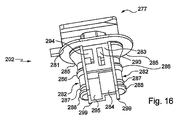
指部202は頭部277を備えている。該頭部の端面の中心部には肉厚部278が設けられており、該肉厚部には、鍵状断面を有する有底状の穴279が形成されている。該端面には、突出する2つの延長部280が設けられている。
The
肉厚部278の下には、長円形状の板状のフランジ部281が延びており、該フランジ部は、指部202が本体203に挿入されたとき、本体203の表面226に当接する。フランジ部281に関して部分278の反対の側から、指部202の残りの部分が延設されている。該部分は、同一形状をした2つの柱状部282を両側に有して概ね長円形に形成されている。柱状部282は、それぞれ矩形プレート部299に配置されている。該矩形プレート部は、フランジ部281に対して直角に同フランジ部281から指部202の先端部に延びている。
An oblong plate-
2つの柱状部282の間の部分は、フランジ部281から延びる第1ステージ部283、および、該第1ステージ部283から延びる第2ステージ部284となっている。
A portion between the two
各柱状部282は、フランジ部281から始まる半切頭円錐形状の外側表面285を有している。該外側表面は、足部203の半切頭円錐部分271の内側表面に略一致する形状を有している。外側表面285には半円筒状表面が連結されており、半円筒状表面は該第1ビード部286まで延在している。先端部へ向けて更に半環状リブ287が設けられており、更に、先端部には第2ビード部288が形成されている。
Each
脚部231は補強部247を有している。該補強部は、ブレース部材233の二つの側面250間の中央に位置している。
The
第1ステージ部283は、正中平面290の両側に設けられた2つの同一な半ステージ部を含む。また2つの柱状部282は、前記正中面に対して鏡像になっている。各半ステージ部は矩形の空所291を有しており、該空所は平面290および第2ステージ部284に隣接する小さな陥凹部292を有している。空所291は2つの開口部293、294によって外部に通じている。開口部293の幅は駆動レバー276の幅と同一となっている。開口部294は開口部293より広いが、ブレース部材233より狭くなっている。これらの高さについては、開口部294の高さが空所291の一般的な高さに相当する一方、開口部293は陥凹部292の近傍に延びて一層高くなっている。第1ステージ部283の1つの面において、1つの半ステージ部の開口部293と、他方の半ステージ部の開口部294とが並んで延在している。
第2ステージ部284は段付き形状の壁295を含み、その返し部が平面290に位置している。前記返し部の両側において、壁295の2つの小壁部分は平面290に対して直角に配置されている。前記返し部の高さはプレート部299の幅より小さくなっており、小壁部分295がプレート部299の全体寸法に対しやや後退して位置するようになっている。
The
図16に示すような角度から指部202を観察すると、壁295の観察側から遠い方の小壁部分が開口部294の下方に位置し、一方で観察側から近い方の小壁部分295は開口部293の下方に位置している。
When the
脚部231は、プレート部299と、壁295の小壁部分の一方と、壁295の2つの小壁部分の間の返し部とによって画成される凹所内に配置される。
The
以下、留め具201の使用方法について述べる。
指部202を本体203に挿入するとき、まずビード部288と第2ステージ部284とを中空部227に入れる。段付き形状の輪郭のために、ブレース部材233には当初抵抗が掛からず、脚部231は退避位置に維持される。押し込むと、ビード部288が半切頭円錐部分の内側表面に接触する。更に押し込むと、タブ273がビード部288の圧力により変形して、前記ビード部が半切頭円錐部分271の下を通過し、その結果、指部202は、脚部231が退避位置にある本体203と係合前位置でスナップ係合する。この位置において、ブレース部材233の端面246は、ステージ部283、284の間の壁から離間している(図18)。
Hereinafter, a method of using the
When inserting the
指部202を更に押し込むと、リブ287が半切頭円錐部分271を押圧してタブ273を変形させ、リブ287がタブ273の下を通過する。同時に、ステージ部283、284の間の壁、より具体的には、該壁の第2ステージ部284に隣接する表面がブレース部材233の表面246に接触し、脚部231を押圧してヒンジ部234を中心に90°揺動させる。
When the
この揺動動作の間、レバー276の端部は、脚部231がヒンジ部234を中心とした揺動動作を阻害しない。と言うのは、このとき、該端部は、開口部293によって形成される空所291に直接進入するからである。
During the swinging operation, the end portion of the
指部202を更に挿入すると、ビード部286が半切頭円錐部分271の内側表面と接触し、ビード部288の場合と同様にスナップ係合する。
When the
この段階で脚部231は伸張位置となる。部分285の外側表面が部分271の内側表面に接触するまで指部202を挿入する。すると、ステージ部283、ステージ部284に隣接するフランジ部281の表面が本体203の端面226と接触する。
At this stage, the
前述した留め具とは対照的に、ここでは指部の端面と端面228とは面一とならない。
また留め具1を取り外すことも可能である。指部202を引くと、指部は前述した挿入方向とは反対の抜き取り方向に駆動される。脚部231は伸張位置にある。
In contrast to the fastener described above, the end face of the finger and the end face 228 are not flush here.
It is also possible to remove the fastener 1. When the
ビード部286およびリブ287は対称な傾斜を有しており、ビード部286およびリブ287は、既述した方向とは反対方向にタブ273の通過を許容するようになっている。脚部231については、駆動レバー276が、空所291の裏側、より具体的には陥凹部292の裏側に到達すると、陥凹部の裏側がレバー276の端部を押し該レバーが揺動し、それに伴い脚部231全体が揺動できるようになっている。この揺動は、ブレース部材233の先端部245が既に第2ステージ部284に隣接して位置しているため可能になる。
The
こうして、脚部231は90°揺動して退避位置に戻ることができる。ブレース部材233の先端部245は壁295の小壁部分の一方に接触し、抜き取り力が作用し続けると、この接触によってこすれが生じる。該こすれによって、脚部231は完全な退避位置に位置できるとともに、退避位置に戻る前の伸張位置における弛緩も除去できる。
Thus, the
一方ビード部288は抜き取り方向への勾配を有していないため、原理上、指部202を本体203から完全に抜き取ることはできず、タブ273がビード部288を止めたままの状態となる。
該留め具はパネルの開口部を通じてパネルに再装着可能である。
On the other hand, since the
The fastener can be reattached to the panel through the panel opening.
図21を参照して上記実施形態の更に他の変形例について述べる。この変形例では、図13〜図20に示した留め具と同様の構成要素に100を加えた参照番号をつけて参照を行う。 Still another modification of the above embodiment will be described with reference to FIG. In this modified example, reference is made by attaching a reference number obtained by adding 100 to the same components as the fasteners shown in FIGS.
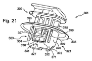
留め具301は指部302を具備する。この指部は、頭部377と、フランジ部381と、空所391および各空所391に対し2つの開口部393、394を設けた第1ステージ部383と、第2ステージ部384と、第1および第2ステージ部383、384の両側の柱状部382とを有する点で指部202と類似している。
The
第2ステージ部384もまた段付き形状となっているが、該変形例では壁395の2つの小壁部分には穴が形成されている。該小壁部分は、返し部を形成する壁と柱状部282との間に設けられた指部302の先端支持部と、矩形開口部内に配置され第1ステージ部へ向けて延設された矩形突出部から成る。柱状部382は、第1ステージ部383に相当する領域内で直線状の半円筒形となっているが、その高さ方向に実質的な全域にわたって三角形断面のくぼみが形成されている。
The
第2ステージ部384では、前記柱状部は、足部382の先端方向に断面が漸減する半切頭円錐形の外側表面を有している。該外側表面には、2つの円形スタッド396が設けられている。これらのスタッド396は柱状部382の外寸を越えてやや突き出ている。そして柱状部382の端部にビード部388が設けられている。
In the
本体303は側壁370を備えている。該側壁は、カラー部335から、支持部330、ヒンジ部334およびフラップ部332を加えた高さより高く延び、ヒンジ部334とフラップ部332とが該側壁の2つの窓の中に位置するようになっている。該窓の両側部には、スタッド396を受容する開口397がある。側壁370端部の断面は縮小され、切欠372が形成されており、本体303の先端部にある切頭円錐部分371を多少変形できるようになっている。
The
上記の変形例によれば、指部302の挿入はスタッド396と開口397によって案内されることになる。更に指部302が行程の終端に達したときのみに、ビード部388が部分371に係合することにより指部302が本体303にスナップ係合する。
According to the above modification, the insertion of the
図23、24を参照して、上記実施形態の更に他の変形例について述べる。これらの図では、同様の構成要素の参照番号には、末尾が同じで図21、22で示した留め具の参照番号に対し100を、また図13〜図20で示した留め具の参照番号に対し200を加えた番号で示されている。 With reference to FIGS. 23 and 24, still another modification of the above embodiment will be described. In these figures, like component reference numbers have the same suffix and are 100 relative to the fastener reference numbers shown in FIGS. 21 and 22, and the fastener reference numbers shown in FIGS. It is shown by the number which added 200 with respect to.
留め具401は、本体403を具備する。該本体は、本体203の全ての部材を有し、更に、内部に脚部431が配置される窓を形成する環状壁470を含む。また壁470は、タブ473が内部に延在する窓も有している。壁470は、先端へ向けて漸次小さくなる。該壁は4つの正方形の切欠部498を含み、これによってスナップ係合する際に必要な柔軟性が付与される。この本体403は本体203に相当するもので、本体303の壁370と同様の壁に沿って支持部が延びている。
The
指部402は、指部302のステージ部383、384と同一の第1および第2ステージ部483、484を含む。柱状部482は柱状部282と同一である。
The
本発明は記述および図示した実施形態に限定されるものではなく、全ての変形例とそれらの実施を網羅するものである。 The invention is not limited to the embodiments described and illustrated, but covers all variants and their implementation.
1 留め具
2 指部
3 本体
10 肩部
20 頭部
21 足部
26 表面
27 中空部
31 脚部
32 フラップ部
33 ブレース部材
34 ヒンジ部
35 カラー部
45 先端部
46 支承面
51 パネル
52 開口部
101 留め具
102 指部
103 本体
120 頭部
121 足部
126 表面
127 中空部
131 脚部
132 フラップ部
133 ブレース部材
134 ヒンジ部
135 カラー部
136 プレート部
138 返し部
145 先端部
146 支承面
151 パネル
152 開口部
160 歯
201 留め具
202 指部
203 本体
221 足部
227 中空部
231 脚部
232 フラップ部
233 ブレース部材
234 ヒンジ部
235 カラー部分
245 先端部
246 支承面
270 環状壁
276 レバー
288 ビード部
292 陥凹部
301 留め具
302 指部
303 本体
327 中空部
331 脚部
332 フラップ部
334 ヒンジ部
335 カラー部
370 環状壁
376 レバー
388 ビード部
392 陥凹部
396 スタッド
397 開口
401 留め具
402 指部
403 本体
427 中空部
431 脚部
432 フラップ部
434 ヒンジ部
435 カラー部
470 環状壁
476 レバー
488 ビード部
492 陥凹部
P 正中面
DESCRIPTION OF SYMBOLS 1
Claims (17)
軸方向中空部(27、127、227、327、427)を有するプラスチック材料製本体(3、103、203、303、403)を具備し、前記本体が、前記開口部(52、152)の周囲を受承するカラー部(35、135、235、335、435)と、前記開口部(52、152)内を通るように構成され、前記本体(3、103、203、303、403)を前記パネル(51、151)に保持するための足部(21、121、221)とを備え、
前記留め具(1、101、201、301、401)は、更に、指部(2、102、202、302、402)を具備しており、該指部を前記中空部(27、127、227、327、427)に挿入して、前記留め具(1、101、201、301、401)が、前記パネル(51、151)に固定される係止位置を取るようになっており、
前記足部(21、121、221)が、2つの脚部(31、131、231、331、431)を具備しており、該脚部が、それぞれブレース部材(33、133、233)を含み、該ブレース部材は同ブレース部材を前記足部(21、121、221)の他の部分に連結するヒンジ部(34、134、234、334、434)の周りを揺動するようになっており、
前記脚部(31、131、231、331、431)の各々の前記ブレース部材(33、133、233)は先端部(45、145、245)を有し、
各脚部(31、131、231、331、431)が、退避位置と、該脚部のフラップ部(32、132、232、332、432)が前記退避位置に対して外側に揺動した伸張位置とを取ることができ、
前記指部(2、102、202、302、402)を前記本体(3、103、203、303、403)に挿入すると、前記脚部(31、131、231、331、431)が前記退避位置から前記伸張位置となり、
前記指部(2、102、202、302、402)が、前記中空部(27、127、227、327、427)に挿入され前記係止位置となったとき、各ブレース部材(33、133、233)の前記先端部(45、145、245)が前記指部に接し、これにより前記脚部(31、131、231、331、431)の各々が前記伸張位置に保持されるようにした留め具において、
該脚部の各々がフラップ部(32、132、232、332、432)を具備し、各脚部(31、131、231、331、431)は、フラップ部(32、132、232、332、432)が、他方の脚部(31、131、231、331、431)のフラップ部(32、132、232、332、432)と向い合い、該脚部のブレース部材(33、133、233)が、該の脚部のヒンジ部(34、134、234、334、434)の方向と、前記他方の脚部(31、131、231、331、431)の方向とに配向され、該脚部のブレース部材(33、133、233)が前記フラップ部(32、132、232、332、432)間において、他方の脚部(31、131、231、331、431)のブレース部材(33、133、233)に対して重なり合った退避位置を取ることができ、
前記フラップは(32、132、232、332、432)外側表面(40)が凸状に形成されており、前記伸張位置においてパネル(51)の表面(54)に接触するようになっており、
前記脚部(231、331、431)のそれぞれを前記伸張位置から前記退避位置に駆動するレバー(276、376、476)を更に含み、前記レバー(276、376、476)が前記フラップ部(232、332、432)の切欠部(275、375、475)内に延び、前記ヒンジ部(234、334、434)の一部から出ており、前記レバー(276、376、476)が前記フラップ部(232、332、432)の平面内を前記ヒンジ部(234、334、434)と直角かつこれを越えるように延設されていることを特徴とした留め具。 A fastener for performing blind mounting on a panel (51, 151) provided with openings (52, 152),
A plastic material body (3, 103, 203, 303, 403) having an axial hollow portion (27, 127, 227, 327, 427), the body surrounding the opening (52, 152) The collar portion (35, 135, 235, 335, 435) for receiving the body and the opening (52, 152) are configured to pass through the main body (3, 103, 203, 303, 403). Feet (21, 121, 221) for holding on the panels (51, 151),
The fastener (1, 101, 201, 301, 401) further includes a finger portion (2, 102, 202, 302, 402), and the finger portion is connected to the hollow portion (27, 127, 227). , 427, 427), and the fasteners (1, 101, 201, 301, 401) take a locking position to be fixed to the panels (51, 151),
The feet (21, 121, 221) include two legs (31, 131, 231, 331, 431), and the legs include brace members (33, 133, 233), respectively. The brace member swings around a hinge part (34, 134, 234, 334, 434) that connects the brace member to the other part of the foot part (21, 121, 221). ,
Each of the brace members (33, 133, 233) of the legs (31, 131, 231, 331, 431) has a tip (45, 145, 245),
Each leg (31, 131, 231, 331, 431) is in the retracted position and the flap part (32, 132, 232, 332, 432) of the leg is swung outward with respect to the retracted position. Can take position and
When the fingers (2, 102, 202, 302, 402) are inserted into the main body (3, 103, 203, 303, 403), the legs (31, 131, 231, 331, 431) are moved to the retracted position. To the extension position,
When the finger portions (2, 102, 202, 302, 402) are inserted into the hollow portions (27, 127, 227, 327, 427) and become the locking positions, the brace members (33, 133, 233) the tip (45, 145, 245) is in contact with the finger portion, so that each of the legs (31, 131, 231, 331, 431) is held in the extended position. In the ingredients
Each of the legs includes a flap portion (32, 132, 232, 332, 432), and each leg portion (31, 131, 231, 331, 431) includes a flap portion (32, 132, 232, 332, 432) faces the flap portion (32, 132, 232, 332, 432) of the other leg portion (31, 131, 231, 331, 431), and the brace member (33, 133, 233) of the leg portion. Are oriented in the direction of the hinge portion (34, 134, 234, 334, 434) of the leg and the direction of the other leg (31, 131, 231, 331, 431), The brace members (33, 133, 233) of the other leg portions (31, 131, 231, 331, 431) are disposed between the flap portions (32, 132, 232, 332, 432). It is possible to take the overlapping retracted position with respect to the 33 and 233),
The flap (32, 132, 232, 332, 432) has a convex outer surface (40) that contacts the surface (54) of the panel (51) in the extended position;
Each of the leg portions (231, 331, 431) further includes a lever (276, 376, 476) for driving each of the leg portions (231, 331, 431) from the extended position to the retracted position. 332, 432) extending into the notches (275, 375, 475) of the hinges (234, 334, 434), and the levers (276, 376, 476) are connected to the flaps. A fastener characterized by extending in a plane of (232, 332, 432) so as to be perpendicular to and beyond the hinge portion (234, 334, 434) .
Applications Claiming Priority (3)
| Application Number | Priority Date | Filing Date | Title |
|---|---|---|---|
| FR0653210 | 2006-07-31 | ||
| FR0653210A FR2904386B1 (en) | 2006-07-31 | 2006-07-31 | ATTACHE TO BE MOUNTED IN THE BLIND |
| PCT/IB2007/001730 WO2008015511A1 (en) | 2006-07-31 | 2007-06-25 | Fastener for blind mounting |
Publications (3)
| Publication Number | Publication Date |
|---|---|
| JP2009545711A JP2009545711A (en) | 2009-12-24 |
| JP2009545711A5 JP2009545711A5 (en) | 2010-08-12 |
| JP5324443B2 true JP5324443B2 (en) | 2013-10-23 |
Family
ID=37762642
Family Applications (1)
| Application Number | Title | Priority Date | Filing Date |
|---|---|---|---|
| JP2009522349A Expired - Fee Related JP5324443B2 (en) | 2006-07-31 | 2007-06-25 | Blind mount fastener |
Country Status (6)
| Country | Link |
|---|---|
| EP (1) | EP2047126B1 (en) |
| JP (1) | JP5324443B2 (en) |
| CN (1) | CN101460748B (en) |
| DE (1) | DE602007008250D1 (en) |
| FR (1) | FR2904386B1 (en) |
| WO (1) | WO2008015511A1 (en) |
Families Citing this family (8)
| Publication number | Priority date | Publication date | Assignee | Title |
|---|---|---|---|---|
| JP5214310B2 (en) * | 2008-04-15 | 2013-06-19 | トヨタ車体株式会社 | Deck side trim mounting structure |
| DE102009014678A1 (en) | 2009-03-25 | 2010-09-30 | A.Raymond Et Cie | Spreizniet |
| IT1397287B1 (en) * | 2009-12-01 | 2013-01-04 | Illinois Tool Works | SELF-LOCKING ACCESSORY FOR A VEHICLE BODY PART. |
| JP5648756B2 (en) * | 2012-07-30 | 2015-01-07 | トヨタ自動車株式会社 | Fixture, fixture removal structure, and curtain airbag fixing device |
| FR3020099B1 (en) * | 2014-04-16 | 2017-08-18 | Illinois Tool Works | CLAMP FOR ATTACHING A PANEL TO A SUPPORT, METHOD FOR CARRYING OUT THE SAME, AND AUTOMOTIVE EQUIPMENT |
| ES2688107B2 (en) * | 2017-04-28 | 2019-07-10 | A Raymond Et Cie | FIXING FOR ASSEMBLY ON A SUPPORT |
| CN109764315A (en) * | 2019-03-15 | 2019-05-17 | 豪尔赛科技集团股份有限公司 | A kind of fixation device and lamp installation method for small space lamp installation |
| FR3121484A1 (en) * | 2021-03-31 | 2022-10-07 | Illinois Tool Works | FASTENING SET FOR DETACHABLE ASSEMBLY OF A PANEL TO A STRUCTURE |
Family Cites Families (9)
| Publication number | Priority date | Publication date | Assignee | Title |
|---|---|---|---|---|
| US3188905A (en) * | 1962-04-03 | 1965-06-15 | David I Millet | Fastening device with pivotal locking means |
| JPS5335509B2 (en) * | 1972-07-26 | 1978-09-27 | ||
| JPS58151708U (en) * | 1982-04-07 | 1983-10-11 | 株式会社ニフコ | Fastener |
| JPS6087741U (en) * | 1983-11-19 | 1985-06-17 | 加藤発条株式会社 | Glove box opening restriction stopper |
| JPH0422088Y2 (en) * | 1987-08-07 | 1992-05-20 | ||
| FR2805503B1 (en) * | 2000-02-28 | 2002-05-31 | Itw De France | SHUTTER FOR AN OPENING MADE IN A SHEET |
| JP2004316856A (en) * | 2003-04-18 | 2004-11-11 | Piolax Inc | Clip and its manufacturing method |
| JP2005351462A (en) * | 2004-06-14 | 2005-12-22 | Nifco Inc | Clip |
| FR2873771B1 (en) * | 2004-07-30 | 2008-08-15 | I T W De France Sas | FEMALE FITTING AND SHUTTER COMPRISING THE SAME |
-
2006
- 2006-07-31 FR FR0653210A patent/FR2904386B1/en not_active Expired - Fee Related
-
2007
- 2007-06-25 CN CN200780020388XA patent/CN101460748B/en not_active Expired - Fee Related
- 2007-06-25 JP JP2009522349A patent/JP5324443B2/en not_active Expired - Fee Related
- 2007-06-25 WO PCT/IB2007/001730 patent/WO2008015511A1/en active Application Filing
- 2007-06-25 DE DE602007008250T patent/DE602007008250D1/en active Active
- 2007-06-25 EP EP07789442A patent/EP2047126B1/en active Active
Also Published As
| Publication number | Publication date |
|---|---|
| FR2904386B1 (en) | 2008-10-17 |
| JP2009545711A (en) | 2009-12-24 |
| DE602007008250D1 (en) | 2010-09-16 |
| WO2008015511A1 (en) | 2008-02-07 |
| FR2904386A1 (en) | 2008-02-01 |
| CN101460748A (en) | 2009-06-17 |
| EP2047126A1 (en) | 2009-04-15 |
| EP2047126B1 (en) | 2010-08-04 |
| CN101460748B (en) | 2011-01-19 |
Similar Documents
| Publication | Publication Date | Title |
|---|---|---|
| JP5324443B2 (en) | Blind mount fastener | |
| US6955514B2 (en) | Connector with male part for final fixing | |
| JP4535892B2 (en) | clip | |
| JP4943415B2 (en) | Stop | |
| EP2090475B1 (en) | Two stage high retention fastener | |
| JP5118066B2 (en) | Fastener with snap-type engagement part that pushes into hole in panel | |
| WO2012002339A1 (en) | Grommet | |
| JP2002213417A (en) | Clasp | |
| JPH0923909A (en) | Cord fastener | |
| JP2006046537A (en) | Fastener | |
| KR101154685B1 (en) | Fastener | |
| EP2204589A1 (en) | Clip | |
| KR101172181B1 (en) | Clip | |
| JP2007071368A (en) | Clip | |
| CN106050855B (en) | Fixing piece | |
| JP2003247518A (en) | Integrally molded clip and molding method thereof | |
| JP2010144830A (en) | Fastener | |
| JP2006242286A (en) | Clip | |
| JP2017096449A (en) | clip | |
| JP2005047225A (en) | Insert retaining structure of mold, foam molding method, clip for fitting ea material and ea material | |
| CN107407109B (en) | Handle for operation and handle main body structure of handle for operation | |
| JP4827895B2 (en) | clip | |
| JP2011105045A (en) | Spoiler | |
| JP2010196890A (en) | Assembling structure of clip and mounting member | |
| JP2011073457A (en) | Impact energy absorber-mounting clip holding structure for impact energy absorber molding die, and impact energy absorber-mounting clip |
Legal Events
| Date | Code | Title | Description |
|---|---|---|---|
| A521 | Request for written amendment filed |
Free format text: JAPANESE INTERMEDIATE CODE: A523 Effective date: 20100625 |
|
| A621 | Written request for application examination |
Free format text: JAPANESE INTERMEDIATE CODE: A621 Effective date: 20100625 |
|
| A521 | Request for written amendment filed |
Free format text: JAPANESE INTERMEDIATE CODE: A523 Effective date: 20110824 |
|
| A131 | Notification of reasons for refusal |
Free format text: JAPANESE INTERMEDIATE CODE: A131 Effective date: 20120626 |
|
| A977 | Report on retrieval |
Free format text: JAPANESE INTERMEDIATE CODE: A971007 Effective date: 20120629 |
|
| A521 | Request for written amendment filed |
Free format text: JAPANESE INTERMEDIATE CODE: A523 Effective date: 20120824 |
|
| A131 | Notification of reasons for refusal |
Free format text: JAPANESE INTERMEDIATE CODE: A131 Effective date: 20130226 |
|
| A521 | Request for written amendment filed |
Free format text: JAPANESE INTERMEDIATE CODE: A523 Effective date: 20130527 |
|
| TRDD | Decision of grant or rejection written | ||
| A01 | Written decision to grant a patent or to grant a registration (utility model) |
Free format text: JAPANESE INTERMEDIATE CODE: A01 Effective date: 20130618 |
|
| A61 | First payment of annual fees (during grant procedure) |
Free format text: JAPANESE INTERMEDIATE CODE: A61 Effective date: 20130718 |
|
| R150 | Certificate of patent or registration of utility model |
Free format text: JAPANESE INTERMEDIATE CODE: R150 |
|
| R250 | Receipt of annual fees |
Free format text: JAPANESE INTERMEDIATE CODE: R250 |
|
| R250 | Receipt of annual fees |
Free format text: JAPANESE INTERMEDIATE CODE: R250 |
|
| LAPS | Cancellation because of no payment of annual fees |