JP5320135B2 - Boiled noodle machine - Google Patents
Boiled noodle machine Download PDFInfo
- Publication number
- JP5320135B2 JP5320135B2 JP2009092590A JP2009092590A JP5320135B2 JP 5320135 B2 JP5320135 B2 JP 5320135B2 JP 2009092590 A JP2009092590 A JP 2009092590A JP 2009092590 A JP2009092590 A JP 2009092590A JP 5320135 B2 JP5320135 B2 JP 5320135B2
- Authority
- JP
- Japan
- Prior art keywords
- hot water
- tank
- storage tank
- preheating
- plate
- Prior art date
- Legal status (The legal status is an assumption and is not a legal conclusion. Google has not performed a legal analysis and makes no representation as to the accuracy of the status listed.)
- Active
Links
Images


Description
本発明は、レストランや食堂等において、そばやうどん、ラーメン、スパゲッティ等の麺をゆでるゆで麺機に関する。特には、差し水(湯)に伴う貯湯槽の局部的な温度低下の問題を改善したゆで麺機に関する。 The present invention relates to a boiled noodle machine that boiles noodles such as buckwheat noodles, noodles, ramen, spaghetti and the like in a restaurant or a restaurant. In particular, the present invention relates to a boiled noodle machine that has improved the problem of local temperature drop in a hot water tank caused by hot water.
ゆで麺機は、そばやうどん、ラーメン、スパゲッティ等のメニューを提供するレストランや食堂等の厨房に設置されている。ゆで麺機には、複数の麺カゴ(テボ)を浸すことができる貯湯槽や、この貯湯槽内の湯を沸騰させるガスバーナや電気ヒーター等の熱源等が備えられている。麺カゴ内に入れられた麺は、貯湯槽内の湯の沸騰力によって攪拌されながらゆでられる。ここで、沸騰力とは、水の沸騰時に泡がたくさん発生した水流の勢いのことであり、麺が塊にならないように攪拌しながらゆでる作用を有する。 Boiled noodle machines are installed in restaurants and restaurants such as soba, udon, ramen and spaghetti. The boiled noodle machine is equipped with a hot water storage tank in which a plurality of noodle baskets (tebo) can be immersed, a heat source such as a gas burner or an electric heater for boiling the hot water in the hot water storage tank. The noodles put in the noodle basket are boiled while being stirred by the boiling power of the hot water in the hot water tank. Here, the boiling power is the momentum of the water flow in which a lot of bubbles are generated when the water is boiled, and has a function of boiling while stirring so that the noodles do not become lumps.
ところで、そばやうどん等の麺には、ゆでる前の時点で打ち粉等がまぶされている。このような麺を貯湯槽内でゆでると、打ち粉等がゆで湯に溶け落ちるため、麺のゆで数が多くなるに連れてゆで湯が段々と白濁したり、ぬめりが生じてくる。このようなゆで湯で麺をゆでると、ゆであがった麺のおいしさが劣化するおそれがある。そのため、ゆで湯の汚れを緩和して濁りやぬめりのない状態に保つために、麺をゆでている間以外にも常に貯湯槽内に給水(差し水)を行う必要がある。 By the way, noodles such as soba and udon are dusted with dust before being boiled. When such noodles are boiled in a hot water storage tank, the dusting powder dissolves in the boiled hot water, and as the number of boiled noodles increases, the boiled hot water gradually becomes cloudy or becomes slimy. When the noodles are boiled with such boiled water, the taste of the boiled noodles may be deteriorated. Therefore, in order to alleviate the dirt of the boiled hot water and keep it free of turbidity and sliminess, it is necessary to always supply water (pour water) into the hot water storage tank other than while the noodles are being boiled.
差し水は、給水や給湯器から供給される場合が多い。しかしながら、いずれの場合も、差し水温度は100℃以下であり、このような低温の差し水を供給すると、貯湯槽内のお湯の温度が部分的に低下する。そこで、差し水の温度を予め一定程度加温し、これを供給することが考えられる。このような観点から、差し水の加温機能を備えたゆで麺機が提案されている(例えば、特許文献1、特許文献2参照)。 The feed water is often supplied from a water supply or a water heater. However, in any case, the feed water temperature is 100 ° C. or less, and when such a low temperature feed water is supplied, the temperature of the hot water in the hot water storage tank partially decreases. Therefore, it is conceivable to heat the feed water to a certain degree in advance and supply it. From such a point of view, a boiled noodle machine having a function of heating water is proposed (see, for example, Patent Document 1 and Patent Document 2).
特許文献1に開示されたゆで麺機は、貯水槽内に、ゆで釜(貯湯槽)を熱した際に生じる煙や熱が排出される排煙筒を設置し、貯水槽内の水を熱してゆで釜に供給する。このゆで麺機は、ゆで釜を熱した際の煙や熱を有効利用することはできるが、排煙筒が機体本体内及び貯水槽の内部を通るため、構造が複雑であり、清掃等のメンテナンスもしがたい等の欠点がある。また、この種の排気熱を利用する方式のものは、排煙ガスの発生するガス加温式のものでのみ有効であり、電気加温式のもの等には適用できないので、汎用性に乏しいという欠点もある。 The boiled noodle machine disclosed in Patent Document 1 is provided with a smoke exhaust pipe that discharges smoke and heat generated when a boiled kettle (hot water storage tank) is heated in the water storage tank, and heats the water in the water storage tank. Supply to boiled kettle. This boiled noodle machine can effectively use the smoke and heat generated when the boiled kettle is heated, but the structure is complex because the smoke evacuation tube passes through the inside of the main body and the water storage tank, and maintenance such as cleaning There are some drawbacks. In addition, this type of exhaust heat system is effective only for the gas heating type that generates flue gas, and is not applicable to the electric heating type, etc. There is also a drawback.
特許文献2に開示された麺類の製造装置は、排湯の熱を有効利用して差し水を加温するものである。そのため、差し水を加温するための電気設備は不要であり、構造も簡単である等の利点が挙げられている。しかしながら、熱交換器には排湯パイプ、冷水パイプ、差し水パイプが繋がる構造であるため、配管が複雑化することは否めない。
The apparatus for producing noodles disclosed in
本発明は上記の問題点に鑑みてなされたものであって、比較的簡単な構造であるとともに、容易に着脱できる予熱タンクを備え、貯湯槽内の局部的な温度低下を招くことなく高温の差し湯を供給できるゆで麺機を提供することを目的とする。 The present invention has been made in view of the above-described problems, and has a relatively simple structure and includes a preheating tank that can be easily attached and detached, and has a high temperature without causing a local temperature drop in the hot water tank. An object is to provide a boiled noodle machine capable of supplying hot water.
本発明のベースとなるゆで麺機は、 麺をゆでる熱湯を貯める貯湯槽と、 該貯湯槽内の湯を加熱する熱源と、 を備えるゆで麺機であって、 さらに、前記貯湯槽に供給する差し水又は差し湯を予熱する、前記貯湯槽に浸漬される予熱タンクを具備する。 A boiled noodle machine as a base of the present invention is a boiled noodle machine comprising: a hot water storage tank for storing hot water for boiling noodles; and a heat source for heating the hot water in the hot water storage tank, and further supplying the hot water storage tank to the hot water storage tank preheating the insert water or pointing water, it includes a preheating tank to be immersed in the hot water storage tank.
本発明によれば、貯湯槽に予熱タンクを浸漬することにより、予熱タンク内の水(お湯)が貯湯槽内の高温のお湯と熱交換し、加温される。そして、この予熱タンク内の加温されたお湯を、差し湯として貯湯槽に供給することにより、比較的高い温度の差し湯を供給できる。なお、予熱タンク周辺の貯湯槽内の湯温は、予熱タンク内の水を間接加熱する分低下するが、差し水を貯水槽の特定箇所に入れる(落とす)よりも貯水槽内の温度分布を乱す弊害は少ない。 According to the present invention, by immersing the preheating tank in the hot water storage tank, the water (hot water) in the preheating tank exchanges heat with the hot water in the hot water storage tank and is heated. And the hot water in this preheating tank can be supplied to a hot water storage tank as hot water, and a hot water of comparatively high temperature can be supplied. The hot water temperature in the hot water tank around the preheating tank is reduced by indirectly heating the water in the preheating tank, but the temperature distribution in the hot water tank is less than that in the specific place of the water tank. There are few harmful effects.
本発明においては、 前記予熱タンクが、前記貯湯槽内の奥側(調理者対面位置の反対側)に浸漬されることが好ましい。 In this invention, it is preferable that the said preheating tank is immersed in the back | inner side (opposite side of a chef facing position) in the said hot water storage tank.
ゆで麺機は通常複数の麺カゴをセットできる構造であるが、調理者に最も近く調理者が扱いやすい、貯湯槽の手前側が多用されるのが一般的である。ただし、昼食のピーク時など一度に多人数分の麺をゆでる必要がある場合は、奥側にも面の入った麺カゴがセットされることもある。前述のように、予熱タンク内の水(お湯)は、貯湯槽内の沸騰水と熱交換して加温されるので、特に熱源の出力が絞られている場合などは、貯湯槽内の予熱タンク周囲のお湯の温度が下がることが懸念される。そこで、予熱タンクを、普段使われる頻度が高い手前側の部分から離れた奥側に設置することにより、頻繁に麺カゴがセットされる、貯湯槽の手前側の部分の沸騰力を損ねないようにできる。 A boiled noodle machine usually has a structure in which a plurality of noodle baskets can be set. However, it is common to use the front side of the hot water tank that is closest to the cooker and easy for the cooker to handle. However, if it is necessary to boil noodles for a large number of people at one time, such as at the peak of lunch, a noodle basket with a surface may be set on the back side. As described above, the water (hot water) in the preheating tank is heated by exchanging heat with the boiling water in the hot water tank, so that the preheating in the hot water tank is particularly difficult when the output of the heat source is limited. There is concern that the temperature of hot water around the tank will drop. Therefore, by installing a preheating tank on the far side away from the part on the near side that is frequently used, the boiling power of the part on the near side of the hot water tank where the noodle basket is frequently set is not impaired. Can be.
本発明においては、 前記予熱タンクに供給された差し水又は差し湯は、該タンク内でいったん下方に向かい、その後上昇するように流れた後、前記貯湯槽に供給されることが好ましい。 In the present invention, it is preferable that the water or hot water supplied to the preheating tank flows downward in the tank and then flows upward and then supplied to the hot water storage tank.
本発明によれば、予熱タンクに供給された水(お湯)が同タンク内の比較的長い経路を通った後で貯湯槽に供給される。このため、予熱タンク内の水(お湯)をこの経路中で十分に昇温できる。 According to the present invention, water (hot water) supplied to the preheating tank is supplied to the hot water storage tank after passing through a relatively long path in the tank. For this reason, water (hot water) in the preheating tank can be sufficiently heated in this path.
本発明においては、 前記予熱タンクの上縁部の両端に切り欠き又は凸部が形成されており、 前記貯湯槽の上部の奥部に、前記切り欠き又は凸部が係合する凸部又は切り欠きが形成されており、 前記切り欠きを前記凸部に係合させることにより、前記予熱タンクが前記貯湯槽に、着脱容易かつ浮き上がらないように取り付けられることが好ましい。 In the present invention, notches or protrusions are formed at both ends of the upper edge of the preheating tank, and the protrusions or notches that engage with the notches or protrusions in the upper part of the hot water storage tank. It is preferable that a notch is formed, and the preheating tank is attached to the hot water tank so as not to be easily detached and lifted by engaging the notch with the convex portion.
本発明のゆで麺機は、さらに、前記貯湯槽の底板上に設置される沸騰強化板を備えることもできる。この場合、 該沸騰強化板が、 前記底板からある寸法を隔てて該底板を覆うように広がり、麺カゴの下方近傍に開口が形成された平板と、 該平板の下面から下方に延びる、該平板と前記貯湯槽の底板間の空間を複数の区画に仕切る仕切り板と、を有し、 前記仕切り板が、前記予熱タンクに近い位置に優先的に沸騰水を噴出するように配置されていることが好ましい。 The boiled noodle machine according to the present invention may further include a boil strengthening plate installed on the bottom plate of the hot water storage tank. In this case, the boiling strengthening plate spreads so as to cover the bottom plate with a certain distance from the bottom plate, and a flat plate in which an opening is formed near the lower portion of the noodle basket, and the flat plate extending downward from the lower surface of the flat plate And a partition plate that partitions a space between the bottom plate of the hot water storage tank into a plurality of compartments, and the partition plate is disposed so as to eject boiling water preferentially at a position close to the preheating tank. Is preferred.
熱源が貯湯槽の下方に設置されている場合、貯湯槽の底板の上方に沸騰強化板を設けると、同板と貯湯槽の底板との間の空間が集中的に熱源により加熱されて沸騰する。そして、この沸騰したお湯を開口から麺カゴに向けて集中的に噴出することにより、麺カゴ内の麺をゆでるとともに撹拌する力(沸騰力)が得られる。そして、沸騰強化板と底板間の空間を、仕切り板で区画し、各区画の面積を調整することにより、各区画の入熱を調整できる。例えば、区画の面積を広くすると、熱源に接する面積が広くなり、強い沸騰力が得られる。そこで、前述のように、予熱タンクを設置することによる貯湯槽内のお湯の温度の低下を補うために、予熱タンクが設置される貯湯槽の奥側の区画の面積を広くすれば、貯湯槽の奥側の部分に優先的に沸騰水を配分できる。 When the heat source is installed below the hot water tank, if a boiling strengthening plate is provided above the bottom plate of the hot water tank, the space between the plate and the bottom plate of the hot water tank is intensively heated by the heat source and boils. . Then, the boiling hot water is intensively ejected from the opening toward the noodle basket, so that the noodles in the noodle basket are boiled and stirred (boiling force) is obtained. And the heat input of each division can be adjusted by dividing the space between a boiling reinforcement board and a bottom board with a partition plate, and adjusting the area of each division. For example, when the area of the compartment is increased, the area in contact with the heat source is increased, and a strong boiling force is obtained. Therefore, as described above, in order to compensate for the decrease in the temperature of hot water in the hot water tank due to the installation of the preheating tank, if the area of the compartment on the back side of the hot water tank where the preheating tank is installed is widened, Boiling water can be distributed preferentially to the back side of the.
本発明のゆで麺機は、さらに、前記貯湯槽の上側に配置された、麺カゴを受けるカゴ受け板を備えることもできる。この場合、 前記カゴ受け板が、 前記貯湯槽内の湯面上を覆い、湯熱により加温される覆板部と、 該覆板部の複数箇所に分散して形成された、前記麺カゴを前記貯湯槽に入れて置くためのカゴ置き開口部と、 前記覆板部に形成された、該覆板部の上面を流して昇温した湯(差し湯)を前記貯湯槽内へと導く供給口部と、を有し、 前記予熱タンクから、前記カゴ受け板の覆板部上に差し湯を供給することが好ましい。 The boiled noodle machine of the present invention may further include a basket receiving plate that is disposed on the upper side of the hot water storage tank and receives the noodle basket. In this case, the basket receiving plate covers the surface of the hot water in the hot water tank and is heated by hot water, and the noodle basket formed in a dispersed manner at a plurality of locations of the cover plate portion. A basket holding opening for placing the hot water in the hot water storage tank, and hot water (pour hot water) formed in the cover plate part and flowing through the upper surface of the cover plate part to guide the hot water into the hot water storage tank It is preferable that hot water is supplied from the preheating tank onto the cover plate portion of the basket receiving plate.
カゴ受け板を備えることにより、貯湯槽の湯面と同板との間の空間に貯湯槽内のお湯から発生する熱が留まって大気中に逃げないので、貯湯槽内のお湯の温度の保温効果が得られる。また、カゴ受け板の覆板は、貯湯槽内のお湯によって加温されている。この覆板上に予熱タンクから差し湯を供給すると、差し湯は覆板上を流れて供給口部に達する間に、覆板と熱交換し、さらに加温される。したがって、より高温の差し湯を貯湯槽内に供給することができる。 By providing the basket support plate, the heat generated from the hot water in the hot water tank stays in the space between the hot water surface of the hot water tank and the same plate and does not escape to the atmosphere, so the temperature of the hot water in the hot water tank is kept warm. An effect is obtained. Further, the cover plate of the basket receiving plate is heated by hot water in the hot water storage tank. When hot water is supplied from the preheating tank onto the cover plate, the hot water exchanges heat with the cover plate and further heats while it flows on the cover plate and reaches the supply port. Therefore, hotter hot water can be supplied into the hot water tank.
本発明においては、 前記熱源が2個の誘導加熱コイルを前記貯湯槽の前後方向に並列したものであり、 該コイルの各々の巻き方向が反対方向であり、前記両コイルが接する部分では、前記両コイルを流れる電流の向きが同じ方向であることが好ましい。 In the present invention, the heat source has two induction heating coils arranged in parallel in the front-rear direction of the hot water tank, the winding direction of each of the coils is opposite, and in the part where both the coils are in contact, It is preferable that the direction of the current flowing through both coils is the same.
熱源として誘導加熱コイルを使用することにより、ガスを用いた場合ほど、厨房内の温度の上昇や、厨房内の空気が汚れるなどの環境を悪化を招かないので、調理環境を改善できる。さらに、誘導加熱コイルを並列し、両コイルが接する部分でコイルに流れる電流の向きを同じ方向とすると、同部で発生する磁力線によって誘起されるうず電流の密度が高くなるので、発生する熱量が多くなる。つまり、貯湯槽の前後方向における中央付近の加熱力が高くなる。そして、前述の沸騰強化板のような、貯湯槽の奥側の部分に優先的に沸騰水を配分できるような手段を使用することにより、中央付近の沸騰水を奥側に配分できる。 By using an induction heating coil as a heat source, the cooking environment can be improved because the temperature rise in the kitchen and the environment in which the air in the kitchen becomes dirty are not deteriorated as the gas is used. Furthermore, if the induction heating coils are arranged in parallel and the direction of the current flowing through the coil is the same at the part where both coils are in contact, the density of the eddy current induced by the magnetic field lines generated at the same part increases, so the amount of generated heat is reduced. Become more. That is, the heating power near the center in the front-rear direction of the hot water tank is increased. And the boiling water near the center can be distributed to the back side by using means such as the above-described boiling strengthening plate that can distribute the boiling water preferentially to the back side of the hot water tank.
以上の説明から明らかなように、本発明によれば、貯湯槽に予熱タンクを浸漬しているので、予熱タンク内の水(お湯)が貯湯槽内の高温のお湯と熱交換して加温される。そして、この予熱タンク内の加温されたお湯を、差し水として貯湯槽に供給することにより、比較的高い温度の差し水を供給できる。なお、予熱タンクは貯湯槽の奥側に設置した場合には、使用頻度の高い貯湯槽の手前側の部分の沸騰力を損ねない。さらに、工夫した沸騰強化板を設けることもでき、その場合には、予熱タンク内のお湯と熱交換したことによる貯湯槽内のお湯の温度低下を緩和することができる。 As is clear from the above description, according to the present invention, since the preheating tank is immersed in the hot water tank, the water (hot water) in the preheating tank exchanges heat with the hot water in the hot water tank for heating. Is done. And the hot water in this preheating tank can be supplied to a hot water storage tank as hot water, so that hot water of relatively high temperature can be supplied. In addition, when a preheating tank is installed in the back | inner side of a hot water tank, it does not impair the boiling power of the part of the near side of the hot water tank which is used frequently. Furthermore, a special boiling strengthening plate can be provided. In that case, the temperature drop of the hot water in the hot water storage tank due to heat exchange with the hot water in the preheating tank can be mitigated.
以下、本発明の実施の形態について、図面を参照しながら詳細に説明する。
まず、図1を参照してゆで麺機全体の構成を説明する。
ゆで麺機1は、四角い箱状の本体2を備えている。この本体2の内部の上方には、四角形状の貯湯槽10が配置されており、下方には熱源20が配置されている。この例では、貯湯槽10に麺カゴ3を縦方向(奥行き方向、前後方向)に2列、横方向(左右方向)に3列収容する貯湯槽について説明する。さらに、貯湯槽10内には、予熱タンク30及び沸騰強化板50が脱着可能に取り付けられている(詳細後述)。
Hereinafter, embodiments of the present invention will be described in detail with reference to the drawings.
First, the configuration of the entire boiled noodle machine will be described with reference to FIG.
The boiled noodle machine 1 includes a square box-shaped
本体2の背部の中央には、水源(図示されず)に繋がる差し水パイプ4が設けられている。この差し水パイプ4の吐出口は、貯湯槽10内に向けて垂下している。本体2の前縁には、貯湯槽からあふれたお湯を排出するオーバーフロー排水口5が設けられている。この排水口5はオーバーフロー排出管6に接続しており、貯湯槽10からあふれたお湯が排出される。
貯湯槽10には、主給水管(図示されず)が接続しており、同槽内に水を供給する。主給水管は、本体2の前面に設けられた給水コック7で開閉される。また、貯湯槽10の底板には、排水口11が設けられている。この排水口11は排水管12に接続している。
In the center of the back portion of the
A main water supply pipe (not shown) is connected to the
熱源20としては、2個の誘導加熱コイル21、22を貯湯槽10の前後方向に並列したものが使用できる。コイル21、22の巻き方向は反対方向であり、両コイルが接する部分では、両コイルを流れる電流の向きが同じ方向となっている。このように、両コイルが接する部分でコイルに流れる電流の向きを同じ方向とすると、同部で発生する磁力線によって誘起されるうず電流の密度が高くなるので、発生する熱量が多くなる。つまり、貯湯槽10の前後方向における中央付近の加熱力が高くなる。
As the
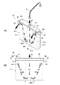
次に、図2を参照して予熱タンク30について説明する。
予熱タンク30は、薄い直方体状の中空の本体31と、蓋41とを有する。本体31は、前後板31a、31bと、左右の側板31c、31d、及び、底板31eを有し、上面が開口している。本体31の高さは貯湯槽10の深さとほぼ等しく、幅は貯湯槽10の幅とほぼ等しい。奥行きは、貯湯槽10内にセットされる最も奥側の麺カゴと、ゆで麺機本体2の背部との間のスペースに収容可能な長さである。本体31の上面の開口は蓋41で開閉される。
Next, the preheating
The preheating
蓋41のほぼ中央には開口42が開けられて、差し水パイプ4の吐出口から滴下する差し水がこの開口から本体31内へ入る。本体31内の、開口42の両側には、本体内部を縦方向に仕切るように延びる左右ガイド板32、33が設けられている。左右ガイド板32、33の下端は本体31の底板31eには達しておらず、図2(B)に示すように、ガイド板32、33の下端と本体31の底板31eとの間にはスキマCが開いている。ここで、両側が左右ガイド板32、33で区切られた区画を中央区画S1と呼び、その左右の区画を各々左区画S2、右区画S3と呼ぶ。
また、本体31の前板31aの両上隅には、開口35が開けられており、これらの開口35には前方(手前方向)に延びるとい36が設けられている。
An
In addition,
さらに、予熱タンク30の本体31の両側板31c、31dの上端付近には、横方向に張り出す係合片37が取り付けられている。各係合片37には、奥側の端面から手前側に延びるU字型のスリット38が形成されている。
一方、図3に示すように、貯湯槽10の両側板の上面の奥側端部付近には、ヘッド14付きの凸部15が立設されている。これらの凸部15に、予熱タンク30の各係止片37のスリット38を係合させることにより、予熱タンク30が貯湯槽10に取り付けられる。取り付ける際は、図3に示すように、予熱タンク30を貯湯槽10に入れて、各係止片37を凸部15のやや手前に置く。そして、そのまま予熱タンク30を奥方向にスライドさせれば、やがて、各凸部15が各々タンク30の係止片37のスリット38に係合する。そして、予熱タンク30の係合片37が凸部15のヘッド14で押さえられるので、予熱タンク30を貯湯槽10内で浮き上がらないように保持できる。
Further, an
On the other hand, as shown in FIG. 3, a
図2を参照して、予熱タンク30による差し水加温方法について説明する。
差し水パイプ4から予熱タンク30の蓋41の開口42を通って差し水(一例で65℃)が本体31に供給されると、この差し水は左右ガイド板32、33で区切られた中央区画S1内を降下する。その後、左右ガイド板32、33の下端と本体31の底板31eとの間のスキマCから、その両側の左右区画S2、S3に流れる。そして、同左右区画S2、S3内を上昇し、前板31aの開口35からとい36を通って貯湯槽10内に供給される。このように、差し水は、本体31内の中央区画S1を下方に流れ、その後左右区画S2、S3を上方に流れる間に、貯湯槽10内のほぼ沸騰状態のお湯と熱交換し、加温される。65℃程度の差し水が供給された場合、約90℃程度に加温されることも可能である。
With reference to FIG. 2, a method for warming water with the preheating
When water (for example, 65 ° C.) is supplied to the
なお、予熱タンク30を貯湯槽10の奥側に設置したのは以下の理由による。麺カゴ3は、調理者に最も近く調理者が扱いやすい、貯湯槽10の手前側にセットされることが多い。ただし、一度に多人数分の麺をゆでる必要がある場合は、奥側にもセットされる。前述のように、予熱タンク30内のお湯(水)は、貯湯槽10内の沸騰水と熱交換して加温されるので、貯湯槽10内の予熱タンク30周囲のお湯の温度が下がることが懸念される。そこで、予熱タンク30を、普段使われる頻度が高い手前側の部分から離れた奥側に設置して、貯湯槽10の手前側の部分の沸騰力を損ねないようにしている。
The preheating
さらに、このような、予熱タンク30を設置したことによる貯湯槽10の奥側のお湯の温度の低下を補うために、貯湯槽10内には沸騰強化板50(図4、図5参照)が設置されている。
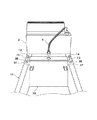
沸騰強化板50は、麺カゴ3に向けて強い沸騰力を与えるとともに、予熱タンクが設置される、貯湯槽の奥部のお湯を、より集中して加熱、沸騰させるためのものである。沸騰強化板50は、図4に示すように、貯湯槽10の底板より一回り小さい平板51と、平板51の下面に設けられた複数の仕切り板55を有する。平板51の、麺カゴ3の各々の下方に当たる部分には、開口52が開けられている。好ましくは、開口52は、横方向に長い長孔で、麺カゴ3の真下からやや奥寄りに開けられている。
Further, in order to compensate for such a decrease in the temperature of hot water on the back side of the
The boiling
仕切り板55は、左右方向に延びる板であり、この例では、平板の前後端と、その間の2か所に取り付けられている。図5に示すように、これらの仕切り板55によって、平板51と貯湯槽10の底板との間に空間が形成され、さらに、この空間が、縦に並ぶ3個の区画S11、S12、S13(前区画、中央区画、奥区画)に区切られる。この例では、前区画S11と中央区画S12の長さL1、L2(前後方向長さ)は等しいが、奥区画S13の長さL3は、これらの区画よりも長くなっている。
The
このような沸騰強化板50を設けると、平板51の下方の空間内においてお湯が熱源により集中的に加熱されて沸騰し、沸騰したお湯が平板51の開口52から貯湯槽10内に噴出される。麺カゴ3は、これらの開口52の上方に配置されているため、沸騰したお湯が集中して麺カゴ3に当たり、沸騰力(カゴ3内の麺をゆでる、あるいは、撹拌させる力)が強くなる。さらに、前述のように、開口52は麺カゴ3の真下よりもやや奥寄りに開けられているため、沸騰したお湯は、貯湯槽10の奥方向へ流れやすくなる。
また、前述のように、熱源20は、貯湯槽10の前後方向における中央付近(中央区画S12)の加熱力が高くなる構造を有している。そこで、熱源20からより高い加熱力で加熱された中央区画S12内のお湯が開口52から奥方向へ流れることになる。
When such a boiling strengthening
Further, as described above, the
さらに、奥区画S13の長さL3を長くしたことにより、奥区画S13により広い面積の熱源20が接することになり、奥区画S13に優先的に沸騰水を配分できる。
このように貯湯槽10の奥側での沸騰力を高めることにより、奥側に予熱タンク30を設置したことによるお湯の温度低下を防ぐことができる。
Furthermore, by increasing the length L3 of the back section S13, the
Thus, by raising the boiling power on the back side of the hot
なお、平板51の中央の仕切り板52は前後方向に移動可能、あるいは、脱着可能に取り付けられることが好ましい。
The
次に、図6、図7を参照して、本発明の第2の実施の形態に係るゆで麺機を説明する。
このゆで麺機は、図1のゆで麺機と同じ構造を有するが、さらに、貯湯槽10内の湯面を覆うとともに麺カゴを保持するカゴ受け板60を備える。以下、カゴ受け板60の構造とその作用について説明する。
Next, a boiled noodle machine according to a second embodiment of the present invention will be described with reference to FIGS.
This boiled noodle machine has the same structure as the boiled noodle machine of FIG. 1, but further includes a
カゴ受け板60は、図7に示すように、四方が壁で囲まれた凹状の覆板部61と、覆板部61の左右縁から斜め外方向へ張り出す外縁部65とを有する。両外縁部65を貯湯槽10の両側板の上面に設置することにより、覆板部61が貯湯槽10の湯面の上方を覆うように設置される。そして、覆板部61が、貯湯槽10内のお湯の湯熱により加温される。覆板部61には、麺カゴ3を貯湯槽10に入れて置くためのカゴ置き開口部62が分散して開けられている。この例では、開口部62は縦方向に2列、横方向に3列、等間隔で並んでいる。さらに、覆板部61の手前側の2隅には、開口63が開けられている。
As shown in FIG. 7, the
このようなカゴ受け板60を設けることにより、貯湯槽10内のお湯から発する熱が、カゴ受け板60と湯面との間の空間に留まって大気中に逃げないので、お湯の保温効果が得られる。
さらに、図6に示すように、予熱タンク30内で加温された差し湯は、各とい35から覆板部61内に流れ出し、同部の上面を流れて開口63から貯湯槽10の手前側内部に滴下する。覆板部61は、貯湯槽10内のお湯の熱を受けて加熱されているので、この差し湯は、覆板部61の上面を流れる間に昇温する。一例では、予熱タンク30から供給されるお湯の温度が90℃程度の場合、95℃程度に加温される。
By providing such a
Furthermore, as shown in FIG. 6, the hot water heated in the preheating
1 ゆで麺機 2 本体
3 麺カゴ 4 差し水パイプ
5 オーバーフロー排水口 6 オーバーフロー排出管
7 給水コック
10 貯湯槽 11 排水口
12 排水管 14 ヘッド
15 凸部
20 熱源 21、22 誘導加熱コイル
30 予熱タンク 31 本体
32、33 ガイド板 35 開口
36 とい 37 係合片
38 スリット 41 蓋
42 開口
50 沸騰強化板 51 平板
52 開口 55 仕切り板
60 カゴ受け板 61 覆板部
62 カゴ置き開口部 63 開口
65 外縁部
DESCRIPTION OF SYMBOLS 1
Claims (3)
該貯湯槽内の湯を加熱する熱源と、
を備えるゆで麺機であって、
さらに、前記貯湯槽に供給する差し水又は差し湯を予熱する、前記貯湯槽に浸漬される予熱タンクを具備し、
前記予熱タンクの上縁部の両端に切り欠き又は凸部が形成されており、
前記貯湯槽の上部の奥部に、前記切り欠き又は凸部が係合する凸部又は切り欠きが形成されており、
前記切り欠きを前記凸部に係合させることにより、前記予熱タンクが前記貯湯槽に、着脱容易かつ浮き上がらないように取り付けられることを特徴とするゆで麺機。 A hot water tank for storing hot water to boil the noodles,
A heat source for heating the hot water in the hot water tank;
A boiled noodle machine equipped with
Furthermore, the preheating tank immersed in the said hot water storage tank which preheats the hot water or hot water supplied to the said hot water storage tank is comprised,
Notches or protrusions are formed at both ends of the upper edge of the preheating tank,
In the upper part of the hot water tank, a convex part or a notch is formed to engage the notch or convex part,
By engaging the notch on the convex portion, the preheating tank the hot water storage tank, noodle machine characteristic and to Ruyu that is attached so as not detachable easily and float.
該貯湯槽内の湯を加熱する熱源と、
を備えるゆで麺機であって、
前記貯湯槽に供給する差し水又は差し湯を予熱する、前記貯湯槽に浸漬される予熱タンクを具備し、
さらに、前記貯湯槽の底板上に設置される沸騰強化板を備え、
該沸騰強化板が、
前記底板からある寸法を隔てて該底板を覆うように広がり、麺カゴの下方近傍に開口が形成された平板と、
該平板の下面から下方に延びる、該平板と前記貯湯槽の底板間の空間を複数の区画に仕切る仕切り板と、
を有し、
前記仕切り板が、前記予熱タンクに近い位置に優先的に沸騰水を噴出するように配置されていることを特徴とするゆで麺機。 A hot water tank for storing hot water to boil the noodles,
A heat source for heating the hot water in the hot water tank;
A boiled noodle machine equipped with
A preheating tank immersed in the hot water storage tank for preheating the hot water or hot water supplied to the hot water storage tank;
In addition, a boiling strengthening plate installed on the bottom plate of the hot water tank,
The boiling reinforcement plate is
A flat plate with an opening formed in the vicinity of the lower part of the noodle basket, spreading so as to cover the bottom plate with a certain distance from the bottom plate,
A partition plate that extends downward from the lower surface of the flat plate, and partitions the space between the flat plate and the bottom plate of the hot water storage tank into a plurality of compartments;
Have
The partition plate, noodle machine characteristic and to Ruyu that are arranged to eject preferentially boiling water at a position closer to the preheating tank.
該貯湯槽内の湯を加熱する熱源と、
を備えるゆで麺機であって、
前記貯湯槽に供給する差し水又は差し湯を予熱する、前記貯湯槽に浸漬される予熱タンクを具備し、
さらに、前記貯湯槽の上側に配置された、麺カゴを受けるカゴ受け板を備え、
前記カゴ受け板が、
前記貯湯槽内の湯面上を覆い、湯熱により加温される覆板部と、
該覆板部の複数箇所に分散して形成された、前記麺カゴを前記貯湯槽に入れて置くためのカゴ置き開口部と、
前記覆板部に形成された、該覆板部の上面を流して昇温した湯(差し湯)を前記貯湯槽内へと導く供給口部と、
を有し、
前記予熱タンクから、前記カゴ受け板の覆板部上に差し湯を供給することを特徴とするゆで麺機。 A hot water tank for storing hot water to boil the noodles,
A heat source for heating the hot water in the hot water tank;
A boiled noodle machine equipped with
A preheating tank immersed in the hot water storage tank for preheating the hot water or hot water supplied to the hot water storage tank;
Furthermore, provided with a basket receiving plate that is disposed on the upper side of the hot water tank and receives a noodle basket,
The basket backing plate is
Covering the hot water surface in the hot water tank, and a cover plate portion heated by hot water;
A basket placing opening for dispersing and forming the noodle basket in the hot water storage tank formed in a plurality of locations of the cover plate portion;
A supply port portion that is formed in the cover plate portion, and that feeds hot water (hot water) that is heated by flowing through the upper surface of the cover plate portion, into the hot water storage tank;
Have
Wherein the preheating tank, noodle machine characteristic and to Ruyu to supply hot water insert on the covering plate portion of the cage receiving plate.
Priority Applications (1)
| Application Number | Priority Date | Filing Date | Title |
|---|---|---|---|
| JP2009092590A JP5320135B2 (en) | 2009-04-07 | 2009-04-07 | Boiled noodle machine |
Applications Claiming Priority (1)
| Application Number | Priority Date | Filing Date | Title |
|---|---|---|---|
| JP2009092590A JP5320135B2 (en) | 2009-04-07 | 2009-04-07 | Boiled noodle machine |
Publications (2)
| Publication Number | Publication Date |
|---|---|
| JP2010240176A JP2010240176A (en) | 2010-10-28 |
| JP5320135B2 true JP5320135B2 (en) | 2013-10-23 |
Family
ID=43093946
Family Applications (1)
| Application Number | Title | Priority Date | Filing Date |
|---|---|---|---|
| JP2009092590A Active JP5320135B2 (en) | 2009-04-07 | 2009-04-07 | Boiled noodle machine |
Country Status (1)
| Country | Link |
|---|---|
| JP (1) | JP5320135B2 (en) |
Families Citing this family (3)
| Publication number | Priority date | Publication date | Assignee | Title |
|---|---|---|---|---|
| CN102429575A (en) * | 2011-10-24 | 2012-05-02 | 深圳市巨鹏厨房设备有限公司 | Electric noodle stewing stove |
| CN110101297A (en) * | 2019-06-10 | 2019-08-09 | 成都市唯真智能餐饮管理有限责任公司 | The poaching devices of automatic cooking device |
| CN113827112B (en) * | 2021-09-23 | 2023-04-07 | 广东粤有厨业科技有限公司 | Noodle cooking machine with physical heat dissipation and steam condensation |
Family Cites Families (4)
| Publication number | Priority date | Publication date | Assignee | Title |
|---|---|---|---|---|
| JPS5549683Y2 (en) * | 1977-05-24 | 1980-11-19 | ||
| JPH0333993U (en) * | 1989-08-11 | 1991-04-03 | ||
| JPH0670844A (en) * | 1992-08-28 | 1994-03-15 | Osaka Gokou:Kk | Noodle boiling machine |
| JPH08243020A (en) * | 1995-03-11 | 1996-09-24 | Osaka Gas Co Ltd | Noodle heating device |
-
2009
- 2009-04-07 JP JP2009092590A patent/JP5320135B2/en active Active
Also Published As
| Publication number | Publication date |
|---|---|
| JP2010240176A (en) | 2010-10-28 |
Similar Documents
| Publication | Publication Date | Title |
|---|---|---|
| JP6297190B2 (en) | Boiled noodle machine | |
| CA2871441C (en) | Flame resistant cooking grate and cooking apparatus | |
| JPWO2013140773A1 (en) | Cooker | |
| JP2006158970A (en) | Griddle for cooking foodstuff | |
| JP5320135B2 (en) | Boiled noodle machine | |
| KR20120133090A (en) | cooling function improved oil and water type frying apparatus | |
| JP4257306B2 (en) | Boiled noodle machine | |
| JP2015181870A (en) | Noodle boiling machine | |
| JP2017099595A (en) | Grill device and container support body | |
| JP4909007B2 (en) | Noodle boiled kettle | |
| JP4909008B2 (en) | Noodle boiled kettle | |
| JP6682117B2 (en) | Boiler for noodles | |
| JP5468331B2 (en) | Cooking net and heating cooker provided with the same | |
| JP2012024445A (en) | Noodle boiling apparatus | |
| KR101264271B1 (en) | Cooking device for nuddles | |
| JP2009201591A (en) | Kitchen apparatus | |
| JP3673839B2 (en) | Water heater used in the kitchen | |
| JP3225312B2 (en) | Multipurpose pot | |
| JP3227791U (en) | Food warmer | |
| JP2024042436A (en) | boiled noodle machine | |
| JP2011130988A (en) | Noodle boiler | |
| KR20060128101A (en) | Steam generating apparatus and cooking apparatus having the same | |
| JP6140489B2 (en) | Noodle bowl | |
| JP2010249330A (en) | Cooker | |
| JP6249475B2 (en) | Boiled noodle equipment |
Legal Events
| Date | Code | Title | Description |
|---|---|---|---|
| A621 | Written request for application examination |
Free format text: JAPANESE INTERMEDIATE CODE: A621 Effective date: 20111222 |
|
| A977 | Report on retrieval |
Free format text: JAPANESE INTERMEDIATE CODE: A971007 Effective date: 20130314 |
|
| A131 | Notification of reasons for refusal |
Free format text: JAPANESE INTERMEDIATE CODE: A131 Effective date: 20130319 |
|
| A521 | Request for written amendment filed |
Free format text: JAPANESE INTERMEDIATE CODE: A523 Effective date: 20130403 |
|
| TRDD | Decision of grant or rejection written | ||
| A01 | Written decision to grant a patent or to grant a registration (utility model) |
Free format text: JAPANESE INTERMEDIATE CODE: A01 Effective date: 20130709 |
|
| A61 | First payment of annual fees (during grant procedure) |
Free format text: JAPANESE INTERMEDIATE CODE: A61 Effective date: 20130712 |
|
| R150 | Certificate of patent or registration of utility model |
Ref document number: 5320135 Country of ref document: JP Free format text: JAPANESE INTERMEDIATE CODE: R150 Free format text: JAPANESE INTERMEDIATE CODE: R150 |
|
| R250 | Receipt of annual fees |
Free format text: JAPANESE INTERMEDIATE CODE: R250 |
|
| R250 | Receipt of annual fees |
Free format text: JAPANESE INTERMEDIATE CODE: R250 |
|
| R250 | Receipt of annual fees |
Free format text: JAPANESE INTERMEDIATE CODE: R250 |
|
| R250 | Receipt of annual fees |
Free format text: JAPANESE INTERMEDIATE CODE: R250 |
|
| R250 | Receipt of annual fees |
Free format text: JAPANESE INTERMEDIATE CODE: R250 |
|
| R250 | Receipt of annual fees |
Free format text: JAPANESE INTERMEDIATE CODE: R250 |
|
| R250 | Receipt of annual fees |
Free format text: JAPANESE INTERMEDIATE CODE: R250 |
|
| R250 | Receipt of annual fees |
Free format text: JAPANESE INTERMEDIATE CODE: R250 |