JP5319085B2 - Fuel cap with valve mounted on the same surface - Google Patents
Fuel cap with valve mounted on the same surface Download PDFInfo
- Publication number
- JP5319085B2 JP5319085B2 JP2007172588A JP2007172588A JP5319085B2 JP 5319085 B2 JP5319085 B2 JP 5319085B2 JP 2007172588 A JP2007172588 A JP 2007172588A JP 2007172588 A JP2007172588 A JP 2007172588A JP 5319085 B2 JP5319085 B2 JP 5319085B2
- Authority
- JP
- Japan
- Prior art keywords
- body portion
- fuel
- cap
- fuel tank
- valve
- Prior art date
- Legal status (The legal status is an assumption and is not a legal conclusion. Google has not performed a legal analysis and makes no representation as to the accuracy of the status listed.)
- Expired - Fee Related
Links
- 239000000446 fuel Substances 0.000 title claims description 135
- 239000002828 fuel tank Substances 0.000 claims description 68
- 210000000078 claw Anatomy 0.000 description 20
- 230000002093 peripheral effect Effects 0.000 description 14
- 230000008602 contraction Effects 0.000 description 7
- 239000007788 liquid Substances 0.000 description 7
- 230000005540 biological transmission Effects 0.000 description 5
- 238000011144 upstream manufacturing Methods 0.000 description 4
- 230000008878 coupling Effects 0.000 description 3
- 238000010168 coupling process Methods 0.000 description 3
- 238000005859 coupling reaction Methods 0.000 description 3
- 238000002347 injection Methods 0.000 description 3
- 239000007924 injection Substances 0.000 description 3
- 238000004804 winding Methods 0.000 description 2
- 230000004888 barrier function Effects 0.000 description 1
- 238000010586 diagram Methods 0.000 description 1
- 230000014509 gene expression Effects 0.000 description 1
- 230000037431 insertion Effects 0.000 description 1
- 238000003780 insertion Methods 0.000 description 1
- 239000004071 soot Substances 0.000 description 1
- 230000007704 transition Effects 0.000 description 1
Images


Classifications
-
- B—PERFORMING OPERATIONS; TRANSPORTING
- B62—LAND VEHICLES FOR TRAVELLING OTHERWISE THAN ON RAILS
- B62J—CYCLE SADDLES OR SEATS; AUXILIARY DEVICES OR ACCESSORIES SPECIALLY ADAPTED TO CYCLES AND NOT OTHERWISE PROVIDED FOR, e.g. ARTICLE CARRIERS OR CYCLE PROTECTORS
- B62J35/00—Fuel tanks specially adapted for motorcycles or engine-assisted cycles; Arrangements thereof
-
- B—PERFORMING OPERATIONS; TRANSPORTING
- B60—VEHICLES IN GENERAL
- B60K—ARRANGEMENT OR MOUNTING OF PROPULSION UNITS OR OF TRANSMISSIONS IN VEHICLES; ARRANGEMENT OR MOUNTING OF PLURAL DIVERSE PRIME-MOVERS IN VEHICLES; AUXILIARY DRIVES FOR VEHICLES; INSTRUMENTATION OR DASHBOARDS FOR VEHICLES; ARRANGEMENTS IN CONNECTION WITH COOLING, AIR INTAKE, GAS EXHAUST OR FUEL SUPPLY OF PROPULSION UNITS IN VEHICLES
- B60K15/00—Arrangement in connection with fuel supply of combustion engines or other fuel consuming energy converters, e.g. fuel cells; Mounting or construction of fuel tanks
- B60K15/03—Fuel tanks
- B60K15/04—Tank inlets
- B60K15/0406—Filler caps for fuel tanks
-
- B—PERFORMING OPERATIONS; TRANSPORTING
- B60—VEHICLES IN GENERAL
- B60K—ARRANGEMENT OR MOUNTING OF PROPULSION UNITS OR OF TRANSMISSIONS IN VEHICLES; ARRANGEMENT OR MOUNTING OF PLURAL DIVERSE PRIME-MOVERS IN VEHICLES; AUXILIARY DRIVES FOR VEHICLES; INSTRUMENTATION OR DASHBOARDS FOR VEHICLES; ARRANGEMENTS IN CONNECTION WITH COOLING, AIR INTAKE, GAS EXHAUST OR FUEL SUPPLY OF PROPULSION UNITS IN VEHICLES
- B60K15/00—Arrangement in connection with fuel supply of combustion engines or other fuel consuming energy converters, e.g. fuel cells; Mounting or construction of fuel tanks
- B60K15/03—Fuel tanks
- B60K15/04—Tank inlets
Landscapes
- Engineering & Computer Science (AREA)
- Mechanical Engineering (AREA)
- Life Sciences & Earth Sciences (AREA)
- Sustainable Development (AREA)
- Sustainable Energy (AREA)
- Chemical & Material Sciences (AREA)
- Combustion & Propulsion (AREA)
- Transportation (AREA)
- Cooling, Air Intake And Gas Exhaust, And Fuel Tank Arrangements In Propulsion Units (AREA)
- Closures For Containers (AREA)
Description
本発明は、フューエルキャップに係り、特に、車両及びエンジン駆動機器と共に用いられるフューエルキャップに関する。 The present invention relates to a fuel cap, and more particularly, to a fuel cap used with a vehicle and an engine drive device.
自動二輪車用フューエルキャップの多くは、燃料タンク内の燃料が使われたときにその容積を置き換える空気を取り込むためのチェックバルブを備えている(例えば、特許文献1〜11参照)。このようなチェックバルブは、多くの場合、フューエルキャップの底面ではなく、上面近く、又は、少なくとも上面により近いところ、に配置されている。チェックバルブをフューエルキャップの上面近くに配置することは、多くの場合望ましい。なぜなら、燃料タンクの上面よりも上方にチェックバルブが位置することになるため、燃料タンク表面上の液体(例えば雨)が空気と共に燃料タンク内に「滴り(したたり)」落ちることを防ぐことができるからである。また、自動二輪車用のフューエルキャップには、「樋(とい)」を備えたものが多い。チェックバルブに流入する空気は、上方へ向けて方向転換する前に、樋の下を通らなければならない。このフューエルキャップの樋は、液体がチェックバルブと接触して燃料タンク内に浸入することを防ぐバリアとして機能する。
本発明は、同一面取付された(flush−mount)バルブ付きフューエルキャップを提供するものである。 The present invention provides a fuel cap with a flush-mount valve.
本発明の第一の態様は、燃料タンクの注入口を塞ぐように構成されたフューエルキャップである。このフューエルキャップは、上記燃料タンクの注入口と係合するように構成された本体部分を有する。この本体部分は、中心軸を規定する。上記フューエルキャップは、更に、上記本体部分に連結されたバルブを有する。このバルブにより、上記本体部分に空気流を選択的に通過させることができる。上記フューエルキャップは、更に、上記本体部分に連結されたキャップカバーを有する。このキャップカバーは、上記中心軸に沿って、上記本体部分に対して相対的に移動可能である。 The first aspect of the present invention is a fuel cap configured to close an injection port of a fuel tank. The fuel cap has a body portion configured to engage with the fuel tank inlet. This body portion defines a central axis. The fuel cap further has a valve coupled to the body portion. This valve allows an air flow to selectively pass through the body portion. The fuel cap further includes a cap cover coupled to the main body portion. The cap cover is movable relative to the main body portion along the central axis.
本発明の第二の態様は、燃料注入口とフューエルキャップとを備えた燃料タンクを有する燃料タンクアッセンブリである。上記燃料注入口は、上記燃料タンクの上面に設けられ、上記フューエルキャップは、上記燃料注入口と係合可能である。上記フューエルキャップは、バルブを有する。このバルブにより、上記フューエルキャップに空気流を選択的に通過させることができる。上記フューエルキャップが上記燃料注入口に係合されているとき、上記フューエルキャップの上部は、上記燃料タンクの上面と略同一面に揃っている。上記フューエルキャップが上記燃料注入口に係合されているとき、上記バルブは、上記燃料タンクの上面よりも下方に位置している。 The second aspect of the present invention is a fuel tank assembly having a fuel tank provided with a fuel inlet and a fuel cap. The fuel inlet is provided on the upper surface of the fuel tank, and the fuel cap is engageable with the fuel inlet. The fuel cap has a valve. This valve allows an air flow to selectively pass through the fuel cap. When the fuel cap is engaged with the fuel inlet, the upper portion of the fuel cap is substantially flush with the upper surface of the fuel tank. When the fuel cap is engaged with the fuel inlet, the valve is positioned below the upper surface of the fuel tank.
本発明の第三の態様は、燃料タンクの注入口を塞ぐように構成されたフューエルキャップである。このフューエルキャップは、上記燃料タンクの注入口と係合するように構成された本体部分を有する。この本体部分は、中心軸を規定する。上記フューエルキャップは、更に、上記本体部分に連結され、上記中心軸に沿って上記本体部分に対して相対的に移動可能な可動部分を有する。この可動部分は、貫通路を備えている。上記フューエルキャップは、更に、バルブを有する。このバルブにより、上記本体部分及び上記可動部分の貫通路に空気流を選択的に通過させることができる。 A third aspect of the present invention is a fuel cap configured to close an injection port of a fuel tank. The fuel cap has a body portion configured to engage with the fuel tank inlet. This body portion defines a central axis. The fuel cap further includes a movable portion that is coupled to the main body portion and is movable relative to the main body portion along the central axis. This movable part is provided with a through path. The fuel cap further has a valve. By this valve, an air flow can be selectively passed through the passage of the main body portion and the movable portion.
本発明の他の特徴及び態様は、発明の詳細な説明及び添付図面から明らかである。 Other features and aspects of the present invention will be apparent from the detailed description of the invention and the accompanying drawings.
本発明によれば、同一面取付されたバルブ付きフューエルキャップが提供される。 According to the present invention, a fuel cap with a valve mounted on the same surface is provided.
本発明のいくつかの実施例を詳細に説明する前に理解して頂きたいのは、本発明の適用は、以下の説明又は添付図面に示された構成要素の具体的な構成及び配置に限定されるものではない、という点である。本発明は、他の実施形態も採ることができるとともに、様々な方法で実現する又は実行されることが可能である。また、ここで用いられている表現や用語は、説明するためのものであって、限定するものと解釈されるべきではない。「含む」、「有する」、又は「備える」、及びこれらの派生語は、これらの語の後に列挙された要素及びその等価物だけでなくそれらとは別の要素をも包含することが意図されてここでは用いられている。特段明記又は限定されていない限り、「取り付けられた」、「接続された」、「支持された」、及び「連結された」という用語並びにこれらの派生語は、広義に用いられており、直接的な取付、接続、支持、及び、結合だけでなく、間接的な取付、接続、支持、及び、連結をも包含する。さらに、「接続された」及び「連結された」は、物理的又は機械的な接続又は連結に限定されない。 Before describing some embodiments of the present invention in detail, it should be understood that the application of the present invention is limited to the specific configurations and arrangements of the components shown in the following description or the attached drawings. It is a point that is not done. The invention is capable of other embodiments and of being practiced or carried out in various ways. Also, the expressions and terms used herein are for the purpose of explanation and should not be construed as limiting. “Including”, “having” or “comprising” and derivatives thereof are intended to encompass not only the elements listed after these words and their equivalents, but also other elements. Is used here. Unless otherwise stated or limited, the terms “attached”, “connected”, “supported”, and “coupled” and their derivatives are used in a broad sense and are directly This includes not only general attachment, connection, support and coupling, but also indirect attachment, connection, support and coupling. Further, “connected” and “coupled” are not limited to physical or mechanical connections or couplings.
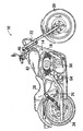
図1に示した自動二輪車10は、駆動アッセンブリ12と、フレーム18と、フロントフォーク・アッセンブリ22と、スイングアーム・アッセンブリ又はリアフォーク・アッセンブリ26と、前輪30と、後輪34と、シート38と、燃料タンク42と、を有する。フレーム18は、駆動アッセンブリ12と、フロントフォーク・アッセンブリ22と、リアフォーク・アッセンブリ26と、シート38と、燃料タンク42と、を支持する。フロントフォーク・アッセンブリ22は、自動二輪車10の前端に枢支され、前輪30を支持する。フロントフォーク・アッセンブリ22は、自動二輪車10を操舵するための1組のハンドルバー46を備える。リアフォーク・アッセンブリ26は、自動二輪車10の後端において、フレーム18に連結され、後輪34を回動可能に支持する。シート38は、フレーム18に連結され、ライダー(自動二輪車10の運転者/操縦者)を支持するように構成される。燃料タンク42は、フレーム18によって支持され、駆動アッセンブリ12へ燃料を供給する。
The
駆動アッセンブリ14は、自動二輪車10の前輪30と後輪34の間においてフレーム18に連結される。この駆動アッセンブリ14がフレーム18に連結される位置は、シート38の真下であることが好ましい。引き続き図1を参照すると、駆動アッセンブリ14は、エンジン50と、トランスミッション54と、を備える。エンジン50及びトランスミッション54は、駆動アッセンブリ14のそれぞれ別個の独立した複数の構成要素を備えている。エンジン50は、トランスミッション54よりも車両前方側においてフレーム18によって支持された、V形ツインエンジンであることが好ましい。エンジン50は、図示しない出力軸(例えば、クランクシャフト)を備える。この出力軸は、従来通りの方法で一次チェーン(図示せず)を駆動してトランスミッション54に動力を伝える一次ドライブスプロケット(図示せず)を備える。
The
図7〜8を参照する。燃料タンク42は、燃料注入口58を備える。この燃料注入口58は、フューエルキャップ62によって選択的に塞ぐことができる。このようなスタイルのフューエルキャップ62は、一般的に、「同一面取付(flush−mount)」フューエルキャップとして知られる。なぜなら、フューエルキャップ62の上部は、通常、燃料タンク42の上面66の輪郭や、燃料タンク42に連結され、燃料注入口58を囲むベゼル(表縁)70の輪郭に従うからである。図7に示すように、フューエルキャップ62の上部は燃料タンク42の上面66と完全には揃えられていないが、ベゼル70が、燃料タンク42の上面66を効果的に延長させ、上面66からフューエルキャップ62の上部への略スムーズな移行を実現させていることを考慮すると、フューエルキャップ62の上部は、燃料タンク42の上面66と略同一面に揃えられていると言える。
Please refer to FIGS. The
図2を参照する。図2には、フューエルキャップ62の分解斜視図が示されている。フューエルキャップ62は、通常、中心軸78を備えた本体部分74と、本体部分74に連結され、中心軸78に沿って本体部分74に対して相対的に動くことが可能な可動部分又は伸縮部分82と、伸縮部分82に連結され、伸縮部分82と共に中心軸78に沿って本体部分74に対して相対的に動くことが可能なキャップカバー86と、を備える。燃料タンク42のベゼル70及び/又は上面66に対して同一面取付を実現するために、キャップカバー86及び伸縮部分82は、引き出し位置と引き込み位置との間を移動可能なように構成される。引き出し位置(図5参照)において、キャップカバー86は、燃料タンク42の上面66よりも実質的に上方に位置し、引き込み位置(図6参照)において、キャップカバー86の上面88は、ベゼル70(或いは、燃料タンク42の上面66)の輪郭に略従っている。
Please refer to FIG. FIG. 2 shows an exploded perspective view of the
図2を参照する。本体部分74は、燃料注入口58に形成された雌ネジ94と螺合するように構成された雄ネジ90を備える(図7〜8も参照のこと)。本体部分74の上端104近くには円環状の溝102が形成され、この溝102にOリング(オーリング)98が嵌め込まれることによって、フューエルキャップ62が燃料注入口58にねじこまれたときに、本体部分74と燃料注入口58との間がシール(密閉)される。Oリング98の代わりに、他の種類の弾性シールを用いてフューエルキャップ62を燃料注入口58に対してシールしてもよい。
Please refer to FIG. The
図6を参照する。伸縮部分82の外径D1は、伸縮部分82が本体部分74内に引っ込むように又は収容されるように、本体部分74の内径D2よりも小さい。伸縮部分82の外周面106と本体部分74の内周面110との間の半径方向隙間G1は、伸縮部分82が本体部分74内で自由に動くことができるのに十分な程度の大きさである。ただし、図2に示すように、軸方向に延びる複数のガイド部材114が伸縮部分82の外周面106から隆起しており、本体部分74の内周面110と係合して、伸縮部分82を中心軸78に略心合わせする。本実施例に係るフューエルキャップ62において、伸縮部分82は、伸縮部分82の外周面106まわりに等しい角度間隔で配置された3つのガイド部材114を備える。別の実施形態として、伸縮部分82が4つ以上のガイド部材114を備えるようにすることも可能である。
Please refer to FIG. The outer diameter D1 of the
図5及び6を参照する。本体部分74は、中心軸78に向けて半径方向内側へ延びる複数の内部突起(又は、キー)118を備える。キー118は、伸縮部分82に設けられた対応する溝(又は、キー溝)122と係合するように構成される(図2、3、及び8も参照のこと)。図には1つのキーしか描かれていないが、本体部分74は、本体部分74の内周面110まわりに等しい角度間隔で配置された3つのキー118を備えており、伸縮部分82は、伸縮部分82の外周面106まわりに等しい角度間隔で配置された3つのキー溝122を備えている。さらに、本実施例に係るフューエルキャップ62において、ガイド部材114は、伸縮部分82においてキー溝122に隣接して配置される(図2参照)。別の実施形態として、本体部分74及び伸縮部分82が3つよりも多い又は少ないキー118及びキー溝122をそれぞれ備えているようにしてもよく、キー溝122は、ガイド部材114から離間して配置されてもよい。
Reference is made to FIGS. The
図2、3、及び、8を参照する。複数のキー溝122の各々は、伸縮部分82の外周面106に形成された窪み126に向かって開放している。本実施例に係るフューエルキャップ62において、窪み126の各々は、対応するキー溝122から伸縮部分82の上面130に向けて上方に延在している。別の実施形態として、窪み126の各々が伸縮部分82の上面130に達する前に終端となり、窪み126が伸縮部分82の上面130から露出しないようにしてもよい。加えて、窪み126の各々は、窪み126内に開放したキー溝122の各々に隣接した隆起部分134によって形成されてもよい。
Reference is made to FIGS. Each of the plurality of
図3を参照する。図3には、キャップカバー86を伸縮部分82へ連結させるための多重構造が示されている。伸縮部分82は、伸縮部分82の内周面142から中心軸78に向けて半径方向内側へ延び、軸方向に延在する複数の突起138を備える。また、伸縮部分82は、複数の突起138のそれぞれの間に、伸縮部分82の内周面142から中心軸78に向けて半径方向内側へ延びる複数のガイド部材146を備える。図3に示すように、突起138は、ガイド部材146よりもより半径方向内側まで延びている。本実施例に係るフューエルキャップ62において、伸縮部分82は、等しい角度間隔で配置された4つの突起138と、それぞれの突起138の間に配置された3つのガイド部材146と、を備えている。別の実施形態として、伸縮部分82が、4つより多い又は少ない突起138と、そのような突起138のそれぞれの間に設けられた3つより多い又は少ないガイド部材とを備えるようにしてもよい。
Please refer to FIG. FIG. 3 shows a multiple structure for connecting the
引き続き図3を参照する。伸縮部分82は、伸縮部分82の上面130から上方へ延びる複数の弓状ツメ150を備える。複数のツメ150は、互いに略等しい隙間G2(図4参照)を空けて配置される。このことの重要性は後述する。複数のツメ150の各々は、その遠心端に、傾斜部分154を備える。傾斜部分154は、伸縮部分82の上面130に対して傾いた斜面158と、上面130に略平行な橋脚面158と、を備える。
Still referring to FIG. The
キャップカバー86は、キャップカバー86の底面170から軸方向に延びる受入部分166を備える。図3に示すように、受入部分166の形状は略円筒形であり、受入委部分166には軸方向に延びる複数のスロット174が形成されている。複数のスロット174の各々は、キャップカバー86の底面170から受入部分166の遠心端まで延在する。このことの重要性は後述する。本実施例に係るフューエルキャップ62において、キャップカバー86は、等しい角度間隔で配置され、伸縮部分82の4つの突起138に対応した、4つのスロット174を備えている。別の実施形態として、伸縮部分82に設けられた突起138の数に応じて、キャップカバー86の受入部分166に形成されるスロット174の数も4つより多くても少なくてもよい。
The
引き続き図3を参照する。キャップカバー86は、更に、キャップカバー86の底面170から延びる複数の弓状ツメ178を備えている。伸縮部分82のツメ150と同様に、弓状ツメ178の各々も、その遠心端に傾斜部分182を備え、傾斜部分182は、キャップカバー86の底面170に対して傾いた斜面186と、中心軸78に直交する面と略平行な橋脚面190と、を備える。本実施例に係るフューエルキャップ62において、キャップカバー86は、等しい角度間隔で配置された4つの弓状ツメ178を備える。複数のツメ178の各々は、受入部分166(図4参照)の複数のスロット174の幅に略対応した隙間G3を空けて離間している。さらに、図3及び4に示すように、隙間G3の各々は、受入部分166のスロット174の各々とそれぞれ略位置が合っており、キャップカバー86の底面170に形成された複数の浅い流路又は溝194は、複数のスロット174の各々を隙間G3の各々へそれぞれ連通させる。
Still referring to FIG. The cap cover 86 further includes a plurality of
図2、5、及び6を参照する。フューエルキャップ62は、ほぼ本体部分74内に配置されたバルブ・アッセンブリ198を備える。バルブ・アッセンブリ198は、本体部分74の下端206近くに配置されたバルブ202を備える。本実施例に係るフューエルキャップ62において、バルブ202は、燃料タンク42内の燃料が消費されるときに「置換空気」を燃料タンク42内に流入させつつ、液体燃料や気化した燃料がバルブ202を通じて燃料タンク42外に流出することを十分に防ぐことができるように、逆止弁として構成される。図2、5、及び6に示すように、伸縮部分82は、伸縮部分82を貫通し、伸縮部分82が本体部分74内に収容されたときにバルブ・アッセンブリ198を受け入れる通路234を備える。したがって、置換空気は、バルブ202に到達する前に、通路234を通過する。
Reference is made to FIGS. The
図2を参照する。バルブ202は、シール210と、コイルスプリング218によってシール210に対して付勢されたダイヤフラム214と、を備える。本実施例に係るフューエルキャップ62において、シール210は、ダイヤフラム214の外径D4よりも小さい内径D3を持つ、略平坦なリングとして構成される。別の実施形態として、逆止弁202は、添付図面に示したものとは異なる構成のものであってもよい。
Please refer to FIG. The
本実施例に係るフューエルキャップ62において、バルブ・アッセンブリ198は、更に、バルブ本体222を備える。バルブ本体222は、上方へ延びる導管(又は、「スノーケル」)226を備える(図2、5、及び6参照)。バルブ・アッセンブリ198は、更に、底面カバー230を備える。底面カバー230は、本体部分74において、バルブ202と、バルブ本体222とを支持する。図5及び6を参照すると、底面カバー230は、円筒形受入部分234を備える。円筒形受入部分234は、円筒形受入部分234の内周まわりに延在する環状溝238を備える。バルブ本体222の下端には、バルブ本体222の下端の外周まわりに延在する縁246を備える。バルブ本体222の下端は、受入部分234内に受け入れられ、バルブ本体222は、縁246と溝238との係合によって、底面カバー230に固定される。別の実施形態として、異なる構造を用いて、底面カバー230をバルブ本体222へ固定することも可能である。
In the
引き続き図5及び6を参照する。シール210は、バルブ本体222と、受入部分234の内周から半径方向内側へ延びる縁250との間に挟まれる。次いで、ダイヤフラム214が、シール210と、底面カバー230に形成されたバネ座254との間に挟まれる。図5及び6に示すように、コイルスプリング218は、バネ座254に置かれ、ダイヤフラム214をシール210に対して付勢する。底面カバー230は、バネ座254を囲む複数の開口部258を備える。
Continuing to refer to FIGS. The
図2、5、及び6を参照する。底面カバー230は、更に、環状溝262と、複数の弓状ツメ270と、を備える。環状溝262は、底面カバー230を本体部分74に対してシールするシール(例えば、Oリング266)を受け入れるように構成される。複数の弓状ツメ270は、本体部分74の内周面110から半径方向内側へ延びる複数の縁部分278の各々とそれぞれ係合する複数の傾斜部分274を備える。別の実施形態として、バルブ本体222、シール210、底面カバー230、又は、これらの任意の組み合わせなどのバルブ・アッセンブリ198の複数の部分は、それぞれ別体とされずに、一個のものとして一体化して形成されてもよい。
Reference is made to FIGS. The
引き続き図2、5、及び6を参照する。コイルスプリング282は、バルブ本体222と、伸縮部分82との間に配置され、伸縮部分82を上方へ且つ逆止弁202から離れる方向へ付勢する。特に、コイルスプリング282の下端は、バルブ本体222上に形成されたバネ座286上に支持され、コイルスプリング282の上端は、伸縮部分82の内面のうちバルブ本体222のバネ座286と向かい合う部分に形成された円筒形溝290内において支持される。
Continuing to refer to FIGS. The
図2を参照する。バルブ・アッセンブリ198は、本体部分74に連結される前に、予備組立される。バルブ・アッセンブリ198を予備組立するには、まず、コイルスプリング218が、底面カバー230上のバネ座254内に下げられる。次いで、ダイヤフラム214がコイルスプリング218上へ下げられる。次に、シール210が、底面カバー230の受入部分234の縁250上に下げられる。そして、最後に、バルブ本体222が受入部分234内に挿入され、上述のように、縁246と溝238とが係合する。このようなバルブ・アッセンブリ198の予備組立の最初の工程又は最後の工程として、底面カバー230の溝262にOリング266を嵌め込んでもよい。このようにして、バルブ・アッセンブリ198は完全に一体化され、一個の部材として取り扱うことができる。
Please refer to FIG. The
フューエルキャップ62の組立を完了させるために、本体部分74の下端206を通って、伸縮部分82が本体部分74内に挿入される。伸縮部分82は、伸縮部分82が引き出し位置まで上方へスライドできるように、キー溝122が本体部分74のキー118と位置が合うような向きにされる。次いで、コイルスプリング282の上端が円筒形溝290に座るように、コイルスプリング218が伸縮部分82内に挿入される。次いで、バルブ・アッセンブリ198が本体部分74内に挿入され、底面カバー230の複数のツメ270の各々と本体部分74の複数の縁部分278の各々とをそれぞれ係合させることによって、バルブ・アッセンブリ198が本体部分74に連結される。
In order to complete the assembly of the
最後に、キャップカバー86が伸縮部分82と連結される。キャップカバー86と伸縮部分82とを連結させるとき、キャップカバー86は、まず、受入部分166の複数のスロット174が伸縮部分82の複数の対応する突起138と位置が合うような向きに向けられる。次いで、受入部分166は、伸縮部分82内へ向けて軸方向に押圧され、複数の突起138の各々が複数のスロット174の各々を通ってスライドする。このとき、ガイド部材146が、受入部分166の外周面と係合して、伸縮部分82における受入部分166の更なる位置合わせと支持とが提供される。受入部分166を伸縮部分82内へ更に挿入させると、複数の弓状ツメ150の斜面150の各々と複数の弓状ツメ178の斜面186の各々とがそれぞれ互いに係合して、伸縮部分82の複数の弓状ツメ150を半径方向内側へ反らせる。受入部分166の伸縮部分82内への挿入が完了すると、複数の弓状ツメ150は変形前の形状へ跳ね返り、複数の弓状ツメ150の橋脚面162の各々と複数の弓状ツメ178の橋脚面190の各々とがそれぞれ互いに係合して、キャップカバー86が伸縮部分82から外れたり、取れたりすることを防ぐことができる。
Finally, the
図5及び6を参照する。バルブ・アッセンブリ198は、概して、逆止弁202によって分離された上流チャンバ294と下流チャンバ298とを備える。既述のように、逆止弁202により、燃料が消費されるときに、選択的に、置換空気を燃料注入口58を通過させ、燃料タンク42内へ流入させることができる。より具体的には、上流チャンバ294と下流チャンバ298との間の圧力差がコイルスプリング218の張力に打ち勝つほど大きく、よって、ダイヤフラム214が軸方向下方へ動き、シール210から離れるときに、置換空気が燃料タンク42内に流入する。バルブ・アッセンブリ198の上流チャンバ294の圧力と下流チャンバ298の圧力とが等しくなると、コイルスプリング218の張力によりダイヤフラム214が再びシール210に座る。図5及び6に示すように、スノーケル226が、本体部分74の上端104よりも上方に位置する取込口302を通じて上記のような置換空気を取り込む。
Reference is made to FIGS. The
キャップカバー86上の特徴と伸縮部分82上の特徴とが組み合わされることにより、置換空気がスノーケル226の取込口302に到達する前に通過しなければならない迷路のような流路又は曲がりくねった流路が形成される。図3を参照すると、キャップカバー86の底面170から延びる複数の同心壁310a、310b、310cと、本体部分74の上端104上の複数の同心壁314a、314b、314cとが組み合わさって、上述の曲がりくねった流路の一部が形成される。特に、中間壁314bは、置換空気が通過できるように、等しい角度間隔で配置された複数の隙間G4(図4参照)を備える。
The combination of features on the
図6を参照する。本体部分74上の中間壁314bは、伸縮部分82及びキャップカバー86が引き込み位置に動いたとき、キャップカバー86上の同心壁310aと310bの間にちょうど嵌る。換言すれば、キャップカバー86上の同心壁310a及び310bの遠心端は、本体部分74上の同心壁314a、314b、314cの遠心端よりも下方に位置し、これにより、置換空気が半径方向において最も外側の流路318aから半径方向において最も内側の流路318d(図7参照)まで連続して通過することができる複数の同心流路318a〜318dが形成される。また、置換空気は、流路318bから隙間G4(図4参照)を経由して流路318dへ流れることもできる。
Please refer to FIG. The
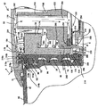
流路318a〜318dを連続して通過した後、置換空気は、複数の弓状ツメ178の間の隙間G3と、隙間G3と位置に揃えられている(図4参照)複数の弓状ツメ150の間の隙間G2とを通過する。図3及び7に示すように、キャップカバー86の底面170に形成された溝194は、壁310a、310b、314a、314b、314cを受入部分166の内面と相互に係合させることによって、又は、壁310a、310b、314a、314b、314cを受入部分166の内側に収容させることによって形成された、半径方向において最も内側の流路318dと連通する。スノーケル226の取込口302は、受入部分166の内側から置換空気を引き込むために、受入部分166の内部に向けて開いている。まとめると、曲がりくねった流路は、置換空気に、置換空気がスノーケル226の取込口302を通じて必要に応じて取り込まれる場所である受入部分166の内部に到達する前に、半径方向において最も外側の流路318aから半径方向において最も内側の流路318dまで、位置合わせされた隙間G3及びG2と、受入部分166の複数のスロット174を通って、流路318a〜318dを通過することを要求する。図7の矢印Aは、上述の曲がりくねった流路を通って、スノーケル226を下って、逆止弁202を通って、フューエルキャップ62の底面カバー230の開口部258を通って、そして、燃料タンク42内に流入する置換空気の流れを示している。
After continuously passing through the
引き続き図7を参照すると、燃料タンク42の燃料注入口58を塞ぐ引き込み位置にあるフューエルキャップ62が図示されている。引き込み位置において、キャップカバー86の上面88は、ベゼル70の輪郭、又は、燃料タンク42の上面66の輪郭に略従い、同一面取付スタイルを実現している。図7に示すように、スノーケル226の取込口302は、燃料タンク42の上面66よりも上方の位置から置換空気を引き込むために、燃料タンク42の上面66よりも上方に配置される。結果として、燃料タンク42の上面66上の雨などの液体がスノーケル226内に滴り落ちて、置換空気と一緒に燃料タンク42内に流入してしまうことを実質的に防ぐことができる。受入部分166の流路318a〜318d、隙間G2、G3、及び、複数のスロット174によって形成された上述の迷路のような又は曲がりくねった流路が、受入部分166の内部に液体が滴り落ちることを困難にしつつ、スノーケル226の取込口302を燃料タンク42の上面66よりも上方のレベルに配置することによって、受入部分166の内部からスノーケル226内へ流入することも困難にしている。上述の曲がりくねった流路から液体が漏れ、受入部分166の内部に滴り落ちた場合、本体部分74の底に落ちて、本体部分74とバルブ・アッセンブリ198との間に集まる又は溜まる可能性が高い。このようにして集まった液体は、フューエルキャップ62を燃料注入口58から取り外して逆さまにすることによって、本体部分74の内周面110と伸縮部分82の外周面106との間の半径方向隙間G1を通してフューエルキャップ62から排出させることができる。
With continued reference to FIG. 7, the
図8aを参照する。フューエルキャップ62を燃料注入口58から取り外すためには、まず、フューエルキャップ62を引き出し位置に動かす必要がある。フューエルキャップ62を引き込み位置から引き出し位置まで動かすには、まず、キャップカバー86をコイルスプリング218の付勢力に抗して下方へ押し下げて、複数の窪み126の各々に隣接した複数の隆起部分134の各々を、本体部分74上の半径方向内側に延びる複数のキー118の各々との係合状態から外す。次いで、図8bに示すように、キャップカバー86を反時計回りに少し(例えば、約10度)回して、複数のキー118の各々を伸縮部分82の複数のキー溝122の各々にそれぞれ位置合わせする。次いで、図8cに示すように、複数のキー118の各々が複数のキー溝122の各々とそれぞれ位置が揃うと、コイルスプリング218の伸縮部分82に対する付勢力により、伸縮部分82は複数のキー溝122の各々の端面322(図3も参照のこと)が複数のキー118の各々と接触するまで、上方へ延びる。そして、フューエルキャップ62を回して螺合を外すと、燃料注入口58から取り外すことができる。
Refer to FIG. In order to remove the
フューエルキャップ62を再び取り付けるには、まず、Oリング98が本体部分74を燃料注入口58に対してシールするまで、フューエルキャップ62を燃料注入口58へねじ込む。次いで、複数の窪み126の各々に隣接した複数の隆起部分134の各々が本体部分74上の複数のキー118の各々よりも下方に位置するようになるまで、キャップカバー86をコイルスプリング218の付勢力に抗して下方へ押し下げる。次いで、キャップカバー86を時計回りに少し(例えば、約10度)回して、伸縮部分82の複数のキー溝122の各々を動かし、本体部分74の複数のキー118の各々にそれぞれ位置が合った状態からずらす。そして、キャップカバー86から手を放す。複数の隆起部分134の各々は、複数のキー118の各々を、隣接した複数の窪み126の各々においてそれぞれ保持し、キャップカバー86が意図せずに反時計回りに回転してしまうことを実質的に防止し、フューエルキャップ62を引き込み位置に保持する。
To reinstall the
本発明は、車両及びエンジン駆動機器と共に用いられるフューエルキャップに適用可能である。 The present invention is applicable to a fuel cap used with a vehicle and an engine drive device.
10 自動二輪車
12 駆動アッセンブリ
18 フレーム
22 フロントフォーク・アッセンブリ
26 リアフォーク・アッセンブリ
30 前輪
34 後輪
38 シート
42 燃料タンク
46 ハンドルバー
50 エンジン
54 トランスミッション
58 燃料注入口
62 フューエルキャップ
70 ベゼル
74 本体部分
78 中心軸
82 伸縮部分
86 キャップカバー
98 Oリング
102 円環状溝
114 ガイド部材
118 キー
122 キー溝
126 窪み
134 隆起部分
138 突起
146 ガイド部材
150 ツメ
166 受入部分
174 スロット
178 ツメ
198 バルブ・アッセンブリ
202 バルブ
210 シール
214 ダイヤフラム
218 コイルスプリング
222 バルブ本体
226 スノーケル
230 底面カバー
234 円筒形受入部分
238 環状溝
254 バネ座
262 環状溝
266 Oリング
282 コイルスプリング
286 バネ座
290 円筒形溝
294 上流チャンバ
298 下流チャンバ
310a、310b 同心壁
314a、314b、314c 同心壁
318a〜318d 流路
DESCRIPTION OF
Claims (23)
前記燃料タンクの前記注入口と係合するように構成される本体部分と、
該本体部分に連結されるバルブと、
前記本体部分に連結されるキャップカバーとを含み、
前記本体部分は、中心軸を定め、
前記バルブは、前記本体部分を通じて前記燃料タンクに流入する空気流を選択的に許容し、
前記キャップカバーは、前記中心軸に沿って、前記本体部分に対して移動可能である、
フューエルキャップ。 A fuel cap configured to close the fuel tank inlet;
A body portion configured to engage with the inlet of the fuel tank;
A valve coupled to the body portion;
A cap cover coupled to the body portion;
The body portion defines a central axis;
The valve is selectively permit the flow of air flowing into the fuel tank through said body portion,
The cap cover is movable with respect to the main body portion along the central axis.
Fuel cap.
フューエルキャップとを含む、
燃料タンクアッセンブリであって、
前記燃料タンクは、前記燃料タンクの上面に燃料注入口を含み、
前記フューエルキャップは、前記燃料注入口と係合可能であり、
前記フューエルキャップは、
前記フューエルキャップを通じて前記燃料タンクに流入する空気流を選択的に許容するバルブと、
前記燃料注入口と係合可能であり、且つ、中心軸を定める本体部分と、
該本体部分に連結され、且つ、前記中心軸に沿って、前記本体部分に対して移動可能なキャップカバーとを含み、
前記バルブは、前記本体部分に連結され、且つ、前記本体部分を通じる前記空気流を選択的に許容し、
前記フューエルキャップが前記燃料注入口に係合されるとき、前記フューエルキャップの上部は、前記燃料タンクの上面と実質的に整列され、
前記フューエルキャップが前記燃料注入口に係合されるとき、前記バルブは、前記燃料タンクの前記上面よりも下方に位置付けられる、
燃料タンクアッセンブリ。 A fuel tank,
Including fuel cap,
A fuel tank assembly,
The fuel tank includes a fuel inlet on an upper surface of the fuel tank,
The fuel cap is engageable with the fuel inlet;
The fuel cap is
A valve for selectively permitting air flow flowing into the fuel tank through the fuel cap,
A body portion engageable with the fuel inlet and defining a central axis;
A cap cover coupled to the body portion and movable relative to the body portion along the central axis;
The valve is coupled to the body portion and selectively allows the air flow through the body portion;
When the fuel cap is engaged with the fuel inlet, the top of the fuel cap is substantially aligned with the upper surface of the fuel tank;
When the fuel cap is engaged with the fuel inlet, the valve is positioned below the upper surface of the fuel tank;
Fuel tank assembly.
前記燃料注入口と係合可能な第一の本体部分と、
該第一の本体部分に連結される第二の本体部分と、
該第二の本体部分に連結されるキャップカバーとを含み、
前記第一の本体部分は、中心軸を定め、
前記第二の本体部分は、前記中心軸に沿って、前記第一の本体部分に対して移動可能であり、
前記キャップカバーは、前記中心軸に沿って、前記第二の本体部分と共に移動可能である、
請求項10に記載の燃料タンクアッセンブリ。 The fuel cap is
A first body portion engageable with the fuel inlet;
A second body portion coupled to the first body portion;
A cap cover coupled to the second body portion;
The first body portion defines a central axis;
The second body portion is movable relative to the first body portion along the central axis;
The cap cover is movable with the second body portion along the central axis.
The fuel tank assembly according to claim 10.
前記燃料タンクの前記注入口と係合するように構成される本体部分と、
該本体部分に連結される可動部分と、
前記本体部分に連結されるバルブとを含み、
前記本体部分は、中心軸を定め、
前記可動部分は、前記中心軸に沿って、前記可動部分の少なくとも一部が前記本体部分の外側に位置付けられる第一位置と、前記可動部分が前記本体部分の内側に位置付けられる第二位置との間で、前記本体部分に対して移動可能であり、
前記可動部分は、貫通する通路を有し、
前記バルブは、選択的に前記本体部分及び前記可動部分の前記通路を通じて前記燃料タンクに流入する空気流を選択的に許容する、
フューエルキャップ。 A fuel cap configured to close the fuel tank inlet;
A body portion configured to engage with the inlet of the fuel tank;
A movable part coupled to the body part;
A valve coupled to the body portion;
The body portion defines a central axis;
The movable part has a first position where at least a part of the movable part is positioned outside the main body part and a second position where the movable part is positioned inside the main body part along the central axis. Is movable relative to the body portion,
The movable part has a passage therethrough;
The valve selectively permitting airflow flowing into the fuel tank through the passageway selectively said body portion and said movable portion,
Fuel cap.
Applications Claiming Priority (2)
| Application Number | Priority Date | Filing Date | Title |
|---|---|---|---|
| US11/427,813 US20080000906A1 (en) | 2006-06-30 | 2006-06-30 | Flush-mount fuel cap with valve |
| US11/427,813 | 2006-06-30 |
Publications (2)
| Publication Number | Publication Date |
|---|---|
| JP2008013170A JP2008013170A (en) | 2008-01-24 |
| JP5319085B2 true JP5319085B2 (en) | 2013-10-16 |
Family
ID=38777198
Family Applications (1)
| Application Number | Title | Priority Date | Filing Date |
|---|---|---|---|
| JP2007172588A Expired - Fee Related JP5319085B2 (en) | 2006-06-30 | 2007-06-29 | Fuel cap with valve mounted on the same surface |
Country Status (3)
| Country | Link |
|---|---|
| US (2) | US20080000906A1 (en) |
| JP (1) | JP5319085B2 (en) |
| DE (1) | DE102007030023A1 (en) |
Families Citing this family (7)
| Publication number | Priority date | Publication date | Assignee | Title |
|---|---|---|---|---|
| US8910815B2 (en) * | 2008-04-14 | 2014-12-16 | Ti Group Automotive Systems, L.L.C. | Cover for fuel system component and method of making |
| US8353418B2 (en) | 2010-07-23 | 2013-01-15 | Bemis Manufacturing Company | Pressure relief cap |
| US8555865B2 (en) * | 2010-09-08 | 2013-10-15 | Caterpillar Inc. | Fuel cap breather apparatus |
| FR2993224B1 (en) * | 2012-07-12 | 2015-09-04 | Valeo Systemes Dessuyage | DEVICE FOR MAINTAINING A PIPE, IN PARTICULAR A WASHER FLUID |
| DE112015002177T5 (en) * | 2014-05-09 | 2017-01-19 | Harley-Davidson Motor Company Group, LLC | Fuel tank assembly with adjusted ventilation |
| JP6277969B2 (en) * | 2014-05-28 | 2018-02-14 | 豊田合成株式会社 | Lubrication device |
| USD852444S1 (en) | 2016-08-16 | 2019-06-25 | Unger Marketing International, Llc | Bottle |
Family Cites Families (37)
| Publication number | Priority date | Publication date | Assignee | Title |
|---|---|---|---|---|
| US3815776A (en) * | 1972-06-26 | 1974-06-11 | Mccord Corp | Gas cap assembly |
| US4133346A (en) * | 1977-06-06 | 1979-01-09 | General Motors Corporation | Pressure vacuum relief valve |
| JPS5855102Y2 (en) * | 1979-01-09 | 1983-12-16 | 川崎重工業株式会社 | Fuel evaporation gas treatment device for motorcycle fuel tanks |
| ZA8064B (en) | 1979-01-24 | 1981-01-28 | Shaw Mfg Ltd | Load supporting roller assemblies |
| JPS59175049A (en) | 1983-03-22 | 1984-10-03 | Seiko Instr & Electronics Ltd | Substrate for photomagnetic disc |
| JPS59175049U (en) * | 1983-05-07 | 1984-11-22 | 川崎重工業株式会社 | fuel tank cap |
| JPH07110629B2 (en) * | 1985-02-28 | 1995-11-29 | ヤマハ発動機株式会社 | Vehicle fuel tank cap mounting device |
| DE3527773A1 (en) * | 1985-08-02 | 1987-02-12 | Bayerische Motoren Werke Ag | DEVICE FOR REFUELING FUEL TANKS OF MOTOR VEHICLES, IN PARTICULAR MOTORCYCLES |
| US4653711A (en) * | 1985-11-22 | 1987-03-31 | Marshell Edward L | Automotive vehicle fuel tank cap hanger |
| JPH034627Y2 (en) * | 1985-12-14 | 1991-02-06 | ||
| US4693393A (en) * | 1986-04-09 | 1987-09-15 | General Motors Corporation | Fuel vapor storage canister having tortuous vent passage |
| US4666058A (en) * | 1986-05-30 | 1987-05-19 | Stant Inc. | Off-road vehicle fuel cap |
| US4676390A (en) * | 1986-07-22 | 1987-06-30 | Stant Inc. | Pressure-release fuel cap |
| JP2508486B2 (en) | 1987-06-08 | 1996-06-19 | ソニー株式会社 | Backlight compensation circuit for video camera |
| US4807472A (en) * | 1987-07-31 | 1989-02-28 | Harley-Davidson, Inc. | Motorcycle fuel level gauge |
| JPH034627A (en) | 1989-06-01 | 1991-01-10 | Nec Eng Ltd | Mobile telephone communication relay system |
| JP2881311B2 (en) | 1989-07-28 | 1999-04-12 | 味の素株式会社 | Anti-human BCDF monoclonal antibody and method for quantifying human BCDF using the same |
| JP2508486Y2 (en) * | 1989-10-20 | 1996-08-21 | 本田技研工業株式会社 | Tank cap |
| JP2779234B2 (en) * | 1989-11-06 | 1998-07-23 | ヤマハ発動機株式会社 | Fuel tank breather device |
| US5158123A (en) * | 1991-02-19 | 1992-10-27 | Senko Robert D | Fluid fill cap |
| JPH05246367A (en) * | 1992-03-06 | 1993-09-24 | Yamaha Motor Co Ltd | Fuel tank cap with breather mechanism |
| US5167340A (en) * | 1992-04-13 | 1992-12-01 | Shaw Aero Devices, Inc. | Fuel cap with a molded seal |
| JP3353330B2 (en) * | 1992-04-30 | 2002-12-03 | 本田技研工業株式会社 | Fuel tank cap |
| JP3275511B2 (en) * | 1994-02-15 | 2002-04-15 | スズキ株式会社 | Breather device for fuel tank for transportation means |
| JP3656917B2 (en) * | 1994-06-11 | 2005-06-08 | 本田技研工業株式会社 | Spark arrester device for vehicle exhaust system |
| JP3616686B2 (en) | 1996-02-29 | 2005-02-02 | カルソニックカンセイ株式会社 | Tank cap |
| US6349842B1 (en) * | 1996-06-19 | 2002-02-26 | Heinrich Reutter | Cover fastenable on a container connection |
| US6209745B1 (en) * | 1999-06-04 | 2001-04-03 | Jansson And Associates Masterbuilders, Inc. | Pop up flush-mount gas cap |
| JP4334062B2 (en) * | 1999-06-07 | 2009-09-16 | 本田技研工業株式会社 | Fuel tank seal structure for motorcycle fuel tank |
| CA2371908C (en) * | 1999-09-10 | 2006-07-11 | Stant Manufacturing Inc. | Fuel tank closure with cap ejector spring |
| US6648160B2 (en) * | 2001-07-17 | 2003-11-18 | Matthew Jon Hotch | Flush fuel cap |
| JP5170606B2 (en) | 2001-07-27 | 2013-03-27 | 東洋製罐株式会社 | Cap with dispensing nozzle |
| US6745914B2 (en) * | 2001-11-26 | 2004-06-08 | Toyoda Gosei., Ltd. | Cap device |
| JP3645866B2 (en) | 2002-03-26 | 2005-05-11 | カルソニックカンセイ株式会社 | Tank cap |
| US6983814B2 (en) * | 2003-07-11 | 2006-01-10 | Harley-Davidson Motor Company Group, Inc. | Oil tank cap |
| WO2006050845A1 (en) * | 2004-11-09 | 2006-05-18 | Reutter Metallwarenfabrik Gmbh | Safety closure for steam-pressurized containers of household appliances |
| US8353418B2 (en) * | 2010-07-23 | 2013-01-15 | Bemis Manufacturing Company | Pressure relief cap |
-
2006
- 2006-06-30 US US11/427,813 patent/US20080000906A1/en not_active Abandoned
-
2007
- 2007-06-29 JP JP2007172588A patent/JP5319085B2/en not_active Expired - Fee Related
- 2007-06-29 DE DE102007030023A patent/DE102007030023A1/en not_active Withdrawn
-
2013
- 2013-02-01 US US13/756,647 patent/US8807375B2/en active Active
Also Published As
| Publication number | Publication date |
|---|---|
| JP2008013170A (en) | 2008-01-24 |
| DE102007030023A1 (en) | 2008-01-03 |
| US20130200078A1 (en) | 2013-08-08 |
| US20080000906A1 (en) | 2008-01-03 |
| US8807375B2 (en) | 2014-08-19 |
Similar Documents
| Publication | Publication Date | Title |
|---|---|---|
| JP5319085B2 (en) | Fuel cap with valve mounted on the same surface | |
| US6626060B2 (en) | Bicycle cable connector for splicing two cables in series | |
| CA2584927C (en) | A body for actuating a standpipe of a replaceable filter element | |
| US7640909B2 (en) | Vehicle with variable air intake arrangement | |
| TWI684716B (en) | Transmission for bicycle | |
| CN102791994B (en) | Vehicle speed sensor mounting structure | |
| CN106838401A (en) | Valve gear | |
| EP1925809B1 (en) | Vehicle | |
| JP5771651B2 (en) | Fuel cap with breather mechanism | |
| US8839973B2 (en) | Fuel inlet device with a cap member for a fuel tank | |
| JP5795179B2 (en) | Evaporative fuel processing device for vehicle | |
| US9834090B2 (en) | Fuel tank assembly with triggered venting | |
| US20080283463A1 (en) | Filter with protruding member for engaging valve in head | |
| US8042515B2 (en) | Throttle device | |
| US20080283464A1 (en) | Filter assembly with valve requiring compliant filter for open flow path | |
| KR100921666B1 (en) | Automotive shut-off device and valve assembly for shut-off type LP container | |
| JP2007292148A (en) | Check valve | |
| US7481320B2 (en) | Filter device having a bi-directional valve | |
| ITRM940774A1 (en) | MECHANISM TO OPERATE A DEVICE IN AN INTERNAL COMBUSTION ENGINE | |
| JP2022173931A (en) | Operation valve | |
| WO2019025696A1 (en) | Pressure regulating device and method for assembling same, for a fuel vapour absorber | |
| CN100417792C (en) | Secondary air introduction device for two-wheeled motor vehicles | |
| JP5116761B2 (en) | Filter unit | |
| US7559565B2 (en) | Suspension restrain device | |
| CN217456189U (en) | Bicycle seat post structure and bicycle |
Legal Events
| Date | Code | Title | Description |
|---|---|---|---|
| A621 | Written request for application examination |
Free format text: JAPANESE INTERMEDIATE CODE: A621 Effective date: 20100426 |
|
| A131 | Notification of reasons for refusal |
Free format text: JAPANESE INTERMEDIATE CODE: A131 Effective date: 20120327 |
|
| A601 | Written request for extension of time |
Free format text: JAPANESE INTERMEDIATE CODE: A601 Effective date: 20120611 |
|
| A602 | Written permission of extension of time |
Free format text: JAPANESE INTERMEDIATE CODE: A602 Effective date: 20120614 |
|
| A521 | Request for written amendment filed |
Free format text: JAPANESE INTERMEDIATE CODE: A523 Effective date: 20120726 |
|
| A131 | Notification of reasons for refusal |
Free format text: JAPANESE INTERMEDIATE CODE: A131 Effective date: 20121218 |
|
| A601 | Written request for extension of time |
Free format text: JAPANESE INTERMEDIATE CODE: A601 Effective date: 20130311 |
|
| A602 | Written permission of extension of time |
Free format text: JAPANESE INTERMEDIATE CODE: A602 Effective date: 20130314 |
|
| A521 | Request for written amendment filed |
Free format text: JAPANESE INTERMEDIATE CODE: A523 Effective date: 20130416 |
|
| TRDD | Decision of grant or rejection written | ||
| A01 | Written decision to grant a patent or to grant a registration (utility model) |
Free format text: JAPANESE INTERMEDIATE CODE: A01 Effective date: 20130618 |
|
| A61 | First payment of annual fees (during grant procedure) |
Free format text: JAPANESE INTERMEDIATE CODE: A61 Effective date: 20130711 |
|
| R150 | Certificate of patent or registration of utility model |
Ref document number: 5319085 Country of ref document: JP Free format text: JAPANESE INTERMEDIATE CODE: R150 Free format text: JAPANESE INTERMEDIATE CODE: R150 |
|
| R250 | Receipt of annual fees |
Free format text: JAPANESE INTERMEDIATE CODE: R250 |
|
| R250 | Receipt of annual fees |
Free format text: JAPANESE INTERMEDIATE CODE: R250 |
|
| R250 | Receipt of annual fees |
Free format text: JAPANESE INTERMEDIATE CODE: R250 |
|
| R250 | Receipt of annual fees |
Free format text: JAPANESE INTERMEDIATE CODE: R250 |
|
| R250 | Receipt of annual fees |
Free format text: JAPANESE INTERMEDIATE CODE: R250 |
|
| R250 | Receipt of annual fees |
Free format text: JAPANESE INTERMEDIATE CODE: R250 |
|
| R250 | Receipt of annual fees |
Free format text: JAPANESE INTERMEDIATE CODE: R250 |
|
| R250 | Receipt of annual fees |
Free format text: JAPANESE INTERMEDIATE CODE: R250 |
|
| LAPS | Cancellation because of no payment of annual fees |