JP5317633B2 - Fixing device - Google Patents
Fixing device Download PDFInfo
- Publication number
- JP5317633B2 JP5317633B2 JP2008288944A JP2008288944A JP5317633B2 JP 5317633 B2 JP5317633 B2 JP 5317633B2 JP 2008288944 A JP2008288944 A JP 2008288944A JP 2008288944 A JP2008288944 A JP 2008288944A JP 5317633 B2 JP5317633 B2 JP 5317633B2
- Authority
- JP
- Japan
- Prior art keywords
- frequency
- power
- control mode
- predetermined
- temperature
- Prior art date
- Legal status (The legal status is an assumption and is not a legal conclusion. Google has not performed a legal analysis and makes no representation as to the accuracy of the status listed.)
- Expired - Fee Related
Links
- 238000010438 heat treatment Methods 0.000 claims description 79
- 230000006698 induction Effects 0.000 claims description 39
- 238000001514 detection method Methods 0.000 claims description 24
- 239000003990 capacitor Substances 0.000 claims description 5
- 238000000034 method Methods 0.000 description 17
- 238000010586 diagram Methods 0.000 description 5
- 230000003247 decreasing effect Effects 0.000 description 4
- 229910052745 lead Inorganic materials 0.000 description 4
- 230000005674 electromagnetic induction Effects 0.000 description 3
- 229910052774 Proactinium Inorganic materials 0.000 description 2
- 230000007423 decrease Effects 0.000 description 2
- 229910052721 tungsten Inorganic materials 0.000 description 2
- 229910052777 Praseodymium Inorganic materials 0.000 description 1
- 239000000919 ceramic Substances 0.000 description 1
- 229910052736 halogen Inorganic materials 0.000 description 1
- 150000002367 halogens Chemical class 0.000 description 1
- 239000000463 material Substances 0.000 description 1
- 239000002184 metal Substances 0.000 description 1
- 229910052751 metal Inorganic materials 0.000 description 1
Images


Classifications
-
- G—PHYSICS
- G03—PHOTOGRAPHY; CINEMATOGRAPHY; ANALOGOUS TECHNIQUES USING WAVES OTHER THAN OPTICAL WAVES; ELECTROGRAPHY; HOLOGRAPHY
- G03G—ELECTROGRAPHY; ELECTROPHOTOGRAPHY; MAGNETOGRAPHY
- G03G15/00—Apparatus for electrographic processes using a charge pattern
- G03G15/20—Apparatus for electrographic processes using a charge pattern for fixing, e.g. by using heat
- G03G15/2003—Apparatus for electrographic processes using a charge pattern for fixing, e.g. by using heat using heat
- G03G15/2014—Apparatus for electrographic processes using a charge pattern for fixing, e.g. by using heat using heat using contact heat
- G03G15/2039—Apparatus for electrographic processes using a charge pattern for fixing, e.g. by using heat using heat using contact heat with means for controlling the fixing temperature
- G03G15/205—Apparatus for electrographic processes using a charge pattern for fixing, e.g. by using heat using heat using contact heat with means for controlling the fixing temperature specially for the mode of operation, e.g. standby, warming-up, error
-
- H—ELECTRICITY
- H05—ELECTRIC TECHNIQUES NOT OTHERWISE PROVIDED FOR
- H05B—ELECTRIC HEATING; ELECTRIC LIGHT SOURCES NOT OTHERWISE PROVIDED FOR; CIRCUIT ARRANGEMENTS FOR ELECTRIC LIGHT SOURCES, IN GENERAL
- H05B6/00—Heating by electric, magnetic or electromagnetic fields
- H05B6/02—Induction heating
- H05B6/10—Induction heating apparatus, other than furnaces, for specific applications
- H05B6/14—Tools, e.g. nozzles, rollers, calenders
-
- G—PHYSICS
- G03—PHOTOGRAPHY; CINEMATOGRAPHY; ANALOGOUS TECHNIQUES USING WAVES OTHER THAN OPTICAL WAVES; ELECTROGRAPHY; HOLOGRAPHY
- G03G—ELECTROGRAPHY; ELECTROPHOTOGRAPHY; MAGNETOGRAPHY
- G03G15/00—Apparatus for electrographic processes using a charge pattern
- G03G15/20—Apparatus for electrographic processes using a charge pattern for fixing, e.g. by using heat
- G03G15/2003—Apparatus for electrographic processes using a charge pattern for fixing, e.g. by using heat using heat
- G03G15/2014—Apparatus for electrographic processes using a charge pattern for fixing, e.g. by using heat using heat using contact heat
-
- G—PHYSICS
- G03—PHOTOGRAPHY; CINEMATOGRAPHY; ANALOGOUS TECHNIQUES USING WAVES OTHER THAN OPTICAL WAVES; ELECTROGRAPHY; HOLOGRAPHY
- G03G—ELECTROGRAPHY; ELECTROPHOTOGRAPHY; MAGNETOGRAPHY
- G03G2215/00—Apparatus for electrophotographic processes
- G03G2215/20—Details of the fixing device or porcess
- G03G2215/2003—Structural features of the fixing device
- G03G2215/2016—Heating belt
- G03G2215/2025—Heating belt the fixing nip having a rotating belt support member opposing a pressure member
- G03G2215/2032—Heating belt the fixing nip having a rotating belt support member opposing a pressure member the belt further entrained around additional rotating belt support members
Description
本発明は、画像形成装置における誘導加熱方式の定着装置に関する。 The present invention relates to an induction heating type fixing device in an image forming apparatus.
一般に画像形成装置においては、記録材に転写されたトナー像を定着させるための定着器が備えられている。定着器としては、従来セラミックヒーターやハロゲンヒーターによる加熱方式が多く用いられていたが、近年では電磁誘導加熱方式が用いられるようになってきた(例えば特許文献1参照)。 Generally, an image forming apparatus is provided with a fixing device for fixing a toner image transferred onto a recording material. Conventionally, a heating method using a ceramic heater or a halogen heater has been often used as the fixing device, but in recent years, an electromagnetic induction heating method has been used (see, for example, Patent Document 1).
誘導加熱方式を用いた定着器に給電する電源装置の電力制御時の簡単な周波数制御方法を図13に示す。ステップ4001及び4002において検出電力Pと目標電力Poを比較する。P>Poの場合はステップ4005において周波数をある所定の値faだけ上げ、P<Poの場合はステップ4004において周波数をある所定の値fbだけ下げる。P=Poの場合はステップ4003において周波数を維持する。
FIG. 13 shows a simple frequency control method at the time of power control of the power supply device that supplies power to the fixing device using the induction heating method. In
また、定着器の温度制御時の簡単な周波数制御方法を図14に示す。ステップ5001及びステップ5002において検出温度Tと目標温度Toを比較する。T>Toの場合はステップ5005において周波数をある所定の値faだけ上げ、T<Toの場合はステップ5004において周波数をある所定の値fbだけ下げる。T=Toの場合はステップ5003において周波数を維持する。
FIG. 14 shows a simple frequency control method for controlling the temperature of the fixing device. In step 5001 and
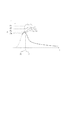
図15に駆動周波数fと電力Pの関係を示す。図15に示すように、共振周波数f1のときにコイル71に最大電力Pmaxが供給される。共振周波数f1を中心として高周波側及び低周波側に周波数が変化すると供給電力が減少する特性がある。従って、この共振周波数f1よりも周波数の高いfhの領域のスロープを用いて駆動周波数fを制御することによって、電力制御が可能となる。
しかしながら、周波数制御方式においては、電力を低くするためには共振周波数から外してコイルに電力を供給するスイッチ素子の駆動周波数を高くすることになる。しかし、共振周波数から外れて駆動周波数が高くなるとスイッチ素子のスイッチング損失が増大してしまう。共振周波数から外れた状態で大電力動作をする場合は特に顕著である。 However, in the frequency control method, in order to reduce the power, the drive frequency of the switch element that supplies power to the coil is increased from the resonance frequency. However, when the drive frequency increases beyond the resonance frequency, the switching loss of the switch element increases. This is particularly noticeable when high power operation is performed in a state deviating from the resonance frequency.
また、スイッチング素子に供給する直流電圧の変化だけで電力を制御する直流電圧制御方式においては、昇圧回路と降圧回路の両方が必要になり、大きなコストアップやサイズアップにつながってしまう。 In addition, in the DC voltage control system that controls power only by changing the DC voltage supplied to the switching element, both a booster circuit and a step-down circuit are required, leading to a large increase in cost and size.
そこで、本発明は、コストアップやサイズアップを抑えつつ、大電力動作時のスイッチ素子の損失も軽減する定着装置を提供することを目的とする。 SUMMARY An advantage of some aspects of the invention is that it provides a fixing device that reduces the loss of a switch element during a high-power operation while suppressing an increase in cost and size.
上記課題を解決するために、本発明の定着装置は、誘導加熱方式により加熱を行う定着装置であって、導電性発熱体を含む加熱部材を加熱するための誘導加熱コイルと、交流電源を整流して得られる直流電圧を昇圧する昇圧回路と、前記昇圧回路の出力が供給され、前記誘導加熱コイルに高周波電流を供給するスイッチ素子と、前記スイッチ素子を駆動する駆動回路と、前記加熱部材の温度を検出する温度検出手段と、前記温度検出手段により検出された温度が目標温度となるように前記昇圧回路の昇圧比と前記駆動回路による前記スイッチ素子の駆動周波数を制御することにより前記誘導加熱コイルへ供給する電力を制御する制御部と、を有し、前記制御部は、前記昇圧回路の昇圧比を前記所定昇圧比に固定した状態で所定周波数以上の範囲で前記スイッチ素子の駆動周波数を変化させる第1の制御モードと、前記スイッチ素子の駆動周波数を前記所定周波数に固定した状態で前記昇圧回路の昇圧比を所定昇圧比以上の範囲で変化させる第2の制御モードとを選択的に実行するものであり、前記制御部は、前記第1の制御モードが選択されている状態で、前記温度検出手段により検出された温度が前記目標温度よりも低い場合、該温度が検出された時に設定されている駆動周波数を所定量低くした値が前記所定周波数より低くなるならば、前記第1の制御モードから第2の制御モードへ切り換え、前記第2の制御モードが選択されている状態で、前記温度検出手段により検出された温度が前記目標温度よりも高い場合、該温度が検出された時に設定されている昇圧比を所定量小さくした値が前記所定昇圧比よりも小さくなるならば、前記第2の制御モードから第1の制御モードへ切り換えることを特徴とする。
また、本発明の定着装置は、誘導加熱方式により加熱を行う定着装置であって、導電性発熱体を含む加熱部材を加熱するための誘導加熱コイルと、交流電源を整流して得られる直流電圧を昇圧する昇圧回路と、前記昇圧回路の出力が供給され、前記誘導加熱コイルに高周波電流を供給するスイッチ素子と、前記スイッチ素子を駆動する駆動回路と、前記加熱部材の温度を検出する温度検出手段と、前記温度検出手段により検出された温度が目標温度となるように前記昇圧回路の昇圧比と前記駆動回路による前記スイッチ素子の駆動周波数を制御することにより前記誘導加熱コイルへ供給する電力を制御する制御部と、を有し、前記制御部は、前記昇圧回路の昇圧比を前記所定昇圧比に固定した状態で所定周波数以上の範囲で前記スイッチ素子の駆動周波数を変化させる第1の制御モードと、前記スイッチ素子の駆動周波数を前記所定周波数に固定した状態で前記昇圧回路の昇圧比を所定昇圧比以上の範囲で変化させる第2の制御モードとを選択的に実行するものであり、前記制御部は、前記第1の制御モードが選択されている状態で、前記温度検出手段により検出された温度が前記目標温度よりも低い場合で且つ、前記誘導加熱コイルへ供給すべき電力を、前記昇圧比が前記所定昇圧比であり、前記駆動周波数が記所定周波数であるときの電力よりも小さい第1の所定の電力よりも高くする場合に、前記第1の制御モードから第2の制御モードへ切り換え、前記第2の制御モードが選択されている状態で、前記温度検出手段により検出された温度が前記目標温度よりも高い場合で且つ、前記誘導加熱コイルへ供給すべき電力を、前記昇圧比が前記所定昇圧比であり前記駆動周波数が前記所定周波数であるときの電力よりも大きい第2の所定の電力よりも低くする場合、前記第2の制御モードから第1の制御モードへ切り換えることを特徴とする。
また、本発明の定着装置は、誘導加熱方式により加熱を行う定着装置であって、導電性発熱体を含む加熱部材を加熱するための誘導加熱コイルと、交流電源を整流して得られる直流電圧を昇圧する昇圧回路と、前記昇圧回路の出力が供給され、前記誘導加熱コイルに高周波電流を供給するスイッチ素子と、前記スイッチ素子を駆動する駆動回路と、前記加熱部材の温度を検出する温度検出手段と、前記温度検出手段により検出された温度が目標温度となるように前記昇圧回路の昇圧比と前記駆動回路による前記スイッチ素子の駆動周波数を制御することにより前記誘導加熱コイルへ供給する電力を制御する制御部と、を有し、前記制御部は、前記昇圧回路の昇圧比を前記所定昇圧比に固定した状態で所定周波数以上の範囲で前記スイッチ素子の駆動周波数を変化させる第1の制御モードと、前記スイッチ素子の駆動周波数を前記所定周波数に固定した状態で前記昇圧回路の昇圧比を所定昇圧比以上の範囲で変化させる第2の制御モードとを選択的に実行するものであり、前記制御部は、前記温度検出手段により検出された温度が前記目標温度よりも低い場合、前記誘導加熱コイルに供給すべき電力を増加させ、前記温度検出手段により検出された温度が前記目標温度よりも高い場合、前記誘導加熱コイルに供給すべき電力を減少させるものであり、且つ前記供給すべき電力が、前記昇圧比を前記所定昇圧比とし前記駆動周波数を前記所定周波数としたときの所定の電力より小さければ、前記第1の制御モードを選択し、前記供給すべき電力が前記所定の電力より大きければ、前記第2の制御モードを選択することを特徴とする。
In order to solve the above problems, a fixing device of the present invention is a fixing device that performs heating by an induction heating method, and rectifies an induction heating coil for heating a heating member including a conductive heating element and an AC power source. A booster circuit that boosts the DC voltage obtained in this manner, a switch element that is supplied with the output of the booster circuit and supplies a high-frequency current to the induction heating coil, a drive circuit that drives the switch element, and a heating member Temperature induction means for detecting temperature; and the induction heating by controlling the step-up ratio of the boost circuit and the drive frequency of the switch element by the drive circuit so that the temperature detected by the temperature detection means becomes a target temperature a control unit for controlling the power supplied to the coil, wherein the control unit, range above a predetermined frequency step-up ratio while fixing to the predetermined boosting ratio of the boosting circuit In a first control mode for changing the drive frequency of the switching element, the second to change the drive frequency of the switching element in a range of more than a predetermined step-up ratio the boost ratio of the booster circuit in a state of being fixed to the predetermined frequency And when the temperature detected by the temperature detecting means is lower than the target temperature in a state where the first control mode is selected. If the value obtained by lowering the drive frequency set when the temperature is detected by a predetermined amount becomes lower than the predetermined frequency, the first control mode is switched to the second control mode, and the second control is performed. When the mode is selected and the temperature detected by the temperature detection means is higher than the target temperature, the step-up ratio set when the temperature is detected is reduced by a predetermined amount. If the value obtained by smaller than the predetermined boosting ratio, and wherein the switching from the second control mode to the first control mode.
The fixing device of the present invention is a fixing device that performs heating by an induction heating method, and includes an induction heating coil for heating a heating member including a conductive heating element, and a DC voltage obtained by rectifying an AC power source. A booster circuit that boosts the voltage, a switch element that is supplied with the output of the booster circuit and supplies a high-frequency current to the induction heating coil, a drive circuit that drives the switch element, and a temperature detector that detects the temperature of the heating member And the electric power supplied to the induction heating coil by controlling the step-up ratio of the step-up circuit and the drive frequency of the switch element by the drive circuit so that the temperature detected by the temperature detection unit becomes the target temperature. A control unit that controls the switching element in a range of a predetermined frequency or more in a state where the boosting ratio of the boosting circuit is fixed to the predetermined boosting ratio. A first control mode for changing the drive frequency, and a second control mode for changing the boost ratio of the booster circuit in a range equal to or higher than the predetermined boost ratio in a state where the drive frequency of the switch element is fixed to the predetermined frequency. The control unit is configured to execute the guidance when the temperature detected by the temperature detecting unit is lower than the target temperature in a state where the first control mode is selected. When the power to be supplied to the heating coil is higher than a first predetermined power that is lower than the power when the boost ratio is the predetermined boost ratio and the drive frequency is the predetermined frequency, the first When the temperature detected by the temperature detecting means is higher than the target temperature in the state where the control mode is switched from the first control mode to the second control mode and the second control mode is selected. When the power to be supplied to the induction heating coil is lower than a second predetermined power that is higher than the power when the step-up ratio is the predetermined step-up ratio and the drive frequency is the predetermined frequency, It is characterized by switching from the second control mode to the first control mode.
The fixing device of the present invention is a fixing device that performs heating by an induction heating method, and includes an induction heating coil for heating a heating member including a conductive heating element, and a DC voltage obtained by rectifying an AC power source. A booster circuit that boosts the voltage, a switch element that is supplied with the output of the booster circuit and supplies a high-frequency current to the induction heating coil, a drive circuit that drives the switch element, and a temperature detector that detects the temperature of the heating member And the electric power supplied to the induction heating coil by controlling the step-up ratio of the step-up circuit and the drive frequency of the switch element by the drive circuit so that the temperature detected by the temperature detection unit becomes the target temperature. A control unit that controls the switching element in a range of a predetermined frequency or more in a state where the boosting ratio of the boosting circuit is fixed to the predetermined boosting ratio. A first control mode for changing the drive frequency, and a second control mode for changing the boost ratio of the booster circuit in a range equal to or higher than the predetermined boost ratio in a state where the drive frequency of the switch element is fixed to the predetermined frequency. When the temperature detected by the temperature detection unit is lower than the target temperature, the control unit increases the power to be supplied to the induction heating coil, and the temperature detection unit When the detected temperature is higher than the target temperature, the electric power to be supplied to the induction heating coil is reduced, and the electric power to be supplied has the boost ratio as the predetermined boost ratio and the drive frequency as If the predetermined power is smaller than the predetermined power, the first control mode is selected. If the power to be supplied is larger than the predetermined power, the first control mode is selected. And selects the control mode.
本発明によれば、供給する電力の調整の方法として、昇圧回路の出力を制御する方式と駆動周波数を変化させる方式とを切り換えて使用することで、安価な構成で、スイッチング素子の損失を少なくし、効率的に電力制御を行うことができる。 According to the present invention, as a method for adjusting the power to be supplied, the method of controlling the output of the booster circuit and the method of changing the drive frequency are switched and used, thereby reducing the loss of the switching element with an inexpensive configuration. Therefore, power control can be performed efficiently.
以下、本発明に係る画像形成装置の定着器に関して、図面を用いて詳しく説明する。 Hereinafter, a fixing device of an image forming apparatus according to the present invention will be described in detail with reference to the drawings.
(第1の実施の形態)
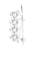
図1は、本発明の第1の実施の形態におけるカラー画像形成装置の概略構成を示す断面図である。本装置は電子写真プロセスを用いた画像形成装置である。
(First embodiment)
FIG. 1 is a cross-sectional view showing a schematic configuration of a color image forming apparatus according to a first embodiment of the present invention. This apparatus is an image forming apparatus using an electrophotographic process.
同図において、1a〜1dは感光体、2a〜2dは1次帯電部、3a〜3dは露光部、4a〜4dは現像部、53a〜53dは1次転写部、6a〜6dはクリーナー、51は中間転写ベルト、55は中間転写ベルトクリーナー、56、57は2次転写部である。各1次帯電部によって各感光体が一様に帯電された後、画像信号に応じて変調されたレーザ光が各露光部によって各感光体に照射されることにより、各感光体上に静電潜像が形成される。その後、現像手段によってトナー像が現像され、4個の感光体上のトナー像は転写部によって中間転写ベルト51に重ねて転写され、更に2次転写部によって記録紙Pに転写される。各感光体上に残った転写残トナーはクリーナーによって回収される。また、中間転写ベルト51上に残った転写残トナーは中間転写ベルトクリーナー55によって回収される。記録紙Pに転写されたトナー像は定着器7によって定着されることにより、カラー画像を得る。定着器7の構成としては、電磁誘導加熱方式を用いている。
In the figure, reference numerals 1a to 1d are photosensitive members, 2a to 2d are primary charging units, 3a to 3d are exposure units, 4a to 4d are development units, 53a to 53d are primary transfer units, 6a to 6d are cleaners, 51 Is an intermediate transfer belt, 55 is an intermediate transfer belt cleaner, and 56 and 57 are secondary transfer portions. After each photoconductor is uniformly charged by each primary charging unit, each photoconductor is irradiated with a laser beam modulated in accordance with an image signal. A latent image is formed. Thereafter, the toner images are developed by the developing means, and the toner images on the four photoconductors are transferred onto the
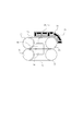
図2は電磁誘導加熱方式を用いた定着器の断面構成図である。図中72、75は定着ベルトであり、特にベルト72は導電性発熱体を含む加熱部材としての金属ベルトであり、その表面は300μmのゴム層で覆われている。ベルト72はローラ73、74を軸に、ベルト75はローラ76、77、を軸に図中矢印の方向に回転している。また、導電性発熱体であるベルト72に対向して誘導加熱コイル71がコイルホルダ70内に配置され、コイル71に交流電流を流して磁場を発生させることで、ベルト72の導電性発熱体が自己発熱する。78はサーミスタであり、ベルト72の奥行き方向の中央、奥、手前にサーミスタ78a、78b、78cがベルト72の内側から当接しており、ベルト72の温度を検出している。サーミスタ78は温度が低いほど高い抵抗値となる抵抗体である。本定着器は中央のサーミスタ78aで検知される温度を目標の温度である190℃になるようにコイル71に流す交流電流を増減させている。90と91はそれぞれ上パッド、下パッドで、その間には約40kg重の圧力がかかっている。
FIG. 2 is a cross-sectional configuration diagram of a fixing device using an electromagnetic induction heating method. In the figure,
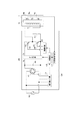
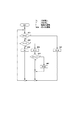
図3は誘導加熱方式を用いた定着器に給電する電源装置の構成を示すブロック図である。同図において、500は交流電源、100は電源装置、101は交流を整流するダイオードブリッジ101、102はフィルタコンデンサ102、105はコイル71とともに共振回路を形成する共振コンデンサである。108はダイオードブリッジ101で整流された直流電圧を昇圧回路であり、その昇圧比は可変であり、例えば1〜3の範囲で変化する。103,104はコイル71への電力を制御する第1、第2のスイッチ素子、112はスイッチ素子103,104を駆動信号121、122で駆動する駆動回路である。113は昇圧回路108及び駆動回路112を制御する制御部、111は交流電源500の入力電力を検出する電力検出回路である。78a〜78cはサーミスタである。114はサーミスタ78a〜78cからの信号に基づいてベルト72の温度を検出する温度検出回路である。制御部113は電力検出回路111の検出結果及び温度検出回路114の検出結果に基づいて、コイル71に供給すべき電力を決定し、決定した電力となるように駆動回路112が出力する駆動信号121、122の駆動周波数及び昇圧回路108の昇圧比を決定する。スイッチ素子103と104は駆動信号121、122に従って交互にON/OFFし、コイル71に高周波電流を供給する。
FIG. 3 is a block diagram illustrating a configuration of a power supply device that supplies power to a fixing device using an induction heating method. In the figure, 500 is an AC power source, 100 is a power supply device, 101 is a
本構成においては昇圧回路108の昇圧比が1すなわちVo=Viで動作する電力範囲では周波数制御モードで動作し、この電力範囲より高い電力範囲では電圧制御モードで動作する。
In this configuration, the
図4は駆動回路112から出力されるスイッチ素子103,104の駆動信号121、122の周波数とコイル71に供給される電力との関係を表した図である。
FIG. 4 is a diagram showing the relationship between the frequency of the drive signals 121 and 122 of the switch elements 103 and 104 output from the
昇圧回路108の昇圧比を1に固定、すなわちVo=Viの場合の特性曲線では、駆動信号の周波数fが共振周波数f1の時に電力P=Pr(基準電力)となり、更に駆動信号の周波数fをf1より高いf2にすると、基準電力Prよりも電力の低いP4となる。更に駆動信号の周波数を高くすればする程電力Pを下げることができる。電力をPrよりも高くしたい場合は、駆動信号の周波数fをf1に固定したまま昇圧回路108の昇圧比を上げる、即ち、Vo=V3、V2、V1(V3<V2<V1)とすることでコイル71に供給する電力もP3、P2、P1と高くすることができる。図5は、駆動信号121、122の周波数fが共振周波数f1の時の昇圧回路108の出力電圧Voと電力Pの関係を示した図である。
In the characteristic curve when the boosting ratio of the
このように本実施の形態では、周波数制御モードと電圧制御モードとの2つの電力制御モードを有し、選択的に実行している。即ち、周波数制御モードは、昇圧回路108の昇圧比を所定昇圧比に固定させてスイッチ素子の駆動周波数を所定周波数以上の範囲で変化させて供給電力を制御するモード(第1の制御モード)である。また、電圧制御モードは、スイッチ素子の駆動周波数を所定周波数に固定させて昇圧回路108の昇圧比を所定昇圧比以上の範囲で変化させて供給電力を制御するモード(第2の制御モード)である。
As described above, the present embodiment has two power control modes, the frequency control mode and the voltage control mode, and is selectively executed. That is, the frequency control mode is a mode (first control mode) in which the boosting ratio of the
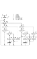
図6は、制御部113による定着器の電力制御のフローチャートである。なお、本実施の形態では、サーミスタ78aが設置されたベルト72の中央部の温度Tを目標温度Toに制御するものとして説明する。
FIG. 6 is a flowchart of the power control of the fixing device by the
制御部113は、まず動作開始時に電力制御のモードを周波数制御モードに初期設定する(ステップ999)。周波数制御モードに初期設定する理由は、制御開始時にベルト72の温度を高くするように低電力状態から徐々に電力を上げていくためである。ステップ1000において、制御部113は現在の制御モードが電圧制御モードであるか否かを判断し、周波数制御モードであると判断すると、ステップ1001、1002においてサーミスタ78aの出力に基づく検出温度Tと目標温度Toとを比較する。T>Toの場合、制御部113はベルト72の温度を低下させるべく、ステップ1007において周波数を所定量fbだけ高くし、ステップ1000へ戻る。T<Toの場合、ベルト72の温度を高くする必要がある。制御部113は、ステップ1003において周波数を所定量faだけ低くした値が共振周波数f1よりも高いか否か、即ち、f−fa≧f1を満たすか否か判断する。f−fa≧f1である場合、制御部113はステップ1006において周波数を所定の値faだけ低くし、ステップ1000へ戻る。f−fa≧f1でない場合、制御部113はステップ1005において周波数をf1に設定し、ステップ1008において、電力制御モードを周波数制御モードから電圧制御モードに切り換え、ステップ1000へ戻る。ステップ1001,1002において、T=Toの場合は制御部113は周波数fを維持する。
First, the
制御部113は、ステップ1000において現在の電力制御モードが電圧制御モードであると判断した場合、ステップ1011、1012においてサーミスタ78aの出力に基づく検出温度Tと目標温度Toとを比較する。T<Toの場合、ベルト72の温度を高くする必要がある。制御部113は、ステップ1017においてコイル71への供給電力Pが上限電力Pmax未満か否かを判断する。P<Pmaxでない場合、制御部113は昇圧回路108の出力電圧Voをそのまま維持し、ステップ1000へ戻る。P<Pmaxの場合、制御部113はステップ1019において昇圧回路108の出力電圧Voを所定の値Vbだけ高くするよう昇圧比を設定し、ステップ1000へ戻る。T>Toの場合、制御部113はステップ1013において昇圧回路108の出力電圧Voを所定の値Vaだけ低くすると昇圧回路108の入力電圧Viよりも低くなるか否か、即ち、Vo−Va<Viを満たすか否かを判断する。Vo−Va<Viである場合、制御部113はステップ1016において昇圧回路108の出力電圧Voを所定の値Vaだけ低くするよう昇圧非を設定し、ステップ1000へ戻る。Vo−Va<Viでない場合、制御部113はステップ1015においてVo=Vi(昇圧比を1)とした後さらにステップ1018において電力制御モードを電圧制御モードから周波数制御モードに切り換え、ステップ1000へ戻る。T=Toの場合、制御部113は昇圧回路108の出力電圧Voをそのまま維持し、ステップ1000へ戻る。
When the
例えば、電源装置100から見た定着器7のインダクタンスが40μH、共振コンデンサ105の容量が1μFとすると、共振周波数f1は約25kHzとなる。商用電源500の電圧が100Vの場合、Viは約140Vとなり、本実施の形態の構成においては、この時のPrは500Wとなっている。つまり、500Wより大電力領域では駆動周波数25kHz一定の電圧制御モードで動作し、500Wより小電力領域では昇圧回路108の出力電圧140V一定の周波数制御モード(駆動周波数25kHz以上)で動作する。
For example, when the inductance of the fixing
以上説明したように、高効率が求められる大電力領域ではスイッチ素子を共振周波数で駆動したまま昇圧比を変化させることでスイッチ素子の損失を軽減することが可能となる。また、小電力領域ではスイッチ素子の駆動周波数を変化させることで、降圧回路を必要とせずに電力制御が可能となる。 As described above, in a high power region where high efficiency is required, it is possible to reduce the loss of the switch element by changing the step-up ratio while driving the switch element at the resonance frequency. In the low power region, by changing the drive frequency of the switch element, power control can be performed without the need for a step-down circuit.
(第2の実施の形態)
第2の実施の形態における画像形成装置及び電源装置の構成としては、第1の実施の形態と同様である。図7は第2の実施の形態における電力制御のフローチャートである。第2の実施形態でも、サーミスタ78aが設置されたベルト72の中央部の温度Tを目標温度Toに制御するものとして説明する。
(Second Embodiment)
The configurations of the image forming apparatus and the power supply apparatus in the second embodiment are the same as those in the first embodiment. FIG. 7 is a flowchart of power control in the second embodiment. In the second embodiment, the temperature T at the center of the
まず、ステップ1997にて、制御部113は商用電源500の電圧を検出し、ステップ1998で、電圧制御モードと周波数制御モードとを切り換える基準となる電力Pa及びPbを電圧検出値に応じて設定する。即ち、電力Paは、昇圧回路108の昇圧比を所定昇圧比としスイッチ素子の駆動周波数を所定周波数としたときの電力Prよりも小さい第1の所定の電力となる。電力Pbは、昇圧回路108の昇圧比を所定昇圧比としスイッチ素子の駆動周波数を所定周波数としたときの電力Prよりも大きい第2の所定の電力となる。なおPa、Pb、Prの関係は図8に示すようにPa<Pr<Pbである。次にステップ1999において、制御部113は電力制御モードを周波数制御モードに初期設定する。周波数制御モードに初期設定する理由は、制御開始時に低電力から徐々に電力を上げていくためである。制御部113は、ステップ2000において、現在の電力制御モードが電圧制御モードか否かを判断し、電圧制御モードではなく周波数制御モードであると判断すると、ステップ2001、2002において検出温度Tと目標温度Toとを比較する。T>Toの場合、制御部113はステップ2007において、周波数を所定の値fbだけ高くし、ステップ2000へ戻る。T<Toの場合、制御部113はステップ2003においてコイル71への供給電力Pと設定値Paとを比較し、P<Paの場合はステップ2006において周波数を所定の値faだけ低くし、ステップ2000へ戻る。P≧Paの場合、制御部113はステップ2005において周波数をf=f1とし、ステップ2008で電力制御モードを電圧制御モードに切り換える。ステップ2002において、T<Toでない場合、即ち、T=Toの場合、制御部113は周波数fをそのまま維持し、ステップ2000へ戻る。
First, in
一方、ステップ2000において現在の電力制御モードが電圧制御モードであると判断された場合、制御部113は、ステップ2011、2012において検出温度Tと目標温度Toを比較する。T<Toの場合、制御部113はステップ2017において電力Pが上限電力Pmax未満か否かを判断し、P<Pmaxでない場合、昇圧回路108の出力電圧Voを維持し、ステップ2000へ戻る。P<Pmaxの場合は、制御部113はステップ2019において昇圧回路108の出力電圧Voを所定の値Vbだけ高くし、ステップ2000へ戻る。T>Toの場合、制御部113はステップ2013において電力Pと設定値Pbとを比較し、P>Pbの場合はステップ2016において昇圧回路108の出力電圧Voを所定の値Vaだけ低くし、ステップ2000へ戻る。P≦Pbの場合、制御部113はステップ2015においてVo=Viとし、ステップ2018において電力制御モードを周波数制御モードに切り換える。ステップ2012でT>Toでない場合、即ちT=Toの場合、制御部113は昇圧回路108の出力電圧Voを維持し、ステップ2000へ戻る。
On the other hand, when it is determined in
例えば、電源装置100から見た定着器7のインダクタンスが40μH、共振コンデンサ105の容量が1μFとすると、共振周波数f1は約25kHzとなる。商用電源500の電圧が100Vの場合、Viは約140Vとなり、本実施形態の定着器7の構成においては、この時のPrは500Wとなっている。この時Paは470W、Pbは530Wに設定する。
For example, when the inductance of the fixing
また、商用電源500の電圧が120Vの場合はPrは720Wとなっている。この時Paは690W、Pbは750Wに設定する。
When the voltage of the
(第3の実施の形態)
本発明の第3の実施の形態である画像形成装置及び電源装置の構成としては、第1及び第2の実施の形態と同様である。
(Third embodiment)
The configurations of the image forming apparatus and the power supply apparatus according to the third embodiment of the present invention are the same as those in the first and second embodiments.
第3の実施の形態では、制御部113が図10に示すような入力電力Pに対応させて、昇圧回路108の出力電圧Voと駆動周波数fの関係を表わすデータを記憶したテーブルを持っている。制御部113は、定着部7の目標温度と検出温度との差分に応じてテーブルのデータ番号で示される出力電圧Vo(昇圧比)と駆動周波数fを選択する。図9のテーブルの関係をグラフで表すと図10のようになる。
In the third embodiment, the
テーブルのデータ番号が1から3、すなわち電力P1からP3では駆動周波数をf=f1に固定してVoを変化させる電圧制御モードで制御される。データ番号=4、すなわち電力Prでは駆動周波数をf=f1、Vo=Viに固定される。データ番号が5から7、すなわち電力P5からP7では、Vo=Viに固定して駆動周波数fを変化させる周波数制御モードで制御される。即ち、電力Prを境にして、Prよりも大きい電力を必要とする場合は電圧制御モードが選択され、Prよりも小さい電力を必要とする場合は周波数制御モードが選択される。なお、本例ではVoとfの組合わせを8種類としたが、データ番号1と8の間をもっと多くしてもよい。
When the data number of the table is 1 to 3, that is, the powers P1 to P3, the voltage is controlled in the voltage control mode in which the driving frequency is fixed to f = f1 and Vo is changed. When the data number is 4, that is, the power Pr, the drive frequency is fixed to f = f1 and Vo = Vi. When the data number is 5 to 7, that is, the powers P5 to P7, control is performed in a frequency control mode in which the drive frequency f is changed while fixing Vo = Vi. That is, with the electric power Pr as a boundary, the voltage control mode is selected when electric power larger than Pr is required, and the frequency control mode is selected when electric power smaller than Pr is required. In this example, there are eight combinations of Vo and f, but the number between
図11は、第3の実施の形態における電力制御のフローチャートである。第3の実施の形態においてもサーミスタ78aが設置された導電性発熱体72の中央部の温度Tを目標温度Toに制御するものとして説明する。
FIG. 11 is a flowchart of power control in the third embodiment. Also in the third embodiment, description will be made assuming that the temperature T at the center of the
制御が開始されると、制御部113は、ステップ2997にて商用電源500の電圧を検出し、表1に示すような昇圧回路の出力電圧Voと駆動周波数fの組み合わせのテーブルを前記電圧検出値に応じてステップ2998で設定する。具体的には、商用交流電源が100V系か200V系かを判断し、100V系であれば100V用のテーブルを設定し、200V系であれば200V用のテーブルを設定する。なお、画像形成装置が設置される国、地域により別のテーブルを設定してもよい。次にステップ2999において昇圧回路の出力電圧Voと駆動周波数fの組み合わせが停止状態であるデータ番号=8に設定される。制御部113は、ステップ3000において検出温度Tと目標温度Toとを比較し、T>Toの場合はステップ3006においてその時点で設定されているデータ番号(以降、現在のデータ番号と称す)Xが8、つまり停止状態かどうかを判断する。データ番号Xが8ならば制御部113は、データ番号Xをそのまま維持し、ステップ3000へ戻る。ステップ3006で、データ番号Xが8でなければ、制御部113は、ステップ3007へ進み、誘導加熱コイル71に供給すべき電力を減少させるべく、現在のデータ番号Xよりも一つ上の番号で設定されているVoとfの組み合わせに変化させる。従って、定着器7が目標温度を超えている場合は、ステップ3000,3006,3007,3000,・・・の繰り返しによりデータ番号Xが順次増えていき、X=8となることもある。
When the control is started, the
ステップ3000でT>Toでない場合はステップ3001へ進む。ステップ3001でT<Toの場合、制御部113は、ステップ3002において現在のデータ番号Xが1、つまり最大電力設定かどうかを判断し、データ番号Xが1ならばデータ番号をそのまま維持し、ステップ3000へ戻る。ステップ3002でデータ番号Xが1でなければ、制御部113は、誘導加熱コイル71に供給すべき電力を増加させるべく、ステップ3004へ進み現在のデータ番号Xよりも一つ下の番号で設定されているVoとfの組み合わせに変化させる。従って、電源オン時等の定着器7が冷えている場合は、ステップ3000,3001,3002,3004,3000,・・・の繰り返しにより、データ番号Xが順次減っていき、X=1になることもある。ステップ3001でT<Toでない場合、制御113はデータ番号Xをそのまま維持し、ステップ3000へ戻る。
If T> To is not satisfied in
以上説明したように、高効率が求められる大電力領域ではスイッチ素子を共振周波数で駆動したまま昇圧比を変化させることでスイッチ素子の損失を軽減することが可能となる。また、小電力領域ではスイッチ素子の駆動周波数を変化させることで、降圧回路を必要とせずに電力制御が可能となる。 As described above, in a high power region where high efficiency is required, it is possible to reduce the loss of the switch element by changing the step-up ratio while driving the switch element at the resonance frequency. In the low power region, by changing the drive frequency of the switch element, power control can be performed without the need for a step-down circuit.
7 定着器
71 コイル
72 ベルト
78 温度検出素子
108 昇圧回路
112 駆動回路
113 制御部
114 温度検出回路
7 Fixing
Claims (6)
導電性発熱体を含む加熱部材を加熱するための誘導加熱コイルと、
交流電源を整流して得られる直流電圧を昇圧する昇圧回路と、
前記昇圧回路の出力が供給され、前記誘導加熱コイルに高周波電流を供給するスイッチ素子と、
前記スイッチ素子を駆動する駆動回路と、
前記加熱部材の温度を検出する温度検出手段と、
前記温度検出手段により検出された温度が目標温度となるように前記昇圧回路の昇圧比と前記駆動回路による前記スイッチ素子の駆動周波数を制御することにより前記誘導加熱コイルへ供給する電力を制御する制御部と、
を有し、前記制御部は、前記昇圧回路の昇圧比を前記所定昇圧比に固定した状態で所定周波数以上の範囲で前記スイッチ素子の駆動周波数を変化させる第1の制御モードと、前記スイッチ素子の駆動周波数を前記所定周波数に固定した状態で前記昇圧回路の昇圧比を所定昇圧比以上の範囲で変化させる第2の制御モードとを選択的に実行するものであり、
前記制御部は、前記第1の制御モードが選択されている状態で、前記温度検出手段により検出された温度が前記目標温度よりも低い場合、該温度が検出された時に設定されている駆動周波数を所定量低くした値が前記所定周波数より低くなるならば、前記第1の制御モードから第2の制御モードへ切り換え、前記第2の制御モードが選択されている状態で、前記温度検出手段により検出された温度が前記目標温度よりも高い場合、該温度が検出された時に設定されている昇圧比を所定量小さくした値が前記所定昇圧比よりも小さくなるならば、前記第2の制御モードから第1の制御モードへ切り換えることを特徴とする定着装置。 A fixing device that performs heating by induction heating,
An induction heating coil for heating a heating member including a conductive heating element;
A booster circuit that boosts a DC voltage obtained by rectifying an AC power supply;
A switch element that is supplied with an output of the booster circuit and supplies a high-frequency current to the induction heating coil;
A drive circuit for driving the switch element;
Temperature detecting means for detecting the temperature of the heating member;
Control for controlling the power supplied to the induction heating coil by controlling the boost ratio of the boost circuit and the drive frequency of the switch element by the drive circuit so that the temperature detected by the temperature detection means becomes the target temperature. And
The control unit includes a first control mode for changing a drive frequency of the switch element in a range equal to or higher than a predetermined frequency in a state where the boost ratio of the booster circuit is fixed to the predetermined boost ratio, and the switch element And a second control mode in which the boosting ratio of the booster circuit is changed in a range equal to or higher than the predetermined boosting ratio while the driving frequency is fixed at the predetermined frequency .
When the temperature detected by the temperature detection unit is lower than the target temperature in a state where the first control mode is selected, the control unit sets a drive frequency set when the temperature is detected. If the value obtained by lowering the value by a predetermined amount becomes lower than the predetermined frequency, the temperature detection means switches from the first control mode to the second control mode and the second control mode is selected. If the detected temperature is higher than the target temperature, the second control mode is set if a value obtained by reducing the step-up ratio set when the temperature is detected by a predetermined amount is smaller than the predetermined step-up ratio. The fixing device is switched from the first control mode to the first control mode .
導電性発熱体を含む加熱部材を加熱するための誘導加熱コイルと、
交流電源を整流して得られる直流電圧を昇圧する昇圧回路と、
前記昇圧回路の出力が供給され、前記誘導加熱コイルに高周波電流を供給するスイッチ素子と、
前記スイッチ素子を駆動する駆動回路と、
前記加熱部材の温度を検出する温度検出手段と、
前記温度検出手段により検出された温度が目標温度となるように前記昇圧回路の昇圧比と前記駆動回路による前記スイッチ素子の駆動周波数を制御することにより前記誘導加熱コイルへ供給する電力を制御する制御部と、
を有し、前記制御部は、前記昇圧回路の昇圧比を前記所定昇圧比に固定した状態で所定周波数以上の範囲で前記スイッチ素子の駆動周波数を変化させる第1の制御モードと、前記スイッチ素子の駆動周波数を前記所定周波数に固定した状態で前記昇圧回路の昇圧比を所定昇圧比以上の範囲で変化させる第2の制御モードとを選択的に実行するものであり、
前記制御部は、前記第1の制御モードが選択されている状態で、前記温度検出手段により検出された温度が前記目標温度よりも低い場合で且つ、前記誘導加熱コイルへ供給すべき電力を、前記昇圧比が前記所定昇圧比であり、前記駆動周波数が記所定周波数であるときの電力よりも小さい第1の所定の電力よりも高くする場合に、前記第1の制御モードから第2の制御モードへ切り換え、前記第2の制御モードが選択されている状態で、前記温度検出手段により検出された温度が前記目標温度よりも高い場合で且つ、前記誘導加熱コイルへ供給すべき電力を、前記昇圧比が前記所定昇圧比であり前記駆動周波数が前記所定周波数であるときの電力よりも大きい第2の所定の電力よりも低くする場合、前記第2の制御モードから第1の制御モードへ切り換えることを特徴とする定着装置。 A fixing device that performs heating by induction heating,
An induction heating coil for heating a heating member including a conductive heating element;
A booster circuit that boosts a DC voltage obtained by rectifying an AC power supply;
A switch element that is supplied with an output of the booster circuit and supplies a high-frequency current to the induction heating coil;
A drive circuit for driving the switch element;
Temperature detecting means for detecting the temperature of the heating member;
Control for controlling the power supplied to the induction heating coil by controlling the boost ratio of the boost circuit and the drive frequency of the switch element by the drive circuit so that the temperature detected by the temperature detection means becomes the target temperature. And
The control unit includes a first control mode for changing a drive frequency of the switch element in a range equal to or higher than a predetermined frequency in a state where the boost ratio of the booster circuit is fixed to the predetermined boost ratio, and the switch element And a second control mode in which the boosting ratio of the booster circuit is changed in a range equal to or higher than the predetermined boosting ratio while the driving frequency is fixed at the predetermined frequency.
When the temperature detected by the temperature detection means is lower than the target temperature in the state where the first control mode is selected, the control unit supplies power to be supplied to the induction heating coil. before a KiNoboru pressure ratio the predetermined boost ratio, if the previous hear dynamic frequency is higher than the first predetermined power lower than the power when the serial is a predetermined frequency, before Symbol first control mode Switch to the second control mode, and when the second control mode is selected, the temperature detected by the temperature detecting means is higher than the target temperature and should be supplied to the induction heating coil When the power is set to be lower than a second predetermined power that is higher than the power when the boost ratio is the predetermined boost ratio and the drive frequency is the predetermined frequency, the first control mode starts from the second control mode. Control mode Constant Chakusochi characterized the switch between the to.
導電性発熱体を含む加熱部材を加熱するための誘導加熱コイルと、
交流電源を整流して得られる直流電圧を昇圧する昇圧回路と、
前記昇圧回路の出力が供給され、前記誘導加熱コイルに高周波電流を供給するスイッチ素子と、
前記スイッチ素子を駆動する駆動回路と、
前記加熱部材の温度を検出する温度検出手段と、
前記温度検出手段により検出された温度が目標温度となるように前記昇圧回路の昇圧比と前記駆動回路による前記スイッチ素子の駆動周波数を制御することにより前記誘導加熱コイルへ供給する電力を制御する制御部と、
を有し、前記制御部は、前記昇圧回路の昇圧比を前記所定昇圧比に固定した状態で所定周波数以上の範囲で前記スイッチ素子の駆動周波数を変化させる第1の制御モードと、前記スイッチ素子の駆動周波数を前記所定周波数に固定した状態で前記昇圧回路の昇圧比を所定昇圧比以上の範囲で変化させる第2の制御モードとを選択的に実行するものであり、
前記制御部は、前記温度検出手段により検出された温度が前記目標温度よりも低い場合、前記誘導加熱コイルに供給すべき電力を増加させ、前記温度検出手段により検出された温度が前記目標温度よりも高い場合、前記誘導加熱コイルに供給すべき電力を減少させるものであり、且つ前記供給すべき電力が、前記昇圧比を前記所定昇圧比とし前記駆動周波数を前記所定周波数としたときの所定の電力より小さければ、前記第1の制御モードを選択し、前記供給すべき電力が前記所定の電力より大きければ、前記第2の制御モードを選択することを特徴とする定着装置。 A fixing device that performs heating by induction heating,
An induction heating coil for heating a heating member including a conductive heating element;
A booster circuit that boosts a DC voltage obtained by rectifying an AC power supply;
A switch element that is supplied with an output of the booster circuit and supplies a high-frequency current to the induction heating coil;
A drive circuit for driving the switch element;
Temperature detecting means for detecting the temperature of the heating member;
Control for controlling the power supplied to the induction heating coil by controlling the boost ratio of the boost circuit and the drive frequency of the switch element by the drive circuit so that the temperature detected by the temperature detection means becomes the target temperature. And
The control unit includes a first control mode for changing a drive frequency of the switch element in a range equal to or higher than a predetermined frequency in a state where the boost ratio of the booster circuit is fixed to the predetermined boost ratio, and the switch element And a second control mode in which the boosting ratio of the booster circuit is changed in a range equal to or higher than the predetermined boosting ratio while the driving frequency is fixed at the predetermined frequency.
When the temperature detected by the temperature detection unit is lower than the target temperature, the control unit increases the electric power to be supplied to the induction heating coil, and the temperature detected by the temperature detection unit is higher than the target temperature. Is higher, the power to be supplied to the induction heating coil is reduced, and the power to be supplied is a predetermined value when the boost ratio is the predetermined boost ratio and the drive frequency is the predetermined frequency . smaller than the power, the first to select the control mode, if the power to be the supply is greater than the predetermined power, the constant you and selects the second control mode Chakusochi.
Priority Applications (7)
| Application Number | Priority Date | Filing Date | Title |
|---|---|---|---|
| JP2008288944A JP5317633B2 (en) | 2008-11-11 | 2008-11-11 | Fixing device |
| KR1020090107478A KR101438847B1 (en) | 2008-11-11 | 2009-11-09 | Power supply circuitry for inductive heating element |
| RU2009141638/07A RU2404550C1 (en) | 2008-11-11 | 2009-11-10 | Power supply circuit for induction heating element |
| US12/615,879 US8461497B2 (en) | 2008-11-11 | 2009-11-10 | Power supply circuitry for inductive heating element and capable of minimizing losses to switching element |
| EP09175691A EP2184651A2 (en) | 2008-11-11 | 2009-11-11 | Power supply circuitry for inductive heating element |
| CN2009102216508A CN101738915B (en) | 2008-11-11 | 2009-11-11 | Fixing device andPower supply circuitry for inductive heating element |
| US13/894,795 US8768192B2 (en) | 2008-11-11 | 2013-05-15 | Fixing apparatus of induction heating type for fixing image formed on sheet |
Applications Claiming Priority (1)
| Application Number | Priority Date | Filing Date | Title |
|---|---|---|---|
| JP2008288944A JP5317633B2 (en) | 2008-11-11 | 2008-11-11 | Fixing device |
Publications (3)
| Publication Number | Publication Date |
|---|---|
| JP2010117431A JP2010117431A (en) | 2010-05-27 |
| JP2010117431A5 JP2010117431A5 (en) | 2012-01-12 |
| JP5317633B2 true JP5317633B2 (en) | 2013-10-16 |
Family
ID=41720604
Family Applications (1)
| Application Number | Title | Priority Date | Filing Date |
|---|---|---|---|
| JP2008288944A Expired - Fee Related JP5317633B2 (en) | 2008-11-11 | 2008-11-11 | Fixing device |
Country Status (6)
| Country | Link |
|---|---|
| US (2) | US8461497B2 (en) |
| EP (1) | EP2184651A2 (en) |
| JP (1) | JP5317633B2 (en) |
| KR (1) | KR101438847B1 (en) |
| CN (1) | CN101738915B (en) |
| RU (1) | RU2404550C1 (en) |
Families Citing this family (8)
| Publication number | Priority date | Publication date | Assignee | Title |
|---|---|---|---|---|
| CN103548416B (en) * | 2011-03-30 | 2016-09-07 | Bsh家用电器有限公司 | Induction heating apparatus and operation method thereof and the home appliances of band induction heating apparatus |
| JP5375872B2 (en) * | 2011-04-27 | 2013-12-25 | コニカミノルタ株式会社 | Induction heating apparatus and image forming apparatus |
| JP2015014682A (en) | 2013-07-04 | 2015-01-22 | 株式会社リコー | Fixing device and image forming apparatus |
| JP5886251B2 (en) * | 2013-08-19 | 2016-03-16 | 京セラドキュメントソリューションズ株式会社 | Image forming apparatus and image forming method |
| AU2014346306B2 (en) * | 2013-11-08 | 2019-10-03 | Bank Of Canada | Optically variable devices, their production and use |
| CN105338674B (en) * | 2014-07-02 | 2019-04-30 | 浙江苏泊尔家电制造有限公司 | A kind of electric cooker of electromagnetic heating method and the electromagnetic heating using this method |
| JP6483399B2 (en) | 2014-10-23 | 2019-03-13 | エイチピー プリンティング コリア カンパニー リミテッド | Induction heating type image fixing apparatus and induction heating type image fixing apparatus driving program |
| CN104561470B (en) * | 2015-02-02 | 2017-02-15 | 扬中市盛达电器制造有限责任公司 | Parallel resonance intermediate-frequency welding heat treatment device |
Family Cites Families (13)
| Publication number | Priority date | Publication date | Assignee | Title |
|---|---|---|---|---|
| JP2000223253A (en) | 1999-01-29 | 2000-08-11 | Canon Inc | Heating device |
| JP2002124370A (en) * | 2000-10-13 | 2002-04-26 | Ricoh Co Ltd | Induction heating device, and image processing device provided with the induction heating device |
| US6930293B2 (en) * | 2002-02-04 | 2005-08-16 | Canon Kabushiki Kaisha | Induction heating apparatus, heat fixing apparatus and image forming apparatus |
| JP2004004205A (en) * | 2002-05-30 | 2004-01-08 | Canon Inc | Fixing device and image forming device |
| WO2004074944A1 (en) * | 2003-02-20 | 2004-09-02 | Matsushita Electric Industrial Co., Ltd. | Heating fixing device |
| ES2344063T3 (en) * | 2003-10-30 | 2010-08-17 | Panasonic Corporation | INDUCTION HEATING COOKING DEVICE. |
| JP4444076B2 (en) * | 2004-11-15 | 2010-03-31 | 株式会社東芝 | Induction heating cooker |
| CN101010989B (en) * | 2005-06-02 | 2011-05-11 | 松下电器产业株式会社 | Induction heating apparatus |
| DE602006016117D1 (en) * | 2005-06-02 | 2010-09-23 | Panasonic Corp | INDUCTION HEATER |
| JP4893120B2 (en) * | 2005-06-17 | 2012-03-07 | パナソニック株式会社 | Induction heating device |
| EP1838138B1 (en) * | 2006-03-20 | 2013-02-27 | Ricoh Company, Ltd. | Booster circuit for enhanced induction heating unit, power-supply unit, and image forming apparatus using the same |
| JP2007286495A (en) * | 2006-04-19 | 2007-11-01 | Canon Inc | Heating device and image forming apparatus |
| US9724777B2 (en) * | 2009-04-08 | 2017-08-08 | Hakko Corporation | System and method for induction heating of a soldering iron |
-
2008
- 2008-11-11 JP JP2008288944A patent/JP5317633B2/en not_active Expired - Fee Related
-
2009
- 2009-11-09 KR KR1020090107478A patent/KR101438847B1/en not_active IP Right Cessation
- 2009-11-10 US US12/615,879 patent/US8461497B2/en not_active Expired - Fee Related
- 2009-11-10 RU RU2009141638/07A patent/RU2404550C1/en not_active IP Right Cessation
- 2009-11-11 EP EP09175691A patent/EP2184651A2/en not_active Withdrawn
- 2009-11-11 CN CN2009102216508A patent/CN101738915B/en not_active Expired - Fee Related
-
2013
- 2013-05-15 US US13/894,795 patent/US8768192B2/en not_active Expired - Fee Related
Also Published As
| Publication number | Publication date |
|---|---|
| JP2010117431A (en) | 2010-05-27 |
| US20130251391A1 (en) | 2013-09-26 |
| CN101738915B (en) | 2012-05-30 |
| CN101738915A (en) | 2010-06-16 |
| RU2404550C1 (en) | 2010-11-20 |
| US8768192B2 (en) | 2014-07-01 |
| KR101438847B1 (en) | 2014-09-05 |
| EP2184651A2 (en) | 2010-05-12 |
| US20100119248A1 (en) | 2010-05-13 |
| US8461497B2 (en) | 2013-06-11 |
| KR20100053447A (en) | 2010-05-20 |
Similar Documents
| Publication | Publication Date | Title |
|---|---|---|
| JP5317633B2 (en) | Fixing device | |
| JP5019814B2 (en) | Image forming apparatus and power control method | |
| KR101375503B1 (en) | Induction heating circuit and image forming apparatus | |
| US7184697B2 (en) | Fixing apparatus having an induction heating control circuit | |
| JP6452105B2 (en) | Image forming apparatus | |
| JP2018155783A (en) | Image formation apparatus | |
| US20020148828A1 (en) | Induction heating apparatus for heating image formed on recording material | |
| JP2016136172A (en) | Heater control device and image formation device | |
| US9213280B2 (en) | Image-forming apparatus supplying power to heat generating member using phase control and/or wave number control | |
| JP5465082B2 (en) | Heating control apparatus and image forming apparatus | |
| JP2004004205A (en) | Fixing device and image forming device | |
| JP5219585B2 (en) | Image forming apparatus | |
| JP2008061352A (en) | Electric equipment and image forming device | |
| US9411279B2 (en) | Image forming and fixing apparatuses having fixing and pressing rotating member and rectification element | |
| JP4779573B2 (en) | Image forming apparatus | |
| JP2005003886A (en) | Image forming apparatus | |
| JP3718622B2 (en) | Induction heating device | |
| JP5308965B2 (en) | Power supply device and fixing device | |
| JP2007140329A (en) | Image forming apparatus and fixing device | |
| JP2003122183A (en) | Fixing device and image forming apparatus | |
| JP2011253196A (en) | Image forming apparatus | |
| JP4194530B2 (en) | Fixing device | |
| JP5577436B2 (en) | Power supply device and fixing device | |
| JP2002328553A (en) | Heating device and image forming device | |
| JP6362491B2 (en) | Fixing device |
Legal Events
| Date | Code | Title | Description |
|---|---|---|---|
| RD01 | Notification of change of attorney |
Free format text: JAPANESE INTERMEDIATE CODE: A7421 Effective date: 20100630 |
|
| A521 | Request for written amendment filed |
Free format text: JAPANESE INTERMEDIATE CODE: A523 Effective date: 20111111 |
|
| A621 | Written request for application examination |
Free format text: JAPANESE INTERMEDIATE CODE: A621 Effective date: 20111111 |
|
| A521 | Request for written amendment filed |
Free format text: JAPANESE INTERMEDIATE CODE: A523 Effective date: 20111117 |
|
| A977 | Report on retrieval |
Free format text: JAPANESE INTERMEDIATE CODE: A971007 Effective date: 20130130 |
|
| A131 | Notification of reasons for refusal |
Free format text: JAPANESE INTERMEDIATE CODE: A131 Effective date: 20130212 |
|
| A521 | Request for written amendment filed |
Free format text: JAPANESE INTERMEDIATE CODE: A523 Effective date: 20130415 |
|
| TRDD | Decision of grant or rejection written | ||
| A01 | Written decision to grant a patent or to grant a registration (utility model) |
Free format text: JAPANESE INTERMEDIATE CODE: A01 Effective date: 20130611 |
|
| A61 | First payment of annual fees (during grant procedure) |
Free format text: JAPANESE INTERMEDIATE CODE: A61 Effective date: 20130709 |
|
| LAPS | Cancellation because of no payment of annual fees |