JP5465082B2 - Heating control apparatus and image forming apparatus - Google Patents
Heating control apparatus and image forming apparatus Download PDFInfo
- Publication number
- JP5465082B2 JP5465082B2 JP2010106403A JP2010106403A JP5465082B2 JP 5465082 B2 JP5465082 B2 JP 5465082B2 JP 2010106403 A JP2010106403 A JP 2010106403A JP 2010106403 A JP2010106403 A JP 2010106403A JP 5465082 B2 JP5465082 B2 JP 5465082B2
- Authority
- JP
- Japan
- Prior art keywords
- power
- value
- abnormality
- power supply
- abnormality detection
- Prior art date
- Legal status (The legal status is an assumption and is not a legal conclusion. Google has not performed a legal analysis and makes no representation as to the accuracy of the status listed.)
- Expired - Fee Related
Links
Images


Classifications
-
- G—PHYSICS
- G03—PHOTOGRAPHY; CINEMATOGRAPHY; ANALOGOUS TECHNIQUES USING WAVES OTHER THAN OPTICAL WAVES; ELECTROGRAPHY; HOLOGRAPHY
- G03G—ELECTROGRAPHY; ELECTROPHOTOGRAPHY; MAGNETOGRAPHY
- G03G15/00—Apparatus for electrographic processes using a charge pattern
- G03G15/50—Machine control of apparatus for electrographic processes using a charge pattern, e.g. regulating differents parts of the machine, multimode copiers, microprocessor control
- G03G15/5012—Priority interrupt; Job recovery, e.g. after jamming or malfunction
-
- G—PHYSICS
- G03—PHOTOGRAPHY; CINEMATOGRAPHY; ANALOGOUS TECHNIQUES USING WAVES OTHER THAN OPTICAL WAVES; ELECTROGRAPHY; HOLOGRAPHY
- G03G—ELECTROGRAPHY; ELECTROPHOTOGRAPHY; MAGNETOGRAPHY
- G03G15/00—Apparatus for electrographic processes using a charge pattern
- G03G15/20—Apparatus for electrographic processes using a charge pattern for fixing, e.g. by using heat
- G03G15/2003—Apparatus for electrographic processes using a charge pattern for fixing, e.g. by using heat using heat
- G03G15/2014—Apparatus for electrographic processes using a charge pattern for fixing, e.g. by using heat using heat using contact heat
- G03G15/2039—Apparatus for electrographic processes using a charge pattern for fixing, e.g. by using heat using heat using contact heat with means for controlling the fixing temperature
- G03G15/205—Apparatus for electrographic processes using a charge pattern for fixing, e.g. by using heat using heat using contact heat with means for controlling the fixing temperature specially for the mode of operation, e.g. standby, warming-up, error
-
- G—PHYSICS
- G03—PHOTOGRAPHY; CINEMATOGRAPHY; ANALOGOUS TECHNIQUES USING WAVES OTHER THAN OPTICAL WAVES; ELECTROGRAPHY; HOLOGRAPHY
- G03G—ELECTROGRAPHY; ELECTROPHOTOGRAPHY; MAGNETOGRAPHY
- G03G15/00—Apparatus for electrographic processes using a charge pattern
- G03G15/20—Apparatus for electrographic processes using a charge pattern for fixing, e.g. by using heat
- G03G15/2003—Apparatus for electrographic processes using a charge pattern for fixing, e.g. by using heat using heat
- G03G15/2014—Apparatus for electrographic processes using a charge pattern for fixing, e.g. by using heat using heat using contact heat
- G03G15/2039—Apparatus for electrographic processes using a charge pattern for fixing, e.g. by using heat using heat using contact heat with means for controlling the fixing temperature
-
- G—PHYSICS
- G03—PHOTOGRAPHY; CINEMATOGRAPHY; ANALOGOUS TECHNIQUES USING WAVES OTHER THAN OPTICAL WAVES; ELECTROGRAPHY; HOLOGRAPHY
- G03G—ELECTROGRAPHY; ELECTROPHOTOGRAPHY; MAGNETOGRAPHY
- G03G15/00—Apparatus for electrographic processes using a charge pattern
- G03G15/50—Machine control of apparatus for electrographic processes using a charge pattern, e.g. regulating differents parts of the machine, multimode copiers, microprocessor control
- G03G15/5004—Power supply control, e.g. power-saving mode, automatic power turn-off
-
- G—PHYSICS
- G03—PHOTOGRAPHY; CINEMATOGRAPHY; ANALOGOUS TECHNIQUES USING WAVES OTHER THAN OPTICAL WAVES; ELECTROGRAPHY; HOLOGRAPHY
- G03G—ELECTROGRAPHY; ELECTROPHOTOGRAPHY; MAGNETOGRAPHY
- G03G2215/00—Apparatus for electrophotographic processes
- G03G2215/20—Details of the fixing device or porcess
- G03G2215/2003—Structural features of the fixing device
- G03G2215/2009—Pressure belt
-
- G—PHYSICS
- G03—PHOTOGRAPHY; CINEMATOGRAPHY; ANALOGOUS TECHNIQUES USING WAVES OTHER THAN OPTICAL WAVES; ELECTROGRAPHY; HOLOGRAPHY
- G03G—ELECTROGRAPHY; ELECTROPHOTOGRAPHY; MAGNETOGRAPHY
- G03G2215/00—Apparatus for electrophotographic processes
- G03G2215/20—Details of the fixing device or porcess
- G03G2215/2003—Structural features of the fixing device
- G03G2215/2016—Heating belt
- G03G2215/2025—Heating belt the fixing nip having a rotating belt support member opposing a pressure member
- G03G2215/2032—Heating belt the fixing nip having a rotating belt support member opposing a pressure member the belt further entrained around additional rotating belt support members
Description
本発明は、被加熱物を電磁誘導加熱によって加熱制御しつつ、当該被加熱物の異常を検知する加熱制御装置及び画像形成装置に関する。 The present invention relates to a heating control device and an image forming apparatus that detect an abnormality of a heated object while heating the heated object by electromagnetic induction heating.
一般に、被加熱物を電磁誘導加熱する際には、電磁誘導コイル(以下、単にコイルと呼ぶ)に高周波電力を印加して、これによって、コイルから発生する交番磁界によって被加熱物に生じる渦電流により、被加熱物を加熱している。 In general, when electromagnetically heating an object to be heated, high frequency power is applied to an electromagnetic induction coil (hereinafter simply referred to as a coil), and thereby an eddy current generated in the object to be heated by an alternating magnetic field generated from the coil. Thus, the object to be heated is heated.
ところで、電子写真プロセスを用いた複写機又はプリンター等の画像形成装置では、記録用紙等の記録材に担持された未定着画像(例えば、未定着トナー像)を定着する必要がある。このため、この画像形成装置においては、定着装置が用いられている。この定着装置において、記録材上の未定着画像を加熱・溶解して定着するようにしたものがある。 Incidentally, in an image forming apparatus such as a copying machine or a printer using an electrophotographic process, it is necessary to fix an unfixed image (for example, an unfixed toner image) carried on a recording material such as a recording sheet. For this reason, a fixing device is used in this image forming apparatus. In this fixing device, an unfixed image on a recording material is fixed by heating and melting.
なお、この種の定着装置として、記録材上の未定着画像を定着する定着装置ばかりでなく、例えば、記録材上に定着された画像を加熱して、画像の光沢を増大させる所謂光沢増大装置等も含まれる。 As this type of fixing device, not only a fixing device that fixes an unfixed image on a recording material but also a so-called gloss increasing device that increases the gloss of an image by heating an image fixed on the recording material, for example. Etc. are also included.
このように加熱によって未定着画像の定着を行う定着装置として、例えば、セラミックヒーターを用いた定着装置、ハロゲンヒーターを用いた定着装置、さらには、電磁誘導加熱を用いた定着装置等種々の定着装置が知られている。 Various fixing devices such as a fixing device using a ceramic heater, a fixing device using a halogen heater, and a fixing device using electromagnetic induction heating are used as fixing devices for fixing an unfixed image by heating. It has been known.
電磁誘導加熱を用いた定着装置の1つに、電磁誘導加熱によって、定着装置に備えられた定着ベルトを加熱するようにしたものがある。 One of the fixing devices using electromagnetic induction heating is one in which a fixing belt provided in the fixing device is heated by electromagnetic induction heating.
上記の定着ベルトは、その基材が磁性を有する金属層で構成されており、所謂エンドレス構造で回転駆動される。そして、この種の定着装置は、定着ベルト(ここでは、定着ベルトが被加熱物である)を発熱させるコイルと、定着ベルトに圧接して、所謂ニップ部を形成する加圧装置とを有している。 The fixing belt has a base material made of a metal layer having magnetism, and is driven to rotate by a so-called endless structure. This type of fixing device includes a coil that generates heat from a fixing belt (here, the fixing belt is a heated object) and a pressure device that presses the fixing belt to form a so-called nip portion. ing.
この定着装置では、コイルに高周波電力を印加すると、コイルから交番磁界が発生する。この交番磁界によって、定着ベルトの基材に渦電流を生じさせて、この渦電流によるジュール熱によって定着ベルトを発熱させるようにしている。 In this fixing device, when a high frequency power is applied to the coil, an alternating magnetic field is generated from the coil. By this alternating magnetic field, an eddy current is generated in the base material of the fixing belt, and the fixing belt is heated by Joule heat due to the eddy current.
そして、ニップ部に未定着トナー画像を担時した記録材が搬送された際に、定着ベルトの発熱によって記録材、つまり、未定着トナー画像が加熱・定着される。 When the recording material carrying the unfixed toner image is conveyed to the nip portion, the recording material, that is, the unfixed toner image is heated and fixed by the heat generated by the fixing belt.
ところで、電磁誘導加熱によって発熱する定着ベルトは、長期間の使用により、その一部が破損することがある。そして、定着ベルトが破損すると、未定着トナー画像を一様に定着することができなくなってしまう。 By the way, a part of the fixing belt that generates heat by electromagnetic induction heating may be damaged by long-term use. If the fixing belt is damaged, the unfixed toner image cannot be fixed uniformly.
例えば、画像形成装置においては、一つの画像形成ジョブ(例えば、複写ジョブ)が1000枚に及ぶ場合も有り、その複写ジョブの直前又は開始直後に定着ベルトに破損が発生すると、大量に不完全な複写が行われてしまう。つまり、記録材及びトナー等が無駄となってしまう事態となる。 For example, in an image forming apparatus, a single image forming job (for example, a copying job) may reach 1000 sheets. If the fixing belt is damaged immediately before or immediately after the copying job, a large amount of the image forming job is incomplete. Duplication is done. That is, the recording material, toner, and the like are wasted.
このため、従来、コイルからの磁束に応じて電圧又は電流を発生するアンテナを用いて、当該アンテナの出力値が所定の値を越えると、定着ベルトに異常が生じた判断するようにしている。そして、定着ベルトに異常が生じたと判断した際には、コイルに対する通電を断として、無駄な複写等を防止するようにしている。 For this reason, conventionally, an antenna that generates a voltage or current according to the magnetic flux from the coil is used to determine that an abnormality has occurred in the fixing belt when the output value of the antenna exceeds a predetermined value. When it is determined that an abnormality has occurred in the fixing belt, the coil is turned off to prevent unnecessary copying and the like.
図10は、従来の加熱制御装置におけるアンテナの出力値(以下、アンテナ出力と呼ぶ)と定着ベルトの異常検知との関係の一例を示す図である。 FIG. 10 is a diagram illustrating an example of a relationship between an antenna output value (hereinafter referred to as an antenna output) and abnormality detection of the fixing belt in a conventional heating control apparatus.
図10において、横軸は、定着ベルト異常の割合(%)を示し、縦軸はアンテナ出力Va(V)を示している。そして、従来の加熱制御装置においては、定着ベルトの異常を検知する際には、最大電力を表す電力指令値に応じてアンテナ出力Vaの異常判断レベルを変更するようにしている。なお、アンテナ出力Vaの異常判断レベルは、定着ベルト異常の割合が25%となるアンテナ出力Vaに応じて決定される。 In FIG. 10, the horizontal axis indicates the fixing belt abnormality rate (%), and the vertical axis indicates the antenna output Va (V). In the conventional heating control device, when an abnormality of the fixing belt is detected, the abnormality determination level of the antenna output Va is changed according to the power command value indicating the maximum power. The abnormality determination level of the antenna output Va is determined according to the antenna output Va at which the fixing belt abnormality rate is 25%.
図10に示すように、最大電力が1200Wを示す直線10cでは、アンテナ出力Vaの異常検知レベルは、定着ベルトの異常割合が25%に対応するアンテナ出力Va=0.3Vに設定される。同様にして、最大電力が600W(最大の半分の電力)を示す直線10bでは、アンテナ出力Vaの異常検知レベルは、アンテナ出力Va=0.15Vに設定される。最大出力が300W(最大の4分の1の電力)を示す直線10aでは、異常検知レベルは、アンテナ出力Va=0.075Vに設定される。
As shown in FIG. 10, in the
そして、定着装置の加熱・定着動作中に、アンテナ出力Vaと電力指令値とに応じて設定された基準値、つまり、アンテナ出力の異常検知レベルに応じて設定された基準値とアンテナ出力Vaとを比較する。そして、アンテナ出力Vaが当該基準値を越えると、定着ベルトに異常が生じたと判断するようにしている(例えば、特許文献1参照)。 During the heating / fixing operation of the fixing device, the reference value set according to the antenna output Va and the power command value, that is, the reference value set according to the abnormality detection level of the antenna output and the antenna output Va Compare When the antenna output Va exceeds the reference value, it is determined that an abnormality has occurred in the fixing belt (see, for example, Patent Document 1).
上述のように、被加熱物である定着ベルトの異常を検知する際には、電力指令値に応じて、アンテナ出力Vaの異常検知レベルを変更するようにしている。しかしながら、アンテナ出力Vaは、同一の電力指令値、つまり、同一の電力においても、コイルへの入力電圧に応じて変化する。 As described above, when detecting an abnormality of the fixing belt, which is an object to be heated, the abnormality detection level of the antenna output Va is changed according to the power command value. However, the antenna output Va changes according to the input voltage to the coil even at the same power command value, that is, the same power.
このように、電力指令値のみに応じて、アンテナ出力Vaの異常検知レベルを変更しているので、同一のアンテナ出力Vaに対する異常検知レベルであっても、コイルへの入力電圧が変化すると、定着ベルトの異常検知の判定が異なってしまうことになる。 As described above, the abnormality detection level of the antenna output Va is changed only in accordance with the power command value. Therefore, even when the abnormality detection level is the same for the same antenna output Va, fixing is performed when the input voltage to the coil changes. The determination of belt abnormality detection will be different.
特に、商用交流入力電圧(AC入力電圧)がユニバーサル化され、AC入力電圧の範囲が広がって、このような広範囲のAC入力電圧に対処可能な定着装置の場合には、定着ベルトの異常検知の判定が大きく異なってしまうことになる。 In particular, in the case of a fixing device that can deal with such a wide range of AC input voltages, since the commercial AC input voltage (AC input voltage) is universalized and the range of the AC input voltage is expanded, it is possible to detect abnormality of the fixing belt. The judgment will be greatly different.
従って、AC入力電圧の範囲を考慮して、定着ベルトの異常検知の判定を行うとすると、異常検知に用いる基準値(閾値)を高く設定する必要がある。その結果、AC入力電圧のレベルによっては、定着ベルトの異常状態が大きくならないと、定着ベルトの異常を検知することができなくなってしまうという事態に陥る。つまり、定着ベルトの異常が大きくならないと、被加熱物である定着ベルトの異常が検知できないという問題点がある。 Accordingly, if determination of abnormality detection of the fixing belt is performed in consideration of the range of the AC input voltage, it is necessary to set a high reference value (threshold value) used for abnormality detection. As a result, depending on the level of the AC input voltage, if the abnormal state of the fixing belt does not become large, it becomes impossible to detect the abnormality of the fixing belt. That is, there is a problem that the abnormality of the fixing belt that is the object to be heated cannot be detected unless the abnormality of the fixing belt becomes large.
従って、本発明の目的は、被加熱物の異常を精度よく検知することのできる加熱制御装置及び画像形成装置を提供することにある。 Accordingly, an object of the present invention is to provide a heating control apparatus and an image forming apparatus that can accurately detect abnormality of an object to be heated.
上記の課題を解決するため、本発明による加熱制御装置は、電磁誘導加熱コイルに高周波電力を印加して、該電磁誘導加熱コイルによって被加熱物を加熱制御するための加熱制御装置において、前記電磁誘導加熱コイルに前記高周波電力を印加するための電源装置と、前記被加熱物を介在させて前記電磁誘導加熱コイルからの磁束を検知して当該磁束に応じた電圧を検出磁束電圧値として出力する磁束検出手段と、前記高周波電力の電力値を規定する電力設定値と前記電源装置に入力される入力電圧との関係に応じて前記検出磁束電圧値及び異常検知閾値の少なくとも一方を変更する変更手段と、前記変更手段によって変更された前記検出磁束電圧値及び前記異常検知閾値に応じて前記被加熱物の異常を判定する異常判定手段とを有することを特徴とする。 In order to solve the above-described problems, a heating control apparatus according to the present invention is a heating control apparatus for applying high-frequency power to an electromagnetic induction heating coil to control heating of an object to be heated by the electromagnetic induction heating coil. A power supply device for applying the high-frequency power to the induction heating coil, and detecting the magnetic flux from the electromagnetic induction heating coil with the object to be heated interposed therebetween, and outputting a voltage corresponding to the magnetic flux as a detected magnetic flux voltage value Magnetic flux detection means, and changing means for changing at least one of the detected magnetic flux voltage value and the abnormality detection threshold according to the relationship between the power setting value that defines the power value of the high-frequency power and the input voltage input to the power supply device And an abnormality determination unit that determines an abnormality of the object to be heated in accordance with the detected magnetic flux voltage value changed by the changing unit and the abnormality detection threshold value. And features.
また、本発明による画像形成装置は、記録材にトナー像を転写する転写手段と、電磁誘導加熱コイルに高周波電力を印加して、前記記録材に転写されたトナー像を加熱定着させる際の加熱制御を行う前記加熱制御装置とを有することを特徴とする。 The image forming apparatus according to the present invention also includes a transfer unit that transfers a toner image to a recording material, and heating when the toner image transferred to the recording material is heated and fixed by applying high-frequency power to an electromagnetic induction heating coil. It has the said heating control apparatus which performs control, It is characterized by the above-mentioned.
本発明によれば、被加熱物の異常を精度よく検知することができるという効果がある。 According to the present invention, there is an effect that an abnormality of an object to be heated can be detected with high accuracy.
以下、本発明の実施の形態による加熱制御装置について図面を参照して説明する。なお、ここでは、被加熱物が、画像形成装置で用いられる定着装置の定着ベルトである場合について説明するが、定着ベルト以外の被加熱物においても、被加熱物の異常を検知する必要があれば、同様にして、本発明の実施の形態による加熱制御装置を用いることができる。 Hereinafter, a heating control apparatus according to an embodiment of the present invention will be described with reference to the drawings. Here, the case where the object to be heated is a fixing belt of a fixing device used in the image forming apparatus will be described. However, it is necessary to detect abnormality of the object to be heated even in the object to be heated other than the fixing belt. In the same manner, the heating control device according to the embodiment of the present invention can be used.
まず、図1を参照して、画像形成装置について説明する。図1は、本発明の実施の形態による加熱制御装置が用いられる画像形成装置1Aの一例を概略的に示す図である。
First, an image forming apparatus will be described with reference to FIG. FIG. 1 is a diagram schematically showing an example of an
図示の画像形成装置1Aは、例えば、電子写真プロセスに応じて画像形成を行い、必要に応じてカラー画像及びモノクロ画像の形成を選択的に行うことができる。なお、この画像形成装置1Aは、所謂タンデム方式の画像形成装置である。
The illustrated
画像形成装置1Aは、第1〜第4の画像形成部10A〜10Dを有している。そして、第1〜第4の画像形成部10A〜10Dは、それぞれ感光体ドラム1a〜1dを備えている。感光体ドラム1a〜1dの周囲には、それぞれ1次帯電部2a〜2d、露光部3a〜3d、現像部4a〜4d、及びクリーナー6a〜6dが配置されている。
The
現像部4a、4b、4c、及び4dには、例えば、イエロー(Y)トナー、マゼンタ(M)トナー、シアン(C)トナー、及びブラック(Bk)トナーが収納されている。
For example, yellow (Y) toner, magenta (M) toner, cyan (C) toner, and black (Bk) toner are stored in the developing
なお、図示の例においては、感光体ドラム1a〜1dの周囲に沿って、露光部3a〜3dと現像部4a〜4dとの間には、それぞれ電位センサー8a〜8dが配置されている。そして、電位センサー8a〜8dによって、それぞれ感光体ドラム1a〜1dの表面電位が検知される。
In the illustrated example, potential sensors 8a to 8d are arranged between the
図示のように、感光体ドラム1a〜1dに対向して、それぞれ1次転写部(1次転写ローラ)53a〜53dが配置され、感光体ドラム1a〜1dと1次転写部53a〜53dとの間には、中間転写ベルト51が位置し、中間転写ベルトは、図中破線矢印で示す方向に回転駆動される。
As shown in the figure, primary transfer portions (primary transfer rollers) 53a to 53d are arranged to face the photosensitive drums 1a to 1d, respectively, and the photosensitive drums 1a to 1d and the
つまり、中間転写ベルト51は、駆動ローラ51a、従動ローラ51b、及び2次転写ローラ56に懸架されて、駆動ローラ51aの駆動によって、破線矢印で示す方向に回転する。
That is, the
2次転写ローラ56に対向して、2次転写ローラ57が配置され、2次転写ローラ56及び57によって2次転写部が規定される。そして、中間転写ベルト51は、この2次転写部を通過する。なお、従動ローラ51bに対向して、中間転写ベルトクリーナー55が配置されている。
A
記録材Pが搬送される第1の記録材通路57aが2次転写部に向かって形成され、さらに、2次転写部を通過した記録材Pを搬送する第2の記録材通路57bが形成されている。そして、第2の記録材通路57bは定着装置7に達している。
A first
ここで、図示の画像形成装置1Aにおける画像形成動作について説明する。なお、第1〜第4の画像形成部10A〜10Dの動作は同様に行われるので、ここでは、第1の画像形成部1Aに着目して、その動作を説明する。
Here, an image forming operation in the illustrated
感光体ドラム1aは、図中実線矢印で示す方向に回転駆動される。感光体ドラム1aは、1次帯電部2aによって、その表面が一様に帯電される。その後、露光部3aは、画像信号(画像データ)に応じて感光体ドラム1aの表面を露光して、感光体ドラム1a上に静電潜像を形成する。
The photosensitive drum 1a is rotationally driven in the direction indicated by the solid line arrow in the figure. The surface of the photosensitive drum 1a is uniformly charged by the
続いて、現像部4aは、静電潜像を現像して、トナー像(ここでは、例えば、イエロートナー像)とする。感光体ドラム1a上のトナー像は、1次転写ローラ53aによって中間転写ベルト51上に1次転写像として転写される。
Subsequently, the developing
その後、感光体ドラム1aに残留する残トナーは、クリーナー6aによって除去されて、再び、1次帯電部2aによって感光体ドラム1aの表面が一様に帯電されて、同様のプロセスが実行される。
Thereafter, the residual toner remaining on the photosensitive drum 1a is removed by the cleaner 6a, and the surface of the photosensitive drum 1a is uniformly charged again by the
第2〜第4の画像形成部10B〜10Dにおいても、同様にして、中間転写ベルト51上にトナー像を1次転写像として転写する。この際、中間転写ベルト51の回転駆動に同期して、第2〜第4の画像形成部10B〜10Dでは1次転写を行う。これによって、中間転写ベルトには、カラートナー像が形成されることになる。
Similarly, in the second to fourth image forming units 10B to 10D, the toner image is transferred onto the
中間転写ベルト51上のカラートナー像は、中間転写ベルト51の回転駆動とタイミングを合わせて、第1の記録材通路57aから搬送された記録材Pに、2次転写部によって2次転写像として転写される。
The color toner image on the
その後、記録材Pは、第2の記録材通路57bを通って、定着装置7に達し、ここで、記録材P上の2次転写像が定着処理される。つまり、記録材Pに担持された2次転写像が定着処理される。そして、記録材Pは、排紙トレイ(図示せず)に排紙される。
Thereafter, the recording material P passes through the second
なお、中間転写ベルト51に残留する転写残トナーは、中間転写ベルトクリーナー55によって除去・回収される。
The transfer residual toner remaining on the
図2は、図1に示す画像形成装置1Aで用いられる定着装置7の一例を概略的に示す図である。
FIG. 2 is a diagram schematically showing an example of the fixing
図2を参照して、図示の定着装置7は、電磁誘導加熱によって記録材P上の2次転写像を加熱定着処理する。定着装置7は、第1及び第2の定着部7A及び7Bを有している。そして、これら第1及び第2の定着部7A及び7Bは、互いに密接して配置されている。
Referring to FIG. 2, the illustrated
第1の定着部7Aは、記録材Pの搬送方向に所定の間隔をおいて配置されたローラ軸体(金属製)73及び74を有しており、これらローラ軸体73及び74には無端状の定着ベルト72が懸架されている。
The
図示の定着ベルト72は導電性発熱体を有している。ローラ軸体74は駆動装置(図2には示さず)によって、図中実線矢印で示す方向に回転駆動され、これによって、定着ベルト72は、図中破線矢印で示す方向に回転駆動される。
The illustrated fixing
同様に、第2の定着部7Bは、記録材Pの搬送方向に所定の間隔をおいて配置されたローラ軸体(金属製)76及び77を有しており、これらローラ軸体76及び77には無端状の定着ベルト75が懸架されている。
Similarly, the
定着ベルト75は導電性発熱体を有している。ローラ軸体76は駆動装置によって、図中実線矢印で示す方向に回転駆動され、これによって、定着ベルト75は、図中破線矢印で示す方向に回転駆動される。
The fixing
なお、図示のように、ここでは、定着ベルト72及び75が互いに当接しており、定着ベルト72及び75の当接面で規定される領域が記録材Pの通過領域となる。
As shown in the figure, here, the fixing
定着ベルト72に対向してコイル部71Aが配置されている。具体的には、コイル部71Aは、図中ローラ軸体73の一部及び定着ベルト72の一部に被さるようにして、定着ベルト72に対向して配置されている。
A
このコイル部71Aは、コイルホルダー70を有し、コイルホルダー70内にコイル71(電磁誘導コイル)が配置されている。そして、コイル71には、後述する電源装置(IH電源装置)から交流電力が印加され、これによって、コイル71には磁場(交番磁界)が発生する。そして、この磁場によって、定着ベルト72が有する導電性発熱体及びローラ軸体73が自己発熱する。
The
アンテナ(例えば、ループアンテナ)80が、定着ベルト72を挟むようにして、コイル部71Aと対向して配置されている。このアンテナ80は、コイル71で発生した磁束のうち定着ベルト72によって遮蔽されることなくアンテナ80にまで達した漏れ磁束を捉える。
An antenna (for example, a loop antenna) 80 is disposed to face the
図3は、図2に示す定着装置7で用いられる加熱制御装置のアンテナ80の配置を説明するための図である。なお、図3は、図2に示す太線矢印Aの方向からアンテナ80を見て、アンテナ80の配置を示している。
FIG. 3 is a view for explaining the arrangement of the
図3を参照すると、アンテナ80は、定着ベルト72の幅よりもその幅方向の大きさが大きく、定着ベルト72を幅方向全体に亘って覆うように配置されている。そして、このアンテナ80には、検波回路81が接続されている。
Referring to FIG. 3, the
検波回路81は、アンテナ80で捉えられた漏れ磁束を受けて、この漏れ磁束を検波する。そして、検波回路81は、アンテナ80の出力である漏れ磁束の大きさ及び当該漏れ磁束の向きに応じた交流信号を直流電圧に変換しアンテナ出力Va(検出磁束電圧値)として出力する。
The
なお、図3には、定着ベルト72の幅を100%とした際、幅の50%に対応する領域及び幅の25パーセントに対応する領域が示されている。
FIG. 3 shows a region corresponding to 50% of the width and a region corresponding to 25% of the width when the width of the fixing
図4は、図2に示す定着装置で用いられる加熱制御装置を説明するためのブロック図である。 FIG. 4 is a block diagram for explaining a heating control device used in the fixing device shown in FIG.
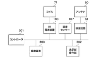
図4を参照すると、図2で説明したコイル(以下、IHコイルとも呼ぶ)71には、IH電源装置100が接続されている。そして、電磁誘導加熱(IH)電源装置100及び検波回路81は、信号線を介して相互に接続されており、この信号線には、後述する温度センサー107が接続されている。また、この信号線には、コントローラ301が接続されている。
Referring to FIG. 4, an IH
さらに、信号線には、駆動装置303及び表示・操作部302が接続され、コントローラ301の制御下で、駆動装置303は、前述のローラ軸体74等を駆動する。表示・操作部302は、ユーザがコントローラ301に各種指令等を与えるとともに、コントローラ301からの各種情報を表示するために用いられる。
Further, a
図5は、図4に示す加熱制御装置で用いられるIH電源装置100の一例を説明するための図である。
FIG. 5 is a diagram for explaining an example of the IH
図5を参照して、IH電源装置100は、直列共振型と呼ばれる電源装置であり、このIH電源装置100には、商用交流電源101が接続されている。
Referring to FIG. 5, IH
図示のように、IH電源装置100は、ダイオードブリッジ回路102、フィルタ用コンデンサ103、共振コンデンサ105、制御回路108、第1及び第2のスイッチ素子(例えば、insulated gate bipolar transistor(IGBT))111及び112、入力電圧検出部113、及び入力電流検出部114を有している。
As illustrated, the IH
IH電源装置100において、入力電圧検出部113は、商用交流電源101に並列に接続され、入力電流検出部114は、商用交流電源101に直列に接続されている。また、ダイオードブリッジ回路102の入力側が入力電圧検出部113に対して並列に配置されている。
In the IH
これら入力電圧検出部113及び入力電流検出部114は、それぞれ商用交流電源101の入力電圧及び入力電流を検出して、入力電圧検出信号及び入力電流検出信号を出力する。
The input
そして、ダイオードブリッジ回路102の出力側に、並列にフィルタ用コンデンサ103が接続され、このフィルタ用コンデンサ103に対して、直列に接続された第1及び第2のスイッチ素子111及び112が並列に配置されている。
A
第1及び第2のスイッチ素子111及び112は、そのエミッタとコレクタとが接続され、第1のスイッチ素子111のコレクタがダイオードブリッジ回路102に接続されている。また、第1及び第2のスイッチ素子111及び112の接続点が、前述のコイル71に接続されている。第2のスイッチ素子112のエミッタは、ダイオードブリッジ回路102に接続されるとともに、共振コンデンサ105を介してコイル71に接続されている。
The first and
制御回路108には、後述するモード信号がモード端子110aから与えられる。また、制御回路108には、前述の入力電圧検出信号及び入力電流検出信号が与えられる。さらに、制御回路108には、検波回路81からアンテナ出力Va(検出磁束電圧値)が与えられる。
The
なお、図示のように、定着ベルト72には、定着ベルト72の温度を検出するための温度センサー107が配置され、温度センサー107で検出された定着ベルト72の温度を示す温度検出信号が、制御回路108に与えられる。
As shown in the figure, the fixing
制御回路108は、これらモード信号、入力電圧検出信号、入力電流検出信号、温度検出信号、及びアンテナ出力Vaに応じて、第1及び第2のスイッチ素子111及び112のゲートにそれぞれ第1及び第2の制御信号(パルス信号)を与える。そして、これら第1及び第2の制御信号によって、第1及び第2のスイッチ素子111及び112は、オンオフ制御される(後述する)。
In response to the mode signal, the input voltage detection signal, the input current detection signal, the temperature detection signal, and the antenna output Va, the
なお、図4に示すコントローラ301は、IH電源装置100に対して、モード端子110aを介してモード信号を与える。図示の例では、モード信号には、電力制御モードを示す電力制御モード信号と温度制御モードを示す温度制御モード信号とがある。
4 gives a mode signal to the IH
一般的に、IH電源装置100の温度が低い状態から、記録媒体に定着するために必要な目標温度に温度を立ち上げる期間等、目標温度に立ち上げる期間は電力制御を行い、一度、目標温度に到達した後は、目標温度を維持するために温度制御モードに切り替わる。
In general, power control is performed during a period for raising the target temperature, such as a period for raising the temperature to a target temperature necessary for fixing to the recording medium from a state where the temperature of the IH
コントローラ301から電力制御モード信号が与えられると、制御回路108は、電力制御モードとなる。電力制御モードの際には、制御回路108は、入力電圧検出信号及び入力電流検出信号に応じて、入力電力を算出する。そして、制御回路108は、算出した入力電力に応じて、コイル71に印加される電力が所定の電力値となるように、第1及び第2のスイッチ素子111及び112をオンオフ制御する。
When a power control mode signal is given from the
一方、コントローラ301から温度制御モード信号が与えられると、制御回路108は、温度制御モードとなる。温度制御モードの際には、制御回路108は、温度センサー107からの温度検出信号に応じて定着ベルト72の表面温度を一定に保つ制御を行う。
On the other hand, when the temperature control mode signal is given from the
つまり、制御回路108は、温度センサー107から入力される温度検出信号が示す検出温度が予め規定された温度となるように、第1及び第2のスイッチ素子112及び113をオンオフ制御する。
That is, the
なお、図4に示すコントローラ301は、例えば、図1に示す画像形成装置1A全体を制御するためのものである。また、この例では、図4に示すコントローラ301と図5に示す制御回路108を別に構成して、制御回路108がIH電源装置100に収納された例について説明したが、コントローラ301と制御回路301を一体として、1つのマイクロプロセッサー等で構成するようにしてもよい。
Note that the
図6は、図4に示す加熱制御装置で用いられるアンテナの出力特性の一例を示す図である。 FIG. 6 is a diagram illustrating an example of output characteristics of an antenna used in the heating control apparatus illustrated in FIG. 4.
図6を参照すると、横軸は、IH電源装置100の入力電力Win(W)及び最大電力に対する割合(%)を示し、縦軸は、アンテナ80のアンテナ出力Vaを示している。そして、直線5aは、IH電源装置100の入力電圧Vinが100Vである場合に、定着ベルト72の25%(1/4)に異常が発生した際の入力電力Winとアンテナ出力Vaとの関係の一例を表している。
Referring to FIG. 6, the horizontal axis indicates the input power Win (W) and the ratio (%) with respect to the maximum power of the IH
また、直線5bは、IH電源装置100の入力電圧Vinが230Vである場合に、定着ベルト72の25%(1/4)に異常が発生した際の入力電力Winとアンテナ出力Vaとの関係の一例を表している。
Further, the
前述したように、アンテナ80は、アンテナ80と鎖交する磁束の変化に応じた出力を発生する。そして、この磁束は、コイル71に流れる電流に応じて発生する。
As described above, the
また、IH電源装置100によって、入力電力(入力電力値)Winが所定の電力値に制御されていても、入力電圧Vinが変化すると、コイル71に流れる電流波形が変化する。従って、入力電力Winが所定の電力値に制御されていても、入力電圧Vinが変化すれば、検波回路81から出力されるアンテナ出力Vaが変化する。
Even if the input power (input power value) Win is controlled to a predetermined power value by the IH
例えば、入力電圧Vin=230Vで、入力電力Win=800Wである場合に、定着ベルト72の25%(1/4)に異常が発生すると、アンテナ出力Vaは、0.25Vとなる。
For example, when the input voltage Vin = 230V and the input power Win = 800W, if an abnormality occurs in 25% (1/4) of the fixing
一方、入力電力Win=800Wの場合でも、入力電圧Vinが100Vとなると、アンテナ出力Vaは、0.2Vとなる。 On the other hand, even when the input power Win = 800 W, when the input voltage Vin becomes 100 V, the antenna output Va becomes 0.2 V.
また、入力電圧Vin=100Vである場合において、入力電力Winが1200Wであると、アンテナ出力Vaは0.3Vとなる。 When the input voltage Vin = 100V and the input power Win is 1200 W, the antenna output Va is 0.3V.
このように、定着ベルト72の25%に異常が発生した場合においても、入力電圧Vin又は入力電力Winが異なると、アンテナ出力Va(つまり、異常検知レベル)が異なることになる。
As described above, even when an abnormality has occurred in 25% of the fixing
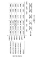
図7は、図4に示す加熱制御装置で用いられる異常検知閾値テーブルの一例を示す図である。 FIG. 7 is a diagram illustrating an example of an abnormality detection threshold value table used in the heating control apparatus illustrated in FIG. 4.
図7に示す異常検知閾値テーブルは、定着ベルト72の25%に異常が発生した際の異常検知閾値、つまり、異常検知レベルを表している。
The abnormality detection threshold value table shown in FIG. 7 represents an abnormality detection threshold when an abnormality has occurred in 25% of the fixing
この異常検知閾値テーブルは、IH電源装置100の入力電圧Vinと入力電力Winとに応じた異常検知閾値を設定するためのものであり、図示の例では、入力電圧Vin及び入力電力Winがそれぞれ6段階に分かれている。
This abnormality detection threshold value table is for setting an abnormality detection threshold value according to the input voltage Vin and input power Win of the IH
具体的には、入力電圧Vinは、85V以下、85Vを越え110V以下、110Vを越え135V以下、135Vを越え185V以下、185Vを越え225V以下、そして、225Vを越え265V以下の6段階に分けられている。 Specifically, the input voltage Vin is divided into six levels of 85V or less, over 85V to 110V, over 110V to 135V, over 135V to 185V, over 185V to 225V, and over 225V to 265V. ing.
また、入力電力Winは、200W以下、200Wを越え400W以下、400Wを越え600W以下、600Wを越え800W以下、800Wを越え1000WV以下、そして、1000WVを越え1200WV以下の6段階に分けられている。なお、上記の段階は、一例であり、段階をさらに細かくするようにしてもよい。 The input power Win is divided into six stages of 200 W or less, over 200 W and over 400 W, over 400 W over 600 W, over 600 W over 800 W, over 800 W over 1000 WV, and over 1000 WV over 1200 WV. In addition, said step is an example and you may make it make a step finer.
図7に示すように、例えば、入力電圧Vinが110Vを越え135V以下で、入力電力Winが600Wを越え800W以下である場合には、異常検知閾値として、0.216Vが設定される。この場合には、アンテナ出力Vaが0.216Vを越えると、制御回路108は、定着ベルト72の25%以上に異常が発生したと判定する。
As shown in FIG. 7, for example, when the input voltage Vin exceeds 110V and is 135V or less, and the input power Win exceeds 600W and is 800W or less, 0.216V is set as the abnormality detection threshold. In this case, when the antenna output Va exceeds 0.216 V, the
図8は、図4に示す加熱制御装置において、定着ベルトの異常検知を説明するためのフローチャートである。 FIG. 8 is a flowchart for explaining detection of abnormality of the fixing belt in the heating control apparatus shown in FIG.
ここで、図1、図2、図4、図5、図7、及び図8を参照して、いま、図1に示す画像形成装置1Aにおいて、画像形成動作が開始されると、コントローラ301からIH電源装置100に対して加熱命令を示す加熱動作開始信号が与えられる。IH電源装置100、つまり、制御回路108は、加熱動作開始信号を受けると、コイル71に対して高周波電力を印加する。さらに、IH電源装置100、つまり、制御回路108は、次のようにして、定着ベルト72の異常検知を実行する。なお、画像形成動作中は、常に加熱開始信号が出力され、定着装置7は温められている。
Here, referring to FIGS. 1, 2, 4, 5, 7, and 8, when an image forming operation is started in the image forming apparatus 1 </ b> A shown in FIG. A heating operation start signal indicating a heating command is given to the IH
なお、図示の例においては、図7に示す異常検知閾値テーブルは、制御回路108に内蔵される記憶部(図示せず)に格納されているものとする。
In the illustrated example, it is assumed that the abnormality detection threshold value table illustrated in FIG. 7 is stored in a storage unit (not illustrated) built in the
まず、制御回路108は、IH電源装置100に印加される入力電圧Vinを確認するため、入力電圧検出部113から入力電圧検出信号を得る(入力電圧Vin確認:ステップS701)。続いて、制御回路108は、IH電源装置100に印加される入力電流Iinを確認するため、入力電流検出部114から入力電流検出信号を得る(入力電流Iin確認:ステップS702)。
First, the
ここでは、入力電圧検出信号が示す入力電圧をVinで表し、入力電流検出信号が示す入力電流をIinで表す。制御回路108は、入力電圧検出信号と入力電流検出信号とに基づいて、入力電力Win=Vin×Iinを算出する。
Here, the input voltage indicated by the input voltage detection signal is represented by Vin, and the input current indicated by the input current detection signal is represented by Iin. The
そして、制御回路108は、入力電圧Vinと入力電力Winとに応じて、図7に示す異常検知閾値テーブルを参照して、異常検知閾値(異常検知規格値)Vkを決定する(ステップS703)。
Then, the
例えば、入力電圧Vin=115V、入力電流Iin=6Aの場合、入力電力Win=690Wとなる。そして、制御回路108は、入力電圧Vin=115Vと入力電力Win=690Wとに基づいて、異常検知閾値テーブルを参照し、異常検知閾値Vk=0.216Vと決定する。続いて、制御回路108は、検波回路81から与えられるアンテナ出力Va(V)と異常検知閾値Vk(V)とを比較する(ステップS704)。
For example, when the input voltage Vin = 115 V and the input current Iin = 6 A, the input power Win = 690 W. Then, the
いま、アンテナ電圧値(V)が閾値Vkを越えていると(ステップS704において、YES)、制御回路108は、定着ベルト72に異常が発生したと判定する。そして、制御回路108は、第1及び第2のスイッチ素子112及び113をオフにして、コイル71に対する電力の供給を停止する(電源駆動停止:ステップS705)。
If antenna voltage value (V) now exceeds threshold value Vk (YES in step S704),
制御回路108は、定着ベルト72に異常が発生したと判断した際には、コントローラ301(図4)に、定着ベルト72に異常が発生した旨連絡するとともに、IH電源装置100の駆動停止を連絡する。
When the
これによって、コントローラ301は、駆動装置302による定着ベルト72の駆動を停止制御する。さらに、コントローラ301は、定着ベルト72に異常が発生したことを表示・操作部302に表示する。
As a result, the
一方、アンテナ出力Va(V)が、異常検知閾値Vk以下であると(ステップS704において、NO)、制御回路108は、その旨(つまり、定着ベルト72に異常がない旨)をコントローラ301に通知する。そして、制御回路108は、温度センサー107からの温度検出信号が示す検出温度が、所定の温度に達したか否かを判定する。つまり、制御回路108は、加熱終了か否かを判定する(ステップS706)。
On the other hand, if the antenna output Va (V) is equal to or less than the abnormality detection threshold Vk (NO in step S704), the
画像形成動作が終了し、加熱動作開始信号が無くなると(ステップS706において、YES)、制御回路108は、ステップS705に移行して、電源駆動停止を実行する。
When the image forming operation is finished and there is no heating operation start signal (YES in step S706),
画像形成動作が継続している場合、つまり、加熱動作開始信号が出力されている場合(ステップS706において、NO)、制御回路108は、ステップS701に移行して、入力電圧Vinの確認を繰り返し行う。
When the image forming operation continues, that is, when the heating operation start signal is output (NO in step S706), the
上述のように、定着装置7、つまり、定着ベルト72の加熱動作中においては、制御回路108は、常に入力電圧Vinと入力電流Iinを確認する。そして、制御回路108は、入力電圧Vin及び入力電力Winの変化に合わせて、異常検知閾値Vkを変更・更新することになる。従って、制御回路108は閾値変更部として機能することになる。
As described above, during the heating operation of the fixing
このように、入力電圧Vinも考慮して、定着ベルト72の異常を検知するようにしたので、定着ベルト72の異常を精度よく、しかも安定して検知することができることになる。
As described above, since the abnormality of the fixing
つまり、AC入力電圧又は入力電力等の動作条件が変わっても、定着ベルト72の異常を精度よく検知して、定着ベルト72の異常状態検知のバラツキを少なくすることができる。
That is, even if the operating conditions such as the AC input voltage or the input power change, the abnormality of the fixing
なお、制御回路108は、上述した電力制御モード及び温度制御モードの他に、定着ベルト72の異常を検知する検知機能を有していることになる。
The
上記のようにして、定着ベルト72の異常検知を精度よく行うことができるので、結果的に、異常検知レベルを下げることが可能となる。このことは、定着ベルト72に異常が発生した際も、より早い段階で(小さな異常で)異常を検知することができることを意味する。そして、早期に異常が検知できれば、無駄に複写等の印刷が行われることがなく、記録材及びトナー等の無駄防止に寄与するものである。
As described above, the abnormality detection of the fixing
なお、上述の実施形態においては、IH電源装置100として直列共振タイプのものを用いたが、並列共振タイプ等の他のタイプのものを用いるようにしても、同様の効果を得ることができる。
In the above-described embodiment, the series resonance type device is used as the IH
さらに、図2に示す例では、アンテナ80を、定着ベルト72を挟んでコイル71と対向する位置に配置したが、アンテナ80の配置位置は、この例に限定されない。いずれにしても、アンテナ80は、定着ベルト72に異常が発生した場合に、磁束分布の変化を検出できる位置に配置すればよい。
Further, in the example shown in FIG. 2, the
また、上述の例では、入力電流検出部114によってIH電源装置100の入力電流を検出するとともに、入力電圧検出部113によってIH電源装置100の入力電圧を検出して、IH電源装置100の入力電力を求めるようにした。この代わりに、コイル71に流れる電流を検出して、入力電圧検出部113における電圧検出結果とコイル71に流れる電流の電流検出結果とに基づいて入力電力を求めるようにしてもよい。
In the above example, the input
加えて、上述の例では、定着ベルト72の異常検知に係る異常検知閾値Vkを、入力電圧Vinと入力電力Winとに応じて変更したが、同様にして、入力電圧Vinと入力電力Winとに応じて検波回路81からのアンテナ出力Vaを補正するようにしてもよく、さらには、異常検知閾値とアンテナ出力Vaとを補正するようにしてもよい。
In addition, in the above-described example, the abnormality detection threshold value Vk related to abnormality detection of the fixing
また、上述の例では、定着ベルト72の異常を検知する場合について説明したが、定着装置7が加熱ローラによって、記録材P上の未定着トナー画像を定着するタイプである場合には、加熱ローラの異常が検知されることになる。
In the above-described example, the case where the abnormality of the fixing
図9は、図4に示す加熱制御装置で用いられる電源装置(IH電源装置)100aの他の例を説明するための図である。 FIG. 9 is a diagram for explaining another example of the power supply device (IH power supply device) 100a used in the heating control device shown in FIG.
図9において、図5と同一の構成要素について同一の参照番号を付し、その説明を省略する。図9に示すIH電源装置100aにおいて、制御回路は、図5に示す制御回路108とその機能が異なるので、ここでは、参照番号108aを付す。
In FIG. 9, the same components as those in FIG. 5 are denoted by the same reference numerals, and the description thereof is omitted. In the IH
図示の制御回路108aには、図4に示すコントローラ301から、モード信号の他に、電力指令値信号、例えば、電力指令PWM(パルス幅変調)信号が電力指令端子110bを介して与えられる。
In addition to the mode signal, the
コントローラ301(図4)は、電力制御モードの際には、IH電源装置100に電力制御モード信号を与えるとともに、電力指令PWM信号を与える。電力制御モードの際には、制御回路108aは、入力電圧検出部113からの入力電圧検出信号が示す入力電圧Vinに応じて電力指令PWM信号のオンオフ時間を調整する。
In the power control mode, the controller 301 (FIG. 4) provides a power control mode signal to the IH
例えば、制御回路108aは、入力電圧Vinと予め設定された電圧値とを比較する。そして、入力電圧Vinが予め設定された電圧値よりも大きいと、制御回路108aは、その差分(入力電圧Vinと予め設定された電圧値との差分)に応じて、電力指令PWM信号のオン時間を短くして、電力指令PWM信号を修正PWM信号とする。
For example, the
一方、入力電圧Vinが予め設定された電圧値より小さいと、制御回路108aは、その差分に応じて、電力指令PWM信号のオン時間を長くして、電力指令PWM信号を修正PWM信号とする。
On the other hand, when the input voltage Vin is smaller than a preset voltage value, the
そして、制御回路108aは、この修正PWM信号に基づいた第1及び第2の制御信号に応じて第1及び第2のスイッチ素子111及び112をオンオフ制御する。なお、入力電圧Vin=予め設定された電圧値である際には、制御回路108aは電力指令PWM信号の調整は行わない。
Then, the
図示のIH電源装置100aにおいて、定着ベルト72の異常を検知する際には、入力電圧Vinと電力指令PWM信号が示す電力指令値Waとに応じて、図7で説明した異常検知閾値テーブルを検索して、異常検知閾値Vkを決定する。そして、図8で説明したようにして、制御回路108aは、定着ベルト72に異常があるか否かについて検知する。
When detecting an abnormality of the fixing
なお、他の動作は、図5に示すIH電源装置100と同様であるので、説明を省略する。
Other operations are the same as those of the IH
この場合、入力電圧Vinと電力指令値Waとによって、異常検知閾値テーブルを検索して、異常検知閾値Vkを決定する関係上、異常検知精度及び異常検知に要する時間について、図5に示すIH電源装置100と比較して若干劣る。
In this case, the abnormality detection threshold value table is searched based on the input voltage Vin and the electric power command value Wa and the abnormality detection threshold value Vk is determined. Therefore, the abnormality detection accuracy and the time required for abnormality detection are shown in FIG. It is slightly inferior compared with the
しかしながら、図9に示すIH電源装置においては、図5に示す入力電流検出部114が不要となり、この結果、部品点数の面でその構成が簡素となるという利点がある。
However, the IH power supply device shown in FIG. 9 does not require the input
そして、入力電流検出部114を備えない関係上、図5に示すIH電源装置100のように、入力電力Winを演算する必要がない。この結果、制御回路100aは、制御回路100に比べてその構成が簡素となるという利点もある。
Since the input
上述の例では、定着装置7における定着ベルト72を加熱する際、その異常を検知する手法については説明したが、定着ローラによってトナー像の定着を行う定着装置においては、定着ローラが被加熱物となる。また、定着装置7に限らず、電磁誘導加熱によって加熱される被加熱物の異常を検知する際に、同様にして、本発明を適用することができる。
In the above-described example, the method of detecting the abnormality when the fixing
上述の説明から明らかなように、電源装置100又は100aが電磁誘導加熱コイル71に高周波電力を印加するための電源装置として機能する。また、アンテナ80及び検波回路81が、被加熱物である定着ベルト72を介在させて電磁誘導加熱コイル71からの磁束を検知して当該磁束に応じた電圧を検出磁束電圧値(アンテナ出力)として出力する磁束検出手段として機能する。
As is clear from the above description, the
そして、制御回路108又は108aが高周波電力の電力値を規定する電力設定値と電源装置100又は100aに入力される入力電圧との関係に応じて磁束電圧値及び異常検知閾値の少なくとも一方を変更する変更手段として機能することになる。さらに、制御回路108又は108aは、変更された磁束電圧値及び異常検知閾値に応じて定着ベルト72の異常を判定する異常判定手段としても機能することになる。
The
なお、制御回路108又は108aには、上記の電力設定値と入力電圧とに対応付けて複数の異常検知閾値が規定された異常検知閾値テーブルが備えられ、制御回路108又は108aは、電力設定値と入力電圧とに応じて異常検知閾値テーブルを検索して、異常検知閾値の1つを得ることによって異常検知閾値の変更を行うことになる。
The
また、制御回路108又は108aと第1及び第2のスイッチ素子111及び112とは、温度センサー72で検知される検出温度と予め設定された温度とに基づいて電源装置100又は100aを制御して、電磁誘導加熱コイル71に与える高周波電力を調整する第1の電力制御手段として機能する。
The
そして、制御回路108又は108aと第1及び第2のスイッチ素子111及び112とは、電源装置100又は100aに入力される電力と予め設定された所定の電力値とに応じて、電源装置100又は100aを制御して、電磁誘導加熱コイル71に与える高周波電力を調整する第2の電力制御手段としても機能することになる。
Then, the
さらに、制御回路108又は108aと第1及び第2のスイッチ素子111及び112とは、検出磁束電圧値が異常検知閾値以上であると、電源装置100又は110aを停止する停止手段としても機能する。
Furthermore, the
71 コイル
72 定着ベルト
80 アンテナ
81 検波回路
100,100a IH電源装置
113 入力電圧検出部
114 入力電流検出部
108,108a 制御回路
301 コントローラ
71
Claims (10)
前記電磁誘導加熱コイルに前記高周波電力を印加するための電源装置と、
前記被加熱物を介在させて前記電磁誘導加熱コイルからの磁束を検知して当該磁束に応じた電圧を検出磁束電圧値として出力する磁束検出手段と、
前記高周波電力の電力値を規定する電力設定値と前記電源装置に入力される入力電圧との関係に応じて前記検出磁束電圧値及び異常検知閾値の少なくとも一方を変更する変更手段と、
前記変更手段によって変更された前記検出磁束電圧値及び前記異常検知閾値に応じて前記被加熱物の異常を判定する異常判定手段とを有することを特徴とする加熱制御装置。 In a heating control device for applying high frequency power to an electromagnetic induction heating coil and controlling heating of an object to be heated by the electromagnetic induction heating coil,
A power supply device for applying the high-frequency power to the electromagnetic induction heating coil;
Magnetic flux detection means for detecting a magnetic flux from the electromagnetic induction heating coil with the object to be heated interposed therebetween and outputting a voltage corresponding to the magnetic flux as a detected magnetic flux voltage value;
Changing means for changing at least one of the detected magnetic flux voltage value and the abnormality detection threshold according to a relationship between a power setting value defining the power value of the high-frequency power and an input voltage input to the power supply device;
A heating control apparatus comprising: an abnormality determining unit that determines an abnormality of the object to be heated in accordance with the detected magnetic flux voltage value changed by the changing unit and the abnormality detection threshold value.
前記電力設定値と前記入力電圧とに応じて前記異常検知閾値テーブルを検索して、前記異常検知閾値の1つを得ることによって前記異常検知閾値の変更を行う閾値変更部とを有することを特徴とする請求項1〜4のいずれか1項に記載の加熱制御装置。 The change means includes an abnormality detection threshold table in which a plurality of the abnormality detection thresholds are defined in association with the power setting value and the input voltage;
A threshold value changing unit that searches the abnormality detection threshold value table according to the power setting value and the input voltage and obtains one of the abnormality detection threshold values to change the abnormality detection threshold value. The heating control apparatus according to any one of claims 1 to 4 .
前記検出温度と予め設定された温度とに基づいて前記電源装置を制御して前記電磁誘導加熱コイルに与える前記高周波電力を調整する第1の電力制御手段とを有することを特徴とする請求項1〜5のいずれか1項に記載の加熱制御装置。 Temperature detecting means for detecting the temperature of the object to be heated and outputting the detected temperature;
Claim 1, characterized in that it comprises a first power control means for adjusting the high-frequency power to be supplied to the electromagnetic induction heating coil by controlling the power supply based on said detected temperature with a preset temperature The heating control apparatus according to any one of?
電磁誘導加熱コイルに高周波電力を印加して、前記記録材に転写されたトナー像を加熱定着させる際の加熱制御を行う請求項1〜9のいずれか1項に記載の加熱制御装置とを有することを特徴とする画像形成装置。 Transfer means for transferring a toner image to a recording material;
By applying a high frequency power to the electromagnetic induction heating coil, and a heating control device according to any one of claims 1-9 for performing heating control of the time of heat fixing the toner image transferred on the recording material An image forming apparatus.
Priority Applications (2)
| Application Number | Priority Date | Filing Date | Title |
|---|---|---|---|
| JP2010106403A JP5465082B2 (en) | 2010-05-06 | 2010-05-06 | Heating control apparatus and image forming apparatus |
| US13/100,525 US8929753B2 (en) | 2010-05-06 | 2011-05-04 | Heating control device, heating control method, and image forming apparatus |
Applications Claiming Priority (1)
| Application Number | Priority Date | Filing Date | Title |
|---|---|---|---|
| JP2010106403A JP5465082B2 (en) | 2010-05-06 | 2010-05-06 | Heating control apparatus and image forming apparatus |
Publications (3)
| Publication Number | Publication Date |
|---|---|
| JP2011237479A JP2011237479A (en) | 2011-11-24 |
| JP2011237479A5 JP2011237479A5 (en) | 2013-06-20 |
| JP5465082B2 true JP5465082B2 (en) | 2014-04-09 |
Family
ID=44902007
Family Applications (1)
| Application Number | Title | Priority Date | Filing Date |
|---|---|---|---|
| JP2010106403A Expired - Fee Related JP5465082B2 (en) | 2010-05-06 | 2010-05-06 | Heating control apparatus and image forming apparatus |
Country Status (2)
| Country | Link |
|---|---|
| US (1) | US8929753B2 (en) |
| JP (1) | JP5465082B2 (en) |
Families Citing this family (6)
| Publication number | Priority date | Publication date | Assignee | Title |
|---|---|---|---|---|
| JP5669511B2 (en) * | 2010-10-12 | 2015-02-12 | キヤノン株式会社 | Heating apparatus and image forming apparatus |
| JP2012083545A (en) * | 2010-10-12 | 2012-04-26 | Canon Inc | Heater and image forming device |
| CN104076726B (en) * | 2014-07-09 | 2017-02-01 | 安徽研扬科贸有限公司 | Heating wire power supply control method |
| JP2019082603A (en) * | 2017-10-31 | 2019-05-30 | エイチピー プリンティング コリア カンパニー リミテッド | Fixing device |
| JP2019115185A (en) * | 2017-12-25 | 2019-07-11 | 株式会社リコー | Power supply device and image forming apparatus |
| CN113126168A (en) * | 2019-12-31 | 2021-07-16 | 广东美的白色家电技术创新中心有限公司 | Detection method, device, equipment and storage medium |
Family Cites Families (10)
| Publication number | Priority date | Publication date | Assignee | Title |
|---|---|---|---|---|
| JPH0375805A (en) * | 1989-08-17 | 1991-03-29 | Fuji Xerox Co Ltd | Image forming device |
| JP2925366B2 (en) * | 1991-07-17 | 1999-07-28 | キヤノン株式会社 | Image forming device |
| JP3902937B2 (en) * | 2001-10-23 | 2007-04-11 | キヤノン株式会社 | Image heating device |
| US7065315B2 (en) * | 2003-06-30 | 2006-06-20 | Kabushiki Kaisha Toshiba | Fixing apparatus |
| JP4449547B2 (en) * | 2003-09-17 | 2010-04-14 | コニカミノルタビジネステクノロジーズ株式会社 | Image forming apparatus |
| JP4933161B2 (en) * | 2006-06-08 | 2012-05-16 | キヤノン株式会社 | Image heating device |
| JP2009092835A (en) * | 2007-10-05 | 2009-04-30 | Toshiba Home Technology Corp | Induction heating apparatus |
| JP5102066B2 (en) * | 2008-02-26 | 2012-12-19 | キヤノン株式会社 | Fixing apparatus and image forming apparatus |
| JP2010002523A (en) * | 2008-06-19 | 2010-01-07 | Konica Minolta Business Technologies Inc | Electromagnetic induction heating device, fixing device and image forming apparatus |
| JP5455603B2 (en) * | 2009-12-17 | 2014-03-26 | キヤノン株式会社 | Image forming apparatus having an induction heating type fixing device |
-
2010
- 2010-05-06 JP JP2010106403A patent/JP5465082B2/en not_active Expired - Fee Related
-
2011
- 2011-05-04 US US13/100,525 patent/US8929753B2/en not_active Expired - Fee Related
Also Published As
| Publication number | Publication date |
|---|---|
| US20110274449A1 (en) | 2011-11-10 |
| US8929753B2 (en) | 2015-01-06 |
| JP2011237479A (en) | 2011-11-24 |
Similar Documents
| Publication | Publication Date | Title |
|---|---|---|
| JP5465082B2 (en) | Heating control apparatus and image forming apparatus | |
| US7039336B2 (en) | Fixing device and image forming apparatus | |
| US9501003B2 (en) | Image forming apparatus | |
| US9551950B2 (en) | Image forming apparatus | |
| JP2010015130A (en) | Image forming apparatus | |
| JP5641749B2 (en) | Image forming apparatus | |
| JP4630576B2 (en) | Power control device | |
| JP2020046579A (en) | Power supply device and image forming apparatus | |
| JP6632265B2 (en) | Image forming apparatus, temperature control method | |
| US9411279B2 (en) | Image forming and fixing apparatuses having fixing and pressing rotating member and rectification element | |
| US20100124429A1 (en) | Fixing controller and image forming apparatus | |
| JP5629566B2 (en) | Image forming apparatus | |
| JP5904807B2 (en) | Power supply and image forming apparatus | |
| JP5455603B2 (en) | Image forming apparatus having an induction heating type fixing device | |
| US9316970B2 (en) | Image forming apparatus and method for controlling power supply to heater of fixing unit based on resistance value of heater | |
| JP2009048090A (en) | Image forming apparatus | |
| JP4903321B2 (en) | Heater driving device, fixing device, and image forming apparatus | |
| JP2019101408A (en) | Power supply device and image forming apparatus | |
| JP2019105664A (en) | Power supply device and image forming apparatus | |
| JP2018116187A (en) | Image forming apparatus | |
| JP2002328553A (en) | Heating device and image forming device | |
| JP2004304866A (en) | Power supply unit and image-forming apparatus | |
| JP6051564B2 (en) | Fixing apparatus and image forming apparatus | |
| JP2016096702A (en) | Power supply and image formation apparatus | |
| JP2012138303A (en) | Induction heating apparatus and image formation apparatus |
Legal Events
| Date | Code | Title | Description |
|---|---|---|---|
| A521 | Request for written amendment filed |
Free format text: JAPANESE INTERMEDIATE CODE: A523 Effective date: 20130502 |
|
| A621 | Written request for application examination |
Free format text: JAPANESE INTERMEDIATE CODE: A621 Effective date: 20130502 |
|
| A977 | Report on retrieval |
Free format text: JAPANESE INTERMEDIATE CODE: A971007 Effective date: 20131209 |
|
| TRDD | Decision of grant or rejection written | ||
| A01 | Written decision to grant a patent or to grant a registration (utility model) |
Free format text: JAPANESE INTERMEDIATE CODE: A01 Effective date: 20131224 |
|
| A61 | First payment of annual fees (during grant procedure) |
Free format text: JAPANESE INTERMEDIATE CODE: A61 Effective date: 20140121 |
|
| LAPS | Cancellation because of no payment of annual fees |