JP5316640B2 - Driving support device - Google Patents
Driving support device Download PDFInfo
- Publication number
- JP5316640B2 JP5316640B2 JP2011519348A JP2011519348A JP5316640B2 JP 5316640 B2 JP5316640 B2 JP 5316640B2 JP 2011519348 A JP2011519348 A JP 2011519348A JP 2011519348 A JP2011519348 A JP 2011519348A JP 5316640 B2 JP5316640 B2 JP 5316640B2
- Authority
- JP
- Japan
- Prior art keywords
- deceleration control
- moving body
- obstacle
- areas
- length
- Prior art date
- Legal status (The legal status is an assumption and is not a legal conclusion. Google has not performed a legal analysis and makes no representation as to the accuracy of the status listed.)
- Expired - Fee Related
Links
Images

Classifications
-
- B—PERFORMING OPERATIONS; TRANSPORTING
- B60—VEHICLES IN GENERAL
- B60T—VEHICLE BRAKE CONTROL SYSTEMS OR PARTS THEREOF; BRAKE CONTROL SYSTEMS OR PARTS THEREOF, IN GENERAL; ARRANGEMENT OF BRAKING ELEMENTS ON VEHICLES IN GENERAL; PORTABLE DEVICES FOR PREVENTING UNWANTED MOVEMENT OF VEHICLES; VEHICLE MODIFICATIONS TO FACILITATE COOLING OF BRAKES
- B60T7/00—Brake-action initiating means
- B60T7/12—Brake-action initiating means for automatic initiation; for initiation not subject to will of driver or passenger
- B60T7/22—Brake-action initiating means for automatic initiation; for initiation not subject to will of driver or passenger initiated by contact of vehicle, e.g. bumper, with an external object, e.g. another vehicle, or by means of contactless obstacle detectors mounted on the vehicle
-
- A—HUMAN NECESSITIES
- A61—MEDICAL OR VETERINARY SCIENCE; HYGIENE
- A61G—TRANSPORT, PERSONAL CONVEYANCES, OR ACCOMMODATION SPECIALLY ADAPTED FOR PATIENTS OR DISABLED PERSONS; OPERATING TABLES OR CHAIRS; CHAIRS FOR DENTISTRY; FUNERAL DEVICES
- A61G5/00—Chairs or personal conveyances specially adapted for patients or disabled persons, e.g. wheelchairs
- A61G5/04—Chairs or personal conveyances specially adapted for patients or disabled persons, e.g. wheelchairs motor-driven
- A61G5/041—Chairs or personal conveyances specially adapted for patients or disabled persons, e.g. wheelchairs motor-driven having a specific drive-type
-
- B—PERFORMING OPERATIONS; TRANSPORTING
- B60—VEHICLES IN GENERAL
- B60T—VEHICLE BRAKE CONTROL SYSTEMS OR PARTS THEREOF; BRAKE CONTROL SYSTEMS OR PARTS THEREOF, IN GENERAL; ARRANGEMENT OF BRAKING ELEMENTS ON VEHICLES IN GENERAL; PORTABLE DEVICES FOR PREVENTING UNWANTED MOVEMENT OF VEHICLES; VEHICLE MODIFICATIONS TO FACILITATE COOLING OF BRAKES
- B60T8/00—Arrangements for adjusting wheel-braking force to meet varying vehicular or ground-surface conditions, e.g. limiting or varying distribution of braking force
- B60T8/32—Arrangements for adjusting wheel-braking force to meet varying vehicular or ground-surface conditions, e.g. limiting or varying distribution of braking force responsive to a speed condition, e.g. acceleration or deceleration
- B60T8/58—Arrangements for adjusting wheel-braking force to meet varying vehicular or ground-surface conditions, e.g. limiting or varying distribution of braking force responsive to a speed condition, e.g. acceleration or deceleration responsive to speed and another condition or to plural speed conditions
-
- B—PERFORMING OPERATIONS; TRANSPORTING
- B62—LAND VEHICLES FOR TRAVELLING OTHERWISE THAN ON RAILS
- B62K—CYCLES; CYCLE FRAMES; CYCLE STEERING DEVICES; RIDER-OPERATED TERMINAL CONTROLS SPECIALLY ADAPTED FOR CYCLES; CYCLE AXLE SUSPENSIONS; CYCLE SIDE-CARS, FORECARS, OR THE LIKE
- B62K5/00—Cycles with handlebars, equipped with three or more main road wheels
- B62K5/02—Tricycles
- B62K5/023—Tricycles specially adapted for disabled riders, e.g. personal mobility type vehicles with three wheels
- B62K5/025—Tricycles specially adapted for disabled riders, e.g. personal mobility type vehicles with three wheels power-driven
-
- B—PERFORMING OPERATIONS; TRANSPORTING
- B62—LAND VEHICLES FOR TRAVELLING OTHERWISE THAN ON RAILS
- B62K—CYCLES; CYCLE FRAMES; CYCLE STEERING DEVICES; RIDER-OPERATED TERMINAL CONTROLS SPECIALLY ADAPTED FOR CYCLES; CYCLE AXLE SUSPENSIONS; CYCLE SIDE-CARS, FORECARS, OR THE LIKE
- B62K5/00—Cycles with handlebars, equipped with three or more main road wheels
- B62K5/02—Tricycles
- B62K5/027—Motorcycles with three wheels
-
- B—PERFORMING OPERATIONS; TRANSPORTING
- B62—LAND VEHICLES FOR TRAVELLING OTHERWISE THAN ON RAILS
- B62K—CYCLES; CYCLE FRAMES; CYCLE STEERING DEVICES; RIDER-OPERATED TERMINAL CONTROLS SPECIALLY ADAPTED FOR CYCLES; CYCLE AXLE SUSPENSIONS; CYCLE SIDE-CARS, FORECARS, OR THE LIKE
- B62K5/00—Cycles with handlebars, equipped with three or more main road wheels
- B62K5/02—Tricycles
- B62K5/05—Tricycles characterised by a single rear wheel
-
- A—HUMAN NECESSITIES
- A61—MEDICAL OR VETERINARY SCIENCE; HYGIENE
- A61G—TRANSPORT, PERSONAL CONVEYANCES, OR ACCOMMODATION SPECIALLY ADAPTED FOR PATIENTS OR DISABLED PERSONS; OPERATING TABLES OR CHAIRS; CHAIRS FOR DENTISTRY; FUNERAL DEVICES
- A61G2203/00—General characteristics of devices
- A61G2203/10—General characteristics of devices characterised by specific control means, e.g. for adjustment or steering
- A61G2203/22—General characteristics of devices characterised by specific control means, e.g. for adjustment or steering for automatically guiding movable devices, e.g. stretchers or wheelchairs in a hospital
-
- A—HUMAN NECESSITIES
- A61—MEDICAL OR VETERINARY SCIENCE; HYGIENE
- A61G—TRANSPORT, PERSONAL CONVEYANCES, OR ACCOMMODATION SPECIALLY ADAPTED FOR PATIENTS OR DISABLED PERSONS; OPERATING TABLES OR CHAIRS; CHAIRS FOR DENTISTRY; FUNERAL DEVICES
- A61G2203/00—General characteristics of devices
- A61G2203/30—General characteristics of devices characterised by sensor means
- A61G2203/40—General characteristics of devices characterised by sensor means for distance
-
- A—HUMAN NECESSITIES
- A61—MEDICAL OR VETERINARY SCIENCE; HYGIENE
- A61G—TRANSPORT, PERSONAL CONVEYANCES, OR ACCOMMODATION SPECIALLY ADAPTED FOR PATIENTS OR DISABLED PERSONS; OPERATING TABLES OR CHAIRS; CHAIRS FOR DENTISTRY; FUNERAL DEVICES
- A61G5/00—Chairs or personal conveyances specially adapted for patients or disabled persons, e.g. wheelchairs
- A61G5/04—Chairs or personal conveyances specially adapted for patients or disabled persons, e.g. wheelchairs motor-driven
- A61G5/041—Chairs or personal conveyances specially adapted for patients or disabled persons, e.g. wheelchairs motor-driven having a specific drive-type
- A61G5/046—Chairs or personal conveyances specially adapted for patients or disabled persons, e.g. wheelchairs motor-driven having a specific drive-type at least three driven wheels
-
- A—HUMAN NECESSITIES
- A61—MEDICAL OR VETERINARY SCIENCE; HYGIENE
- A61G—TRANSPORT, PERSONAL CONVEYANCES, OR ACCOMMODATION SPECIALLY ADAPTED FOR PATIENTS OR DISABLED PERSONS; OPERATING TABLES OR CHAIRS; CHAIRS FOR DENTISTRY; FUNERAL DEVICES
- A61G5/00—Chairs or personal conveyances specially adapted for patients or disabled persons, e.g. wheelchairs
- A61G5/10—Parts, details or accessories
- A61G5/1005—Wheelchairs having brakes
- A61G5/1032—Wheelchairs having brakes engaging an element of the drive or transmission, e.g. drive belt, electrodynamic brake
-
- A—HUMAN NECESSITIES
- A61—MEDICAL OR VETERINARY SCIENCE; HYGIENE
- A61G—TRANSPORT, PERSONAL CONVEYANCES, OR ACCOMMODATION SPECIALLY ADAPTED FOR PATIENTS OR DISABLED PERSONS; OPERATING TABLES OR CHAIRS; CHAIRS FOR DENTISTRY; FUNERAL DEVICES
- A61G5/00—Chairs or personal conveyances specially adapted for patients or disabled persons, e.g. wheelchairs
- A61G5/10—Parts, details or accessories
- A61G5/1056—Arrangements for adjusting the seat
- A61G5/1059—Arrangements for adjusting the seat adjusting the height of the seat
Landscapes
- Engineering & Computer Science (AREA)
- Mechanical Engineering (AREA)
- Transportation (AREA)
- Public Health (AREA)
- Animal Behavior & Ethology (AREA)
- General Health & Medical Sciences (AREA)
- Life Sciences & Earth Sciences (AREA)
- Veterinary Medicine (AREA)
- Health & Medical Sciences (AREA)
- Electric Propulsion And Braking For Vehicles (AREA)
- Regulating Braking Force (AREA)
- Automatic Cycles, And Cycles In General (AREA)
- Traffic Control Systems (AREA)
Abstract
Description
本発明は、ホイールベース長が可変な移動体の走行を支援する走行支援装置に関する。 The present invention relates to a travel support device that supports travel of a moving body having a variable wheelbase length.
従来の走行支援装置としては、移動体の周辺の障害物に関する障害物情報を取得し、取得した障害物情報に基づいて移動体の減速制御を行うものが知られている。例えば、特許文献1には、車両(移動体)の前方を監視し、障害物が検知された場合に該障害物の存在するエリアに応じて減速制御を行う走行支援装置が開示されている。
As a conventional driving support device, there is known a device that acquires obstacle information related to obstacles around a moving body and performs deceleration control of the moving body based on the acquired obstacle information. For example,
ここで、ホイールベース長が可変な移動体においては、そのホイールベース長次第で、同様な減速制御を行う場合でも、不要な減速制御になったり減速が不足したり等、移動体の挙動が乱れるおそれがある。そのため、上述したような走行支援装置では、減速制御が適切に行われないおそれがある。 Here, in the case of a moving body with a variable wheelbase length, depending on the wheelbase length, even when similar deceleration control is performed, the behavior of the moving body is disturbed, such as unnecessary deceleration control or insufficient deceleration. There is a fear. Therefore, there is a possibility that deceleration control is not properly performed in the above-described travel support device.
そこで、本発明は、ホイールベース長が可変な移動体において、減速制御を適切に行うことが可能な走行支援装置を提供することを課題とする。 Therefore, an object of the present invention is to provide a travel support device capable of appropriately performing deceleration control in a moving body having a variable wheelbase length.
上記課題を解決するため、本発明に係る走行支援装置は、ホイールベース長が可変な移動体に搭載され、移動体の走行を支援する走行支援装置であって、移動体のホイールベース長に関するホイールベース長情報を取得するホイールベース長情報取得部と、移動体の周辺の障害物に関する障害物情報を取得する障害物情報取得部と、障害物情報取得部で取得した障害物情報に基づいて、移動体の減速制御を行う減速制御部と、を備え、減速制御部は、ホイールベース長情報取得部で取得したホイールベース長情報に応じて、減速制御を行うことを特徴とする。 In order to solve the above-described problem, a travel support device according to the present invention is a travel support device that is mounted on a mobile body having a variable wheelbase length and supports the travel of the mobile body, and is related to the wheel base length of the mobile body. Based on the obstacle information acquired by the wheel base length information acquisition unit for acquiring base length information, the obstacle information acquisition unit for acquiring obstacle information about obstacles around the moving object, and the obstacle information acquisition unit, A deceleration control unit that performs deceleration control of the moving body, and the deceleration control unit performs deceleration control according to the wheelbase length information acquired by the wheelbase length information acquisition unit.
この走行支援装置では、ホイールベース長情報に応じて減速制御が変更されるため、減速制御にホイールベース長を考慮することができ、減速制御が行われた際にホイールベース長に起因して移動体の挙動が乱れるのを抑制することができる。よって、ホイールベース長が可変な移動体において、減速制御を適切に行うことが可能となる。 In this travel support device, the deceleration control is changed according to the wheel base length information, so the wheel base length can be taken into account for the deceleration control, and the movement is caused by the wheel base length when the deceleration control is performed. It is possible to suppress the body behavior from being disturbed. Therefore, it is possible to appropriately perform the deceleration control in the moving body having a variable wheelbase length.
また、上記作用効果を好適に奏する構成として、具体的には、減速制御部は、移動体の周辺に設定された複数のエリアと複数のエリアごとに設定された減速パターンとを含む減速制御マップによって減速制御を行うものであって、複数のエリアのうち障害物が存在する障害物存在エリアを障害物情報に基づき検出したとき、検出した障害物存在エリアにおける減速パターンで減速制御を行うと共に、ホイールベース長情報に応じて、減速制御マップにおける複数のエリアを変更する構成が挙げられる。 In addition, as a configuration that preferably exhibits the above-described effects, specifically, the deceleration control unit includes a plurality of areas set around the moving body and a deceleration control map set for each of the plurality of areas. When the obstacle existence area where the obstacle exists among a plurality of areas is detected based on the obstacle information, the deceleration control is performed with the deceleration pattern in the detected obstacle existence area. The structure which changes the some area in a deceleration control map according to wheelbase length information is mentioned.
また、障害物情報取得部は、移動体の前方の障害物に関する障害物情報を取得し、減速制御部は、減速制御マップにおいて移動体の前方に設定された複数のエリアのうち少なくとも1つを、ホイールベース長が長くなるに従って前方に拡長するように、又は、ホイールベース長が短くなるに従って幅方向に拡長するように変更することが好ましい。ここで、通常、移動体の挙動特性にあっては、ホイールベース長が長い場合には、高速で旋回半径が大きい一方、ホイールベース長が短い場合には、低速で旋回半径が小さい。そのため、複数のエリアの少なくとも1つを、ホイールベース長が長くなるに従って前方に拡長するように、又は、ホイールベース長が短くなるに従って幅方向に拡長するように変更すると、
ホイールベース長による上記挙動特性に適応した好適な減速制御が可能となり、減速制御を一層適切に行うことが可能となる。The obstacle information acquisition unit acquires obstacle information related to an obstacle ahead of the moving body, and the deceleration control unit selects at least one of a plurality of areas set in front of the moving body in the deceleration control map. It is preferable to change so that the wheel base length increases forward as the wheel base length increases, or the width increases in the width direction as the wheel base length decreases. Here, normally, in the behavior characteristics of the moving body, when the wheel base length is long, the turning radius is high and the turning radius is large, whereas when the wheel base length is short, the turning radius is low and the turning radius is small. Therefore, when changing at least one of the plurality of areas so as to expand forward as the wheelbase length increases, or to increase in the width direction as the wheelbase length decreases,
Suitable deceleration control adapted to the above behavior characteristics by the wheelbase length becomes possible, and deceleration control can be performed more appropriately.
また、減速制御部は、移動体の速度が所定速度以下となるように減速制御を行う場合がある。この場合、移動体と障害物との接触を予防する上で好適な減速制御が行われることとなる。 Further, the deceleration control unit may perform deceleration control so that the speed of the moving body is equal to or lower than a predetermined speed. In this case, deceleration control suitable for preventing contact between the moving body and the obstacle is performed.
本発明によれば、ホイールベース長を変更可能な移動体において、減速制御を適切に行うことが可能となる。 ADVANTAGE OF THE INVENTION According to this invention, it becomes possible to perform deceleration control appropriately in the mobile body which can change wheelbase length.
以下、図面を参照しながら、本発明の好適な実施形態について詳細に説明する。なお、以下の説明では、同一又は相当要素には同一符号を付し、重複する説明は省略する。また、「前」「後」「左」「右」「上」「下」の語は、移動体の前後方向、左右方向、上下方向に対応するものである。 Hereinafter, preferred embodiments of the present invention will be described in detail with reference to the drawings. In the following description, the same or equivalent elements will be denoted by the same reference numerals, and redundant description will be omitted. The terms “front”, “rear”, “left”, “right”, “upper”, and “lower” correspond to the front-rear direction, the left-right direction, and the up-down direction of the moving body.
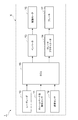
図1は、本発明の一実施形態に係る走行支援装置を示すブロック図である。図1に示すように、本実施形態の走行支援装置1は、ホイールベース長が可変な移動体Xに搭載されている。そこで、まず、この移動体Xについて説明する。
FIG. 1 is a block diagram showing a driving support apparatus according to an embodiment of the present invention. As shown in FIG. 1, the
図2(a)はショートホイールベース(歩行モード)時の移動体を示す側面図であり、図2(b)はロングホイールベース(走行モード)時の移動体を示す側面図である。図2に示すように、移動体Xは、1人乗りの電気車両であり、前方の2つの前輪Tf及び1つの後輪Trを含んで構成された3輪車両である。移動体Xでは、駆動モータ16(図1参照)の駆動によって駆動力を発生し、駆動モータ16の回生とブレーキ17(図1参照)によって制動力を発生する。この移動体Xは、車道、歩道、施設内の作業エリア等の様々な場所における路面、床、地面等の走行面21を走行可能とされている。この移動体Xは、運転者が座る座席22の左右に設けられた操作レバーやスイッチによって操作される。
FIG. 2A is a side view showing the moving body in the short wheel base (walking mode), and FIG. 2B is a side view showing the moving body in the long wheel base (running mode). As shown in FIG. 2, the moving body X is a single-seater electric vehicle, and is a three-wheeled vehicle including two front wheels Tf and one rear wheel Tr. In the moving body X, a driving force is generated by driving the driving motor 16 (see FIG. 1), and a braking force is generated by regenerating the
この移動体Xは、ホイールベース長(つまり、前輪Tfの軸中心と後輪Trの軸中心との間の距離)を可変しつつ、走行面21に対する傾斜状態を可変して変形する機構を備えている。ここでの移動体Xは、図2(a)に示す歩行モード(低速モード)と、図2(b)に示す走行モード(高速モード)との2つの走行モードで走行するよう変形可能されている。
The moving body X includes a mechanism that varies and changes the inclination state with respect to the
歩行モード時の移動体X1は、歩行者の歩行速度で走行可能とされ、例えば最高6km/hで走行可能とされている。また、歩行モード時の移動体X1は、走行モード時の移動体X2に対し、重心位置が高く、ホイールベース長が短くされている。これにより、移動体X1では、小さな旋回半径で旋回可能となっている。 The mobile body X1 in the walking mode can run at the walking speed of the pedestrian, and can run at a maximum of 6 km / h, for example. In addition, the moving body X1 in the walking mode has a higher center of gravity and a shorter wheelbase length than the moving body X2 in the traveling mode. Thereby, in the mobile body X1, it can turn with a small turning radius.
一方、走行モード時の移動体X2は、比較的高速で走行可能とされ、例えば最高30km/hで走行可能とされている。また、走行モード時の移動体X2は、歩行モード時の移動体X1に対し、重心位置が低く、ホイールベース長が長く短くされている。これにより、移動体X2では、高速走行時での安定化が図られている。 On the other hand, the moving body X2 in the travel mode can travel at a relatively high speed, and can travel at a maximum of 30 km / h, for example. Further, the moving body X2 in the traveling mode has a lower center of gravity and a longer wheelbase length than the moving body X1 in the walking mode. Thereby, in the mobile body X2, stabilization at the time of high-speed driving | running | working is achieved.
この移動体Xにあっては、例えば運転者によりスイッチが操作されると、歩行モードと走行モードとの間で車両姿勢が変化するよう変形する。具体的には、例えば歩行モードから走行モードへと移動体Xを変形する場合、可変用モータ(アクチュエータ)を駆動して後輪Trを前輪Tfに対して後方へ相対移動させ、ホイールベース長を伸張しつつ(長くしつつ)低背化して重心位置を低くすると共に、移動体Xの傾斜状態を走行面21に対し後傾にする(移動体Xの前方側が上に向き且つ後方側が下に向くように変形する)。 For example, when the switch is operated by the driver, the moving body X is deformed so that the vehicle posture changes between the walking mode and the traveling mode. Specifically, for example, when the moving body X is deformed from the walking mode to the traveling mode, the variable motor (actuator) is driven to move the rear wheel Tr relative to the front wheel Tf backward, and the wheel base length is increased. While extending (lengthening) and lowering the height and lowering the center of gravity, the moving body X is inclined backward with respect to the traveling surface 21 (the front side of the moving body X faces upward and the rear side faces downward). Deform to face).
他方、例えば走行モードから歩行モードへと移動体Xを変形する場合、可変用モータを駆動して後輪Trを前輪Tfに対して前方へ相対移動させ、ホイールベース長を縮小しつつ(短くしつつ)高背化して重心位置を高くすると共に、移動体Xの傾斜状態を走行面21に対し前傾にする(移動体Xの前方側が下に向き且つ後方側が上に向くように変形する)。 On the other hand, for example, when the moving body X is deformed from the running mode to the walking mode, the variable motor is driven to move the rear wheel Tr forward relative to the front wheel Tf, while reducing (shortening) the wheelbase length. While raising the height of the center of gravity and increasing the position of the center of gravity, the moving body X is tilted forward with respect to the running surface 21 (deforms so that the front side of the moving body X faces downward and the rear side faces upward). .
図1に戻り、走行支援装置1は、通常、運転者によるアクセル操作とブレーキ操作に応じた車両速度に制御する。特に、走行支援装置1は、障害物(例えば、歩行者、自転車等の移動物体や、電柱、郵便ポスト、落下物等の静止物体)との関係で安全に走行するために、移動体Xと障害物との相対位置関係に応じて最高速度(所定速度)を設定し、移動体Xの車両速度が最高速度以下となるよう減速制御する。
Returning to FIG. 1, the
この走行支援装置1は、レーザレーダ10、ホイールベース長検出センサ11、速度センサ12、インバータ13、ブレーキアクチュエータ14及びECU(Electronic Control Unit)15を備えている。
The
レーザレーダ10は、レーザ光を利用して移動体Xの前方の障害物を監視し検出するものである。レーザレーダ10は、移動体Xの前方(進行方向)に取り付けられている。このレーザレーダ10では、レーザ光を水平にスキャンしながら前方に向けて出射し、反射してきたレーザ光を受光し、そのレーザ光のデータをレーダ信号としてECU15に出力する。このレーダ信号のデータには、移動体Xに対する障害物の相対位置(距離及び方向)等の障害物情報が含まれている。
The
ホイールベース長検出センサ11は、移動体Xのホイールベース長を検出するためのセンサである。ここでのホイールベース長検出センサ11は、ホイールベース長を可変するために作動する上記可変用モータの回転数を検出し、この回転数に基づいてホイールベース長を導出し検出する。ホイールベース長検出センサ11は、検出したホイールベース長をホイールベース長信号としてECU15に出力する。
The wheel base
速度センサ12は、移動体Xの車両速度を検出するためのセンサである。速度センサ12は、検出した車両速度を速度信号としてECU15に出力する。
The
インバータ13は、駆動モータ16の回転駆動/回生発電を制御するインバータである。インバータ13は、ECU15から入力されたモータ駆動信号に応じて、バッテリ(図示せず)に充電されている電力を駆動モータ16に供給する。また、インバータ13では、ECU15から入力されたモータ回生制御信号に応じて、駆動モータ16の回生発電による電力をバッテリに充電する。
The
駆動モータ16は、移動体Xの駆動源である電気モータとしての機能を有している。具体的には、この駆動モータ16は、インバータ13から電力が供給されると、その電力に応じて回転駆動して駆動力を発生する。また、駆動モータ16は、ジェネレータとしての機能を有しており、車輪Tf,Trの回転エネルギ(運動エネルギ)を電気エネルギに変換し、回生発電を行う。具体的には、駆動モータ16は、インバータ13による制御によって回生発電し、回生発電した電力をインバータ13を介してバッテリに充電する。
The
ブレーキアクチュエータ14は、移動体Xのブレーキ17を作動させるアクチュエータである。ブレーキアクチュエータ14では、ECU15からメカブレーキ制御信号が入力されると、そのメカブレーキ制御信号に応じてブレーキ17を作動させる。
The
ECU15は、CPU、ROM、RAM等からなる電子制御ユニットであり、走行支援装置1を統括制御するものである。ECU15は、各センサ10,11,12から入力された各検知信号に基づいて、インバータ13、ブレーキアクチュエータ14に各制御信号をそれぞれ出力する。このECU15では、減速制御マップを用い、移動体Xの車両速度及びホイールベース長に応じて移動体Xの減速制御を行う(詳しくは、後述)。
The
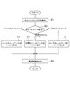
次に、上述した走行支援装置1の動作について、図3に示すフローチャートを参照しつつ説明する。
Next, operation | movement of the driving
本実施形態の走行支援装置1では、まず、ホイールベース長検出センサ11によって移動体Xのホイールベース長を検出する(S1)。続いて、ECU15において、ホイールベース長がショートホイールベースの場合(つまり、歩行モード時の場合)、減速制御マップにショートホイールベース用マップを設定する(S2→S3)。一方、検出したホイールベース長がロングホイールベースの場合(つまり、走行モード時の場合)、減速制御マップにロングホイールベース用マップを設定する(S2→S4)。
In the
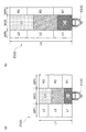
この減速制御マップは、移動体Xの前方において該移動体Xが走行する経路上の領域に設定された領域である障害物検出ゾーンZを含んでいる。具体的には、図4に示すように、障害物検出ゾーンZは、移動体Xが前方へ直進走行している場合、移動体Xの前方において矩形状に拡がる仮想領域としての障害物検出ゾーンZが設定される。 The deceleration control map includes an obstacle detection zone Z that is an area set in an area on a route on which the moving body X travels in front of the moving body X. Specifically, as shown in FIG. 4, the obstacle detection zone Z is an obstacle detection zone as a virtual area that expands in a rectangular shape in front of the moving body X when the moving body X travels straight ahead. Z is set.
ここでの障害物検出ゾーンZは、その領域が、幅方向に3分割と奥行き方向に3分割の9つのエリアC1,C2,C3,L1,L2,L3,R1,R2,R3に分割されて構成されている。具体的には、障害物検出ゾーンZには、中央に衝突監視エリアC1〜C3が設けられ、その左側に周辺監視エリアL1〜L3が設けられ、右側に周辺監視エリアR1〜R3が設けられている。 The obstacle detection zone Z here is divided into nine areas C1, C2, C3, L1, L2, L3, R1, R2, and R3, which are divided into three in the width direction and three in the depth direction. It is configured. Specifically, in the obstacle detection zone Z, collision monitoring areas C1 to C3 are provided at the center, peripheral monitoring areas L1 to L3 are provided on the left side, and peripheral monitoring areas R1 to R3 are provided on the right side. Yes.
なお、衝突監視エリアC1〜C3では、移動体Xの進路上に位置することから、障害物が存在すると移動体Xと衝突する可能性が高いため、十分な安全性の確保が必要とされる。周辺監視エリアL1〜L3,R1〜R3では、移動体Xの進路の側方に位置することから、障害物が存在すると移動体Xがその障害物の脇をすり抜けて走行するため、注意が必要とされる。 In the collision monitoring areas C1 to C3, since the vehicle is located on the path of the moving body X, it is highly likely that the vehicle will collide with the moving body X if there is an obstacle. Therefore, sufficient safety must be ensured. . In the peripheral monitoring areas L1 to L3 and R1 to R3, since the vehicle X is located on the side of the path of the mobile object X, if there is an obstacle, the mobile object X travels by the side of the obstacle, so care must be taken It is said.
衝突監視エリアC1〜C3の幅は、移動体Xの幅よりも広く、周辺監視エリアL1〜L3,R1〜R3に障害物が存在する場合にその脇を安全にすり抜けるための余裕分の幅を有している。周辺監視エリアL1〜L3,R1〜R3の幅は、衝突監視エリアC1〜C3の幅と同程度でもよいし、道路幅等に応じた幅等でもよい。また、障害物検出ゾーンZで最も移動体X寄りのエリアC1,L1,R1、次のエリアC2,L2,R3、最も移動体Xから離れたエリアC3,L3,R3の前後方向の長さ(以下、単に「長さ」という)のそれぞれは、同じでもよいし、移動体X寄り程短くする等長さを変えてもよい。 The widths of the collision monitoring areas C1 to C3 are wider than the width of the moving body X, and if there are obstacles in the surrounding monitoring areas L1 to L3 and R1 to R3, the width of the margin for safely passing through the side is provided. Have. The widths of the surrounding monitoring areas L1 to L3 and R1 to R3 may be the same as the widths of the collision monitoring areas C1 to C3, or may be a width according to the road width or the like. In the obstacle detection zone Z, the lengths in the front-rear direction of the areas C1, L1, R1 closest to the moving body X, the next areas C2, L2, R3, and the areas C3, L3, R3 farthest from the moving body X ( Hereinafter, each of them may be the same, or the length may be changed so as to be closer to the moving body X.
また、障害物検出ゾーンZにおいて衝突監視エリアC1〜C3と周辺監視エリアL1〜L3,R1〜R3との各長さは、同じでもよいし、衝突監視エリアC1〜C3の移動体X寄りを短くする等長さを変えてもよい。これらの幅や奥行き方向の長さについては、実験等によって設定されている。 Further, in the obstacle detection zone Z, the lengths of the collision monitoring areas C1 to C3 and the surrounding monitoring areas L1 to L3 and R1 to R3 may be the same, or the length of the collision monitoring areas C1 to C3 near the moving body X is shortened. The length may be changed. These widths and lengths in the depth direction are set by experiments and the like.
また、減速制御マップは、障害物検出ゾーンZの各エリアC1〜C3,L1〜L3,R1〜R3ごとにそれぞれ設定された最高速度(減速パターン)を含んでいる。障害物検出ゾーンZのうち最も移動体X寄りのエリアC1,L1,R1、次のエリアC2,L2,R3、最も移動体Xから離れたエリアC3,L3,R3の各最高速度は、移動体Xに近いほど低い最高速度が設定される。 The deceleration control map includes the maximum speed (deceleration pattern) set for each of the areas C1 to C3, L1 to L3, and R1 to R3 of the obstacle detection zone Z. In the obstacle detection zone Z, the maximum speeds of the areas C1, L1, R1 closest to the moving body X, the next areas C2, L2, R3, and the areas C3, L3, R3 farthest from the moving body X The closer to X, the lower the maximum speed is set.
さらに、衝突監視エリアC1〜C3と周辺監視エリアL1〜L3,R1〜R3とでは、衝突監視エリアC1〜C3の方が低い最高速度が設定される。これらの各エリアC1〜C3,L1〜L3,R1〜R3の最高速度については、各エリアC1〜C3,L1〜L3,R1〜R3までの距離や方向に応じて実験等によってそれぞれ設定されている。また、この最高速度は、移動体Xに適用される法律上の最高速度に応じて、少なくともそれ以下の速度がそれぞれ設定されている。 Further, in the collision monitoring areas C1 to C3 and the surrounding monitoring areas L1 to L3 and R1 to R3, the lower maximum speed is set in the collision monitoring areas C1 to C3. The maximum speeds of the areas C1 to C3, L1 to L3, and R1 to R3 are set by experiments or the like according to the distances and directions to the areas C1 to C3, L1 to L3, and R1 to R3. . In addition, the maximum speed is set to at least a speed lower than the maximum legal speed applied to the mobile object X.
ここで、通常、移動体Xの挙動特性はホイールベース長に応じて変化するため、移動体Xにとっては、ホイールベース長に応じて安全なエリアが変わる。すなわち、ホイールベース長が長いと、高速で旋回半径が大きくなって減速が困難であることから、減速開始が遅れないようにすべく、移動体Xの前方側の監視エリアが一層要される。また、ホイールベース長が短いと、低速で旋回半径が小さくなることから、小さな旋回時に対応すべく、移動体Xの前側方の監視エリアが一層要される。 Here, since the behavior characteristics of the moving body X usually change according to the wheel base length, for the moving body X, a safe area changes according to the wheel base length. That is, if the wheelbase length is long, the turning radius becomes large at high speed and deceleration is difficult, so that a monitoring area on the front side of the moving body X is further required so as to prevent the start of deceleration from being delayed. Further, if the wheel base length is short, the turning radius becomes small at a low speed. Therefore, a monitoring area on the front side of the moving body X is further required to cope with a small turning.
そこで、本実施形態では、ショートホイールベース用マップの障害物検出ゾーンZlとロングホイールベース用マップの障害物検出ゾーンZhとにおいては、そのエリアC1〜C3,L1〜L3,R1〜R3の幅が互いに異なっている。具体的には、障害物検出ゾーンZlにおける衝突監視エリアC1〜C3の幅WClが、障害物検出ゾーンZhにおける衝突監視エリアC1〜C3の幅WChよりも大きくなっている。また、障害物検出ゾーンZlにおける周辺監視エリアL1〜L3,R1〜R3の幅WPlが、障害物検出ゾーンZhにおける周辺監視エリアL1〜L3,R1〜R3の幅WPhよりも大きくなっている。 Therefore, in the present embodiment, the widths of the areas C1 to C3, L1 to L3, and R1 to R3 in the obstacle detection zone Zl of the short wheel base map and the obstacle detection zone Zh of the long wheel base map are as follows. They are different from each other. Specifically, the width WCl of the collision monitoring areas C1 to C3 in the obstacle detection zone Zl is larger than the width WCh of the collision monitoring areas C1 to C3 in the obstacle detection zone Zh. Further, the width WP1 of the peripheral monitoring areas L1 to L3 and R1 to R3 in the obstacle detection zone Zl is larger than the width WPh of the peripheral monitoring areas L1 to L3 and R1 to R3 in the obstacle detection zone Zh.
また、ショートホイールベース用マップの障害物検出ゾーンZlにおける長さLlと、ロングホイールベース用マップの障害物検出ゾーンZhにおける長さLhとが、互いに異なっている。ここでは、障害物検出ゾーンZhにおける長さLhが、障害物検出ゾーンZlにおける長さLlよりも大きくなっている。 The length Ll of the short wheel base map in the obstacle detection zone Zl is different from the length Lh of the long wheel base map in the obstacle detection zone Zh. Here, the length Lh in the obstacle detection zone Zh is larger than the length Ll in the obstacle detection zone Zl.
他方、検出したホイールベース長がショートホイールベースとロングホイールベースとの間の中間ホイールベースの場合(つまり、ホイールベース長の可変時の場合)、ショートホイールベース用マップとロングホイールベース用マップとを以下のように補完してなる中間ホイールベース用マップを、減速制御マップとして設定する(S2→S5)。 On the other hand, if the detected wheelbase length is an intermediate wheelbase between the short wheelbase and the long wheelbase (that is, when the wheelbase length is variable), the map for the short wheelbase and the map for the long wheelbase are An intermediate wheelbase map complemented as follows is set as a deceleration control map (S2 → S5).
すなわち、ホイールベース長Hは、ショートホイールベース長Hlとし、ロングホイールベース長Hhとしたとき、下式(1)で表せる。つまり、この下式(1)では、m=0のときのホイールベース長Hは、ショートホイールベース長Hlであり、m=1のときのホイールベース長Hは、ロングホイールベース長Hhを意味する。
H=Hl+m×(Hh−Hl) …(1)
但し、m:変数(0≦m≦1)。That is, when the wheel base length H is the short wheel base length Hl and the long wheel base length Hh, it can be expressed by the following equation (1). That is, in the following formula (1), the wheel base length H when m = 0 is the short wheel base length Hl, and the wheel base length H when m = 1 means the long wheel base length Hh. .
H = Hl + m × (Hh−Hl) (1)
Where m is a variable (0 ≦ m ≦ 1).
よって、中間ホイールベース用マップでは、例えば障害物検出ゾーンZの周辺監視エリアの幅WPについて、下式(2)に示すように、幅WPl及び幅WPhを線形補完し設定する。ちなみに、障害物検出ゾーンの長さ、衝突監視エリア、及び各エリアごとに設定された最高速度についても、下式(2)と同様にして線形補完し設定できる。
WP=WPl+m×(WPh−WPl) …(2)Therefore, in the intermediate wheel base map, for example, the width WPl and the width WPh are linearly complemented and set for the width WP of the periphery monitoring area of the obstacle detection zone Z as shown in the following equation (2). Incidentally, the length of the obstacle detection zone, the collision monitoring area, and the maximum speed set for each area can be set by linear interpolation in the same manner as in the following equation (2).
WP = WP1 + m × (WPh−WP1) (2)
続いて、ECU15において、設定された減速制御マップを用いて減速制御を行う(S6)。具体的には、レーザレーダ10から入力されたレーダ信号に基づいて、移動体Xの前方に障害物が存在するか否かを判定する。障害物が存在する場合、その障害物の移動体Xに対する相対位置を算出する。この相対位置に基づいて、障害物検出ゾーンZの複数のエリアC1〜C3,L1〜L3,R1〜R3のうち障害物が存在するエリア(以下、「障害物存在エリア」という)を検出する。
Subsequently, the
そして、検出した障害物存在エリアに設定された最高速度を、減速制御の目標値である目標最高速度として決定する。障害物が複数存在し、障害物存在エリアを複数検出する場合、目標最高速度が複数決定される場合がある。この場合、これら複数の目標最高速度のうち最も低いものを最終的な目標最高速度として決定する。なお、障害物が存在しない場合、目標最高速度を決定しない。この場合、常時、運転者によるアクセル操作に応じた速度となる。 Then, the maximum speed set in the detected obstacle existence area is determined as the target maximum speed that is the target value of the deceleration control. When there are a plurality of obstacles and a plurality of obstacle existence areas are detected, a plurality of target maximum speeds may be determined. In this case, the lowest one of the plurality of target maximum speeds is determined as the final target maximum speed. If no obstacle exists, the target maximum speed is not determined. In this case, the speed is always in accordance with the accelerator operation by the driver.
最後に、速度センサ12から入力された速度信号に基づいて、移動体Xの現在の車両速度が目標最高速度以下か否かを判定する。移動体Xの現在速度が目標最高速度より高いと判定した場合、移動体Xの速度が目標最高速度以下になるために必要な目標制動力を設定し、この目標制動力に基づいてモータ回生制御信号をインバータ13に送信し、さらに必要な場合にはブレーキ制御信号をブレーキアクチュエータ14に送信する。
Finally, based on the speed signal input from the
これにより、駆動モータ16が回生発電して回生制動力を発生すると共に、ブレーキ17が作動して制動力を発生する。その結果、移動体Xの車両速度が目標最高速度以下に低下されることとなる。なお、移動体Xの現在の車両速度が目標最高速度以下の場合、減速制御を行わずにそのまま処理を終了する。
As a result, the
以上において、ホイールベース長検出センサ11がホイールベース長情報取得部を構成し、レーザレーダ10が障害物情報取得部を構成し、ECU15が減速制御部を構成する。
In the above, the wheelbase
以上、本実施形態によれば、ホイールベース長に応じて減速制御が変更されるため、減速制御にホイールベース長を考慮することができ、減速制御が行われた際にホイールベース長に起因して移動体の挙動が乱れるのを抑制することができる。よって、ホイールベース長が可変な移動体Xにおいて、減速制御を適切に行うことが可能となる。すなわち、本実施形態では、車両姿勢に適した減速パターンで減速制御できるため、不要な減速制御を抑制しつつ必要な減速制御を行うことが可能となる。その結果、本実施形態にあっては、ホイールベース長が変化する移動体Xにおいて、進行方向を監視して衝突可能性を判断し減速する安全システムの減速パターンをホイールベース長に応じて変化できるものといえる。 As described above, according to the present embodiment, since the deceleration control is changed according to the wheel base length, the wheel base length can be taken into account for the deceleration control, which is caused by the wheel base length when the deceleration control is performed. Thus, it is possible to suppress the behavior of the moving body from being disturbed. Therefore, it is possible to appropriately perform the deceleration control in the moving body X having a variable wheelbase length. That is, in the present embodiment, the deceleration control can be performed with a deceleration pattern suitable for the vehicle posture, so that the necessary deceleration control can be performed while suppressing unnecessary deceleration control. As a result, in this embodiment, in the moving body X in which the wheel base length changes, the deceleration pattern of the safety system that monitors the traveling direction to determine the possibility of collision and decelerates can be changed according to the wheel base length. It can be said that.
また、本実施形態では、上述したように、ホイールベース長に応じて、減速度マップにおける障害物検出ゾーンZのエリアC1〜C3,L1〜L3,R1〜R3のエリア形状を変更している。具体的には、ホイールベース長が長くなるに従って、エリアC1〜C3,L1〜L3,R1〜R3を前方に拡張するように(長さが大きくなるように)変更している。また、ホイールベース長が短くなるに従って、エリアC1〜C3,L1〜L3,R1〜R3を幅方向に拡長するように(幅が大きくなるように)変更している。よって、ホイールベース長に関する移動体Xの上記挙動特性に適応した好適な減速制御が可能となり、減速制御を一層適切に行うことができる。さらに、移動体Xの挙動を安定化することができる。 In the present embodiment, as described above, the area shapes of the areas C1 to C3, L1 to L3, and R1 to R3 of the obstacle detection zone Z in the deceleration map are changed according to the wheelbase length. Specifically, the areas C1 to C3, L1 to L3, and R1 to R3 are changed to extend forward (increase in length) as the wheelbase length increases. Further, as the wheel base length becomes shorter, the areas C1 to C3, L1 to L3, and R1 to R3 are changed so as to expand in the width direction (so that the width becomes larger). Therefore, suitable deceleration control adapted to the behavior characteristics of the moving body X with respect to the wheelbase length is possible, and deceleration control can be performed more appropriately. Furthermore, the behavior of the moving body X can be stabilized.
なお、本実施形態では、上述したように、移動体Xの前方領域を分割してなるエリアC1〜C3,L1〜L3,R1〜R3ごとに最高速度を設定している。そして、移動体Xの車両速度が、障害物が存在するエリアの最高速度以上とならないように減速制御を行っている。よって、障害物が衝突監視エリアC1〜C3に存在する場合には、十分に低い速度まで減速でき、障害物に対して安全性を確保できる。一方、障害物が周辺監視エリアL1〜L3,R1〜R3に存在する場合には、衝突監視エリアC1〜C3ほど低い速度までの減速が要求されず、運転者は違和感を受けない。従って、障害物との接触を予防する上で、障害物位置に応じた適切な減速制御を容易に行うことができる。 In the present embodiment, as described above, the maximum speed is set for each of the areas C1 to C3, L1 to L3, and R1 to R3 obtained by dividing the front area of the moving body X. Then, deceleration control is performed so that the vehicle speed of the moving body X does not exceed the maximum speed of the area where the obstacle exists. Therefore, when an obstacle exists in the collision monitoring areas C1 to C3, the vehicle can be decelerated to a sufficiently low speed, and safety against the obstacle can be ensured. On the other hand, when the obstacle is present in the peripheral monitoring areas L1 to L3 and R1 to R3, deceleration to a lower speed than the collision monitoring areas C1 to C3 is not required, and the driver does not feel uncomfortable. Therefore, in preventing contact with an obstacle, appropriate deceleration control according to the obstacle position can be easily performed.
以上、本発明の好適な実施形態について説明したが、本発明は上記実施形態に限定されるものではない。例えば、上記実施形態では、1人乗りの電気車両を移動体としたが、移動体は限定されるものではなく、ホイールベース長が可変なものであればよい。 The preferred embodiment of the present invention has been described above, but the present invention is not limited to the above embodiment. For example, in the above-described embodiment, the single-seater electric vehicle is a moving body, but the moving body is not limited and any wheel base length may be used.
また、上記実施形態では、障害物検出ゾーンZにおいて各エリアC1〜C3,L1〜L3,R1〜R3ごとに最高速度を減速パターンとして設定しているが、減速度や減速度の変化割合等の他パラメータも減速パターンとして追加してもよい。 In the above embodiment, the maximum speed is set as the deceleration pattern for each of the areas C1 to C3, L1 to L3, and R1 to R3 in the obstacle detection zone Z. Other parameters may also be added as a deceleration pattern.
また、上記実施形態のホイールベース長検出センサ11は、ホイールベース長を可変するための可変用モータの回転数に基づいてホイールベース長を検出するものであるが、例えばストロークセンサを用いてホイールベース長を直接検出するものであってもよい。また、移動体Xの傾斜状態を検出することでホイールベース長を検出するものであってもよい。つまり、ホイールベース長検出センサ11は、ホイールベース長に関するホイールベース長情報を取得できればよい。
The wheel base
また、上記実施形態では、レーザレーダ10を用いて移動体Xの前方を監視したが、これに代えて若しくは加えて、その他の監視センサを用いて移動体Xの周囲(後方、側方)を監視してもよい。また、上記実施形態では、ホイールベース長に応じて、障害物検出ゾーンZのエリアC1〜C3,L1〜L3,R1〜R3を変更したが、エリアC1〜C3,L1〜L3,R1〜R3の少なくとも1つを変更すればよい。
In the above embodiment, the front of the moving body X is monitored using the
なお、移動体Xが前方へ旋回走行している場合には、障害物検出ゾーンZとして、移動体Xの前方において旋回進路(カーブR)に沿って前方側が屈曲するような四角形形状に拡がる障害物検出ゾーンが設定される。直進時の障害物検出ゾーンZの各エリアと旋回時の障害物検出ゾーンZの各エリアとでは、同じ最高速度がそれぞれ設定されてもよいし、旋回時の障害物検出ゾーンZの各エリアの方に低い最高速度がそれぞれ設定されてもよい。また、旋回時の障害物検出ゾーンZの各エリアには、カーブRが小さいほど低い最高速度がそれぞれ設定されてもよい。 When the moving body X is turning forward, the obstacle detection zone Z is an obstacle that expands into a rectangular shape in which the front side is bent along the turning path (curve R) in front of the moving body X. An object detection zone is set. The same maximum speed may be set for each area of the obstacle detection zone Z when going straight and each area of the obstacle detection zone Z when turning, or each area of the obstacle detection zone Z when turning A lower maximum speed may be set. Further, in each area of the obstacle detection zone Z at the time of turning, a lower maximum speed may be set as the curve R is smaller.
また、上記実施形態では、障害物検出ゾーンZにおいて9つのエリアC1〜C3,L1〜L3,R1〜R3を設定したが、エリア数は必要に応じて変更してもよい。さらに、エリアを設定せず、ある関数によって最高速度を設定してもよい。 In the above embodiment, nine areas C1 to C3, L1 to L3, and R1 to R3 are set in the obstacle detection zone Z. However, the number of areas may be changed as necessary. Further, the maximum speed may be set by a certain function without setting the area.
本発明によれば、ホイールベース長を変更可能な移動体において、減速制御を適切に行うことが可能となる。 ADVANTAGE OF THE INVENTION According to this invention, it becomes possible to perform deceleration control appropriately in the mobile body which can change wheelbase length.
1…走行支援装置、10…レーザレーダ(障害物情報取得部)、11…ホイールベース長検出センサ(ホイールベース長情報取得部)、15…ECU(減速制御部)、C1〜C3,L1〜L3,R1〜R3…エリア、X…移動体。
DESCRIPTION OF
Claims (3)
前記移動体の前記ホイールベース長に関するホイールベース長情報を取得するホイールベース長情報取得部と、
前記移動体の周辺の障害物に関する障害物情報を取得する障害物情報取得部と、
前記障害物情報取得部で取得した障害物情報に基づいて、前記移動体の減速制御を行う減速制御部と、を備え、
前記減速制御部は、前記ホイールベース長情報取得部で取得した前記ホイールベース長情報に応じて、前記減速制御を変更し、
前記減速制御部は、
前記移動体の周辺に設定された複数のエリアと前記複数のエリアごとに設定された減速パターンとを含む減速制御マップによって前記減速制御を行うものであって、
前記複数のエリアのうち前記障害物が存在する障害物存在エリアを前記障害物情報に基づき検出したとき、検出した前記障害物存在エリアにおける前記減速パターンで前記減速制御を行うと共に、
前記ホイールベース長情報に応じて、前記減速制御マップにおける前記複数のエリアを変更すること特徴とする走行支援装置。 A travel support device that is mounted on a mobile body having a variable wheelbase length and supports the travel of the mobile body,
A wheelbase length information acquisition unit for acquiring wheelbase length information related to the wheelbase length of the mobile body;
An obstacle information acquisition unit for acquiring obstacle information related to obstacles around the mobile body;
A deceleration control unit that performs deceleration control of the moving body based on the obstacle information acquired by the obstacle information acquisition unit,
The deceleration control unit changes the deceleration control according to the wheelbase length information acquired by the wheelbase length information acquisition unit ,
The deceleration control unit
The deceleration control is performed by a deceleration control map including a plurality of areas set around the moving body and a deceleration pattern set for each of the plurality of areas,
When the obstacle existing area where the obstacle is present is detected based on the obstacle information among the plurality of areas, the deceleration control in the detected deceleration pattern in the obstacle existing area is performed,
The driving support device according to claim 1, wherein the plurality of areas in the deceleration control map are changed according to the wheelbase length information .
前記減速制御部は、前記減速制御マップにおいて前記移動体の前方に設定された複数のエリアのうち少なくとも1つを、前記ホイールベース長が長くなるに従って前方に拡長するように、又は、前記ホイールベース長が短くなるに従って幅方向に拡長するように変更することを特徴とする請求項1記載の走行支援装置。 The obstacle information acquisition unit acquires obstacle information related to the obstacle in front of the moving object,
The deceleration control unit is configured to expand at least one of a plurality of areas set in front of the moving body in the deceleration control map forward as the wheel base length increases, or the wheel The driving support device according to claim 1 , wherein the driving support device is changed to expand in the width direction as the base length becomes shorter.
Applications Claiming Priority (1)
| Application Number | Priority Date | Filing Date | Title |
|---|---|---|---|
| PCT/JP2009/061021 WO2010146669A1 (en) | 2009-06-17 | 2009-06-17 | Driving assistance device |
Publications (2)
| Publication Number | Publication Date |
|---|---|
| JPWO2010146669A1 JPWO2010146669A1 (en) | 2012-11-29 |
| JP5316640B2 true JP5316640B2 (en) | 2013-10-16 |
Family
ID=43356007
Family Applications (1)
| Application Number | Title | Priority Date | Filing Date |
|---|---|---|---|
| JP2011519348A Expired - Fee Related JP5316640B2 (en) | 2009-06-17 | 2009-06-17 | Driving support device |
Country Status (4)
| Country | Link |
|---|---|
| US (1) | US8751128B2 (en) |
| JP (1) | JP5316640B2 (en) |
| CN (1) | CN102803030B (en) |
| WO (1) | WO2010146669A1 (en) |
Cited By (7)
| Publication number | Priority date | Publication date | Assignee | Title |
|---|---|---|---|---|
| US10343740B2 (en) | 2016-09-13 | 2019-07-09 | Toyota Jidosha Kabushiki Kaisha | Traveling apparatus |
| US10351202B2 (en) | 2016-09-07 | 2019-07-16 | Toyota Jidosha Kabushiki Kaisha | Traveling apparatus |
| US10450028B2 (en) | 2016-09-07 | 2019-10-22 | Toyota Jidosha Kabushiki Kaisha | Traveling apparatus |
| US10457342B2 (en) | 2016-07-08 | 2019-10-29 | Toyota Jidosha Kabushiki Kaisha | Traveling apparatus |
| US10640166B2 (en) | 2016-08-12 | 2020-05-05 | Toyota Jidosha Kabushiki Kaisha | Traveling apparatus |
| US10654362B2 (en) | 2016-09-13 | 2020-05-19 | Toyota Jidosha Kabushiki Kaisha | Traveling apparatus |
| US10745075B2 (en) | 2016-09-07 | 2020-08-18 | Toyota Jidosha Kabushiki Kaisha | Traveling apparatus |
Families Citing this family (10)
| Publication number | Priority date | Publication date | Assignee | Title |
|---|---|---|---|---|
| JP5375355B2 (en) * | 2009-06-17 | 2013-12-25 | トヨタ自動車株式会社 | Object detection device |
| CN105143027B (en) * | 2013-03-15 | 2019-05-31 | D·凯利 | three-wheeled vehicle |
| US10431099B2 (en) * | 2014-02-21 | 2019-10-01 | FLIR Belgium BVBA | Collision avoidance systems and methods |
| FR3034213B1 (en) | 2015-03-24 | 2018-06-01 | Insa De Rennes | METHOD FOR IMPROVED CORRECTION OF A TRACK IN A DEVICE FOR AIDING THE MOVEMENT OF PEOPLE |
| JP6790590B2 (en) * | 2016-08-26 | 2020-11-25 | トヨタ自動車株式会社 | Traveling device |
| JP6669009B2 (en) * | 2016-08-26 | 2020-03-18 | トヨタ自動車株式会社 | Traveling device |
| CN107640153B (en) * | 2017-09-21 | 2020-09-25 | 北京小米移动软件有限公司 | Micro sports car and its control method, device and storage medium |
| US12122474B2 (en) * | 2018-02-27 | 2024-10-22 | Honda Motor Co., Ltd. | Control device of a rideable mobile body including speed limiting unit for limiting target speed of the rideable mobile body according to positional relationship with virtual wall |
| JP7163152B2 (en) * | 2018-11-28 | 2022-10-31 | 京セラ株式会社 | IMAGE PROCESSING DEVICE, IMAGING DEVICE, MOBILE OBJECT, AND IMAGE PROCESSING METHOD |
| US12344104B2 (en) * | 2020-09-01 | 2025-07-01 | Battelle Memorial Institute | Electric vehicle systems and methods |
Citations (7)
| Publication number | Priority date | Publication date | Assignee | Title |
|---|---|---|---|---|
| JP2000159077A (en) * | 1998-11-30 | 2000-06-13 | Mazda Motor Corp | Vehicle control device |
| JP2001070357A (en) * | 1999-07-15 | 2001-03-21 | Daimlerchrysler Ag | Wheel suspension system for automobile |
| JP2002153515A (en) * | 2000-11-17 | 2002-05-28 | Kanto Auto Works Ltd | Wheelchair with vertically moving function |
| JP2005112300A (en) * | 2003-10-10 | 2005-04-28 | Toyota Motor Corp | vehicle |
| JP2005205980A (en) * | 2004-01-21 | 2005-08-04 | Nissan Motor Co Ltd | Vehicle travel control device |
| JP2009078733A (en) * | 2007-09-27 | 2009-04-16 | Hitachi Ltd | Driving support device |
| JP2009090829A (en) * | 2007-10-09 | 2009-04-30 | Advics:Kk | On-vehicle control device |
Family Cites Families (4)
| Publication number | Priority date | Publication date | Assignee | Title |
|---|---|---|---|---|
| DE10036276A1 (en) * | 2000-07-26 | 2002-02-07 | Daimler Chrysler Ag | Automatic braking and steering system for a vehicle |
| KR100534709B1 (en) * | 2003-12-30 | 2005-12-07 | 현대자동차주식회사 | Method and apparatus for controlling regenerative braking of electric vehicle |
| JP4532181B2 (en) * | 2004-06-24 | 2010-08-25 | 日産自動車株式会社 | VEHICLE DRIVE OPERATION ASSISTANCE DEVICE AND VEHICLE HAVING VEHICLE DRIVE OPERATION ASSISTANCE DEVICE |
| JP2008242544A (en) * | 2007-03-26 | 2008-10-09 | Hitachi Ltd | Collision avoidance apparatus and method |
-
2009
- 2009-06-17 JP JP2011519348A patent/JP5316640B2/en not_active Expired - Fee Related
- 2009-06-17 CN CN200980159864.5A patent/CN102803030B/en not_active Expired - Fee Related
- 2009-06-17 US US13/318,631 patent/US8751128B2/en not_active Expired - Fee Related
- 2009-06-17 WO PCT/JP2009/061021 patent/WO2010146669A1/en not_active Ceased
Patent Citations (7)
| Publication number | Priority date | Publication date | Assignee | Title |
|---|---|---|---|---|
| JP2000159077A (en) * | 1998-11-30 | 2000-06-13 | Mazda Motor Corp | Vehicle control device |
| JP2001070357A (en) * | 1999-07-15 | 2001-03-21 | Daimlerchrysler Ag | Wheel suspension system for automobile |
| JP2002153515A (en) * | 2000-11-17 | 2002-05-28 | Kanto Auto Works Ltd | Wheelchair with vertically moving function |
| JP2005112300A (en) * | 2003-10-10 | 2005-04-28 | Toyota Motor Corp | vehicle |
| JP2005205980A (en) * | 2004-01-21 | 2005-08-04 | Nissan Motor Co Ltd | Vehicle travel control device |
| JP2009078733A (en) * | 2007-09-27 | 2009-04-16 | Hitachi Ltd | Driving support device |
| JP2009090829A (en) * | 2007-10-09 | 2009-04-30 | Advics:Kk | On-vehicle control device |
Cited By (7)
| Publication number | Priority date | Publication date | Assignee | Title |
|---|---|---|---|---|
| US10457342B2 (en) | 2016-07-08 | 2019-10-29 | Toyota Jidosha Kabushiki Kaisha | Traveling apparatus |
| US10640166B2 (en) | 2016-08-12 | 2020-05-05 | Toyota Jidosha Kabushiki Kaisha | Traveling apparatus |
| US10351202B2 (en) | 2016-09-07 | 2019-07-16 | Toyota Jidosha Kabushiki Kaisha | Traveling apparatus |
| US10450028B2 (en) | 2016-09-07 | 2019-10-22 | Toyota Jidosha Kabushiki Kaisha | Traveling apparatus |
| US10745075B2 (en) | 2016-09-07 | 2020-08-18 | Toyota Jidosha Kabushiki Kaisha | Traveling apparatus |
| US10343740B2 (en) | 2016-09-13 | 2019-07-09 | Toyota Jidosha Kabushiki Kaisha | Traveling apparatus |
| US10654362B2 (en) | 2016-09-13 | 2020-05-19 | Toyota Jidosha Kabushiki Kaisha | Traveling apparatus |
Also Published As
| Publication number | Publication date |
|---|---|
| CN102803030B (en) | 2014-12-31 |
| JPWO2010146669A1 (en) | 2012-11-29 |
| CN102803030A (en) | 2012-11-28 |
| US20120101703A1 (en) | 2012-04-26 |
| US8751128B2 (en) | 2014-06-10 |
| WO2010146669A1 (en) | 2010-12-23 |
Similar Documents
| Publication | Publication Date | Title |
|---|---|---|
| JP5316640B2 (en) | Driving support device | |
| JP5338398B2 (en) | Driving support device | |
| JP5910754B2 (en) | Driving support device and driving support method | |
| CN106029477B (en) | Traveling vehicle and method for controlling traveling vehicle | |
| JP4020089B2 (en) | VEHICLE DRIVE OPERATION ASSISTANCE DEVICE AND VEHICLE WITH VEHICLE DRIVE OPERATION ASSISTANCE DEVICE | |
| JP5910634B2 (en) | Vehicle driving support system | |
| JP5598119B2 (en) | Motor vehicle | |
| JP2009067385A (en) | Vehicle notification device | |
| JP5065206B2 (en) | Mobile body, inverted mobile body, and control method thereof | |
| CN113423626A (en) | Method and control device for vehicle collision avoidance | |
| JP5233857B2 (en) | Collision safety device | |
| JP5321272B2 (en) | Driving support device | |
| KR101447811B1 (en) | Rollover protection control system and control method for forklift with speed and steering sensors | |
| JP5046027B2 (en) | Vehicle front bumper device | |
| JP2007008300A (en) | VEHICLE DRIVE OPERATION ASSISTANCE DEVICE AND VEHICLE WITH VEHICLE DRIVE OPERATION ASSISTANCE DEVICE | |
| JP6413919B2 (en) | Vehicle attitude control device | |
| CN117222566A (en) | Control device and control method for rider assistance system | |
| JP5347747B2 (en) | Obstacle recognition device | |
| JP5018039B2 (en) | vehicle | |
| JP2021041896A (en) | vehicle | |
| JP5375355B2 (en) | Object detection device | |
| JP2006062397A (en) | Vehicle behavior control device when contacting obstacles | |
| JP2015098232A (en) | Vehicle system | |
| JP6833329B2 (en) | Target route generator and steering control device | |
| KR101966459B1 (en) | Current Generating Suspension and Anti Dive Control Method thereby |
Legal Events
| Date | Code | Title | Description |
|---|---|---|---|
| A131 | Notification of reasons for refusal |
Free format text: JAPANESE INTERMEDIATE CODE: A131 Effective date: 20130108 |
|
| A521 | Request for written amendment filed |
Free format text: JAPANESE INTERMEDIATE CODE: A523 Effective date: 20130121 |
|
| TRDD | Decision of grant or rejection written | ||
| A01 | Written decision to grant a patent or to grant a registration (utility model) |
Free format text: JAPANESE INTERMEDIATE CODE: A01 Effective date: 20130611 |
|
| A61 | First payment of annual fees (during grant procedure) |
Free format text: JAPANESE INTERMEDIATE CODE: A61 Effective date: 20130624 |
|
| R151 | Written notification of patent or utility model registration |
Ref document number: 5316640 Country of ref document: JP Free format text: JAPANESE INTERMEDIATE CODE: R151 |
|
| LAPS | Cancellation because of no payment of annual fees |