JP5315943B2 - Electric power steering device - Google Patents
Electric power steering device Download PDFInfo
- Publication number
- JP5315943B2 JP5315943B2 JP2008289868A JP2008289868A JP5315943B2 JP 5315943 B2 JP5315943 B2 JP 5315943B2 JP 2008289868 A JP2008289868 A JP 2008289868A JP 2008289868 A JP2008289868 A JP 2008289868A JP 5315943 B2 JP5315943 B2 JP 5315943B2
- Authority
- JP
- Japan
- Prior art keywords
- bracket
- tube
- electric power
- power steering
- tilt
- Prior art date
- Legal status (The legal status is an assumption and is not a legal conclusion. Google has not performed a legal analysis and makes no representation as to the accuracy of the status listed.)
- Expired - Fee Related
Links
Images


Abstract
Description
本発明は電動パワーステアリング装置に関する。さらに詳しくは、アウターチューブとこのアウターチューブ内に圧入されたインナーチューブとの軸方向の摺動により衝撃吸収を行う電動パワーステアリング装置に関する。 The present invention relates to an electric power steering apparatus. More specifically, the present invention relates to an electric power steering device that absorbs impact by sliding in an axial direction between an outer tube and an inner tube press-fitted into the outer tube.
コラム型の電動パワーステアリング装置では、車両の衝突時の衝撃吸収を目的として、当該電動パワーステアリング装置を構成するチューブの収縮機能を備えているものがある。具体的には、アウターチューブ内にインナーチューブが圧入されており、衝突時には両チューブが軸方向に収縮しながら衝撃を吸収し、ある一定長さ以上のストロークを確保している。 Some column-type electric power steering apparatuses have a contraction function of a tube constituting the electric power steering apparatus for the purpose of absorbing shock at the time of a vehicle collision. Specifically, the inner tube is press-fitted into the outer tube, and both the tubes absorb the shock while contracting in the axial direction at the time of collision, and ensure a stroke of a certain length or more.
前記アウターチューブおよびインナーチューブのうち一方のチューブは、軸方向に移動しない固定チューブであり、他方のチューブは軸方向に移動し得る可動チューブである。そしてこの可動チューブは、通常時は、ブラケットを介して車体側に取り付けられているが、衝突により当該可動チューブが収縮する際、前記ブラケットが車体側から離脱することで可動チューブが所定のストロークだけ収縮できるようになっている。 One of the outer tube and the inner tube is a fixed tube that does not move in the axial direction, and the other tube is a movable tube that can move in the axial direction. The movable tube is normally attached to the vehicle body side via a bracket, but when the movable tube contracts due to a collision, the bracket is detached from the vehicle body side so that the movable tube has a predetermined stroke. It can be shrunk.
このように、ブラケットを車体側に離脱可能に取り付ける取付部材として、例えば特許文献1に記載のものがある。特許文献1に記載されている取付部材30は、図4に示されるように、当該取付部材30を車体側の部材に固定するための取付ボルト(図示せず)を挿通させる長孔31が形成された直方体形状の本体部32と、この本体部32の両側面それぞれに設けられた上下一対の支持部33とで構成されている。
Thus, there exists a thing of patent document 1 as an attachment member which attaches a bracket to a vehicle body side so that removal is possible, for example. As shown in FIG. 4, the
ブラケット34の両端部(図4では、一方の端部だけが図示されている)には、前記取付部材30を装着するために、ステアリングホイール側に開口された切欠部35が設けられている。また、ブラケット34には、切欠部35の両側に複数の小孔36が形成されている。一方、取付部材30の支持部33には、当該取付部材30をブラケット34に装着した際に、前記小孔36と位置が一致する複数の小孔37が形成されている。
At both end portions of the bracket 34 (only one end portion is shown in FIG. 4), a
前記取付部材30は、ブラケット34を上下一対の支持部33で挟むように当該ブラケット34の切欠部35に装着されている。その際、ブラケット34と取付部材30とは、それぞれに形成された小孔36と小孔37に合成樹脂を充填することによって形成されたピンにより一体化される。これにより、ドライバーとステアリングホイールとの衝突時に生じる衝撃が、前記ブラケット34が取り付けられたチューブから作用したとき、前記小孔36、37に充填された合成樹脂製のピンがせん断されることにより、前記ブラケット34が車体側から離脱する。
The
ところで、電動パワーステアリング装置がチルト動作可能なものである場合、前記可動チューブは、当該可動チューブに固定された固定ブラケットと、前記ブラケット(車体側に固定されるブラケット)とを貫通するチルトボルトをレバーにより回動操作することで、ブラケットに固定されたり、またはブラケットへの固定から解除されたりするように構成されている。すなわち、チルトボルトを一方向へ回動操作することで、固定ブラケットとブラケットとが締め付けられ、可動チューブはブラケットを介して車体側に固定され、この状態ではチルト操作を行うことができない。一方、チルトボルトを逆の方向へ回動操作すると、固定ブラケットとブラケットとの締め付けが解除され、可動チューブはチルト方向へ移動可能となる。この場合、ブラケットにはチルト方向に沿った長孔が形成されており、チルトボルトはこの長孔に沿ってチルト方向に移動する。 By the way, when the electric power steering apparatus is capable of tilting, the movable tube has a tilt bolt that penetrates the fixed bracket fixed to the movable tube and the bracket (the bracket fixed to the vehicle body side). It is configured to be fixed to the bracket or to be released from being fixed to the bracket by rotating the lever. That is, by rotating the tilt bolt in one direction, the fixed bracket and the bracket are tightened, and the movable tube is fixed to the vehicle body via the bracket. In this state, the tilt operation cannot be performed. On the other hand, when the tilt bolt is turned in the opposite direction, the fastening between the fixed bracket and the bracket is released, and the movable tube can move in the tilt direction. In this case, a long hole is formed in the bracket along the tilt direction, and the tilt bolt moves in the tilt direction along the long hole.
以上の構成を備えた電動パワーステアリング装置において、前述したチューブの所定長の収縮ストロークを確保できない場合がある。すなわち、電動パワーステアリング装置のチューブは、車種により程度は異なるが鉛直方向に対して斜めに配設されている。このような電動パワーステアリング装置のステアリングホイールにドライバーが衝突すると、前記チューブをチルト方向に跳ね上げるような力が作用する。通常の運転時には、レバーの回動操作により、チューブがチルト方向に移動できないようにロックされているが、チューブに対しチルト方向に衝撃力が加わると、このロックが強制的に解除されることがある。 In the electric power steering apparatus having the above-described configuration, there is a case where the above-described contraction stroke of the predetermined length of the tube cannot be secured. That is, the tube of the electric power steering apparatus is arranged obliquely with respect to the vertical direction, although the degree varies depending on the vehicle type. When the driver collides with the steering wheel of such an electric power steering apparatus, a force that raises the tube in the tilt direction acts. During normal operation, the tube is locked so that it cannot move in the tilt direction by turning the lever, but if an impact force is applied to the tube in the tilt direction, this lock may be forcibly released. is there.
一方、ドライバーのステアリングホイールへの衝突により、前記チルト方向の力とともに、チューブの軸方向への力も作用する。この軸方向の力によりチューブは収縮し、前記ブラケットが取付部材から離脱するが、このときに前記のようにチルトロックが解除されていると、ブラケットはフリーな状態になりチルトボルト廻りに回転する。ブラケットが回転すると、その先端部分が、チューブのロア側に配設されているハウジング(トルクセンサや減速機などを収容するハウジング)と干渉する結果、チューブの収縮が邪魔されて所定長の収縮ストロークを確保することができない。 On the other hand, due to the collision of the driver with the steering wheel, the force in the axial direction of the tube acts together with the force in the tilt direction. The tube contracts due to this axial force, and the bracket is detached from the mounting member. At this time, if the tilt lock is released as described above, the bracket becomes free and rotates around the tilt bolt. . When the bracket rotates, the tip part of the bracket interferes with the housing (housing that houses the torque sensor, speed reducer, etc.) arranged on the lower side of the tube. Can not be secured.
本発明は、このような事情に鑑みてなされたものであり、可動チューブに設けられた車体への固定用ブラケットの回転を防止して、当該可動チューブの所定長の収縮ストロークを確保することができる電動パワーステアリング装置を提供することを目的としている。 The present invention has been made in view of such circumstances, and can prevent the rotation of the bracket for fixing to the vehicle body provided on the movable tube and ensure the contraction stroke of the predetermined length of the movable tube. An object of the present invention is to provide an electric power steering device that can be used.
本発明の電動パワーステアリング装置は、アウターチューブとこのアウターチューブ内に圧入されたインナーチューブとの軸方向の摺動により衝撃吸収を行う電動パワーステアリング装置であって、
両チューブのうち可動側のチューブは、車体側に離脱可能に取り付けられる第1のブラケット、および、当該可動側のチューブに固定され且つ前記第1のブラケットに当接可能な第2のブラケットを備えており、
この第2のブラケットは、離脱した第1のブラケットの回転を防止する突起を有しており、
前記第1のブラケットは、中央の平板部と、この平板部の両側部から延設された側板部とを備えており、
前記第1のブラケットの一方の側部から保持板が斜め方向に延設されており、
この保持板と前記第1のブラケットの側板部との間に、側方から見てチルト方向に沿ったスリットが形成され、
このスリット内に前記突起を位置させることで、前記離脱した第1のブラケットの回転を防止するように構成したことを特徴としている。
The electric power steering device of the present invention is an electric power steering device that absorbs shock by sliding in the axial direction between the outer tube and the inner tube press-fitted into the outer tube,
Of the two tubes, the movable side tube includes a first bracket that is detachably attached to the vehicle body side, and a second bracket that is fixed to the movable side tube and that can contact the first bracket. And
The second bracket has a protrusion for preventing rotation of the detached first bracket,
The first bracket includes a central flat plate portion and side plate portions extended from both side portions of the flat plate portion,
A holding plate extends obliquely from one side of the first bracket;
Between the side plate portion of the holding plate and the first bracket, the slit along the tilt direction as viewed from the side is formed,
The projection is positioned in the slit so that the detached first bracket is prevented from rotating .
本発明の電動パワーステアリング装置は、可動側のチューブに固定された第2のブラケットが、離脱した第1のブラケットの回転を防止する突起を有しているので、衝撃により当該第1のブラケットが車体側から離脱するとともに、当該可動側のチューブのチルトロックが解除された場合であっても、前記第1のブラケットが回転してハウジングと干渉することが防止される。その結果、可動側のチューブの所定長の収縮ストロークを確保することができる。 In the electric power steering apparatus according to the present invention, the second bracket fixed to the movable side tube has a protrusion for preventing the rotation of the detached first bracket. The first bracket is prevented from rotating and interfering with the housing even when it is detached from the vehicle body side and the tilt lock of the movable tube is released. As a result, a contraction stroke of a predetermined length of the movable tube can be ensured.
前記突起が、第2のブラケットを構成する板材にプレス加工を施して形成される膨出部であるのが好ましい。この場合、部材点数を増加させることなく、また、専用の工程を設定することなく、前記突起を第2のブラケットの成形加工と同時に形成することができる。 It is preferable that the protrusion is a bulging portion formed by pressing a plate material constituting the second bracket. In this case, the protrusion can be formed simultaneously with the forming process of the second bracket without increasing the number of members and without setting a dedicated process.
本発明の電動パワーステアリング装置によれば、可動チューブに設けられた車体への固定用ブラケットの回転を防止して、当該可動チューブの所定長の収縮ストロークを確保することができる。 According to the electric power steering apparatus of the present invention, it is possible to prevent rotation of the bracket for fixing to the vehicle body provided on the movable tube, and to secure a predetermined contraction stroke of the movable tube.
以下、添付図面を参照しつつ、本発明の電動パワーステアリング装置の実施の形態を詳細に説明する。
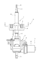
図1は、本発明の一実施の形態に係る電動パワーステアリング装置Sの要部の平面説明図であり、図2は図1に示される電動パワーステアリング装置のA−A線断面説明図である。電動パワーステアリング装置Sは、車室の内部において略上下に傾斜支持された筒型形状のステアリングコラム1と、このステアリングコラム1の内部に回転自在に支持されたステアリング軸2とを備えている。ステアリング軸2はステアリングコラム1を軸方向に貫通しており、当該ステアリング軸2の軸方向上端部2aには操舵部材であるステアリングホイール(図示せず)が固定される。また、ステアリングコラム1の下部に突出するステアリング軸2の下端部2bには、例えばラックピニオン式のステアリングギヤが連結され、ステアリングホイールの操舵によって図示しない車輪が操舵される。ステアリング軸2は、アウターチューブ11およびインナーチューブ12で構成されるチューブ内にて既知のスプラインなどによって、その軸方向に伸縮可能に連結されているシャフトを有している。
Embodiments of an electric power steering apparatus according to the present invention will be described below in detail with reference to the accompanying drawings.
FIG. 1 is a plan explanatory view of a main part of an electric power steering apparatus S according to an embodiment of the present invention, and FIG. 2 is a cross-sectional explanatory view taken along line AA of the electric power steering apparatus shown in FIG. . The electric power steering apparatus S includes a cylindrical steering column 1 that is inclined and supported substantially vertically in a passenger compartment, and a
ステアリングコラム1は、可動側チューブとしてのアウターチューブ11および固定側チューブとしてのインナーチューブ12が同軸的に摺動自在に嵌め合わされて構成される二分割タイプのものである。前記アウターチューブ11には、当該アウターチューブ11と自動車のダッシュボードなどに設けられた車体側部材3(図2〜3参照)とを一体的に固定するためのアッパー側のブラケットであるワンウェイブラケット4が設けられている。このワンウェイブラケット4は、取付部材5を介して前記車体側部材3に離脱可能に固定されている。この取付部材5は、当該取付部材5を車体側部材3に固定するための取付ボルト6を挿通させる孔7が形成された直方体形状の本体部8と、この本体部8の両側面それぞれに設けられた上下一対の支持部9とを備えている。ワンウェイブラケット4の両端部には、前記取付部材5に装着するために、ステアリングホイール側に開口された切欠部が設けられており、前記取付部材5の支持部9で当該切欠部の縁部を挟み込むようにしてワンウェイブラケット4が取付部材5に装着される。そして、図4に示される取付部材30と同様に、前記支持部9およびワンウェイブラケット4にそれぞれ形成された小孔9aおよび4aに合成樹脂を充填することで形成されたピン10によって、当該ワンウェイブラケット4と支持部9とが一体化されている。これにより、ドライバーとステアリングホイールとの衝突時に生じる衝撃が、前記ワンウェイブラケット4が取り付けられたアウターチューブ11から作用したとき、前記小孔9a、4aに充填された合成樹脂製のピン10がせん断されることにより、当該ワンウェイブラケット4が車体側から離脱する。
The steering column 1 is of a two-part type in which an
ステアリング軸2のロア側には、当該ステアリング軸2によって伝達されるトルク(操舵力)を検出するためのトルクセンサや、所望のトルクを得るための減速ギヤを有する減速機などを収容するハウジング13がインナーチューブ12と一体的に設けられている。このハウジング13は、操舵補助力を発生させるためのモータ14を支持している。なお、モータ14は、前記トルクセンサで検出されたトルクに基づきその回転動作が制御されて、その回転力を操舵補助力として前記ステアリングギヤに伝達する。これにより、ドライバーによるステアリングホイールの操舵動作を最適にアシストすることができる。
On the lower side of the
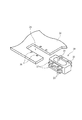
可動側のチューブであるアウターチューブ11は、車体側に離脱可能に取り付けられる第1のブラケットであるチューブブラケット16、および、当該アウターチューブ11に固定され且つ前記チューブブラケット16に当接可能な第2のブラケットである固定ブラケット17を備えている。チューブブラケット16は、前記ワンウェイブラケット4に溶接などにより固定される中央の平板部16aと、この平板部16aの両側部から延設された側板部16bとを備えた、断面略コの字の部材である。また、チューブブラケット16の一方の側部(後述するチルトレバー20が設けられる側と反対側の側部)には、電線ハーネスを固定するための保持板16cが斜め方向に延設されている。
固定ブラケット17も中央の平板部17aと、この平板部17aの両側部から延設された側板部17bとを備えた、断面略コの字の部材であり、前記チューブブラケット16の対向する側板部16bの内側において、前記側板部17bの先端部がアウターチューブ11の外周面に溶接などによって固定されている。
The
The fixed
前記チューブブラケット16および固定ブラケット17をチルトボルト18が貫通しており、このチルトボルト18の一端側であって当該チューブブラケット16の外側部分にチルトボルト18を回動操作するためのチルトアーム19が連結されている。また、このチルトアーム19の先端にはドライバーにより操作されるチルトレバー20が設けられている。チューブブラケット16の側板部16bには、図3に示されるように、チルト動作を許容するための長孔21が形成されている。そして、チルトボルト18に設けられた既知のカム機構により、チルトアーム19の回動操作によってチューブブラケット16と固定ブラケット17とが締め付けられたり、または、この締め付けが解除されたりするように構成されている。チューブブラケット16と固定ブラケット17とが締め付けられた状態では、前記ハウジング13を含む電動パワーステアリング装置S全体をチルト中心軸T(図1参照)を中心としてチルト方向(図1において略紙面貫通方向であり、図2において略上下方向)に移動させることができないが、この締め付けを解除した状態では電動パワーステアリング装置S全体をチルト方向に移動させることができる。このとき、チルトボルト18は、前記チューブブラケット16の側板部16bに形成された長孔21に沿って移動する。
A
図2〜3に示されるように、前記固定ブラケット17の両側板部17bの内一方の側板部17bの外側面の上部付近には、突起22が設けられている。この突起22は、チューブブラケット16の側板部16bと保持板16cとの間に形成された、側方から見てチルト方向に沿ったスリット23内に位置するように設けられている。また、突起22は、固定ブラケット17をプレス加工により成形する際に同時に形成された膨出部からなっている。この場合、部材点数を増加させることなく、また、専用の工程を設定することなく、突起22を固定ブラケット17の成形加工と同時に形成することができる。なお、本発明においては、スリット23の代わりに突起22に当接する当接部23aを備えていれば良く、チルトボルトよりも上側に突起22と当接部23aとが設けられていることが望ましい。
As shown in FIGS. 2 to 3, a
図3は、図1に示される電動パワーステアリング装置のブラケット(チューブブラケット16および固定ブラケット17)付近の側面説明図であり、(a)は衝撃吸収前の状態、(b)は衝撃吸収後の状態を示している。図3の(a)に示される通常の運転時は、チューブブラケット16により固定ブラケット17が締め付けられており、前述したハウジング13を含む電動パワーステアリング装置S全体のチルト方向への移動はできないようになっている。図3の(a)において、ΔLはアウターチューブ11とインナーチューブ12との間の吸収ストロークであり、ΔL´はワンウェイブラケット4とハウジング13との間の干渉距離である。通常、電動パワーステアリング装置Sを小型化して車両への搭載性を向上させると、ΔL´が小さくなりΔLを100%利用できなくなる。
この状態において、車両の衝突などによりドライバーがステアリングホイールに衝突して当該ステアリングホイールに衝撃力が加えられると、アウターチューブ11がチルト方向に跳ね上げられることがある。そうすると、前記カム機構により保持されていたチルトロックが強制的に解除される。また、ドライバーのステアリングホイールへの衝突によって、アウターチューブ11に軸方向の衝撃力も作用し、この衝撃力によってアウターチューブ11はロア側に収縮する(図3の(b)参照)。これにより、ワンウェイブラケット4もロア側に急激に移動し、前記合成樹脂製のピン10がせん断され、当該ワンウェイブラケット4は前記取付部材5から離脱する。このとき、前述したようにチルトロックが強制的に解除されているので、チューブブラケット16およびワンウェイブラケット4はチルトボルト18を中心にして回転しようとするが、突起22がチューブブラケット16のスリット23の内縁23aに当接するので、かかるチューブブラケット16およびワンウェイブラケット4の回転は阻止される。その結果、ワンウェイブラケット4の先端部が、例えば前記ハウジング13の角部13aと干渉するのを防ぐことができる。すなわち、ワンウェイブラケット4が回転することで当該ワンウェイブラケット4とハウジング13との干渉距離が吸収ストロークよりも小さくなるのを防ぐことができる。これにより、アウターチューブ11とインナーチューブ12との吸収ストロークを無駄なく使用することができ、ドライバーの安全性を向上させることができ、また、小型化と搭載性とを両立させることができる。また、突起22と当接部23aとがチルトボルト18よりも上側に設けられている場合には、ワンウェイブラケット4の回転量を更に低減できるので、ハウジング13の角部13aとの干渉を更に効果的に防ぐことができる。
3 is an explanatory side view of the vicinity of the brackets (
In this state, when the driver collides with the steering wheel due to a vehicle collision or the like and an impact force is applied to the steering wheel, the
なお、前記突起22は固定ブラケット17の両側板部17bのそれぞれの外側面に形成することができる。また、突起22としては、前述したプレス加工による膨出部に限定されるものではなく、例えば、側板部17bに略コの字状のスリットを形成し、ついでこのスリットで囲まれた部分を起立させることで得られる起立片を用いることができる。また、別体の突起体を側板部17bの外側面に固着することで突起を形成することもできる。
The
1 ステアリングコラム
2 ステアリング軸
3 車体側部材
4 ワンウェイブラケット
5 取付部材
11 アウターチューブ
12 インナーチューブ
13 ハウジング
16 チューブブラケット
17 固定ブラケット
18 チルトボルト
19 チルトアーム
20 チルトレバー
21 長孔
22 突起
23 スリット
23a 当接部(内縁)
30 取付部材
31 長孔
32 本体部
33 支持部
34 ブラケット
35 切欠部
36 小孔
37 小孔
S 電動パワーステアリング装置
DESCRIPTION OF SYMBOLS 1
30 mounting
Claims (3)
両チューブのうち可動側のチューブは、車体側に離脱可能に取り付けられる第1のブラケット、および、当該可動側のチューブに固定され且つ前記第1のブラケットに当接可能な第2のブラケットを備えており、
この第2のブラケットは、離脱した第1のブラケットの回転を防止する突起を有しており、
前記第1のブラケットは、中央の平板部と、この平板部の両側部から延設された側板部とを備えており、
前記第1のブラケットの一方の側部から保持板が斜め方向に延設されており、
この保持板と前記第1のブラケットの側板部との間に、側方から見てチルト方向に沿ったスリットが形成され、
このスリット内に前記突起を位置させることで、前記離脱した第1のブラケットの回転を防止するように構成したことを特徴とする電動パワーステアリング装置。 An electric power steering device that absorbs shock by sliding in an axial direction between an outer tube and an inner tube press-fitted into the outer tube,
Of the two tubes, the movable side tube includes a first bracket that is detachably attached to the vehicle body side, and a second bracket that is fixed to the movable side tube and that can contact the first bracket. And
The second bracket has a protrusion for preventing rotation of the detached first bracket,
The first bracket includes a central flat plate portion and side plate portions extended from both side portions of the flat plate portion,
A holding plate extends obliquely from one side of the first bracket;
Between the side plate portion of the holding plate and the first bracket, the slit along the tilt direction as viewed from the side is formed,
An electric power steering apparatus configured to prevent rotation of the detached first bracket by positioning the protrusion in the slit .
Priority Applications (1)
| Application Number | Priority Date | Filing Date | Title |
|---|---|---|---|
| JP2008289868A JP5315943B2 (en) | 2008-11-12 | 2008-11-12 | Electric power steering device |
Applications Claiming Priority (1)
| Application Number | Priority Date | Filing Date | Title |
|---|---|---|---|
| JP2008289868A JP5315943B2 (en) | 2008-11-12 | 2008-11-12 | Electric power steering device |
Publications (3)
| Publication Number | Publication Date |
|---|---|
| JP2010116008A JP2010116008A (en) | 2010-05-27 |
| JP2010116008A5 JP2010116008A5 (en) | 2012-10-04 |
| JP5315943B2 true JP5315943B2 (en) | 2013-10-16 |
Family
ID=42303945
Family Applications (1)
| Application Number | Title | Priority Date | Filing Date |
|---|---|---|---|
| JP2008289868A Expired - Fee Related JP5315943B2 (en) | 2008-11-12 | 2008-11-12 | Electric power steering device |
Country Status (1)
| Country | Link |
|---|---|
| JP (1) | JP5315943B2 (en) |
Families Citing this family (2)
| Publication number | Priority date | Publication date | Assignee | Title |
|---|---|---|---|---|
| US9096260B1 (en) | 2012-03-06 | 2015-08-04 | Nsk Ltd. | Impact absorbing steering apparatus |
| JP6403334B2 (en) * | 2015-03-09 | 2018-10-10 | 株式会社ジェイテクト | Steering device |
Family Cites Families (6)
| Publication number | Priority date | Publication date | Assignee | Title |
|---|---|---|---|---|
| JPH0443420Y2 (en) * | 1985-10-09 | 1992-10-14 | ||
| JPH0625076U (en) * | 1992-09-02 | 1994-04-05 | 三菱自動車エンジニアリング株式会社 | Steering device |
| JP3186445B2 (en) * | 1994-07-04 | 2001-07-11 | 日本精工株式会社 | Tilt type steering column device |
| JPH08295251A (en) * | 1995-04-26 | 1996-11-12 | Nippon Seiko Kk | Shock absorbing steering column unit |
| JP4395713B2 (en) * | 2003-08-28 | 2010-01-13 | 株式会社ジェイテクト | Tilt steering device |
| JP5125557B2 (en) * | 2008-02-04 | 2013-01-23 | 日本精工株式会社 | Steering device |
-
2008
- 2008-11-12 JP JP2008289868A patent/JP5315943B2/en not_active Expired - Fee Related
Also Published As
| Publication number | Publication date |
|---|---|
| JP2010116008A (en) | 2010-05-27 |
Similar Documents
| Publication | Publication Date | Title |
|---|---|---|
| US7401814B2 (en) | Steering device support structure | |
| KR101065895B1 (en) | Steering Column for Motor Vehicle Having Collision Energy Absorbing Apparatus | |
| US8651526B2 (en) | Steering apparatus | |
| JP6429077B2 (en) | Steering device | |
| JP2009061926A (en) | Steering column device | |
| JP2014051130A (en) | Steering device | |
| JP2017197032A (en) | Steering device | |
| JP5894888B2 (en) | Steering device | |
| JP5315943B2 (en) | Electric power steering device | |
| KR20160106807A (en) | Steering apparatus for vehicle | |
| JP2007314122A (en) | Electric power steering device | |
| JP2006224886A (en) | Steering device support structure | |
| JP2014073805A (en) | Rack-and-pinion type steering device for vehicle | |
| JP2008024170A (en) | Steering device | |
| JP2010076690A (en) | Steering column device | |
| JP4617916B2 (en) | Steering device support structure | |
| JP2006273047A (en) | Steering column device for vehicle | |
| JP2005104378A (en) | Impact absorbing structure for column shift device | |
| JP2005238894A (en) | Steering device | |
| JP6313997B2 (en) | Steering device | |
| JP6378897B2 (en) | Steering device | |
| JP5935495B2 (en) | Steering column shock absorbing mechanism and steering column device having the same | |
| JP2006137204A (en) | Steering device | |
| KR100700790B1 (en) | Steering column having ramp bracket | |
| WO2013176240A1 (en) | Impact absorbing steering device |
Legal Events
| Date | Code | Title | Description |
|---|---|---|---|
| A621 | Written request for application examination |
Free format text: JAPANESE INTERMEDIATE CODE: A621 Effective date: 20110927 |
|
| A521 | Written amendment |
Free format text: JAPANESE INTERMEDIATE CODE: A523 Effective date: 20120718 |
|
| A521 | Written amendment |
Free format text: JAPANESE INTERMEDIATE CODE: A523 Effective date: 20120822 |
|
| A977 | Report on retrieval |
Free format text: JAPANESE INTERMEDIATE CODE: A971007 Effective date: 20130123 |
|
| A131 | Notification of reasons for refusal |
Free format text: JAPANESE INTERMEDIATE CODE: A131 Effective date: 20130129 |
|
| A521 | Written amendment |
Free format text: JAPANESE INTERMEDIATE CODE: A523 Effective date: 20130226 |
|
| TRDD | Decision of grant or rejection written | ||
| A01 | Written decision to grant a patent or to grant a registration (utility model) |
Free format text: JAPANESE INTERMEDIATE CODE: A01 Effective date: 20130611 |
|
| A61 | First payment of annual fees (during grant procedure) |
Free format text: JAPANESE INTERMEDIATE CODE: A61 Effective date: 20130624 |
|
| R150 | Certificate of patent or registration of utility model |
Free format text: JAPANESE INTERMEDIATE CODE: R150 |
|
| LAPS | Cancellation because of no payment of annual fees |