JP5315357B2 - A device that serves a glass of wine or other liquid that may be affected by oxygen from a bottle. - Google Patents
A device that serves a glass of wine or other liquid that may be affected by oxygen from a bottle. Download PDFInfo
- Publication number
- JP5315357B2 JP5315357B2 JP2010535221A JP2010535221A JP5315357B2 JP 5315357 B2 JP5315357 B2 JP 5315357B2 JP 2010535221 A JP2010535221 A JP 2010535221A JP 2010535221 A JP2010535221 A JP 2010535221A JP 5315357 B2 JP5315357 B2 JP 5315357B2
- Authority
- JP
- Japan
- Prior art keywords
- bottle
- gas
- valve
- pressurized gas
- liquid
- Prior art date
- Legal status (The legal status is an assumption and is not a legal conclusion. Google has not performed a legal analysis and makes no representation as to the accuracy of the status listed.)
- Expired - Fee Related
Links
Images


Classifications
-
- B—PERFORMING OPERATIONS; TRANSPORTING
- B67—OPENING, CLOSING OR CLEANING BOTTLES, JARS OR SIMILAR CONTAINERS; LIQUID HANDLING
- B67D—DISPENSING, DELIVERING OR TRANSFERRING LIQUIDS, NOT OTHERWISE PROVIDED FOR
- B67D1/00—Apparatus or devices for dispensing beverages on draught
- B67D1/08—Details
- B67D1/0878—Safety, warning or controlling devices
- B67D1/0882—Devices for controlling the dispensing conditions
- B67D1/0885—Means for dispensing under specific atmospheric conditions, e.g. under inert gas
-
- B—PERFORMING OPERATIONS; TRANSPORTING
- B01—PHYSICAL OR CHEMICAL PROCESSES OR APPARATUS IN GENERAL
- B01F—MIXING, e.g. DISSOLVING, EMULSIFYING OR DISPERSING
- B01F25/00—Flow mixers; Mixers for falling materials, e.g. solid particles
- B01F25/30—Injector mixers
- B01F25/31—Injector mixers in conduits or tubes through which the main component flows
- B01F25/312—Injector mixers in conduits or tubes through which the main component flows with Venturi elements; Details thereof
-
- B—PERFORMING OPERATIONS; TRANSPORTING
- B01—PHYSICAL OR CHEMICAL PROCESSES OR APPARATUS IN GENERAL
- B01F—MIXING, e.g. DISSOLVING, EMULSIFYING OR DISPERSING
- B01F35/00—Accessories for mixers; Auxiliary operations or auxiliary devices; Parts or details of general application
- B01F35/71—Feed mechanisms
- B01F35/712—Feed mechanisms for feeding fluids
-
- B—PERFORMING OPERATIONS; TRANSPORTING
- B01—PHYSICAL OR CHEMICAL PROCESSES OR APPARATUS IN GENERAL
- B01F—MIXING, e.g. DISSOLVING, EMULSIFYING OR DISPERSING
- B01F35/00—Accessories for mixers; Auxiliary operations or auxiliary devices; Parts or details of general application
- B01F35/71—Feed mechanisms
- B01F35/717—Feed mechanisms characterised by the means for feeding the components to the mixer
- B01F35/71745—Feed mechanisms characterised by the means for feeding the components to the mixer using pneumatic pressure, overpressure, gas or air pressure in a closed receptacle or circuit system
-
- B—PERFORMING OPERATIONS; TRANSPORTING
- B67—OPENING, CLOSING OR CLEANING BOTTLES, JARS OR SIMILAR CONTAINERS; LIQUID HANDLING
- B67D—DISPENSING, DELIVERING OR TRANSFERRING LIQUIDS, NOT OTHERWISE PROVIDED FOR
- B67D1/00—Apparatus or devices for dispensing beverages on draught
- B67D1/04—Apparatus utilising compressed air or other gas acting directly or indirectly on beverages in storage containers
- B67D1/0412—Apparatus utilising compressed air or other gas acting directly or indirectly on beverages in storage containers the whole dispensing unit being fixed to the container
-
- B—PERFORMING OPERATIONS; TRANSPORTING
- B01—PHYSICAL OR CHEMICAL PROCESSES OR APPARATUS IN GENERAL
- B01F—MIXING, e.g. DISSOLVING, EMULSIFYING OR DISPERSING
- B01F2101/00—Mixing characterised by the nature of the mixed materials or by the application field
- B01F2101/06—Mixing of food ingredients
- B01F2101/16—Mixing wine or other alcoholic beverages; Mixing ingredients thereof
- B01F2101/17—Aeration of wine
-
- B—PERFORMING OPERATIONS; TRANSPORTING
- B67—OPENING, CLOSING OR CLEANING BOTTLES, JARS OR SIMILAR CONTAINERS; LIQUID HANDLING
- B67D—DISPENSING, DELIVERING OR TRANSFERRING LIQUIDS, NOT OTHERWISE PROVIDED FOR
- B67D1/00—Apparatus or devices for dispensing beverages on draught
- B67D1/04—Apparatus utilising compressed air or other gas acting directly or indirectly on beverages in storage containers
- B67D2001/0475—Type of gas or gas mixture used, other than pure CO2
- B67D2001/0481—Single inert gas, e.g. N2
Abstract
Description
本発明は、酸素の影響を受けるおそれのある液体をボトルからサーブ(給仕)し、またサーブ後に自動的にボトルからのサーブを停止することができる装置に関する。 The present invention relates to an apparatus capable of serving (serving) a liquid that may be affected by oxygen from a bottle and automatically stopping serving from the bottle after serving.
本発明は特に、ワイン醸造研究の分野で、高価なワインをボトルからグラスに注ぐサーブをすることに適しており、特に、ワインセラー、ワインショップ、バー、レストランなどでの使用に適する。 The invention is particularly suitable for serving expensive wines from bottles to glasses in the field of winemaking research, and in particular for use in wine cellars, wine shops, bars, restaurants and the like.
ボトルからワインをグラスにサーブし、サーブ後に自動でボトルからのサーブを停止することができる装置は存在する。しかし、他の液体と同様に、ワインは空気中に存在する酸素によって影響を受け易い。そのため、サーブする時とサーブした後にボトルを閉じる時の双方で、ボトルに侵入した空気がワインに影響することは不可避である。 There are devices that serve wine from a bottle into a glass and can automatically stop serving from the bottle after serving. However, like other liquids, wine is susceptible to oxygen present in the air. Therefore, it is inevitable that air that has entered the bottle affects the wine both when serving and when closing the bottle after serving.
この問題は、例えば窒素のような不活性ガスまたはアルゴンのような希ガスなどの酸素を含まない加圧ガスをボトル内に吹き込むことにより、細長送給チューブを経て、ボトルからワインを注ぎ出すことができる自動装置により解決してきた。ボトル内に徐々に吹き込むガスにより、ボトル内における増大する圧力により、細長送給チューブからワインを強制的に流出させる。 The problem is that the wine is poured out of the bottle through an elongate feed tube by blowing an oxygen-free pressurized gas such as an inert gas such as nitrogen or a rare gas such as argon. It has been solved by an automatic device that can. The gas that is gradually blown into the bottle forces the wine out of the elongated feed tube due to the increasing pressure in the bottle.
この装置は、加圧ガスを保有するシリンダと、ボトルネックに係合可能であり、ボトル内に加圧ガスを送給可能な細い入口チューブを有するガス供給接続部と、細い送給チューブと、シリンダからガス供給接続部にいたるガス流入ダクトとを備える。細長送給チューブは、開放時にワインを注ぎ出すためのタップを備えることができる。そのようなシステムは、ワインを注ぎ出すとき、および既に開封したボトル内にワインを保存するときの双方で空気がボトルに入り込むのを防ぐ。 The apparatus comprises a cylinder holding pressurized gas, a gas supply connection having a narrow inlet tube that can be engaged with a bottleneck and capable of feeding pressurized gas into the bottle, and a thin feeding tube; A gas inflow duct extending from the cylinder to the gas supply connection. The elongate feed tube can be provided with a tap for pouring wine when opened. Such a system prevents air from entering the bottle both when pouring wine and when storing the wine in an already opened bottle.
そのような装置の欠点は、第1ボトルが空になる前に、第1ボトルから第2ボトルに交換することが不可能であり、なぜなら、この交換は第1ボトルに空気を入れてしまうからであり、したがって、ボトル内のワインは短時間のみしか保存することが出来ない。 The disadvantage of such a device is that it is not possible to exchange from the first bottle to the second bottle before the first bottle is empty, because this exchange will inflate the first bottle. Therefore, the wine in the bottle can only be stored for a short time.
したがって、二つの異なるタイプのワインを順にサーブするために、既知タイプの装置を使用することは不可能である。特に、このような従来技術による、グラスに2つの異なる種類のワインをサーブする場合、ワインのボトル毎に1個の装置でサーブすることが必要であり、なぜなら各ボトルを、それが空になるまでずっと対応する装置上に取り付け続けなければならないからである。 It is therefore impossible to use a known type of device to serve two different types of wine in sequence. In particular, when serving two different types of wine in a glass according to such prior art, it is necessary to serve with one device for each bottle of wine, because each bottle is emptied. This is because it must continue to be mounted on the corresponding device.
これらの理由のために、従来技術の主な欠点は、異なるワイン用に多くの装置を並列的に設けなければならず、レストランおよびワインショップにおいて大きなスペースを必要とする。1つの装置は、約200×300×500mmの寸法を有するため、ワインボトルの数に比例する全体空間の負担は大きくなる。スペースだけでなくコストにも関連し、設備の全体コストは、ワインの異なるボトルの数に比例して増加する。このことにより、グラスで大衆に提供するワインの種類の数を限定することになる。 For these reasons, the main drawback of the prior art is that many devices have to be provided in parallel for different wines, requiring large spaces in restaurants and wine shops. Since one apparatus has a dimension of about 200 × 300 × 500 mm, the burden on the entire space is increased in proportion to the number of wine bottles. Related to cost as well as space, the overall cost of the equipment increases in proportion to the number of different bottles of wine. This limits the number of wine types offered to the masses in a glass.
本発明の目的は、ボトルからワインまたは酸素の影響を受けるおそれのある他の液体をグラスにサーブするためのサーブ装置であって、部分的に使用した第1ボトルから別のボトルに交換し、このとき第1ボトル内のワインを確実に好適な状態で保存できるサーブ装置を得るにある。 An object of the present invention is a serving device for serving wine or other liquids that may be affected by oxygen from a bottle into a glass, replacing the partially used first bottle with another bottle, At this time, it is to obtain a serve device that can reliably store the wine in the first bottle in a suitable state.
本発明の別の目的は、ワインまたは酸素の影響を受けるおそれのある他の液体をサーブするサーブ装置であって、異なるワインのサーブを単独の装置で行うことができるサーブ装置を得るにある。 Another object of the present invention is to provide a serve device that serves wine or other liquids that may be affected by oxygen, and that can serve different wines in a single device.
本発明のさらなる態様は、複数個のボトルから一種類以上のワインを酸素がない状態でサーブするサーブ装置であって、取り扱いが面倒ではなく、かつあまり高価でないサーブ装置を得るにある。 A further aspect of the present invention is to provide a serve device for serving one or more types of wine from a plurality of bottles in a state free of oxygen, which is not troublesome and is not very expensive.
これらおよび他の目的は、既に開封したボトルから酸素の影響を受けるおそれのある液体、特にワインを、前記ボトル内に加圧ガスを吹き込むことにより、酸素なしにサーブするサーブ装置であって、前記ボトルは口部にボトルネックを有するものとした、該サーブ装置によって達成することができ、このサーブ装置は、前記ボトルネックの口部に固定できる通常閉じている常閉の釈放可能締結部材と、
‐前記加圧ガスを受け入れてボトル内に送るよう構成し、加圧ガス供給源に緊密接続する接続手段と、
‐前記釈放可能締結部材を収容するよう構成した固定係合部材と、
‐前記固定係合部材に関連して設けたガス送給バルブと、
‐前記ガス送給バルブと空気回路的に接続した加圧ガス供給装置と、
‐前記ガス送給バルブと前記釈放可能締結部材との間の緊密係合を提供する緊密係合手段と、を備え、
前記固定係合部材は、
‐前記釈放可能締結部材の存在を検知し、前記釈放可能締結部材の存在/不在に応じて、前記送給バルブの操作を、それぞれ許可/阻止するセンサを有し、
前記釈放可能締結部材は、
‐前記加圧ガスを受け入れて前記ボトル内に送るよう構成し、加圧ガス供給源に緊密接続する接続手段と、
‐ガスを送給する際に液体を注ぎ出すサーブ手段であって、ボトルの内側底部領域と液圧回路的に接続する、該サーブ手段と、
‐前記加圧ガス供給源から引き離したとき、前記ボトルを閉鎖状態に維持し、ボトル内の加圧ガスを維持するボトル閉止手段と、を有し、
前記ボトル閉止手段は、
‐締結手段により前記ボトルの口部に固定することができる閉鎖部材であって、前記閉鎖部材を通過して前記ボトル内に導入する加圧ガスの流入ダクト、前記ボトルの内側底部領域から液体を送出して外部にサーブするための液体送給ダクト、および前記ボトルネックに緊密に係合可能な円筒形部分を有する閉鎖部材と、
‐流入ダクトに設けた、前記加圧ガスを供給するときに開き、またそれ以外全ての場合に閉じるよう構成した逆止バルブと、
‐前記液体送給ダクトに設けた逆止バルブと、を有する。
These and other objects are serving devices that serve oxygen-free liquids, especially wine, from bottles that have already been opened by blowing pressurized gas into the bottles without oxygen. bottle was assumed to have a bottleneck in the mouth, can be achieved by the serving device, the Saab device includes a releasable fastening member normally closed is closed normally be secured to the mouth of the bottle neck,
-Connecting means configured to receive said pressurized gas and send it into the bottle, intimately connected to a source of pressurized gas;
A fixed engagement member configured to receive the releasable fastening member;
-A gas feed valve provided in connection with the fixed engagement member;
-A pressurized gas supply device connected in air circuit with the gas delivery valve;
-Tight engagement means for providing a close engagement between the gas delivery valve and the releasable fastening member;
The fixed engagement member is
-A sensor for detecting the presence of the releasable fastening member and allowing / blocking the operation of the feeding valve according to the presence / absence of the releaseable fastening member,
The releaseable fastening member is:
-A connecting means adapted to receive said pressurized gas and deliver it into said bottle, and to be intimately connected to a source of pressurized gas;
A serve means for pouring liquid when delivering gas, said serve means being connected in hydraulic circuit with the inner bottom region of the bottle;
-A bottle closing means for maintaining the bottle closed when pulled away from the pressurized gas supply source and maintaining the pressurized gas in the bottle ;
The bottle closing means is
-A closing member that can be fixed to the mouth of the bottle by a fastening means, wherein an inflow duct for a pressurized gas that passes through the closing member and is introduced into the bottle, the liquid from the inner bottom region of the bottle A liquid delivery duct for delivering and serving to the outside, and a closure member having a cylindrical portion that can be tightly engaged with the bottleneck;
-A check valve provided in the inflow duct that is configured to open when supplying the pressurized gas and to close in all other cases;
A check valve provided in the liquid supply duct;
好適には、前記ガス送給バルブは、押しボタンまたは同等の操作装置により操作する。 Preferably, the gas delivery valve is operated by a push button or equivalent operating device.
好適には、前記ガス送給バルブは、前記押しボタンにより操作する機械式バルブ、前記押しボタンにより操作するソレノイドバルブからなるグループから選択する。 Preferably, the gas supply valve is selected from the group consisting of a mechanical valve operated by the push button and a solenoid valve operated by the push button.
好適には、前記緊密係合手段は、該緊密係合手段の表面に緊密に整合するよう構成した薄膜であって、送給されたガスの圧力で形状が変化して前記緊密係合を確実に行う薄膜と、 Preferably, the tight engagement means is a thin film configured to closely match a surface of the tight engagement means, and the shape is changed by the pressure of the supplied gas to ensure the tight engagement. A thin film to be
前記釈放可能締結部材に向かってガスが流れるようになる前に前記薄膜の変形を可能にするよう設けた較正可能なストッパと、 A calibratable stopper provided to allow deformation of the membrane before gas flows toward the releasable fastening member;
を有する構成とする。It is set as the structure which has.
好適には、前記固定係合部材はガイド部材とし、前記釈放可能締結部材は前記ガイド部材に摺動可能に係合するフランジを有し、前記フランジは、前記釈放可能締結部材が前記送給バルブに十分に整列するまで摺動可能とする。 Preferably, the fixed engagement member is a guide member, the releasable fastening member has a flange slidably engaged with the guide member, and the flange includes the releaseable fastening member which is the feed valve. It can be slid until it is fully aligned with.
好適には、前記加圧ガス供給装置は、所定の圧力値以下に前記ボトル内のガス圧を制限するよう構成した安全圧力スイッチを備える。 Preferably, before Symbol pressurized gas supply device comprises a safety pressure switch that is configured to limit the gas pressure in the bottle below a predetermined pressure value.
好適には、前記加圧ガス供給装置は、 Preferably, the pressurized gas supply device comprises:
‐ガスシリンダ、-Gas cylinders,
‐ガス供給ネットワーク-Gas supply network
よりなるグループから選択する。Select from the group consisting of
好適には、前記ガスシリンダは1.5リットルより少ない容積を有する。 Preferably, the gas cylinder has a volume of less than 1.5 liters.
好適には、前記ガスシリンダは減圧バルブを備える。 Preferably, the gas cylinder includes a pressure reducing valve.
好適には、前記加圧ガスは、ワインを酸化させないよう、酸素を含まない不活性ガスおよび/または希ガスとし、特に、 Preferably, the pressurized gas is an inert gas and / or a noble gas containing no oxygen so as not to oxidize the wine,
‐窒素、-nitrogen,
‐アルゴン-argon
よりなるグループから選択する。Select from the group consisting of
好適には、異なるワイン用にそれぞれ対応するボトルおよび結合表面のため、複数の固定係合手段を備える構成とする。 Preferably, a plurality of fixed engagement means are provided for bottles and binding surfaces respectively corresponding to different wines.
好適には、前記サーブ手段は、前記液体送給ダクトと液圧的に接続し、 Preferably, the serve means is hydraulically connected to the liquid feed duct,
‐液体を自由に送出させる細いチューブ、-A thin tube that allows liquid to flow freely,
‐開閉バルブを有して液体を送出させる細いチューブ、-A thin tube with an open / close valve to deliver liquid,
‐空気/液体混合器-Air / liquid mixer
からなるグループから選択する。Select from the group consisting of
好適には、前記空気/液体混合器は、ベンチュリー作用により空気を吸引し、ワインを酸化させる、狭い横断面部分を有する中空体を備える構成とする。 Preferably, the air / liquid mixer includes a hollow body having a narrow cross-sectional portion that sucks air by a venturi action and oxidizes wine.
好適には、前記接続手段は、前記加圧ガス供給源に属する固定係合部材に係合可能な結合面を有し、前記結合面が前記固定係合部材に係合するとき、前記加圧ガス供給源が前記流入ダクトと気密に緊密接続する。 Preferably, the connection means has a coupling surface engageable with a fixed engagement member belonging to the pressurized gas supply source, and when the coupling surface engages with the fixed engagement member, the pressurization is performed. A gas supply source is tightly connected to the inflow duct.
好適には、 Preferably,
‐バヨネット連結、-Bayonet consolidation,
‐ねじ連結、-Screw connection,
‐スナップ連結、-Snap connection,
‐スライド連結、-Slide connection,
‐磁気連結、-Magnetic coupling,
からなるグループから選択した連結により、前記結合面を、前記固定係合部材に係合可能な構成とする。The coupling surface is configured to be engageable with the fixed engagement member by connection selected from the group consisting of:
好適には、前記ボトルの口部に前記閉鎖部材を固定する前記締結手段は、前記閉鎖部材が係合できるブッシュを備え、前記ブッシュは、前記ボトルネックから突出するボトル端縁に固定することができるフック部分を有する。 Preferably, the fastening means for fixing the closing member to the mouth portion of the bottle includes a bush with which the closing member can be engaged, and the bush is fixed to a bottle edge protruding from the bottle neck. It has a hook part that can.
好適には、前記サーブ手段は、前記液体送給ダクトと液圧回路的に接続し、前記液体送給ダクトは開閉バルブを備え、該開閉バルブは、 Preferably, the serve means is connected to the liquid supply duct in a hydraulic circuit, and the liquid supply duct includes an open / close valve,
‐押しボタンタップ、-Push button tap,
‐ハンドルタップ、-Handle tap,
‐ワインをサーブするために前記ボトルを開き、また前記ボトル内に空気が逆流することを防ぐ逆止バルブ、-A check valve that opens the bottle to serve wine and prevents air from flowing back into the bottle;
‐ソレノイドバルブ、-Solenoid valve,
からなるグループから選択する。Select from the group consisting of
好適には、前記ボトル内のガス圧が閾値を越えることを防ぐよう構成した安全バルブを有する。 Preferably, there is a safety valve configured to prevent the gas pressure in the bottle from exceeding a threshold.
本発明は、非限定的な実施形態の例を、添付図面につき以下に詳細に説明することにより、明らかとなるであろう。 The invention will become apparent from the following detailed description of an example of a non-limiting embodiment with reference to the accompanying drawings.
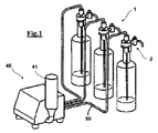
図1につき説明すると、例として本発明により酸素に触れることなく液体をサーブする装置の斜視図を示す。特に、図示のように3個の送給出口を設け、各送給出口は、固定係合部材1、およびボトル30に固定できる釈放可能締結部材2とにより形成する。
Referring to FIG. 1, by way of example, a perspective view of an apparatus for serving liquid without touching oxygen according to the present invention is shown. In particular, three supply outlets are provided as shown, and each supply outlet is formed by a fixed
サーブ装置の図示した実施例は3個の個別ボトル用に3個の接続部を有するが、実施形態としては、単独の釈放可能締結部材また、他の個数の釈放可能締結部材を有する実施形態を除外するものではない。 The illustrated embodiment of the serve device has three connections for three individual bottles, but embodiments include a single releaseable fastening member or other number of releaseable fastening members. It is not excluded.
サーブ装置は、不活性ガス、例えば窒素またはアルゴンなどの酸素なしの加圧ガス供給源を備え、例えばガス供給装置40に接続するシリンダ41を有し、その操作を図2の液圧回路図で説明する。ガス供給装置40により、加圧ガスを分配して、ボトル30内に、ダクト50を通過させて供給する。
The serve device has a pressurized gas supply source without an inert gas such as nitrogen or argon, and has a
図3,4および5はより詳細に、本発明による、固定係合部材1(ダクト50に対する接続の仕方は示さない)、および釈放可能締結部材2を示す。
3, 4 and 5 show in more detail the fixed engagement member 1 (not shown how to connect to the duct 50) and the
図2は、サーブ装置の液圧回路図を示し、この液圧回路は、順次に、不活性ガスを収容するシリンダ41、減圧バルブ42、シリンダ41内のガス不足を表示する圧力スイッチ43、送給ガスに適するソレノイドバルブ44、最大閾値以下に圧力を制限するよう構成した安全バルブ45、連続してソレノイドバルブ44が開くのを防ぐガスタンク46、ソレノイドバルブを操作することによりボトル30内の圧力を一定に維持するよう構成した圧力スイッチ47、および最後に、固定係合部材1およびボトル30、特にワインボトルに固定した釈放可能締結部材2によって形成したサーブ装置と、を備える。
FIG. 2 shows a hydraulic circuit diagram of the serve device. This hydraulic circuit sequentially includes a
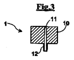
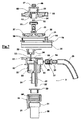
図3は、固定係合部材1の断面を示し、図示しない仕方でチューブ50に装着するチャネル11が横断するブロック10を備える。例えば、チャネル11はコレクタ12で終端させ、このコレクタ12は、釈放可能締結部材2に設けた対応する孔23(図4参照)と緊密に係合できるようにする。当然ながら、固定係合部材1と釈放可能締結部材2との間における結合部を有する種々の実施形態もあり得る。
FIG. 3 shows a cross-section of the fixed
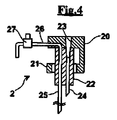
図4は、ボトル30(図5参照)の口部に動作可能に固定できる釈放可能締結部材2の断面図を示す。釈放可能締結部材2は、ボトルネックから突出するリングに結合する手段21を有する締結素子20を備える。さらに、釈放可能締結部材2は、ボトルネックの口部に圧入して緊密な接続を確実に生ずるよう構成した円筒部分22を備える。釈放可能締結部材2には、短い長さでボトル内に達する加圧ガスの流入ダクト24を横断させ、ボトル内に含まれるワインに泡を発生しないようにする。釈放可能締結部材2には、さらに、流入ダクト24より長くボトルの内側底部領域に達する送給ダクト25を横断させる。常閉のサーブバルブ27、例えば押しボタンを、送給ダクト25から連続するサーブダクト26に取り付ける。
FIG. 4 shows a cross-sectional view of the
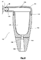
図5は、酸素に触れることなくワインを分配できるよう、このような釈放可能締結部材2および固定係合部材1を動作可能に結合した状態を示す。図示のように、最初にボトルを開封した後に、ボトル30を釈放可能締結部材2により閉鎖し、閉じたワインボトルのように、冷蔵庫内で、例えば横倒しにしたり、直立させたりして使用準備をしてしまうことができる。内部に不活性ガスが存在することによって、長期間のワインの保存を可能にし、ボトル開封後に10〜15日経過しても感覚刺激特性を損なわない。
FIG. 5 shows a state in which such a
ワインを再びサーブする時、このようなサーブ装置の作動は、ボトル内へ不活性加圧ガスを注入するステップを行う。加圧ガスはボトル内に含まれるワインを押圧し、これにより、送給ダクト25内で上昇させ、常閉サーブバルブ27を装備したサーブダクト26(図5参照)を経てボトルから流出させる。実際、釈放可能締結部材2を連結したボトル30が、係合部材1に結合した釈放可能締結部材2を有するとき、バルブ27開放の際に、ボトル内に空気が侵入することなくワインを供給する。第1ボトルのワインを別のワインを含む第2ボトルに交換して、グラスにサーブするとき、固定係合部材1から分離した釈放可能締結部材2とともに第1ボトルを単に外すだけでよく、固定係合部材1を第2ボトルに結合する。釈放可能締結部材2を固定係合部材1から分離するとき、ダクト24に取り付けた、図5には図示していない適切な逆止バルブにより、ボトル内に先に注入した加圧ガスの出口をブロックし、同時に空気の逆流をブロックし、ボトルに含まれるワインまたは他の液体を最も好ましい状態で保存する。
When serving the wine again, the operation of such a serving device involves injecting an inert pressurized gas into the bottle. The pressurized gas presses the wine contained in the bottle, and thereby rises in the
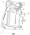
本発明の好適な実施形態を図6に示し、互いに動作可能に結合した固定係合部材101および釈放可能締結部材102を示す。特に、固定係合部材101はバルブユニット80と、好適にはガイド70である連結部材とを備えるとともに、釈放可能締結部材102は、例えば固定係合部材101のガイド70に係合するフランジ61を有する継手部材60、およびボトル30に対する締結素子20により構成する。
A preferred embodiment of the present invention is shown in FIG. 6 and shows a fixed
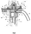
図6は、さらに、ネジ82によりガイド70に固定し、また部分的に見えているソレノイドバルブ47を継手部57で固定した、バルブユニット80を示す。バルブユニット80は可動素子53を収容し、この可動素子はハウジング84(図7参照)であるときに、ガスのための環状チャネル81を形成する形状およびサイズとする。
FIG. 6 further shows a
可動素子53において、そのハウジング54(図7参照)内に、バネ負荷ストッパ39を対応のシール52で取り付ける。
In the
さらに、薄膜38をガイド70に挿入して、把持部材36によりブロックする。薄膜38は、チャネル81から到来するガス圧下で変形可能であり、これにより封止リップ37が継手部材60に圧着する。
Further, the
ガイド70と継手部材60との間の連結は、ガイド70の方向にフランジ61を差し入れることにより得る(図8参照)。この連結により、装置に組み込んだリードスイッチ85、および継手部材に組み込んだ磁性体86により、信号を発生する。
The connection between the
継手部材60(図6参照)には、以下のもの、すなわち、
‐第1ハウジング89(図7参照)、
‐ハウジング89内に設けたバルブ本体34、
‐チャンバ83にガスを流入させるバルブ本体34内のチェックバルブ32、
‐第2ハウジング90(図7参照)、
‐常閉のサーブバルブ27であって、送給ダクト26に緊密接続するためにシール29および2個のOリング28とともにハウジング90に挿入したサーブバルブ27、
‐ガスの流入ダクト24、
‐ワインの送給ダクト25であって、ボトルの内側底部まで下方に延在するよう構成した図示しない細長チューブに接続する首端部25′を有する送給ダクト25、
が存在する。
The joint member 60 (see FIG. 6) includes the following:
The first housing 89 (see FIG. 7),
The
The
The second housing 90 (see FIG. 7),
A normally closed serve
-
A
Exists.
継手部材60の外側部分にねじ山88を設け、釈放可能締結部材の継手部材60を締結素子20に連結する機能を持たせ、当該締結素子20にはねじ山に対応する内側リップ88′を設け、この内側リップ88′は、強制挿入のため可撓性かつ円形形状にする、またはねじ連結のため螺旋形状にすることができる。
A
ボトルネックの口部に配置すべき封止ブッシュ22を設け、ガス圧下でボトル内に含まれる液体を密封するとともに、フック21を締結素子20に設け、ボトル30の首部から突出する突起リング端縁31に係合させる。
A sealing
図7は、好適な実施形態における固定係合部材1、および釈放可能締結部材2の分解図である。
FIG. 7 is an exploded view of the fixed
この図面においては、以下のもの、すなわち、可動ユニット53のためのハウジング84を有するバルブユニット80、ガスのためのダクト56、ソレノイドバルブ47に連結する継手部57(図6参照)、および120゜毎に配置した3個のハウジング5、を示す。特に、ハウジング55は、孔35を有する突出部94に整合し、ねじ82(図6参照)によりガイド70をバルブユニット80に固定する。
In this figure, the following: a
図7は、さらにまた、可動素子53とストッパ39との間に取り付けたシール52、ストッパ39に連結した保護カーター51、ガイド部材内の把持素子36により挿入する変形可能薄膜38を示す。
FIG. 7 further shows the
ガイド70は、特にC字状輪郭部35を設け、継手部材60(図8参照)に属する補完形状のフランジ61を受け入れて、装置2全体をサーブ装置4に連結することができるようにする。
The
図7は、さらに、ハウジング89内に装着したバルブ本体34を示し、ハウジング89には、チャンバ83内への流入を逆止バルブ32によって制御されるガスを送給する孔33を形成する。継手部材60には、さらにまた、ガス流入ダクト24、送給ダクト25、バルブ27のための第2ハウジング90を示す。曲げゴムリブ94および押し込みシール29によりハウジング90内に強制圧入するバルブ27において、Oリング用の窪み28を示し、これらOリングにより液体サーブダクト26との緊密な接続を確実にする。
FIG. 7 further shows the valve
サーブダクト26は、ある実施形態において、特にベンチュリー効果を使用する従来の空気−ワイン混合器110(図10および11参照)に取り換えることができる。
The serve
図8は、好適な実施形態としての本発明によるサーブ装置4、および釈放可能締結部材102を収容するよう構成した組み込み型の固定係合部材101を示す。特に、上述したように、ガイド70は係合部材101の一部として示し、釈放可能締結部材102の継手部材60に属するフランジ61を装着する。
FIG. 8 shows a serve device 4 according to the invention as a preferred embodiment and a built-in
さらにまた、以下のもの、すなわち、ボトル30、こぼれる可能性がある液滴を収集する底面格子92、ガスシリンダ41(または、シリンダを格納できる関連シリンダーホルダ)、および以下に記載するようにワインをサーブするバルブ47(図6に部分的に示す)を調節するサーブ用の押しボタン91を示す。
Furthermore, the following:
図5につき既に説明したように、ボトル30内のガスはワインの品質を確保し、釈放可能締結部材102の存在により所望のときにワインをサーブ(注ぐ)ことができる。
As already described with reference to FIG. 5, the gas in the
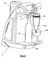
図9は、釈放可能締結部材102を固定係合部材101のガイド70に配置した後におけるサーブ装置4の作動状態を示す。押しボタン91を押すことにより、ウィンは細長チューブ26をから流出し、グラス100に注ぎ込まれる。
FIG. 9 shows the operating state of the serve device 4 after the
より正確には、図6につき説明したように、押しボタン91を押し込むことにより供給されるガスは、ダクト56に達して可動素子53を下方に押しこむ。次に、ガスは環状チャネル81から、薄膜38の上面に達し、薄膜38を変形させる。このようにして、薄膜は継手部材60のフランジ61の上面に対して所定圧力で合致し、緊密な連結を確実にする。ストッパ39はその開放時間を、薄膜38を変形させることができるようにするため、所定の遅延をもってストッパの開口部開放を確実にする圧力に較正する。ストッパ39が開くとき、ガスはボトル内に流入するが、孔33(図7参照)を設けたバルブ本体34における逆止バルブ32を開放し、孔33を経て流れる。バルブ32を通過後、ガスはチャンバ83を通過して、流入ダクト24からボトルに入る。
More precisely, as described with reference to FIG. 6, the gas supplied by pushing the
この後即座に、ワインがボトルの内側底部領域から首端部25′まで上昇し、つぎに送給ダクト25および最終的にバルブ27を経て細長チューブ26から流出する。
Immediately after this, the wine rises from the inner bottom region of the bottle to the neck end 25 ′ and then flows out of the
本発明のある実施形態においては、図11に示すように、細長チューブ26の代わりに混合器110を設け、ワインはこの混合器を通過して適度に酸化される。
In one embodiment of the invention, as shown in FIG. 11, a
図10は、ねじ山112により連結取り付け具111上に装着する中空体113により構成した空/液混合器110の断面図を示す。
FIG. 10 shows a cross-sectional view of the air /
好適な実施形態において、ねじ山112は、以下のもの、すなわち、
‐強制連結のための円形ねじ山、または
‐導入ねじのための螺旋ねじ山
よりなるグループから選択する。
In a preferred embodiment, the
Select from the group consisting of a circular thread for forced connection or a helical thread for the lead-in screw.
特に、連結取り付け具111はバルブ27を装着する入口区域116を備える。さらにまた、大気圧の外気が混合器110内に入り込む開孔119を有する。混合器110とバルブ27との間の緊密連結は、Oリング28の存在により確実になる。
In particular, the
特に、本体113はバルブ27を通過した後即座にワインが流入するチャンバ117を有し、次に狭い横断面部分115を経て、円錐送給ダクト118に向かって流れる。狭い横断面部分115はチャネル114を介して外部に連通する。
In particular, the
ワインの酸化は、ベンチュリー作用による空気吸引によって遂行される。実際、既知のように、狭い横断面部分115を通過するときにワインはその速度を増し、圧力低下を発生し、この結果、ワインと混合する空気をチャネル114から吸引する。連結取り付け具111における孔119は、チャンバ117内の圧力低下を回避して、大気圧に維持する。
Oxidation of wine is accomplished by air suction by the Venturi action. In fact, as is known, as it passes through the
したがって、図11に示すように混合器110を配置することにより、グラス110内に予め酸化したワインを注ぎ入れる。このことは、特に、古いワインのような風味を出すために酸化を必要とするときに有利である。
Therefore, by arranging the
特別な実施形態について上述した説明は、本発明を概念的視点から完全に明らかにするものであり、したがって、最近の知識を適用することで当業者はそのような実施形態に対して、さらなる研究を必要とせず本発明から逸脱することなく変更および/または様々な応用をすることができ、そのような応用および変更は上述の特別な実施形態と等価であるとみなすことができることを理解されたい。本明細書に記載する、異なる機能を実施するための手段および材料は、この理由により本発明の範囲から逸脱することなく、異なる特性のものとすることができる。本明細書に使用した文言および用語は説明目的のためであり、限定する意図はないことを理解されたい。 The above description of particular embodiments fully clarifies the present invention from a conceptual point of view, and thus, by applying recent knowledge, one skilled in the art can further study such embodiments. It should be understood that modifications and / or various applications can be made without departing from the invention without departing from the invention, and that such applications and modifications can be considered equivalent to the particular embodiments described above. . The means and materials for performing the different functions described herein may be of different characteristics for this reason without departing from the scope of the invention. It should be understood that the language and terminology used herein is for the purpose of description and is not intended to be limiting.
Claims (18)
‐前記ボトルネックの口部に固定できる、通常閉じている常閉の釈放可能締結部材と、
‐前記釈放可能締結部材を収容するよう構成した固定係合部材と、
‐前記固定係合部材に関連して設けたガス送給バルブと、
‐前記ガス送給バルブと空気回路的に接続した加圧ガス供給装置と、
‐前記ガス送給バルブと前記釈放可能締結部材との間の緊密係合を提供する緊密係合手段と、を備え、
前記固定係合部材は、
‐前記釈放可能締結部材の存在を検知し、前記釈放可能締結部材の存在/不在に応じて、前記送給バルブの操作を、それぞれ許可/阻止するセンサを有し、
前記釈放可能締結部材は、
‐前記加圧ガスを受け入れて前記ボトル内に送るよう構成し、加圧ガス供給源に緊密接続する接続手段と、
‐ガスを送給する際に液体を注ぎ出すサーブ手段であって、前記ボトルの内側底部領域と液圧回路的に接続する、該サーブ手段と、
‐前記加圧ガス供給源から引き離したとき、前記ボトルを閉鎖状態に維持し、前記ボトル内の加圧ガスを維持するボトル閉止手段と、
を有し、
前記ボトル閉止手段は、
‐締結手段により前記ボトルの口部に固定することができる閉鎖部材であって、前記閉鎖部材を通過して前記ボトル内に導入する加圧ガスの流入ダクト、前記ボトルの内側底部領域から液体を送出して外部にサーブするための液体送給ダクト、および前記ボトルネックに緊密に係合可能な円筒形部分を有する閉鎖部材と、
‐流入ダクトに設けた、前記加圧ガスを供給するときに開き、またそれ以外全ての場合に閉じるよう構成した逆止バルブと、
‐前記液体送給ダクトに設けた逆止バルブと、を有する
ことを特徴とする装置。 A serving device for serving a liquid that may be affected by oxygen from an already opened bottle, in particular wine, without oxygen by blowing a pressurized gas into the bottle, the bottle being a bottleneck at the mouth In the serve device,
- it can be fixed to the mouth portion of the bottle neck, and normally closed releasable fastening member is normally closed,
A fixed engagement member configured to receive the releasable fastening member;
-A gas feed valve provided in connection with the fixed engagement member;
-A pressurized gas supply device connected in air circuit with the gas delivery valve;
-Tight engagement means for providing a close engagement between the gas delivery valve and the releasable fastening member;
The fixed engagement member is
-A sensor for detecting the presence of the releasable fastening member and allowing / blocking the operation of the feeding valve according to the presence / absence of the releaseable fastening member,
The releaseable fastening member is:
-A connecting means adapted to receive said pressurized gas and deliver it into said bottle, and to be intimately connected to a source of pressurized gas;
A serve means for pouring liquid when delivering gas, said serve means being connected in a hydraulic circuit with the inner bottom region of said bottle;
- when pulled away from the source of pressurized gas to maintain the bottle in the closed state, and the bottle closure means for maintaining the pressurized gas in the bottle,
Have
The bottle closing means is
-A closing member that can be fixed to the mouth of the bottle by a fastening means, wherein an inflow duct for a pressurized gas that passes through the closing member and is introduced into the bottle, the liquid from the inner bottom region of the bottle A liquid delivery duct for delivering and serving to the outside, and a closure member having a cylindrical portion that can be tightly engaged with the bottleneck;
-A check valve provided in the inflow duct that is configured to open when supplying the pressurized gas and to close in all other cases;
-A check valve provided in the liquid supply duct;
A device characterized by that .
前記釈放可能締結部材に向かってガスが流れるようになる前に前記薄膜の変形を可能にするよう設けた較正可能なストッパと、
を有する構成とした、装置。 The apparatus according to claim 1, before Ki緊 Mitsugakarigo means, said the surface of the tightly engaging means comprising a thin film configured to closely match the shape is changed by the pressure of the feed gas A thin film that securely performs the close engagement,
A calibratable stopper provided to allow deformation of the membrane before gas flows toward the releasable fastening member;
A device having a configuration.
‐ガスシリンダ、
‐ガス供給ネットワーク
よりなるグループから選択した、装置。 The apparatus according to claim 1 , wherein the pressurized gas supply device includes:
-Gas cylinders,
A device selected from the group consisting of a gas supply network.
‐窒素、
‐アルゴン
よりなるグループから選択した、装置。 2. The apparatus according to claim 1 , wherein the pressurized gas is an inert gas and / or a noble gas that does not contain oxygen so as not to oxidize the wine,
-nitrogen,
An apparatus selected from the group consisting of argon.
‐液体を自由に送出させる細いチューブ、
‐開閉バルブを有して液体を送出させる細いチューブ、
‐空気/液体混合器
からなるグループから選択した、装置。 The apparatus according to claim 1, before Symbol Saab means is connected to the liquid delivery duct and hydraulically,
-A thin tube that allows liquid to flow freely,
-A thin tube with an open / close valve to deliver liquid,
An apparatus selected from the group consisting of an air / liquid mixer.
‐バヨネット連結、
‐ねじ連結、
‐スナップ連結、
‐スライド連結、
‐磁気連結、
からなるグループから選択した連結により、前記結合面を、前記固定係合部材に係合可能な構成とした、装置。 15. The device according to claim 14 , wherein the following connection:
-Bayonet consolidation,
-Screw connection,
-Snap connection,
-Slide connection,
-Magnetic coupling,
An apparatus in which the coupling surface is engageable with the fixed engagement member by connection selected from the group consisting of:
‐押しボタンタップ、
‐ハンドルタップ、
‐ワインをサーブするために前記ボトルを開き、また前記ボトル内に空気が逆流することを防ぐ逆止バルブ、
‐ソレノイドバルブ、
からなるグループから選択した、装置。 2. The apparatus according to claim 1 , wherein the serving means is connected to the liquid supply duct in a hydraulic circuit, and the liquid supply duct includes an opening / closing valve,
-Push button tap,
-Handle tap,
- Open the bottle to serve wine, also prevents air from flowing back into the bottle check valve,
-Solenoid valve,
A device selected from the group consisting of:
Applications Claiming Priority (1)
| Application Number | Priority Date | Filing Date | Title |
|---|---|---|---|
| PCT/EP2007/010328 WO2009068054A2 (en) | 2007-11-28 | 2007-11-28 | Apparatus for serving by-the-glass wine from a bottle, or other liquid that can be affected by oxygen |
Publications (2)
| Publication Number | Publication Date |
|---|---|
| JP2011504855A JP2011504855A (en) | 2011-02-17 |
| JP5315357B2 true JP5315357B2 (en) | 2013-10-16 |
Family
ID=39869971
Family Applications (1)
| Application Number | Title | Priority Date | Filing Date |
|---|---|---|---|
| JP2010535221A Expired - Fee Related JP5315357B2 (en) | 2007-11-28 | 2007-11-28 | A device that serves a glass of wine or other liquid that may be affected by oxygen from a bottle. |
Country Status (10)
| Country | Link |
|---|---|
| US (1) | US20100276453A1 (en) |
| EP (1) | EP2231504B1 (en) |
| JP (1) | JP5315357B2 (en) |
| CN (1) | CN101888965A (en) |
| AU (1) | AU2007361754B2 (en) |
| BR (1) | BRPI0722184A2 (en) |
| CA (1) | CA2706981A1 (en) |
| ES (1) | ES2409181T3 (en) |
| MX (1) | MX2010005848A (en) |
| WO (1) | WO2009068054A2 (en) |
Families Citing this family (25)
| Publication number | Priority date | Publication date | Assignee | Title |
|---|---|---|---|---|
| CN101717061B (en) * | 2009-09-29 | 2012-09-05 | 浙江心连心电器有限公司 | Refrigeration machine for refreshing red wine and automatically pouring wine |
| ITAR20100001A1 (en) * | 2010-01-11 | 2011-07-12 | Gianni Innocenti | DISTRIBUTION AND CONTROL DEVICE FOR THE DISTRIBUTION OF BEVERAGES PARTICULARLY OF MOSS, SPARKLING WINE, CHAMPAGNE AND SIMILAR WINES |
| ITAP20100001A1 (en) * | 2010-02-23 | 2011-08-24 | Giovanni Vagnoni | AUTONOMOUS DEVICE WITH REDUCED DIMENSIONS TO BE APPLIED TO STANDARD CONTAINERS FOR PUNCHING AND STORAGE OF WINE OR OTHER LIQUIDS BY MEANS OF PROTECTIVE GAS ENTRY |
| IT1400676B1 (en) * | 2010-06-29 | 2013-06-28 | Enomatic Srl | TAP FOR DISPOSAL DEVICES FOR DRINKS FROM CONTAINERS SUCH AS BOTTLES AND THE LIKE. |
| CN101966975B (en) * | 2010-10-15 | 2012-08-08 | 胡丰 | Constant-pressure type pressure-reducing valve |
| CN102153040B (en) * | 2011-01-18 | 2015-06-03 | 龚央丹 | Wine refrigerating device |
| FR2997931B1 (en) * | 2012-11-12 | 2015-12-18 | Michael Paetzold | DEVICE FOR TASTING A BOTTLE WINE AND MACHINE FOR DISCHARGING AND REBOUCHER A BOTTLE EQUIPPED WITH SAID DEVICE |
| EP2938939B1 (en) * | 2012-12-31 | 2017-11-08 | Arçelik Anonim Sirketi | A cooling device comprising an adaptor |
| ITRM20130133A1 (en) * | 2013-03-06 | 2013-06-05 | Fabrizio Tummino | BEVERAGE CLOSING AND STORAGE DEVICE SUCH AS WINE SPARKLING CHAMPAGNE AND SIMILAR LIQUORS BOTTLED WITH A PRESSURE OR SCREW CAP |
| CN103712407B (en) * | 2013-12-11 | 2016-05-18 | 清华大学 | A kind of refrigerator of can be used for breaking a seal refreshing red wine automatic wine-pouring |
| RS54809B1 (en) * | 2014-07-30 | 2016-10-31 | Miloš Milošević | Device for dispensing and distributing the beverage from bottle |
| FR3044000B1 (en) * | 2015-11-24 | 2017-12-15 | Gregoire Henry | DEVICE AND METHOD FOR SAMPLING A LIQUID |
| CN111960371A (en) * | 2015-11-25 | 2020-11-20 | 科拉温股份有限公司 | Beverage extractor with controller |
| FR3053262A1 (en) | 2016-07-04 | 2018-01-05 | Adrien Plecis | SYSTEM FOR PREPARING A PERSONALIZED COMPOSITION BY PRESSURE |
| TWI632473B (en) * | 2016-12-21 | 2018-08-11 | 王健亞 | Information feed method for physical objects |
| IT201600132480A1 (en) * | 2016-12-29 | 2018-06-29 | Winefit S R L | DEVICE FOR THE CONSERVATION AND DISTRIBUTION OF WINE, OR OTHER ALTERABLE LIQUID FROM OXYGEN, FROM A BOTTLE FOR CONSUMPTION TO THE GLASS |
| JP6508847B2 (en) * | 2017-06-19 | 2019-05-08 | 株式會社塩山製作所 | Wine server |
| CN107655670B (en) * | 2017-09-28 | 2024-02-27 | 上海阀门厂股份有限公司 | Safety valve testing device and safety valve testing method |
| AU2018399625B2 (en) | 2018-01-05 | 2023-12-07 | Coravin, Inc. | Beverage dispenser and container stopper |
| KR20210019407A (en) * | 2018-06-15 | 2021-02-22 | 산토리 홀딩스 가부시키가이샤 | Beverage server, beverage server system and beverage delivery method |
| EP3810544B1 (en) * | 2018-06-25 | 2022-05-04 | Coravin, Inc. | Apparatus for pressurising a beverage container, including a container stopper |
| BE1026635B1 (en) * | 2018-09-20 | 2020-04-21 | Anheuser Busch Inbev Sa | Kit for dispensing a beverage through a dispensing tube that includes a dispensing valve |
| EP3883881A1 (en) * | 2018-11-21 | 2021-09-29 | Coravin, Inc. | Replaceable beverage outlet and conduit for dispenser |
| CN110585980A (en) * | 2019-09-25 | 2019-12-20 | 中信戴卡股份有限公司 | Mixing device |
| WO2023146435A1 (en) * | 2022-01-31 | 2023-08-03 | Георгий Шотаевич ХУРОШВИЛИ | Software and hardware system for remotely dispensing portions of wine |
Family Cites Families (22)
| Publication number | Priority date | Publication date | Assignee | Title |
|---|---|---|---|---|
| US3156252A (en) * | 1961-12-08 | 1964-11-10 | Mack S Johnston | Beer siphon assembly |
| US3208639A (en) * | 1964-05-06 | 1965-09-28 | Finesse Products Inc | Sealed fluid dispensing system for oxidizable fluids |
| US3428218A (en) * | 1966-05-12 | 1969-02-18 | Felix V Coja | Liquid dispenser |
| US3883043A (en) * | 1973-10-18 | 1975-05-13 | Charles Robert Lane | Dispensor for vintage wines |
| US4392578A (en) * | 1980-09-25 | 1983-07-12 | Fipp Beverly A | Stopper apparatus for content contamination prevention |
| US4473174A (en) * | 1982-07-30 | 1984-09-25 | Howard John Cream | Wine preserver and dispenser |
| US4499931A (en) * | 1982-11-15 | 1985-02-19 | Crown Cork & Seal Company, Inc. | Nitrogen injector system |
| US4595121A (en) * | 1984-09-10 | 1986-06-17 | Sheldon Schultz | Apparatus and method for dispensing and preserving bottled degradable liquids such as wine and the like |
| US4702396A (en) * | 1986-02-10 | 1987-10-27 | Gwiazda Ronald E | Apparatus for preserving and dispensing wine |
| US4706847A (en) * | 1986-05-05 | 1987-11-17 | Senmar Corporation | Dispenser for wine |
| FR2616767B1 (en) * | 1987-06-22 | 1990-02-16 | Cruover Sa | DEVICE FOR PROVIDING BOTTLED LIQUID BEVERAGE, ESPECIALLY WINE |
| US5139179A (en) * | 1990-10-09 | 1992-08-18 | Cecil Kenneth B | Apparatus for dispensing and preserving liquids |
| US5499758A (en) * | 1994-08-19 | 1996-03-19 | Mccann's Engineering & Manufacturing Co. | Liquid dispenser for use with containers |
| JP3044201U (en) * | 1997-05-02 | 1997-12-16 | 日本炭酸瓦斯株式会社 | Sake dispenser |
| DE69840304D1 (en) * | 1997-09-04 | 2009-01-15 | Heineken Tech Services | Soda Fountain |
| PT1204555E (en) * | 1999-08-16 | 2004-11-30 | Cash & Carry Angehrn Ag | PROCESS FOR THE CONSERVATION OF AN OPEN BEVERAGE BOTTLE |
| US6607100B2 (en) * | 2001-11-26 | 2003-08-19 | Vin Valet, Inc. | Wine or champagne preservation and dispensing apparatus |
| KR100598278B1 (en) * | 2002-05-23 | 2006-07-07 | 요시다 에이지 | Device, unit, and system for fluid extraction |
| GB0220531D0 (en) * | 2002-09-04 | 2002-10-09 | Bermar Internat Ltd | Method amd apparatus for preserving the contents of beverage containers |
| JP4264939B2 (en) * | 2003-09-05 | 2009-05-20 | モトマン株式会社 | Thermal insulation device equipped with a bottled liquid quality holding device |
| JP2006176148A (en) * | 2004-12-22 | 2006-07-06 | Mikuni Sogyo Kk | Bottled beverage server device |
| US20070181602A1 (en) * | 2006-02-07 | 2007-08-09 | Napa Technology, Llc | Method and apparatus for liquid dispensing head and system |
-
2007
- 2007-11-28 WO PCT/EP2007/010328 patent/WO2009068054A2/en active Application Filing
- 2007-11-28 CN CN2007801017099A patent/CN101888965A/en active Pending
- 2007-11-28 BR BRPI0722184-3A patent/BRPI0722184A2/en not_active IP Right Cessation
- 2007-11-28 JP JP2010535221A patent/JP5315357B2/en not_active Expired - Fee Related
- 2007-11-28 CA CA2706981A patent/CA2706981A1/en not_active Abandoned
- 2007-11-28 MX MX2010005848A patent/MX2010005848A/en active IP Right Grant
- 2007-11-28 EP EP07856293A patent/EP2231504B1/en not_active Not-in-force
- 2007-11-28 ES ES07856293T patent/ES2409181T3/en active Active
- 2007-11-28 AU AU2007361754A patent/AU2007361754B2/en not_active Expired - Fee Related
- 2007-11-28 US US12/742,838 patent/US20100276453A1/en not_active Abandoned
Also Published As
| Publication number | Publication date |
|---|---|
| US20100276453A1 (en) | 2010-11-04 |
| WO2009068054A2 (en) | 2009-06-04 |
| CN101888965A (en) | 2010-11-17 |
| MX2010005848A (en) | 2010-12-20 |
| EP2231504A2 (en) | 2010-09-29 |
| AU2007361754B2 (en) | 2014-03-27 |
| CA2706981A1 (en) | 2009-06-04 |
| BRPI0722184A2 (en) | 2014-08-05 |
| WO2009068054A3 (en) | 2009-11-12 |
| ES2409181T3 (en) | 2013-06-25 |
| EP2231504B1 (en) | 2013-02-27 |
| AU2007361754A1 (en) | 2009-06-04 |
| JP2011504855A (en) | 2011-02-17 |
Similar Documents
| Publication | Publication Date | Title |
|---|---|---|
| JP5315357B2 (en) | A device that serves a glass of wine or other liquid that may be affected by oxygen from a bottle. | |
| US11753290B2 (en) | Roving beverage dispensing unit | |
| US5139179A (en) | Apparatus for dispensing and preserving liquids | |
| EP0448598B1 (en) | Device for selectively dispensing and mixing a plurality of beverages | |
| CN112723292B (en) | compact beverage dispensing unit | |
| US20110036451A1 (en) | Device for dosed dispensing of a liquid from a composite container and method for filling the composite container ("liquid dispensing flair") | |
| UA110496C2 (en) | DISPENSING APPLIANCE PROVIDED WITH REMOVABLE DISPENSING CARTRIDGE <http://patents.justia.com/patent/20130214011> | |
| CN104903230B (en) | Beverage distribution component and the container in beverage distribution component | |
| US20080023501A1 (en) | Tap Unit for a Beverage Dispenser | |
| US11591203B2 (en) | Wine dispenser | |
| EP1352873A1 (en) | Beverage dispenser | |
| MX2014013193A (en) | Beverage dispensing unit with openable pinch valve. | |
| CN106103336B (en) | Integrated bucket connector | |
| US20060032870A1 (en) | Beer keg tap | |
| JP2002337991A (en) | Beverage discharging device | |
| US20040124216A1 (en) | Self-contained octopus adaptor tap | |
| US583205A (en) | Siphon-pump | |
| WO2005046541A3 (en) | Assembly for packaging and dispensing a liquid, comprising membrane microfilters | |
| US170982A (en) | Improvement in vents | |
| US757886A (en) | Liquid-dispensing apparatus. | |
| JP2013018491A (en) | Elbow and liquid ejecting device |
Legal Events
| Date | Code | Title | Description |
|---|---|---|---|
| A621 | Written request for application examination |
Free format text: JAPANESE INTERMEDIATE CODE: A621 Effective date: 20101111 |
|
| A977 | Report on retrieval |
Free format text: JAPANESE INTERMEDIATE CODE: A971007 Effective date: 20120727 |
|
| A131 | Notification of reasons for refusal |
Free format text: JAPANESE INTERMEDIATE CODE: A131 Effective date: 20120731 |
|
| A601 | Written request for extension of time |
Free format text: JAPANESE INTERMEDIATE CODE: A601 Effective date: 20121030 |
|
| A602 | Written permission of extension of time |
Free format text: JAPANESE INTERMEDIATE CODE: A602 Effective date: 20121106 |
|
| A521 | Request for written amendment filed |
Free format text: JAPANESE INTERMEDIATE CODE: A523 Effective date: 20121130 |
|
| TRDD | Decision of grant or rejection written | ||
| A01 | Written decision to grant a patent or to grant a registration (utility model) |
Free format text: JAPANESE INTERMEDIATE CODE: A01 Effective date: 20130618 |
|
| A61 | First payment of annual fees (during grant procedure) |
Free format text: JAPANESE INTERMEDIATE CODE: A61 Effective date: 20130708 |
|
| R150 | Certificate of patent or registration of utility model |
Free format text: JAPANESE INTERMEDIATE CODE: R150 |
|
| LAPS | Cancellation because of no payment of annual fees |