JP5312306B2 - Medium fixing device and image forming apparatus - Google Patents
Medium fixing device and image forming apparatus Download PDFInfo
- Publication number
- JP5312306B2 JP5312306B2 JP2009281881A JP2009281881A JP5312306B2 JP 5312306 B2 JP5312306 B2 JP 5312306B2 JP 2009281881 A JP2009281881 A JP 2009281881A JP 2009281881 A JP2009281881 A JP 2009281881A JP 5312306 B2 JP5312306 B2 JP 5312306B2
- Authority
- JP
- Japan
- Prior art keywords
- medium
- recording medium
- holding
- fixing device
- roller
- Prior art date
- Legal status (The legal status is an assumption and is not a legal conclusion. Google has not performed a legal analysis and makes no representation as to the accuracy of the status listed.)
- Expired - Fee Related
Links
Images


Abstract
Description
本発明は、媒体固定装置及び画像形成装置に係り、特に、インクジェット記録装置などの画像記録装置において、記録媒体を固定保持して搬送する媒体固定装置及び画像形成装置に関する。 The present invention relates to a medium fixing apparatus and an image forming apparatus, and more particularly, to a medium fixing apparatus and an image forming apparatus for fixing and transporting a recording medium in an image recording apparatus such as an ink jet recording apparatus.
従来より、画像形成装置として、多数のノズル(インク吐出口)を配列させたインクジェットヘッドを有し、このインクジェットヘッドに対して記録媒体を相対的に搬送し、ノズルから記録媒体に向けてインクをインク液滴として吐出することにより、記録媒体上に画像を形成するインクジェットプリンタ(インクジェット記録装置)が知られている。 2. Description of the Related Art Conventionally, an image forming apparatus has an inkjet head in which a large number of nozzles (ink discharge ports) are arranged, and a recording medium is conveyed relative to the inkjet head, and ink is directed from the nozzle toward the recording medium. An ink jet printer (ink jet recording apparatus) that forms an image on a recording medium by ejecting it as ink droplets is known.
このとき、記録媒体を保持固定してインクジェットヘッドを有する印字部へ搬送する搬送手段として、ドラム形状やベルト形状などの形態があり、また、記録媒体を保持固定する方法としては、エア吸着(真空吸着)方式や静電吸着方式が知られている。 At this time, the conveyance means for holding and fixing the recording medium and conveying it to the printing unit having the inkjet head includes forms such as a drum shape and a belt shape. As a method for holding and fixing the recording medium, air adsorption (vacuum) Adsorption) method and electrostatic adsorption method are known.
例えば、ドラム端面側にドラム内の各負圧生成室と外部とを連通する複数の吸込口と各吸込口を開閉可能なシャッター、及び各シャッターをドラムの回転方向の下流側から上流側に向けて順次に開閉可能な開閉機構を設け、吸込ファンを回転させた状態で各シャッターをドラム回転方向の並び順とは逆に順次開放することにより、印字媒体の先端部を負圧吸着保持し、印字媒体の先端側より後方側部分も対向する吸込孔を介して順次にドラム外周面に負圧吸着保持するようにしたインクジェットプリンタの媒体保持装置が知られている(例えば、特許文献1等参照)。 For example, on the drum end surface side, a plurality of suction ports communicating with each negative pressure generating chamber in the drum and the outside, a shutter capable of opening and closing each suction port, and each shutter is directed from the downstream side to the upstream side in the drum rotation direction Opening and closing mechanism that can be opened and closed sequentially, with the suction fan rotated, each shutter is opened sequentially in reverse of the order of rotation in the drum rotation direction, thereby holding the front end of the print medium with negative pressure adsorption and holding, 2. Description of the Related Art A medium holding device for an ink jet printer is known in which a negative pressure adsorption and holding is sequentially performed on a drum outer peripheral surface through a suction hole that also faces a rear side portion from the front end side of a print medium (see, for example, Patent Document 1). ).
また、例えば、媒体と接触する開口部を有する流路形成部と圧力発生部との間に吸着圧力を絞る機能を有する流路制御部を設けることで、小さい吸着領域から強い吸着圧力で媒体を吸着保持するとともに、吸着圧力を維持し、媒体の吸着圧力不足による位置ズレを防止することで、様々なサイズの記録媒体への対応を可能とした媒体保持装置が知られている(例えば、特許文献2等参照)。 In addition, for example, by providing a flow path control unit having a function of reducing the adsorption pressure between the flow path forming unit having an opening that contacts the medium and the pressure generation unit, the medium can be moved from a small adsorption region with a strong adsorption pressure. There is known a medium holding device that can cope with recording media of various sizes by holding the suction and maintaining the suction pressure and preventing a positional shift due to insufficient suction pressure of the medium (for example, patents). Reference 2 etc.).
また、例えば、インク記録領域にあって、記録媒体のインク記録面に対して裏面側に設けられ、インク記録領域における記録媒体を相対的に強く静電吸着する第1領域と相対的に弱く静電吸着する第2領域を交互に複数分散して有する静電吸着手段を備えたインクジェット記録装置が知られている(例えば、特許文献3等参照)。 Further, for example, in the ink recording area, provided on the back surface side with respect to the ink recording surface of the recording medium, the recording medium in the ink recording area is relatively weak and static compared to the first area that electrostatically attracts the recording medium relatively strongly. There is known an ink jet recording apparatus provided with electrostatic adsorption means having a plurality of second areas to be electroadsorbed alternately dispersed (see, for example, Patent Document 3).
しかしながら、インクジェット記録方法において、水性インクを用いる場合、セルロースの水素結合の切断、乾燥による水素結合の再結合により、印刷用紙が変形してしまい、これにより、裏面印刷の吸着時に吸着皺が発生し、通紙性の悪化や、描画ムラを引き起こすという問題がある。 However, when water-based ink is used in the ink jet recording method, the printing paper is deformed due to the breakage of hydrogen bonds in cellulose and the recombination of hydrogen bonds due to drying. There is a problem that the paper passing property is deteriorated and drawing unevenness is caused.
このとき、例えば上記特許文献1に記載のものでは、記録媒体をドラム上で吸着してローラで先端から後端に向けてしごくことによって皺を伸ばすようにしている。確かに、このような方法は表面印刷の紙や、3次元変形が大きくない印刷物への裏面印刷時には有効である。しかし、3次元変形が大きく、紙に皺が発生しやすい画像においては、特許文献1に記載されたような一方に皺を寄せる方式は好ましくないことが本発明者らによって確認された。 At this time, for example, in the one described in Patent Document 1, the wrinkles are stretched by attracting the recording medium on the drum and squeezing it from the front end to the rear end with a roller. Certainly, such a method is effective at the time of printing on the back side of a surface-printed paper or a printed matter that does not have a large three-dimensional deformation. However, the present inventors have confirmed that a method of bringing a wrinkle to one side as described in Patent Document 1 is not preferable for an image that is large in three-dimensional deformation and easily wrinkles on paper.
また、上記特許文献2に記載のものは、ドラム上に記録媒体を吸着して搬送するものであって、様々なサイズの記録媒体に対応するようにしたものであり、記録媒体の3次元変形に対する観点は存在しない。 In addition, the one described in Patent Document 2 is for attracting and transporting a recording medium on a drum and is adapted to the recording medium of various sizes. There is no point of view.
また、上記特許文献3に記載のものは、記録媒体を静電吸着でベルト搬送するもので、相対的に強く静電吸着する第1領域と相対的に弱く静電吸着する第2領域を交互に複数分散することにより皺を一方に寄せずに分散させるようにしてはいるが、やはり紙変形が厳しい画像においては搬送中に用紙浮きが発生してしまうという問題がある。 Further, the one described in Patent Document 3 conveys a recording medium by electrostatic attraction, and alternates between a first area that is relatively strongly electrostatically attracted and a second area that is relatively weakly electrostatically attracted. However, there is a problem that the paper floats during conveyance in an image with severe paper deformation.
本発明は、このような事情に鑑みてなされたもので、3次元変形した記録媒体に記録する場合であっても、記録媒体を吸着搬送する際、記録媒体に皺が寄らないようにすることのできる媒体固定装置及び画像形成装置を提供することを目的とする。 The present invention has been made in view of such circumstances, and even when recording on a three-dimensionally deformed recording medium, the recording medium is prevented from wrinkling when sucked and conveyed. An object of the present invention is to provide a medium fixing device and an image forming apparatus capable of performing the above.
前記目的を達成するために、請求項1に記載の発明は、シート状の媒体を吸着する吸着穴に連通する複数の吸着溝を有する媒体保持面に前記媒体を吸着する媒体吸着手段と、前記媒体保持面に吸着される前記媒体の保持及び解放が可能な媒体保持手段と、前記媒体を前記媒体保持面に吸着した状態で、前記媒体を所定の方向に搬送する媒体固定搬送手段と、前記複数の吸着溝に連通し、各吸着溝に吸着圧力を発生させる吸着圧力発生手段と、前記媒体をその搬送方向に沿って、前記媒体の中央部から先端部及び後端部に向けてしごく媒体しごき手段と、を備え、前記媒体を前記媒体保持手段で保持し前記媒体保持面に吸着して、前記媒体を搬送中に、一時的に前記媒体保持手段による前記媒体の保持を解放して、前記媒体しごき手段により、前記媒体をその中央部から先端部及び後端部に向けてしごいた後、再び前記媒体保持手段により前記媒体を保持することを特徴とする媒体固定装置を提供する。 In order to achieve the object, the invention described in claim 1 includes a medium adsorbing means for adsorbing the medium on a medium holding surface having a plurality of adsorbing grooves communicating with an adsorbing hole for adsorbing a sheet-like medium, and Medium holding means capable of holding and releasing the medium adsorbed on the medium holding surface, medium fixed conveying means for conveying the medium in a predetermined direction with the medium adsorbed on the medium holding surface, and An adsorption pressure generating means that communicates with the plurality of adsorption grooves and generates an adsorption pressure in each adsorption groove, and a medium that moves the medium from the central portion toward the front end portion and the rear end portion along the conveying direction of the medium. An ironing means, holding the medium by the medium holding means and adsorbing the medium to the medium holding surface, and temporarily releasing the holding of the medium by the medium holding means while transporting the medium; By the medium ironing means, After squeezed toward the serial medium at the tip portion and the rear end portion from the center portion, to provide a medium fixing device, characterized in that for holding the medium again by the medium holding means.
これにより、3次元変形した記録媒体に記録する場合であっても、記録媒体を吸着搬送する際、記録媒体に皺が寄らないようにすることが可能となる。 Accordingly, even when recording is performed on a three-dimensionally deformed recording medium, it is possible to prevent the recording medium from wrinkling when the recording medium is sucked and conveyed.
また、請求項2に示すように、前記媒体保持手段は、前記媒体の搬送方向の長さ少なくとも1/4以上が吸着され搬送されてから、前記媒体の保持を一時解放することを特徴とする。 According to a second aspect of the present invention, the medium holding unit temporarily releases the holding of the medium after at least 1/4 of the length in the conveyance direction of the medium is adsorbed and conveyed. .
これにより、記録媒体が離れてしまうことなく、記録媒体を確実に吸着することができる。 As a result, the recording medium can be reliably adsorbed without leaving the recording medium.
また、請求項3に示すように、前記媒体しごき手段は、前記媒体をその搬送方向に沿って、前記媒体を前記媒体固定搬送手段に押し付けて前記媒体の中央部から先端部に向けてしごく第1の部材と、前記媒体を前記媒体固定搬送手段に押し付けて前記媒体を中央部から後端部に向けてしごく第2の部材の2つの部材からなることを特徴とする。 According to a third aspect of the present invention, the medium squeezing unit is configured to squeeze the medium from the central portion toward the tip end portion by pressing the medium against the medium fixing and conveying unit along the conveying direction of the medium. 1 member, and the said medium is pressed against the said medium fixed conveyance means, It consists of two members, the 2nd member which squeezes the said medium toward a rear-end part from the center part.
また、請求項4に示すように、前記第1の部材は、前記媒体の搬送とともに前記媒体の中央部から先端部に向かって移動することにより前記媒体をしごき、前記第2の部材は固定されていて、前記媒体が搬送されることにより前記媒体をその中央部から後端部に向かってしごくことを特徴とする。 According to a fourth aspect of the present invention, the first member squeezes the medium by moving from the central portion of the medium toward the leading end portion with the conveyance of the medium, and the second member is fixed. In addition, the medium is squeezed from a central portion toward a rear end portion by the conveyance of the medium.
これにより、記録媒体を中央部から各端部に向けて双方向にしごくことで皺を分散させることができる。 Thereby, wrinkles can be dispersed by bi-directionally squeezing the recording medium from the center toward each end.
また、請求項5に示すように、前記第1の部材は、前記媒体をしごき始める前は前記第2の部材と隣接した位置に配置され、前記媒体の搬送にともない、前記媒体の先端部が前記第1の部材の下を通過後、前記媒体がその長さの1/4以上が通過し、かつその長さの1/2までは通過していないときに、しごきを開始し、前記媒体の先端部に向けて移動し、前記媒体の先端部までしごくことを特徴とする。 According to a fifth aspect of the present invention, the first member is disposed at a position adjacent to the second member before starting to iron the medium. After passing under the first member, when the medium passes more than 1/4 of its length and does not pass up to 1/2 of its length, ironing is started, and the medium It moves toward the front-end | tip part of this, It is characterized by squeezing to the front-end | tip part of the said medium.
これにより、なるべく広い範囲を双方にしごくことが可能となる。 As a result, it is possible to squeeze a wide range as much as possible.
また、請求項6に示すように、前記第1の部材及び前記第2の部材は、前記媒体をしごき始める前は前記媒体とは接触しないように浮き上がった位置に待機しており、しごきを開始するときに前記媒体と接触することを特徴とする。 According to a sixth aspect of the present invention, the first member and the second member are waiting at a position where they are lifted up so as not to come into contact with the medium before starting to iron the medium, and start ironing. And the medium is in contact with the medium.
これにより、媒体を逆方向にしごいて却って皺を発生させてしまうことを防止することができる。 As a result, it is possible to prevent the medium from being squeezed in the opposite direction and generating wrinkles.
また、請求項7に示すように、前記第1の部材は、前記媒体の搬送速度よりも速く前記媒体の中央部から先端部に向かって移動することを特徴とする。 According to a seventh aspect of the present invention, the first member moves from the central portion of the medium toward the tip portion faster than the conveyance speed of the medium.
これにより、第1の部材は確実に記録媒体を中央部から先端部に向けてしごくことが可能となる。 As a result, the first member can reliably squeeze the recording medium from the central portion toward the tip portion.
また、請求項8に示すように、前記第1の部材は、前記媒体を先端部までしごいた後、次に搬送されて来る媒体のしごきを開始する位置に戻る際、前記媒体とは接触しないように浮き上がって戻ることを特徴とする。 In addition, as shown in claim 8, the first member contacts the medium when the medium is squeezed to the tip and then returned to a position where the next transported medium starts to be squeezed. It is characterized by lifting up and returning so as not to.
これにより、第1の部材が戻るときにすでにしごいた記録媒体を逆にしごいてしまい皺を発生させてしまうことを防ぐことができる。 As a result, it is possible to prevent the recording medium that has already been squeezed from being reversed when the first member returns to cause wrinkles.
また、請求項9に示すように、前記媒体しごき手段はローラであることを特徴とする。 According to a ninth aspect of the present invention, the medium ironing means is a roller.
また、請求項10に示すように、前記媒体しごき手段はブレードであることを特徴とする。 According to a tenth aspect of the present invention, the medium ironing means is a blade.
また、請求項11に示すように、前記第1の部材及び第2の部材は、どちらか一方がローラで他方がブレードであることを特徴とする。 Further, according to an eleventh aspect, one of the first member and the second member is a roller and the other is a blade.
また、請求項12に示すように、前記媒体吸着手段は、前記媒体の中央部と四隅における吸着力が、それ以外の部分の吸着力よりも強いことを特徴とする。 Further, according to a twelfth aspect of the present invention, the medium adsorbing means is characterized in that the adsorbing force at the central portion and the four corners of the medium is stronger than the adsorbing force at other portions.
これにより、記録媒体の浮きや皺の発生を防止することができる。 Thereby, it is possible to prevent the recording medium from floating and wrinkles.
また、請求項13に示すように、前記媒体吸着手段は、前記吸着溝が形成される中間シートと、前記吸着穴が形成される吸着シートを重ねた構造を有することを特徴とする。 According to a thirteenth aspect of the present invention, the medium suction unit has a structure in which an intermediate sheet in which the suction grooves are formed and a suction sheet in which the suction holes are formed are stacked.
また、請求項14に示すように、吸着シートは、中央部と四隅においては吸着穴が密に配置され、それ以外の部分では吸着穴が疎に配置されていることを特徴とする。 According to a fourteenth aspect of the present invention, the suction sheet is characterized in that suction holes are densely arranged at the central portion and the four corners, and suction holes are sparsely arranged at other portions.
これにより、前記媒体の中央部と四隅における吸着力が、それ以外の部分の吸着力よりも強くなるようにできる。 As a result, the suction forces at the center and the four corners of the medium can be made stronger than the suction forces at the other portions.
また、同様に前記目的を達成するために、請求項15に記載の発明は、請求項1〜13のいずれかに記載の媒体固定装置と、前記媒体固定装置によって固定され搬送される前記媒体に対して画像を記録する記録ヘッドと、を備えたことを特徴とする画像形成装置を提供する。 Similarly, in order to achieve the above object, the invention described in claim 15 includes the medium fixing device according to any one of claims 1 to 13 and the medium fixed and conveyed by the medium fixing device. An image forming apparatus comprising: a recording head for recording an image.
これにより、皺の無い、高品質の画像を形成することが可能となる。 Thereby, it is possible to form a high-quality image free from wrinkles.
以上説明したように、本発明によれば、3次元変形した記録媒体に記録する場合であっても、記録媒体を吸着搬送する際、記録媒体に皺が寄らないようにすることが可能となる。 As described above, according to the present invention, even when recording on a three-dimensionally deformed recording medium, it is possible to prevent the recording medium from wrinkling when the recording medium is sucked and conveyed. .
以下、添付図面を参照して、本発明に係る媒体固定装置及び画像形成装置について詳細に説明する。 Hereinafter, a medium fixing device and an image forming apparatus according to the present invention will be described in detail with reference to the accompanying drawings.
図1は、本発明に係る媒体固定装置が適用された画像形成装置としてのインクジェット記録装置の一実施形態を示す概略構成図である。 FIG. 1 is a schematic configuration diagram showing an embodiment of an ink jet recording apparatus as an image forming apparatus to which a medium fixing device according to the present invention is applied.
このインクジェット記録装置100は、描画部116の圧胴(描画ドラム170)に保持された記録媒体124(以下、単に「用紙」ともいう)にインクジェットヘッド172M、172K、172C、172Yから複数色のインクを打滴して所望のカラー画像を形成する圧胴直描方式のインクジェット記録装置であり、インクの打滴前に記録媒体124上に処理液(ここでは凝集処理液)を付与し、処理液とインク液を反応させて記録媒体124上に画像形成を行う2液反応(凝集)方式が適用されたオンデマンドタイプの画像形成装置である。
The ink
すなわち、図1に示すように、インクジェット記録装置100は、主として、給紙部112、処理液付与部114、描画部116、乾燥部118、定着部120、及び排紙部122を備えて構成されている。
That is, as shown in FIG. 1, the
給紙部112は、記録媒体124を処理液付与部114に供給する機構であり、当該給紙部112には、枚葉紙である記録媒体124が積層されている。給紙部112には、給紙トレイ150が設けられ、この給紙トレイ150から記録媒体124が一枚ずつ処理液付与部114に給紙されるようになっている。
The
本例のインクジェット記録装置100では、記録媒体124として、紙種や大きさ(用紙サイズ)の異なる複数種類の記録媒体124を使用することができる。給紙部112において各種の記録媒体をそれぞれ区別して集積する複数の用紙トレイ(図示省略)を備え、これら複数の用紙トレイの中から給紙トレイ150に送る用紙を自動で切り換える態様も可能であるし、必要に応じてオペレータが用紙トレイを選択し、若しくは交換する態様も可能である。なお、本例では、記録媒体124として、枚葉紙(カット紙)を用いるが、連続用紙(ロール紙)から必要なサイズに切断して給紙する構成も可能である。
In the
処理液付与部114は、記録媒体124の記録面に処理液を付与する機構である。処理液は、描画部116で付与されるインク中の色材(本例では顔料)を凝集させる色材凝集剤を含んでおり、この処理液とインクとが接触することによって、インクは色材と溶媒との分離が促進される。
The processing
図1に示すように、処理液付与部114は、給紙胴152、処理液ドラム154、及び処理液塗布装置156を備えている。処理液ドラム154は、記録媒体124を保持し、回転搬送させるドラムである。処理液ドラム154は、その外周面に爪形状の保持手段(グリッパー)155を備え、この保持手段155の爪と処理液ドラム154の周面の間に記録媒体124を挟み込むことによって記録媒体124の先端を保持できるようになっている。処理液ドラム154は、その外周面に吸引孔を設けるとともに、吸引孔から吸引を行う吸引手段を接続してもよい。これにより記録媒体124を処理液ドラム154の周面に密着保持することができる。
As shown in FIG. 1, the treatment
処理液ドラム154の外側には、その周面に対向して処理液塗布装置156が設けられる。処理液塗布装置156は、処理液が貯留された処理液容器と、この処理液容器の処理液に一部が浸漬されたアニックスローラと、アニックスローラと処理液ドラム154上の記録媒体124に圧接されて計量後の処理液を記録媒体124に転移するゴムローラとで構成される。この処理液塗布装置156によれば、処理液を計量しながら記録媒体124に塗布することができる。
A processing
本実施形態では、ローラによる塗布方式を適用した構成を例示したが、これに限定されず、例えば、スプレー方式、インクジェット方式などの各種方式を適用することも可能である。 In the present embodiment, the configuration in which the application method using the roller is exemplified, but the present invention is not limited to this. For example, various methods such as a spray method and an ink jet method can be applied.
処理液付与部114で処理液が付与された記録媒体124は、処理液ドラム154から中間搬送部126を介して描画部116の描画ドラム170へ受け渡される。
The
描画部116は、描画ドラム170、用紙抑えローラ174、及びインクジェットヘッド172M、172K、172C、172Yを備えている。なお、図1では図示を省略しているが、用紙抑えローラ174は、2つのローラから構成され、上側(描画ドラム170の回転方向下流側)のローラのみが用紙搬送方向に沿って動き、下側のローラは固定されている。この用紙抑えローラ174を含む媒体固定装置の詳細については後述する。
The
描画ドラム170は、処理液ドラム154と同様に、その外周面に記録媒体の先端部を保持固定する爪形状の保持手段(グリッパー)171を備えている。描画ドラム170に固定された記録媒体124は、記録面が外側を向くようにして搬送され、この記録面にインクジェットヘッド172M、172K、172C、172Yからインクが付与される。
Similar to the
インクジェットヘッド172M、172K、172C、172Yは、それぞれ記録媒体124における画像形成領域の最大幅に対応する長さを有するフルライン型のインクジェット方式の記録ヘッド(インクジェットヘッド)であり、そのインク吐出面には、画像形成領域の全幅にわたってインク吐出用のノズルが複数配列されたノズル列が形成されている。各インクジェットヘッド172M、172K、172C、172Yは、記録媒体124の搬送方向(描画ドラム170の回転方向)と直交する方向に延在するように設置されている。
The inkjet heads 172M, 172K, 172C, and 172Y are full-line inkjet recording heads (inkjet heads) each having a length corresponding to the maximum width of the image forming area on the
描画ドラム170上に密着保持された記録媒体124の記録面に向かって各インクジェットヘッド172M、172K、172C、172Yから、対応する色インクの液滴が吐出されることにより、処理液付与部114で予め記録面に付与された処理液にインクが接触し、インク中に分散する色材(顔料)が凝集され、色材凝集体が形成される。これにより、記録媒体124上での色材流れなどが防止され、記録媒体124の記録面に画像が形成されるようになっている。
The droplets of the corresponding color ink are ejected from the inkjet heads 172M, 172K, 172C, and 172Y toward the recording surface of the
なお、本例では、CMYKの標準色(4色)の構成を例示したが、インク色や色数の組み合わせについては本実施形態には限定されず、必要に応じて淡インク、濃インク、特別色インクを追加してもよい。例えば、ライトシアン、ライトマゼンタなどのライト系インクを吐出するインクジェットヘッドを追加する構成も可能であり、各色ヘッドの配置順序も特に限定されない。 In this example, the configuration of CMYK standard colors (four colors) is illustrated, but the combination of ink colors and the number of colors is not limited to this embodiment, and light ink, dark ink, and special ink are used as necessary. Color ink may be added. For example, it is possible to add an ink jet head that discharges light ink such as light cyan and light magenta, and the arrangement order of the color heads is not particularly limited.
以上のように構成された描画部116により、記録媒体124に対してシングルパスで描画を行うことができる。
The
描画部116で画像が形成された記録媒体124は、描画ドラム170から中間搬送部128を介して乾燥部118の乾燥ドラム176へ受け渡される。
The
乾燥部118は、色材凝集作用により分離された溶媒に含まれる水分を乾燥させる機構であり、図1に示すように、乾燥ドラム176、及び溶媒乾燥装置178を備えている。
The drying
乾燥ドラム176は、処理液ドラム154と同様に、その外周面に爪形状の保持手段(グリッパー)177を備え、この保持手段177によって記録媒体124の先端を保持できるようになっている。
Similar to the
溶媒乾燥装置178は、乾燥ドラム176の外周面に対向する位置に配置され、複数のハロゲンヒータ180と、各ハロゲンヒータ180の間にそれぞれ配置された温風噴出しノズル182とで構成される。
The
各温風噴出しノズル182から記録媒体124に向けて吹き付けられる温風の温度と風量、各ハロゲンヒータ180の温度を適宜調節することにより、様々な乾燥条件を実現することができる。
Various drying conditions can be realized by appropriately adjusting the temperature and air volume of the hot air blown toward the
また、乾燥ドラム176の表面温度は50℃以上に設定されている。記録媒体124の裏面から加熱を行うことによって乾燥が促進され、定着時における画像破壊を防止することができる。なお、乾燥ドラム176の表面温度の上限については、特に限定されるものではないが、乾燥ドラム176の表面に付着したインクをクリーニングするなどのメンテナンス作業の安全性(高温による火傷防止)の観点から75℃以下(より好ましくは60℃以下)に設定されることが好ましい。
The surface temperature of the drying drum 176 is set to 50 ° C. or higher. Drying is accelerated by heating from the back surface of the
乾燥ドラム176の外周面に、記録媒体124の記録面が外側を向くように(すなわち、記録媒体124の記録面が凸側となるように湾曲させた状態で)保持し、回転搬送しながら乾燥することで、記録媒体124の皺や浮きの発生を防止でき、これらに起因する乾燥ムラを確実に防止することができる。
It is held on the outer peripheral surface of the drying drum 176 so that the recording surface of the
乾燥部118で乾燥処理が行われた記録媒体124は、乾燥ドラム176から中間搬送部130を介して定着部120の定着ドラム184に受け渡される。
The
定着部120は、定着ドラム184、ハロゲンヒータ186、定着ローラ188、及びインラインセンサ190で構成される。定着ドラム184は、処理液ドラム154と同様に、その外周面に爪形状の保持手段(グリッパー)185を備え、この保持手段185によって記録媒体124の先端を保持できるようになっている。
The fixing
定着ドラム184の回転により、記録媒体124は記録面が外側を向くようにして搬送され、この記録面に対して、ハロゲンヒータ186による予備加熱と、定着ローラ188による定着処理と、インラインセンサ190による検査が行われる。
With the rotation of the fixing
ハロゲンヒータ186は、所定の温度(例えば、180℃)に制御される。これにより、記録媒体124の予備加熱が行われる。
The
定着ローラ188は、乾燥させたインクを加熱加圧することによってインク中の自己分散性ポリマー微粒子を溶着し、インクを被膜化させるためのローラ部材であり、記録媒体124を加熱加圧するように構成される。具体的には、定着ローラ188は、定着ドラム184に対して圧接するように配置されており、定着ドラム184との間でニップローラを構成するようになっている。これにより、記録媒体124は、定着ローラ188と定着ドラム184との間に挟まれ、所定のニップ圧(例えば、0.15MPa)でニップされ、定着処理が行われる。
The fixing
また、定着ローラ188は、熱伝導性の良いアルミなどの金属パイプ内にハロゲンランプを組み込んだ加熱ローラによって構成され、所定の温度(例えば、60〜80℃)に制御される。この加熱ローラで記録媒体124を加熱することによって、インクに含まれるラテックスのTg温度(ガラス転移点温度)以上の熱エネルギーが付与され、ラテックス粒子が溶融される。これにより、記録媒体124の凹凸に押し込み定着が行われるとともに、画像表面の凹凸がレベリングされ、光沢性が得られる。
The fixing
なお、図1の実施形態では、定着ローラ188を1つだけ設けた構成となっているが、画像層厚みやラテックス粒子のTg特性に応じて、複数段設けた構成でもよい。
In the embodiment of FIG. 1, only one fixing
一方、インラインセンサ190は、記録媒体124に定着された画像について、チェックパターンや水分量、表面温度、光沢度などを計測するための計測手段であり、CCDラインセンサなどが適用される。
On the other hand, the in-
上記の如く構成された定着部120によれば、乾燥部118で形成された薄層の画像層内のラテックス粒子が定着ローラ188によって加熱加圧されて溶融されるので、記録媒体124に固定定着させることができる。また、定着ドラム184の表面温度は50℃以上に設定されている。定着ドラム184の外周面に保持された記録媒体124を裏面から加熱することによって乾燥が促進され、定着時における画像破壊を防止することができるとともに、画像温度の昇温効果によって画像強度を高めることができる。
According to the fixing
なお、熱可塑性樹脂粒子を含んだインクに代えて、UV硬化性樹脂などの活性光線硬化性樹脂を含んだインクを用いる場合には、加熱定着の定着ローラ188に代えて、UVランプや紫外線LD(レーザダイオード)アレイなど、活性光線を照射する手段が設けられる。
When an ink containing an actinic ray curable resin such as a UV curable resin is used instead of the ink containing the thermoplastic resin particles, a UV lamp or an ultraviolet LD is used instead of the fixing
定着部120に続いて排紙部122が設けられている。排紙部122には、排紙ユニット192が設置される。定着部120の定着ドラム184から排紙ユニット192までの間に、渡し胴194、搬送チェーン196が設けられている。搬送チェーン196は、張架ローラ198に巻き掛けられている。定着ドラム184を通過した記録媒体124は、渡し胴194を介して、搬送チェーン196に送られ、搬送チェーン196から紙ユニット192へと受け渡される。
Subsequent to the fixing
また、図1には示されていないが、本例のインクジェット記録装置100は、上記構成の他、各インクジェットヘッド172M、172K、172C、172Yにインクを供給するインク貯蔵/装填部、処理液付与部114に対して処理液を供給する手段を備えるとともに、各インクジェットヘッド172M、172K、172C、172Yのクリーニング(ノズル面のワイピング、パージ、ノズル吸引等)を行うヘッドメンテナンス部や、用紙搬送路上における記録媒体124の位置を検出する位置検出センサ、装置各部の温度を検出する温度センサなどを備えている。
Although not shown in FIG. 1, the ink
次に、図1のインクジェット記録装置100に適用された媒体固定装置について説明する。
Next, a medium fixing device applied to the ink
図2に、本発明の実施形態に係る描画ドラム170を斜視図で示す。なお、ここでは描画ドラム170について、記録媒体124の保持固定機能を説明するが、これについては他の搬送ドラムも同様の構成である。
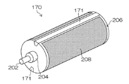
FIG. 2 is a perspective view of the
図2に示すように、描画ドラム170は、円筒形状を有し、回転軸202が長手方向の両端部において軸受204で支持され、回転軸202を回転させることで、ドラム外周面206に保持されて記録媒体(ここでは図示省略)が所定の方向に搬送されるようになっている。
As shown in FIG. 2, the drawing
また前述したように、描画ドラム170の外周面206には記録媒体の先端部を保持固定する爪形状の保持手段171が複数設けられている。図2では、描画ドラム170の回転軸202を挟んで対称となる位置に2つの保持手段171が設けられている。なお、設けられる保持手段171の個数は、このように2つに限定されるものではなく、外周面を3等分する位置に3つの保持手段を備えるようにしてもよい。
As described above, the outer
なお、詳しい図示は省略するが、保持手段171は、描画ドラム170の外周面206にドラム長手方向に沿って形成された凹部内に記録媒体124の先端部を挟み込んで挟持する複数のグリッパーを有して構成されている。
Although not shown in detail, the holding
描画ドラム170の外周面206のう、図にハッチングで示した、記録媒体124を吸着保持する記録媒体保持領域208には、吸着穴が所定の配置パターンで複数設けられている。吸着穴は、描画ドラム170内部の吸着管路と連通し、この吸着管路は描画ドラム170内部の真空管路(ともに図示省略)と連通し、さらにこの真空管路は描画ドラム170の側面部に設けられる図示を省略した連結部等を介して真空ポンプ及びコンプレッサーと接続されている。
A plurality of suction holes are provided in a predetermined arrangement pattern in a recording
記録媒体124を記録媒体保持領域208に保持した状態で真空ポンプを動作させ、描画ドラム170内の真空管路、吸着管路を介して外周面206の記録媒体保持領域208の吸着穴に真空(負圧)を発生させることで、記録媒体保持領域208に記録媒体124を真空吸着することができる。
The vacuum pump is operated in a state where the
一方、真空ポンプとコンプレッサーの接続を切り換えて、記録媒体保持領域208に記録媒体124を置かない状態で、コンプレッサーを動作させて圧縮空気を供給すると、上述した描画ドラム170の真空管路、吸着管路を介して外周面206の吸着穴から圧縮空気(エア)が排出され、吸着管路内及び吸着穴の内部に進入したインクミストや紙粉などをエアとともに排出することができる。
On the other hand, when the connection between the vacuum pump and the compressor is switched and the compressed air is supplied by operating the compressor without placing the
また、図3は、描画ドラム170の吸着保持機能を説明するための分解斜視図である。
FIG. 3 is an exploded perspective view for explaining the suction holding function of the
図3に示すように、描画ドラム170は、ドラム本体部210、中間シート212、吸着シート214を含んでいる。なお、図3では、保持手段171によって2分された外周面の片側だけについて中間シート212及び吸着シート214を表示したが、もちろん他方の側についても同様である。
As shown in FIG. 3, the drawing
吸着シート214には、多数の吸着穴216が形成されている。また、中間シート212には、各吸着穴216と連通する複数の吸着溝218が所定の配列パターンに従って設けられている。さらに、各吸着溝218の軸方向中央部には他の部分よりも幅の狭い絞り部220が設けられており、ドラム本体部210には、この絞り部220と連通するドラム吸着溝222が設けられている。
A large number of suction holes 216 are formed in the
ドラム吸着溝222は、図3に示すように、ドラム本体部210の半周分に対して2本ドラム吸着溝222A,222Bを備える態様でもよいし、3本以上のドラム吸着溝でドラム本体部210の半周分をカバーしてもよい。なお、必要な吸着圧力や真空ポンプの容量によってはドラム本体部210の半周分を1本のドラム吸着溝222でカバーすることも可能である。しかし、ドラム本体部210の半周分を1本のドラム吸着溝222でカバーすると、ドラム吸着溝222に接続される中間シート212の吸着溝218の数が多くなってしまい、効率が悪くなるので、少なくとも2本のドラム吸着溝222A、222Bによってドラム本体部210の半周分をカバーする構造が好ましい。
As shown in FIG. 3, the
また、ドラム吸着溝222Aの一方の端部にはドラム吸着穴224が設けられ、ドラム吸着溝222Aは、ドラム吸着穴224を介してドラム本体部210の内部に設けられた真空流路(図示省略)と連通されている。なお、ドラム吸着溝222Bについても同様である。
Also, a
描画ドラム170は、ドラム本体部210のドラム吸着溝222と中間シート212の絞り部220の位置合わせがされ、ドラム本体部210の外周面206に中間シート212を巻きつけて密着させて固定するとともに、吸着シート214に設けられる吸着穴216が中間シート212のいずれかの吸着溝218と連通するように、中間シート212の吸着溝218と吸着シート214の吸着穴216の位置合わせがされ、中間シート212の上に吸着シート314を巻きつけて密着させて固定した構造を有している。
The drawing
吸着シート214に設けられる吸着穴216の配置パターンは、中間シート212の吸着溝218のパターンに対応していることが好ましい。このとき、吸着穴216のうち、吸着溝218と連通しないものがあってもよい。
The arrangement pattern of the suction holes 216 provided in the
次に、本実施形態において、最も好ましい吸着シート214の吸着穴216の配置パターンについて説明する。
Next, in the present embodiment, the most preferable arrangement pattern of the suction holes 216 of the
図4に、本実施形態において最も好ましい吸着穴216の配置パターンを有する吸着シート214のイメージ図を示す。図4に示すものはあくまでイメージであり、実際の吸着シートそのもの(吸着穴の形や個数等)を表すものではない。
FIG. 4 shows an image diagram of the
吸着シート214には、多数の吸着穴216が所定の配置パターンに従って設けられている。すなわち、図4に示すように、本実施形態においては、吸着シート214の中央部と四隅において吸着穴216が密に配置され、その他の部分は吸着穴216が疎に配置されている。
The
このように、吸着シート214の吸着穴216の配置を中央部及び四隅を密にし、それ以外の部分を疎にするような配置パターンとしたことにより、記録媒体124に対する吸着力を、媒体中央部と媒体四隅の方がその他の部分よりも強くすることができる。
As described above, the suction holes 216 of the
吸着穴216の配置を、基本的に中央部を密にして外へ行くほど疎になるようにしたのは、皺が紙の端部の方へ逃げやすくするためである。また、四隅も吸着穴216の配置を密にしたのは、記録媒体124の先端部や後端部が浮きやすいので(いわゆる、頭浮き、尻浮き)、先端部や後端部で記録媒体124が浮くのを防止するためである。
The reason why the arrangement of the suction holes 216 is basically made narrower as the center portion is made denser is to make it easier to escape toward the edge of the paper. In addition, the reason why the suction holes 216 are densely arranged at the four corners is that the front end and the rear end of the
図4において、吸着シート214の縦方向は、略描画ドラム170のドラム本体部210の半周分の長さであり、吸着シート214の横方向は、略描画ドラム170のドラム本体部210の軸方向の長さである。また、実際の吸着シート214の描画ドラム170の周方向の両端は、ドラム本体部210に固定するための折り返し構造を有している。
In FIG. 4, the vertical direction of the
また吸着シート214は実際には、中間シート212の絞り部220(図3参照)に対応する部分を非開口部として吸着穴を設けないことで、絞り部220の圧力損失を制限する(圧力損失を絞る)機能を確保するようにすることが好ましい。
In addition, the
吸着シート214は、吸着圧力によって凹まない厚みが必要であり、かつ、ドラム本体部210に巻きつけてドラム本体部210(中間シート212)に密着させるためには薄いことが好ましい。吸着シートの厚みは、使用する材料の剛性及び柔軟性を考慮して、適宜厚みを決めるとよい。
The adsorbing
図では吸着穴216は円形として表されているが、記録媒体124をドラム本体部210に固定した状態では、吸着圧力による記録媒体124の変形量は周方向よりも軸方向のほうが大きくなるので、吸着穴216は、周方向を長軸方向、軸方向を短軸方向とした楕円形状又は長穴形状とすることで、記録媒体124の周方向の変形と軸方向の変形が均等になり、好ましい。また、吸着シート214の開口率を高めるために、開口形状(吸着穴の形状)を六角形などの多角形形状にする態様も好ましい。
In the drawing, the
次に、吸着シート214及び中間シート212の固定方法について説明する。
Next, a method for fixing the
先ず、中間シート212の上に吸着シート214を重ねてドラム本体部210に巻きつける。吸着シート214及び中間シート212に位置合わせ用のマーク、形状を設けておくことで、容易に、かつ、正確に2枚のシートの位置を合わせることが可能となる。
First, the
次に、吸着シート214の一方の折り曲げ構造及び中間シート212の折り曲げ構造をドラム本体部210の挟持構造(図示省略)に挿入し、固定する。吸着シート214の折り曲げ構造と、中間シート212の折り曲げ構造に切り欠きを設けておき、挟持構造に該切り欠きと嵌合する凸部を設けておくことで、吸着シート214の一方の折り曲げ構造及び中間シート212の折り曲げ構造をドラム本体部210の挟持構造に挿入したときの、吸着シート214、中間シート212及びドラム本体部210の位置合わせを容易、かつ、正確に行うことができる。
Next, one folding structure of the
吸着シート214の他方の折り曲げ構造をドラム本体部210の引張機構(図示省略)に取り付けるとともに、この引張機構によって周方向に沿ってテンションをかける。中間シート212の折り曲げ構造が設けられていない側の端部は、吸着シート214とドラム本体部210の間にはさんで密着させる。
The other bent structure of the
このようにして、ドラム本体部210の外周面206の曲面に沿って、吸着シート214及び中間シート212を密着させた状態で固定することができる。
In this way, the adsorbing
本例では、2枚のシート(吸着シート214及び中間シート212)を組み合わせて、真空流路の一部を形成する態様を例示したが、吸着シート214及び中間シート212を共通化した1枚のシートに吸着穴216、吸着溝218及び絞り部220を形成してもよい。例えば、1枚のシートの一方の面に吸着穴216の加工を行い、他方の面に吸着溝218及び絞り部220の加工を行うことで、吸着シート214及び中間シート212を1枚のシートで実現することも可能である。
In this example, the mode in which two sheets (the
以上のように構成された描画ドラム170により、記録媒体124を描画部116に保持搬送し、インクジェットヘッド172M、172K、172C、172Yから複数色のインクを打滴して記録媒体124上に所望のカラー画像が形成される。
By the
すなわち、記録媒体124を描画ドラム170の外周面206に密着させた後に、上で説明した真空吸着によって、記録媒体124は描画ドラム170の外周面206(記録媒体保持領域208、図2参照)に吸着固定され、描画ドラム170の外周面206から浮き上がりのない状態で、インクジェットヘッド172M、172K、172C、172Yの直下の印字領域に送られる。そして、インクジェットヘッド172M、172K、172C、172Yのそれぞれから吐出されたカラーインクによって記録媒体124上に所望の画像が形成される。
That is, after the
次に、本実施形態における媒体固定装置の皺のばし機構について説明する。 Next, a description will be given of the punching mechanism of the medium fixing device according to the present embodiment.
図5に、描画ドラム170の周辺を拡大して示す。
FIG. 5 shows an enlarged view of the periphery of the
図5に示すように、描画ドラム170の両側には、それぞれ中間搬送部(中間搬送ドラム)126及び128が配置され、描画ドラム170の上部にはインクジェットヘッド172M、172K、172C、172Yが配置されている。描画ドラム170は、記録媒体124(ここでは図示を省略)の先端部を保持する保持手段(グリッパー)171を周上180度対称な位置に備えており、同様に中間搬送部(中間搬送ドラム)126及び128もそれぞれ保持手段127及び129を備えている。
As shown in FIG. 5, intermediate conveyance units (intermediate conveyance drums) 126 and 128 are arranged on both sides of the
また、描画ドラム170は、用紙抑えローラ174を有しており、用紙抑えローラ174は、第1のローラ174A及び第2のローラ174Bの2つのローラから構成されている。ここで、図で上側に配置された第1のローラ174Aは図に矢印で示したように描画ドラム170の周面に沿って移動可能であり、一方下側に配置された第2のローラ174Bは固定されている。
The drawing
前述したように、処理液付与部114(図1参照)で処理液が付与された記録媒体124は、処理液ドラム154から中間搬送部126を介して描画部116の描画ドラム170へ受け渡され、描画ドラム170の外周面に真空吸着によって保持固定された記録媒体124は、記録面が外側を向くようにして搬送され、この記録面にインクジェットヘッド172M、172K、172C、172Yからインクが付与されて、記録媒体124の記録面に画像が形成されるようになっている。
As described above, the
次に、本実施形態の媒体固定装置における皺のばしの動作を図6のフローチャートに沿って説明する。 Next, the operation of spreading the bag in the medium fixing device of the present embodiment will be described with reference to the flowchart of FIG.
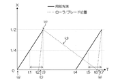
また、図7は、記録媒体124の先端の位置と描画ドラム170の周面に沿って移動する第1のローラ174Aの位置を示す線図である。図7は、第1のローラ174Aが停止している当初の位置(停止位置)から、記録媒体124の搬送方向下流側に記録媒体124の搬送方向の長さlの半分(l/2)の距離までの間において、記録媒体124の先端部と第1のローラが移動する様子を、縦軸に第1のローラ174Aの停止位置からの距離Xをとり、横軸に記録媒体124が第1のローラ174Aの停止位置に到達してからの時刻Tをとって、グラフで示したものである。
7 is a diagram showing the position of the leading end of the
また、図8は、図7中の符号(a)〜(e)で示した位置における記録媒体124と第1のローラ174A及び第2のローラ174Bの位置関係を平面状にして表示したものであり、各図の上方向が記録媒体124搬送方向である。
FIG. 8 is a plan view showing the positional relationship between the
以下、これらの図7及び図8を参照しつつ、図6のフローチャートに沿って説明する。 Hereinafter, description will be made along the flowchart of FIG. 6 with reference to FIGS. 7 and 8.
まず図6のステップS100において、中間搬送部126から描画ドラム170に記録媒体124が搬送されて来ると、描画ドラム170の爪形状の保持手段171(グリッパー)が記録媒体124の先端部を掴んで記録媒体124を保持する。そしてステップS110において、真空吸着により記録媒体124を描画ドラム170の外周面206(記録媒体保持領域208、図2参照)に吸着する。このとき、記録媒体124の中央部を強く、かつ端部に向けて弱く吸着する。なお、記録媒体124の四隅においても強く吸着して頭浮き及び尻浮きを防止することが好ましい。
First, in step S100 of FIG. 6, when the
そして記録媒体124を描画ドラム170の外周面206に保持固定して搬送する。記録媒体124が搬送されて、その先端部が第1のローラ174Aの停止位置にきた状態が図7の(a)の位置である。また、このときの状態を図8(a)に示す。このように第1のローラ174Aは移動前(しごき動作を開始する前)は第2のローラ174Bに隣接した位置に停止しているので、これは第2のローラ174Bの位置と略同一である。
Then, the
なお、しごき動作を開始する前においては、第1のローラ174A及び第2のローラ174Bはいずれも記録媒体124とは接触しないように描画ドラム170から離れて浮き上がった位置に待機している。そのため、記録媒体124が所定位置まで搬送されてしごき動作が開始されるまでは、記録媒体124は第1のローラ174A及び第2のローラ174Bには接触せずにこれらのローラの下を搬送される。これによって、記録媒体124の先端部が第1のローラ174A及び第2のローラ174Bの下を通過する際、先端部から搬送方向とは逆方向にしごかれて皺が寄ってしまうことが防止される。
Before starting the ironing operation, both the
そして、ステップS120において、記録媒体124の先端部が、第1のローラ174Aが停止している位置を記録媒体124の長さlの4分の1以上(l/4以上)通過したところで、図7に示す時刻t1において、保持手段171(グリッパー)による記録媒体124の保持を一時解放する。
Then, in step S120, when the leading end of the
その後、ステップS130において、記録媒体124の先端部が第1のローラ174Aの停止位置よりも記録媒体124の長さlの半分(l/2)だけ通過する前に、図7に示す時刻t2において、第1のローラ174Aは浮き上がった待機位置から下降し、記録媒体124に接触し、記録媒体124を描画ドラム170に押し付けながら、記録媒体124搬送方向に向けて移動を開始し、記録媒体124を先端部に向けてしごき始める。
Thereafter, in step S130, before the leading end of the
このときの状態が図7の(b)の位置であり、図8(b)に示す状態が対応する。図8(b)に示すように、第1のローラ174Aは、搬送される記録媒体124を、その搬送方向に追いかけるように移動して、記録媒体124を中央部から先端部に向けてしごいて行く。このとき、もちろん第1のローラ174Aが移動する速さは記録媒体124の搬送速度よりも速くなければならない。
The state at this time is the position shown in FIG. 7B, and the state shown in FIG. As shown in FIG. 8B, the
また、このとき、第1のローラ174Aと同時に第2のローラ174Bも浮き上がった待機位置から下降し、記録媒体124に接触し、記録媒体124を描画ドラム170に押し付けるが、第2のローラ174Bは固定されているので、記録媒体124が搬送されるのに伴い、記録媒体124は第2のローラ174Bによって、中央部から後端部に向けて自動的にしごかれて行く。
At this time, the
このとき、記録媒体124の先端部が第1のローラ174Aの停止位置を記録媒体124の長さlの半分(l/2)だけ通過し、記録媒体124の中央部が第1のローラ174Aの位置にきたときに、第1のローラ174Aがしごきを開始すると、第1のローラ174Aが記録媒体124の中央部から先端部まで丁度l/2だけしごくことができるので理想的である。しかし、実際にはスペースの関係から第1のローラ174Aがヘッドに当たってしまったり、第1のローラ174Aが非常な高速で移動しなければならない等の様々な問題が生じるため困難である。
At this time, the leading end portion of the
このように、記録媒体124をできるだけ長い範囲しごこうとすると、第1のローラ174Aがしごきを開始するタイミングはなるべく遅い方がよいが、あまり遅過ぎて記録媒体124の先端部が第1のローラ174Aの停止位置をl/2以上過ぎてからしごきを開始したのでは、第1のローラ174Aの移動速度にもよるが、先端部までしごききれない場合もある。
As described above, if the
そこで、現実的には、図7に示すように、記録媒体124の先端部が、第1のローラ174Aの停止位置から記録媒体124の長さのl/4乃至l/3程度の距離だけ進んだときに、第1のローラ174Aが動き始め、記録媒体124の先端部に向けてしごき、記録媒体124の先端部がインクジェットヘッドの手前に来るまでに、先端部までしごき終わるような速度で第1のローラ174Aが移動することが好ましい。これにより、第1のローラ174Aによるしごきの距離をできるだけ長くすることができる。
Therefore, in practice, as shown in FIG. 7, the leading end of the
なお、第1のローラ174Aが移動しながら記録媒体124をしごく際、第1のローラ174Aは回転しながら移動してもよいが、特に回転することなく単に移動するだけで記録媒体124を充分にしごくことができる。そこで、ローラの代わりにブレードを用いてもよい。このとき移動するローラ及び固定されるローラ両方ともブレードにしてもよいし、ローラとブレードを片方ずつ組み合わせて用いるようにしてもよい。
Note that when the
このようにして、図7に示す時刻t3(同時に符号(c)の位置)において第1のローラ174Aは記録媒体124の先端部に追いつき記録媒体124の前半部のしごきを完了する。このときの状態を図8(c)に示す。その後さらに記録媒体124を搬送すると、第2のローラ174Bによって、記録媒体124の中央部から後端部に向けて、記録媒体124の後半分がしごかれる。
In this manner, the
そして、記録媒体124の中央部から先端部まで第1のローラ174Aによるしごきが終了したら、ステップS140において、図7に示す時刻t3において再び保持手段171(グリッパー)により記録媒体124の先端部を掴み、記録媒体124を描画ドラム170の記録媒体保持領域208(図2参照)に保持固定する。
When the ironing by the
その後、描画ドラム170は、記録媒体124を保持固定してインクジェットヘッドの下まで搬送し、インクジェットヘッド172M、172K、172C、172Yからインクが付与されて、記録媒体124の記録面に画像が形成されるが、図7の記録媒体124先端部の位置を示すグラフは、該先端部が第1のローラ174Aの停止位置からl/2だけ進んだところから先は表示を省略している。
Thereafter, the drawing
第1のローラ174Aは、その後、最初の停止位置まで戻り、次に搬送されてくる記録媒体124’を上と同様にしてしごきを行う。
Thereafter, the
この次の記録媒体124’をしごくために、第1のローラ174Aが最初の位置(停止位置)に戻る動作を、図7及び図8により説明する。
The operation of returning the
図7に(c)の位置で示すように、第1のローラ174Aが記録媒体124の先端部までしごいたら、(d)の位置で示すように、第1のローラ174Aはもとの位置に引き返す。すなわち図8(d)に示すように、記録媒体124は続けていままでの搬送方向に搬送されて行くが、第1のローラ174Aは記録媒体124の搬送方向とは逆方向に移動して、固定された第2のローラ174Bに隣接する元の位置(停止位置)に戻って行く。また、次の記録媒体124’が搬送されてきている。
When the
このとき、第1のローラ174Aは、描画ドラム170に接触したまま戻り、記録媒体124の後端部へ向けて(後端部側は一度第2のローラ174Bによってしごかれているのであるが)再度しごいてもよいし、描画ドラム170には接触しないように浮き上がって戻るようにしてもよい。また、図8(d)に示すように、記録媒体124が第2のローラ174Bの下を通過した後は、第2のローラ174Bは浮き上がった待機位置に移動して次の記録媒体124’を待つ。
At this time, the
次の記録媒体124’も前の記録媒体124と同様に描画ドラム170の爪形状の保持手段171(グリッパー)によってその先端部を保持されて、真空吸着により描画ドラム170の外周面206(記録媒体保持領域208、図2参照)に吸着されて搬送される。
Similarly to the
そして、図7の時刻t4において、次の記録媒体124’が第2のローラ174Bの位置まで搬送され、時刻t5において、記録媒体124’の先端部が第2のローラ174Bの位置からl/4の距離まで搬送されると、前と同様に保持手段171(グリッパー)による記録媒体124’の保持が一時解放される。
Then, at time t4 in FIG. 7, the
そして前と同様に、記録媒体124’の先端部が第2のローラ174Bの位置からl/4以上l/2未満の距離だけ進んだ図7に示す所定の時刻t6において、第1のローラ174A及び第2のローラ174Bは浮き上がった位置から下降して次の記録媒体124’に接触し、7の(e)の位置で示すように、第1のローラ174Aによるしごきが開始される。なおこのとき、同時に第2のローラ174Bも記録媒体124’を略中央部から後端側へ向けてしごき始めている。
Then, as before, at the predetermined time t6 shown in FIG. 7 in which the leading end of the
このように時刻t6において次の記録媒体124’のしごき動作が開始されるので、この時刻t6までに第1のローラ174Aはもとの位置にもどらなければならない。第1のローラ174Aが図7に(c)で示す位置からもとの位置にもどる際、もどり始めは描画ドラム170と接触していてもよいが、第1のローラ174Aが次に搬送されて来る記録媒体124’の先端部と接触する位置以降においては描画ドラム170とは接触せずに浮き上がっていなければならない。少なくとも図7に示す時刻t4以降において浮き上がらせるようにすればよいが、戻る場合には完全に浮き上がって戻るように構成してもよい。
As described above, the ironing operation of the next recording medium 124 'is started at time t6, so that the
そして、図8(e)に示すように、もとの位置に戻った第1のローラ174Aは再び記録媒体124’の搬送方向に向かって描画ドラム170に接触しつつ移動を開始し、記録媒体124’の略中央部からその先端部に向かって記録媒体124’をしごいて行く。そして、記録媒体124’の先端部のしごき始めからの距離が略l/2となる時刻t7において第1のローラ174Aは先端部まで到達してしごきを終了する。しごき終了後、時刻t7において前と同様に保持手段171(グリッパー)が記録媒体124’の先端部を再度掴んで保持し、記録媒体124’はインクジェットヘッドの下へと搬送されて行く。
Then, as shown in FIG. 8E, the
このように図7に水平方向の矢印で示したように、保持手段171(グリッパー)が記録媒体124(記録媒体124’)を一時解放〜再度保持する時刻の範囲t1〜t3(t5〜t7)の任意の時点において第1のローラ174Aによるしごきを開始するようにすればよい。
Thus, as indicated by the horizontal arrows in FIG. 7, the time range t1 to t3 (t5 to t7) in which the holding means 171 (gripper) temporarily releases the recording medium 124 (recording medium 124 ′) and holds it again. The ironing by the
なお、第1のローラ174Aを、浮き上がらせることなく、描画ドラム170に接触させたまま戻す場合には、図9に示すように、次の記録媒体124’が第2のローラ174Bの位置に搬送される時刻t4までに第1のローラ174Aをもとの位置(停止位置)まで戻すようにすればよい。ただし、この場合でも、次の記録媒体124’の先端部が各ローラの下をしごきが開始される所定位置まで通過するまでは、これらの第1のローラ174A及び第2のローラ174Bは浮き上がった位置に待機していなければならない。
When the
次に、吸着シートの吸着穴の配置パターン、保持手段(グリッパー)による保持/解放、しごきの方向を様々に変えて実験を行った結果を次の表1に示す。 Next, Table 1 shows the results of experiments conducted by changing the arrangement pattern of the suction holes of the suction sheet, the holding / release by holding means (gripper), and the direction of ironing in various ways.

また、保持手段(グリッパー)が記録媒体の先端部を一度放してしごいた後再度掴むようにした場合には、しごき方が一方向(前→端)の場合には皺が発生し、判定は×である。 Also, if the holding means (gripper) releases the leading edge of the recording medium once and then grips it again, if the ironing method is in one direction (front → edge), wrinkles will occur and the judgment Is x.
そして、保持手段(グリッパー)が記録媒体の先端部を一度放してしごいた後再度掴むようにした場合にしごき方が双方向(中央→端)とした場合であっても、吸着シートが全面略均一に吸着穴が配置された通常の配置パターンの場合には、先頭部に皺が発生してしまい、判定としては△である。 And even if the holding means (gripper) releases the leading edge of the recording medium once and then grips it again, the suction sheet is completely covered even if the ironing is bidirectional (center → edge). In the case of the normal arrangement pattern in which the suction holes are arranged substantially uniformly, wrinkles are generated at the head, and the determination is Δ.
そして最も良いのは、保持手段(グリッパー)が記録媒体の先端部を一度放してしごいた後再度掴むようにした場合にしごき方が双方向(中央→端)とした場合であって、さらに吸着シートを本実施形態のように、吸着力を中央部を強く、周辺部ほど弱くした場合であり、この場合には皺の発生はみられず、判定は唯一○であった。 The best is when the holding means (gripper) releases the leading end of the recording medium once and then grips it again, and when the gripping means is bidirectional (center to end), In this case, as in the present embodiment, the suction force is increased in the central part and weaker in the peripheral part. In this case, no wrinkles are observed, and the determination is only ◯.
結果として、表1の8番の保持手段(グリッパー)が記録媒体の先端部を一度放してしごいた後再度掴むようにし、しごき方を双方向(中央→端)とし、さらに吸着シートを吸着力を中央部を強く周辺部ほど弱くした場合が良好で判定○であり、4番の保持手段(グリッパー)が記録媒体の先端部を一度放してしごいた後再度掴むようにし、しごき方を双方向(中央→端)とし、吸着シートを通常の配置パターンとした場合は、皺は発生するが許容範囲内で判定△であり、その他の場合はすべて皺が発生してしまい判定は×であった。 As a result, No. 8 holding means (gripper) in Table 1 releases the leading edge of the recording medium once and squeezes it again, making the squeezing direction bidirectional (center → end), and sucking the suction sheet The case where the force is stronger at the center and weaker at the periphery is good and the judgment is ○. The holding means (gripper) No. 4 releases the leading edge of the recording medium once and then grips it again. If it is bi-directional (center → end) and the suction sheet is in the normal arrangement pattern, wrinkles will occur, but the judgment will be within the allowable range. In all other cases, wrinkles will occur and the judgment will be x. there were.
以上説明したように、本実施形態においては、記録媒体を中央部から先端部、後端部それぞれに向かって双方向にしごくことで、皺を一方向に寄せないようにして、皺に対応したものである。そのため、例えば記録媒体の縦方向(搬送方向)の中央部を白抜きとし両端にベタ画像を記録したような画像の場合に、従来のように一方向に皺を寄せてしまうと記録媒体の後端部の中央に大きな浮きや皺が生じてしまっていたのに対して、同様の画像に対して本実施形態図6のフローチャートに示したような皺のばし方法を適用すると、皺が分散できることが確認された。 As described above, in this embodiment, the recording medium is bi-directionally moved from the central portion toward the front end portion and the rear end portion, so that the wrinkle is not moved in one direction, and the wrinkle is supported. Is. For this reason, for example, in the case of an image in which the central portion of the recording medium in the vertical direction (conveyance direction) is white and solid images are recorded at both ends, A large float or wrinkle has occurred in the center of the edge, but if the wrinkle spreading method as shown in the flowchart of FIG. 6 is applied to the same image, wrinkles can be dispersed. confirmed.
このように本実施形態は、上記特許文献1〜3に記載された発明が備えていない下記3つの特徴を有している。 As described above, the present embodiment has the following three features that the inventions described in Patent Documents 1 to 3 do not have.
(1)記録媒体中央部を強く、周辺部ほど弱く吸着する。そのため例えば吸着シートの吸着穴の配置パターンを中央部が密に、周辺部が疎となるようにする。ただし、四隅は記録媒体の浮き防止のため密とする。 (1) Adsorbs strongly at the center of the recording medium and weakly toward the periphery. Therefore, for example, the arrangement pattern of the suction holes of the suction sheet is set so that the central portion is dense and the peripheral portion is sparse. However, the four corners are close to prevent the recording medium from floating.
(2)記録媒体を吸着した後、一度記録媒体を掴んだ保持手段(グリッパー)を解放し、記録媒体をしごいた後、再度記録媒体を掴むようにする。 (2) After adsorbing the recording medium, the holding means (gripper) that once grips the recording medium is released, and after squeezing the recording medium, the recording medium is gripped again.
(3)記録媒体の先頭から尻に向けたしごきだけでなく、記録媒体の中央部からそれぞれ両端部に向けた双方向のしごきを行う。 (3) In addition to squeezing from the top of the recording medium toward the bottom, bidirectional squeezing is performed from the center of the recording medium to both ends.
これにより、例えば、両面印刷における裏面印刷時などのように、表面印刷で3次元変形した紙の裏面に印刷する場合に、記録媒体後端部中央に皺が寄るのを防ぎ、記録媒体外側に皺が逃げやすくすることができるとともに、記録媒体先端側においても浮きや皺を逃げやすくすることができる。 As a result, for example, when printing on the back side of paper that has been three-dimensionally deformed by front side printing, such as when printing on the back side in double-sided printing, it is possible to prevent wrinkles at the center of the rear end of the recording medium and It is possible to make it easier for the folds to escape and to make it easier for the floats and folds to escape even at the leading end side of the recording medium.
上で説明した例では、記録媒体を搬送ドラムに吸着するのに真空吸着方式を用いたが、吸着方法はこれに限定されるものではなく、例えば静電吸着方式でもよい。静電吸着の場合にも、記録媒体を吸着する際の吸着力が、記録媒体の中央部及び四隅の方がその他の部分よりも強くなるように構成されていることが好ましい。 In the example described above, the vacuum suction method is used to suck the recording medium onto the conveyance drum. However, the suction method is not limited to this, and for example, an electrostatic suction method may be used. Also in the case of electrostatic adsorption, it is preferable that the adsorption force when adsorbing the recording medium is configured so that the central portion and the four corners of the recording medium are stronger than the other portions.
以上、本発明の媒体固定装置及び画像形成装置について詳細に説明したが、本発明は、以上の例には限定されず、本発明の要旨を逸脱しない範囲において、各種の改良や変形を行ってもよいのはもちろんである。 Although the medium fixing device and the image forming apparatus of the present invention have been described in detail above, the present invention is not limited to the above examples, and various improvements and modifications are made without departing from the gist of the present invention. Of course it is also good.
100…インクジェット記録装置、112…給紙部、114…処理液付与部、116…描画部、118…乾燥部、120…定着部、122…排紙部、124…記録媒体、170…描画ドラム、171…保持手段(グリッパー)、172M、172K、172C、172Y…インクジェットヘッド、174…用紙抑えローラ、174A…第1のローラ、174B…第2のローラ、208…記録媒体保持領域、210…ドラム本体部、212…知友間シート、214…吸着シート、216…吸着穴、218…吸着溝、220…絞り部、222(222A、222B)…ドラム吸着溝
DESCRIPTION OF
Claims (15)
前記媒体保持面に吸着される前記媒体の保持及び解放が可能な媒体保持手段と、
前記媒体を前記媒体保持面に吸着した状態で、前記媒体を所定の方向に搬送する媒体固定搬送手段と、
前記複数の吸着溝に連通し、各吸着溝に吸着圧力を発生させる吸着圧力発生手段と、
前記媒体をその搬送方向に沿って、前記媒体の中央部から先端部及び後端部に向けてしごく媒体しごき手段と、
を備え、前記媒体を前記媒体保持手段で保持し前記媒体保持面に吸着して、前記媒体を搬送中に、一時的に前記媒体保持手段による前記媒体の保持を解放して、前記媒体しごき手段により、前記媒体をその中央部から先端部及び後端部に向けてしごいた後、再び前記媒体保持手段により前記媒体を保持することを特徴とする媒体固定装置。 Medium adsorbing means for adsorbing the medium to a medium holding surface having a plurality of adsorbing grooves communicating with an adsorbing hole for adsorbing a sheet-like medium;
Medium holding means capable of holding and releasing the medium adsorbed on the medium holding surface;
Medium fixing and conveying means for conveying the medium in a predetermined direction with the medium adsorbed to the medium holding surface;
An adsorption pressure generating means communicating with the plurality of adsorption grooves and generating an adsorption pressure in each of the adsorption grooves;
Medium squeezing means for squeezing the medium from the central part toward the front end part and the rear end part along the conveying direction;
And holding the medium by the medium holding means and adsorbing the medium to the medium holding surface, and temporarily releasing the holding of the medium by the medium holding means while transporting the medium, Thus, after the medium is squeezed from the central portion toward the front end portion and the rear end portion, the medium is held again by the medium holding means.
前記媒体固定装置によって固定され搬送される前記媒体に対して画像を記録する記録ヘッドと、
を備えたことを特徴とする画像形成装置。 The medium fixing device according to any one of claims 1 to 14,
A recording head for recording an image on the medium fixed and conveyed by the medium fixing device;
An image forming apparatus comprising:
Priority Applications (1)
| Application Number | Priority Date | Filing Date | Title |
|---|---|---|---|
| JP2009281881A JP5312306B2 (en) | 2009-12-11 | 2009-12-11 | Medium fixing device and image forming apparatus |
Applications Claiming Priority (1)
| Application Number | Priority Date | Filing Date | Title |
|---|---|---|---|
| JP2009281881A JP5312306B2 (en) | 2009-12-11 | 2009-12-11 | Medium fixing device and image forming apparatus |
Publications (3)
| Publication Number | Publication Date |
|---|---|
| JP2011121743A JP2011121743A (en) | 2011-06-23 |
| JP2011121743A5 JP2011121743A5 (en) | 2012-08-16 |
| JP5312306B2 true JP5312306B2 (en) | 2013-10-09 |
Family
ID=44286030
Family Applications (1)
| Application Number | Title | Priority Date | Filing Date |
|---|---|---|---|
| JP2009281881A Expired - Fee Related JP5312306B2 (en) | 2009-12-11 | 2009-12-11 | Medium fixing device and image forming apparatus |
Country Status (1)
| Country | Link |
|---|---|
| JP (1) | JP5312306B2 (en) |
Families Citing this family (4)
| Publication number | Priority date | Publication date | Assignee | Title |
|---|---|---|---|---|
| JP5400101B2 (en) * | 2011-07-27 | 2014-01-29 | 富士フイルム株式会社 | Medium conveying apparatus and image forming apparatus |
| JP5543988B2 (en) | 2012-02-21 | 2014-07-09 | 富士フイルム株式会社 | Paper transport apparatus and ink jet recording apparatus |
| JP5918159B2 (en) * | 2013-03-06 | 2016-05-18 | 富士フイルム株式会社 | Image forming apparatus |
| JP6703764B2 (en) * | 2016-06-20 | 2020-06-03 | 株式会社リコー | Sheet material suction device and image forming apparatus |
Family Cites Families (3)
| Publication number | Priority date | Publication date | Assignee | Title |
|---|---|---|---|---|
| JP3410313B2 (en) * | 1997-01-07 | 2003-05-26 | 東芝テック株式会社 | Medium holding device for inkjet printer |
| JPH10193719A (en) * | 1997-01-08 | 1998-07-28 | Tec Corp | Rotary holder for medium |
| JP5335282B2 (en) * | 2008-05-20 | 2013-11-06 | 富士フイルム株式会社 | Inkjet recording device |
-
2009
- 2009-12-11 JP JP2009281881A patent/JP5312306B2/en not_active Expired - Fee Related
Also Published As
| Publication number | Publication date |
|---|---|
| JP2011121743A (en) | 2011-06-23 |
Similar Documents
| Publication | Publication Date | Title |
|---|---|---|
| JP5235977B2 (en) | Image forming apparatus and image forming method | |
| JP5349202B2 (en) | Inkjet recording apparatus and inkjet recording method | |
| WO2015029822A1 (en) | Transfer body and imaging forming device including said transfer body | |
| JP2012166950A (en) | Conveying device, and image forming device | |
| JP2011020376A (en) | Printed matter seasoning apparatus and method, and inkjet recording apparatus | |
| JP5312306B2 (en) | Medium fixing device and image forming apparatus | |
| JP5422458B2 (en) | Medium conveying apparatus, image forming apparatus, and medium conveying method | |
| JP5224524B2 (en) | Inkjet recording device | |
| JP5400658B2 (en) | Inkjet recording apparatus and inkjet recording method | |
| JP2011136799A (en) | Recording medium conveyance method and apparatus, and image forming apparatus | |
| JP5147798B2 (en) | Inkjet recording apparatus and method | |
| JP5730487B2 (en) | Blower device and method | |
| WO2015060060A1 (en) | Inkjet recording device and medium transport method | |
| JP2010208107A (en) | Method for preventing curling, curling prevention device, and image forming apparatus | |
| WO2016047358A1 (en) | Nozzle wiping sheet, nozzle wiping unit, and image-forming device | |
| JP2010159127A (en) | Recorder | |
| JP2012179737A (en) | Image forming apparatus | |
| JP2012179724A (en) | Printing method and inkjet recording apparatus | |
| JP6092052B2 (en) | Inkjet recording device | |
| JP5363296B2 (en) | Image forming apparatus and image forming method | |
| JP2011020377A (en) | Ink-jet recording device and ink-jet recording method | |
| JP6114885B2 (en) | Wiping member, nozzle wiping unit, and image forming apparatus | |
| US8740373B2 (en) | Image forming method and image forming device | |
| JP2010173149A (en) | Image forming method and apparatus | |
| JP2016168780A (en) | Liquid supply device and image formation device |
Legal Events
| Date | Code | Title | Description |
|---|---|---|---|
| A621 | Written request for application examination |
Free format text: JAPANESE INTERMEDIATE CODE: A621 Effective date: 20120626 |
|
| A521 | Request for written amendment filed |
Free format text: JAPANESE INTERMEDIATE CODE: A523 Effective date: 20120704 |
|
| A977 | Report on retrieval |
Free format text: JAPANESE INTERMEDIATE CODE: A971007 Effective date: 20130617 |
|
| TRDD | Decision of grant or rejection written | ||
| A01 | Written decision to grant a patent or to grant a registration (utility model) |
Free format text: JAPANESE INTERMEDIATE CODE: A01 Effective date: 20130619 |
|
| A61 | First payment of annual fees (during grant procedure) |
Free format text: JAPANESE INTERMEDIATE CODE: A61 Effective date: 20130702 |
|
| R150 | Certificate of patent or registration of utility model |
Free format text: JAPANESE INTERMEDIATE CODE: R150 Ref document number: 5312306 Country of ref document: JP Free format text: JAPANESE INTERMEDIATE CODE: R150 |
|
| R250 | Receipt of annual fees |
Free format text: JAPANESE INTERMEDIATE CODE: R250 |
|
| R250 | Receipt of annual fees |
Free format text: JAPANESE INTERMEDIATE CODE: R250 |
|
| R250 | Receipt of annual fees |
Free format text: JAPANESE INTERMEDIATE CODE: R250 |
|
| R250 | Receipt of annual fees |
Free format text: JAPANESE INTERMEDIATE CODE: R250 |
|
| R250 | Receipt of annual fees |
Free format text: JAPANESE INTERMEDIATE CODE: R250 |
|
| R250 | Receipt of annual fees |
Free format text: JAPANESE INTERMEDIATE CODE: R250 |
|
| LAPS | Cancellation because of no payment of annual fees |