JP5311541B2 - Ship bubble holding device - Google Patents
Ship bubble holding device Download PDFInfo
- Publication number
- JP5311541B2 JP5311541B2 JP2008100894A JP2008100894A JP5311541B2 JP 5311541 B2 JP5311541 B2 JP 5311541B2 JP 2008100894 A JP2008100894 A JP 2008100894A JP 2008100894 A JP2008100894 A JP 2008100894A JP 5311541 B2 JP5311541 B2 JP 5311541B2
- Authority
- JP
- Japan
- Prior art keywords
- ship
- bubbles
- gas
- air
- shape
- Prior art date
- Legal status (The legal status is an assumption and is not a legal conclusion. Google has not performed a legal analysis and makes no representation as to the accuracy of the status listed.)
- Expired - Fee Related
Links
Images


Classifications
-
- Y—GENERAL TAGGING OF NEW TECHNOLOGICAL DEVELOPMENTS; GENERAL TAGGING OF CROSS-SECTIONAL TECHNOLOGIES SPANNING OVER SEVERAL SECTIONS OF THE IPC; TECHNICAL SUBJECTS COVERED BY FORMER USPC CROSS-REFERENCE ART COLLECTIONS [XRACs] AND DIGESTS
- Y02—TECHNOLOGIES OR APPLICATIONS FOR MITIGATION OR ADAPTATION AGAINST CLIMATE CHANGE
- Y02T—CLIMATE CHANGE MITIGATION TECHNOLOGIES RELATED TO TRANSPORTATION
- Y02T70/00—Maritime or waterways transport
- Y02T70/10—Measures concerning design or construction of watercraft hulls
Description
本発明は、船舶の気泡保持装置に係り、特に船体の摩擦抵抗低減の目的で水中に噴出される気泡を船底部分に保持させる船舶の気泡保持装置に関するものである。 The present invention relates to a ship bubble holding device, and more particularly to a ship bubble holding device that holds bubbles blown into water at the bottom of a ship for the purpose of reducing the frictional resistance of the hull.
船舶の抵抗低減の研究として、造波抵抗については数多くの成果が得られているが、大型船で全抵抗の約8割を占めるといわれる摩擦抵抗については、複雑な乱流現象が関係するため、今まで目立った成果が得られていなかった。船舶の航行時においては、喫水線以下の船体表面に沿って乱流境界層が発達することにより、船体表面に摩擦抵抗が作用し、船舶の推進性能を低下させる。このような船体表面の摩擦抵抗を低減する手段として、表面に沿う境界層中に微細な気泡を注入することにより低減させる気泡噴出式が、近年、有望な摩擦抵抗低減策として注目され、研究されて来ている。気泡噴出式は、その摩擦抵抗低減効果が顕著であること、比較的汚損に強いこと、海洋や水系に対する環境汚染の問題が無いことから、今後の省エネルギーが希求される時代の有望な摩擦抵抗低減策と考えられている。 As a study of ship drag reduction, many achievements have been obtained for wave resistance, but friction resistance, which is said to account for about 80% of the total resistance of large ships, is related to complex turbulence phenomena. Until now, no outstanding results have been obtained. During the navigation of the ship, a turbulent boundary layer develops along the surface of the hull below the waterline, so that frictional resistance acts on the hull surface and reduces the propulsion performance of the ship. As a means to reduce the frictional resistance of the hull surface, the bubble jet type, which is reduced by injecting fine bubbles into the boundary layer along the surface, has recently attracted attention and researched as a promising measure for reducing frictional resistance. Is coming. The bubble jet type has a remarkable frictional resistance reduction effect, is relatively resistant to contamination, and has no problem of environmental pollution to the ocean or water system. It is considered a measure.
ただ、この気泡噴出式は、水面下の船側や船底から水圧に打ち勝って気泡を発生させているため動力を要し、摩擦抵抗低減効果と気泡発生動力の双方を考慮した正味の低減効果を増すような配慮が必要であった。また、海洋や河川等を航行する船舶は、波や流れ等様々な外乱を受け、また積荷の状態や航行状態等にも影響を受ける中で、如何に有効に摩擦抵抗を低減するかが課題とされていた。今迄の研究は主として実験室レベルのものや模型船を用いた研究が主であり、これらの実際の外乱や航行状態を考慮に入れた研究とは厳密にはなっていなかった。 However, this bubble jet type requires power because it generates bubbles by overcoming the water pressure from the bottom of the ship or from the bottom of the ship, and increases the net reduction effect considering both the frictional resistance reduction effect and the bubble generation power. Such consideration was necessary. In addition, ships navigating oceans and rivers are subject to various disturbances such as waves and currents, and are also affected by the state of cargo and navigation, how to effectively reduce frictional resistance. It was said. The research so far has mainly been research at the laboratory level and using model ships, and these studies have not been rigorous, taking into account these actual disturbances and navigational conditions.
本願発明者らは、こういった研究の現状に対し実船を用い、この船体に気体噴出装置を装備し、船舶状況、航行状態、海象状況等、実際に近い状況の中で、気泡噴出と摩擦抵抗低減効果の関係を調査し、正味の低減効果を増すことを模索し、数多くの知見を得てきている。さらに、該気体噴出装置から噴出された気体を、海中内で拡散させず船底から離脱させないための部材、装置及び船底の形状についての研究も進められている。 The inventors of the present application used an actual ship for the current state of research, equipped with a gas jetting device on this hull, and in a situation close to the actual situation such as a ship situation, a sailing condition, a sea condition, By investigating the relationship between the frictional resistance reduction effect and seeking to increase the net reduction effect, we have gained a lot of knowledge. In addition, research is being conducted on members, devices, and the shape of the bottom of the ship so that the gas ejected from the gas ejection device does not diffuse in the sea and does not leave the bottom of the ship.
一方、特許の分野においては、このような船舶から噴出した気泡を逃がさないようにするために、例えば、特許文献1、2、3,4に示すような対策が取られてきた。
On the other hand, in the field of patents, for example, the measures shown in
この特許文献1は、船体前方に海水取入部を形成し、この海水取入部に設けられ航行の際に海水取入部に浸入する海水を船底側に吹き出す噴流発生手段と、船底側に空気を噴射する空気噴射手段とを有し、船底には噴流発生手段により船底側に吹き出された海水および空気噴射手段により噴射された空気が船体側方に逃げないように規制する規制部材を設けたものである。
This
こうした構成をとっているため、空気が船体の中央部から噴射される構成であり、摩擦力低減効果に限りがあった。また、規制部材自体が船舶の推進力を妨げる抵抗体となり、空気による正味の摩擦抵抗低減効果を減少させていた。また、船舶の底面と空気噴射手段から噴射された空気との間に浸入する水の影響により、摩擦抵抗低減効果の増幅を図ることが困難であった。 Since such a configuration is adopted, air is injected from the center of the hull, and the effect of reducing the frictional force is limited. In addition, the regulating member itself becomes a resistor that hinders the propulsive force of the ship, reducing the net frictional resistance reduction effect by air. In addition, it is difficult to amplify the frictional resistance reduction effect due to the influence of water entering between the bottom surface of the ship and the air jetted from the air jetting means.
また、特許文献2は、船底にエアを送り込む構造の船舶に於いて、流れに対して船底が略平面状の構造として、船底に多数の溝部を形成させて、エアを溝部に入れる構造として、エアを入れることにより船底と水とを隔離する構造としたものである。
こうした構成をとっているため、船底に空気を敷き込む構成であり、船底に空気が付随するものの、空気を保持する部材等がなく、波や流れ等の外乱で、船舶が傾くことにより空気は水圧の低い方へ拡散してしまい船底に付随する空気量が減少し、摩擦低減効果も減少してしまうことが避けられない。また、上記と同様に、船舶の底面と空気との間に侵入する水の影響により、摩擦抵抗低減効果の増幅を図ることが困難であった。 Since this structure is adopted, air is laid on the bottom of the ship, and air is attached to the bottom of the ship, but there are no members to hold the air. It is inevitable that the water pressure will diffuse to the lower water pressure and the amount of air attached to the bottom of the ship will decrease, and the friction reduction effect will also decrease. Further, as described above, it is difficult to amplify the frictional resistance reduction effect due to the influence of water entering between the bottom surface of the ship and the air.
また、特許文献3は、没水表面から気体を噴出して、没水表面に接する境界層に気泡及び気体層を介在させて、没水表面の摩擦抵抗を減少させる場合に、没水表面に、加圧気体を水中に噴出する噴出口が配されるとともに、噴出口の下流位置に、噴出口の外側縁部よりも内方位置で、噴出口の内側壁と没水表面とを緩やかに接続した状態の誘導面が形成されるというものである。
こういう構成をとっているため、上記と同様、誘導面に空気が付随するものの、空気を保持する部材等がなく、波や流れ等の外乱で、船舶が傾くことにより空気は水圧の低い方へ拡散してしまい船底に付随する空気量が減少し、摩擦低減効果も減少してしまうこととならざるを得ない。また、上記と同様に、船舶の底面と空気との間に侵入する水の影響により、摩擦抵抗低減効果の増幅を図ることが困難であった。 Since this structure is adopted, air is attached to the guide surface as described above, but there is no member to hold the air, and the air is moved to a lower water pressure by tilting the ship due to disturbances such as waves and flows. As a result, the amount of air accompanying the ship bottom decreases and the friction reduction effect also decreases. Further, as described above, it is difficult to amplify the frictional resistance reduction effect due to the influence of water entering between the bottom surface of the ship and the air.
また、特許文献4は、エネルギー効率化装置により、船舶の船体に生じる水摩擦を低減し、常態で水と係合する船舶の船体の外面と水との接触が、その外面を覆うように加圧または圧縮された空気またはガスの有利な導入によって、低減されるというものである。
Further,
こういう構成をとっているため、圧縮空気が船舶の船首輪郭を超えて逃げないようにするため、溝またはチャンネルに捕捉されるようにベントまたはノズルが配置されなければならず、波や流れ等の外乱時に船舶の傾きに対応した空気の保持が困難であり、摩擦低減効果も減少してしまっていた。
本発明は、上記の従来技術の問題点を解決するもので、船舶の航行状況や船舶状況、たとえば船舶が波や流れ等の外乱時や旋回する際に生じる船舶の傾きにも気泡が保持され、かつ、船舶の進行を妨げる抵抗体となることを回避する船舶の気泡保持装置を提供することを目的としている。 The present invention solves the above-described problems of the prior art, and bubbles are also retained in the navigational state of the ship and the state of the ship, for example, the inclination of the ship that occurs when the ship is disturbed by waves or flows or when turning. And it aims at providing the bubble holding | maintenance apparatus of a ship which avoids becoming a resistor which obstructs advancing of a ship.
かかる目的を達成するために、本発明の請求項1に対応した船舶の気体保持装置は、船舶と、この船舶の船底に設けた前記船底に沿って気泡を噴出する気体噴出口と、この気体噴出口に気体を送気する送気手段と、この送気手段を駆動する駆動装置とを備え、少なくとも前記気体噴出口以降の前記船底の略端部に複数の端板を前記船底の長手方向に配設し、複数の前記端板は各々が平断面でほぼ対称形であり、少なくともその後端部において流線型を有しかつ後部平断面が外側へ開く形状を有することを特徴として構成される。
In order to achieve such an object, a gas holding device for a ship according to
ここで、送気手段とは気泡発生に有効な量の送気量が確保できる、ブロワーやタービン駆動のコンプレッサー、船舶に予め装備されている空気圧供給源、機関の排気ガスを加圧したもの等を言い、特に吐出側圧力が変動しても、その送気量の変動が少ないものが好ましい。 Here, the air supply means can secure an air supply amount effective for generating bubbles, a compressor driven by a blower or a turbine, an air pressure supply source pre-installed in a ship, an engine exhaust gas pressurized, etc. In particular, it is preferable that the amount of air supply is small even when the discharge side pressure fluctuates.
また、駆動装置とは、電動機、液体燃料やガス燃料により駆動されるエンジン等の他、船舶の機関からの排気を利用して回転力を得るタービン、また油圧や空気圧で駆動される油圧モータや空気圧モータ等を言う。 In addition to an electric motor, an engine driven by liquid fuel or gas fuel, a driving device is a turbine that obtains rotational force using exhaust from a ship engine, a hydraulic motor driven by hydraulic pressure or pneumatic pressure, It refers to pneumatic motors.
また、端板とは、鉄、鋼及びスチールを含む金属素材や杉やヒノキを含む木材、FRP等の素材から形成される板状の材料をいい、硬性を有し、水分等の影響による錆を誘発しにくいものが好ましい。防錆のために、該素材の表面を塗装することもより好ましい。また該端板の配設方法は、接合部材をネジ、釘、及び接着剤を含む接合方法により船底に接合・配設させる方法を含むが、該船底に係る船舶本体と該端板がその形状において嵌め込まれていること及び/或いは噛み合せていること、あるいは溶接により接合されていることにより配設させる方法が好ましい。配設の際には、該接合部材を補強的に用いることで配設強度を向上させるようにしてもよい。 The end plate refers to a plate-like material formed from iron, steel, metal materials including steel, wood including cedar and cypress, materials such as FRP, etc., which are hard and rusted by the influence of moisture and the like. Those that are less likely to induce aging are preferred. It is more preferable to paint the surface of the material for rust prevention. Further, the method for arranging the end plate includes a method for joining and arranging the joining member to the ship bottom by a joining method including a screw, a nail, and an adhesive. It is preferable to dispose them by fitting and / or meshing with each other, or by welding. At the time of disposition, the disposing strength may be improved by using the joining member in a reinforcing manner.
上記のような構成によれば、駆動装置より駆動された送気手段により、気体噴出口から気体が噴出されるところ、該気体噴出口を基準として船尾方向に複数の端板が船底の略端部に長手方向に配設されていることにより、噴出された気泡は水中において船底に保持されて流れることが可能である。 According to the above configuration, when the gas is ejected from the gas ejection port by the air supply means driven by the driving device, the plurality of end plates are arranged in the stern direction with respect to the gas ejection port as a substantial end of the ship bottom. By being disposed in the longitudinal direction in the section, the ejected bubbles can flow while being held on the ship bottom in water.
また、本装置は、上記構成に加え、本発明に係る船舶の気体保持装置は、該端板を複数対、該船舶の船底の平面形状に合わせて対称的に配設し、前部端板の長さを後部端板の長さよりも短くするように構成してもよい。 Further, in addition to the above-described configuration, the present apparatus has a ship gas holding device according to the present invention in which a plurality of the end plates are symmetrically arranged in accordance with the planar shape of the bottom of the ship, and the front end plate May be configured to be shorter than the length of the rear end plate.
上記のような構成によれば、船舶の平面形状に合わせて略対称に端板が複数対配設されるので、該端板(の集合体)が該船舶の進行を妨げる抵抗体となることを実質的に回避することが可能となる。 According to the above configuration, a plurality of pairs of end plates are arranged substantially symmetrically in accordance with the planar shape of the ship, so that the end plates (aggregates thereof) become resistors that obstruct the progress of the ship. Can be substantially avoided.
またこのとき、該前部端板の長さを後部端板の長さよりも短くするように構成することもでき、この構成をとる場合には、該端板(の集合体)を船底の平面形状に近似させることになるため、気泡の保持効果を一層高めることが可能となる。 Also, at this time, the length of the front end plate can be made shorter than the length of the rear end plate. Since the shape is approximated, the effect of retaining bubbles can be further enhanced.
また、本装置は、上記構成に加え、該端板はその断面が該船底側を底辺とした略三角形もしくは二次関数曲線を含む曲線を用いた形で規定される形状を有するように構成してもよい。 Further, in addition to the above-described configuration, the device has a configuration in which the end plate has a shape defined by a shape using a curve including a substantially triangular shape or a quadratic function curve whose cross section is the bottom side of the ship bottom. May be.
ここで、略三角形とは、直角三角形、二等辺三角形及び正三角形に限定されることなく、一定の角度及び辺の長さを有する三角形であれば、全てが含まれる。また、二次関数曲線とは、二次関数の基本方程式(y=αx2+βx+γ)に係る二次曲線であり、所定の変数α、β、γであれば、全てが含まれる。また、任意の曲線を組み合わせて略三角形を構成してもよい。 Here, the approximate triangle is not limited to a right triangle, an isosceles triangle, and an equilateral triangle, but includes all triangles having a certain angle and side length. Further, the quadratic function curve is a quadratic curve related to the basic equation (y = αx 2 + βx + γ) of the quadratic function, and includes all of the predetermined variables α, β, and γ. Moreover, you may comprise a substantially triangle combining arbitrary curves.
上記のような構成によれば、該端板は断面視により船底側を底辺とした略三角形もしくは二次関数曲線等の曲線を用いた形に係る形状を有することになり、この断面形状によって端板(の集合体)が該船舶の進行を妨げる抵抗を実質的に回避する効果が一層促進されるため、噴出された気泡は水中において船底に保持されて流れることが可能となる。 According to the configuration as described above, the end plate has a shape related to a shape using a curve such as a substantially triangular shape or a quadratic function curve with the bottom side at the bottom in a cross-sectional view. Since the effect of the plate (aggregate) substantially avoiding the resistance that hinders the progress of the ship is further promoted, the ejected bubbles can flow while being held at the bottom of the ship in water.
また、上記構成に加え、本発明に係る船舶の気体保持装置は、該端板はその前端部が流線型を有するように構成してもよい。 In addition to the above arrangement, gas holding device of a marine vessel according to the present invention, said end plate has its front end may be configured to have a streamlined.
ここで、流線型とは、船舶の進行における水の抵抗を最小限とするため曲線を有する形状であり、たとえば、空気抵抗による進行の妨げを回避するために自動車、列車及び飛行機等の先頭部で採用される形状が含まれるが、これらの形状に限定されることはない。 Here, the streamlined shape is a shape having a curve in order to minimize the resistance of water in the progression of the ship. For example, in order to avoid obstruction of the progression due to air resistance, at the head of an automobile, train, airplane, etc. Although the shape employ | adopted is included, it is not limited to these shapes.
このような構成によれば、端板はその前後端部においてその前端部及び/もしくは後端部が流線型を有することから水の抵抗を最小限化するので、噴出された空気に係る水中での気泡は船底に保持されて流れるものである。 According to such a configuration, the end plate has a streamlined front end portion and / or rear end portion at the front and rear end portions thereof, thereby minimizing water resistance. Bubbles flow while being held at the bottom of the ship.
また、本発明の船舶の気体保持装置は、この船舶の船底に設けた前記船底に沿って気泡を噴出する気体噴出口と、この気体噴出口に気体を送気する送気手段と、この送気手段を駆動する駆動装置と、少なくとも前記気体噴出口以降の前記船底に凹部が長手方向に形成されることを特徴として構成されるようにしてもよい。 Further, the gas holding device ship of the present invention, a gas outlet for ejecting bubbles along the ship bottom which is provided on the ship's bottom of the ship, and blowing means for supplying air gas to the gas outlet, the a drive unit for driving the air supply means, may be so configured as characterized in that recesses in the ship bottom since at least the gas outlet is formed in the longitudinal direction.
ここで、凹部は、船舶の船底自体を凹部に係る形状に屈曲・形成・取り付け或いは切削したものをいう。船底に凹部に係る形状部材を、上記端板の配設方法と同様、ネジ、釘、及び接着剤を含む接合部材、あるいは溶接により船底に配設させるようにしてもよい。 Here, the concave portion means a shape obtained by bending, forming, attaching or cutting a ship bottom itself of the ship into a shape related to the concave portion. The shape member related to the recess on the bottom of the ship may be disposed on the bottom of the ship by welding, including a screw, a nail, and an adhesive, or by welding, in the same manner as the end plate is disposed.
上記の構成によれば、駆動装置より駆動された送気手段により、気体噴出口から気体が噴出されるところ、該気体噴出口を基準として船尾方向に該船底に凹部が長手方向に形成されていることにより、噴出された空気に係る水中での気泡は、該船底の該凹部の終端に至るまで保持されて流れる効果が一層促進される。 According to the above configuration, when the gas is ejected from the gas ejection port by the air supply means driven by the driving device, the concave portion is formed in the longitudinal direction in the ship bottom in the stern direction with respect to the gas ejection port. As a result, the bubbles in the water related to the jetted air are retained and flowed until reaching the end of the recess on the bottom of the ship, thereby further promoting the effect of flowing.
また、本発明の船舶の気体保持装置は、この船舶の船底に設けた前記船底に沿って気泡を噴出する気体噴出口と、この気体噴出口に気体を送気する送気手段と、この送気手段を駆動する駆動装置とを備え、少なくとも前記気体噴出口以降の前記船舶の船底に係る長手方向に断面幅が高さに対して1以上の凹凸断面を形成するように構成してもよい。 Further, the gas holding device ship of the present invention, a gas outlet for ejecting bubbles along the ship bottom which is provided on the ship's bottom of the ship, and blowing means for supplying air gas to the gas outlet, the and a driving device for driving the air supply means, be arranged to form one or more uneven cross sectional width in the longitudinal direction of the ship bottom of the marine vessel after at least the gas outlet is the height Good .
ここで、凹凸断面とは、断面視で任意の角度で折り曲げられた直線もしくは曲線が連接される形状をいい、凹部と凸部の数や総面積及び凹部と凸部との勾配は限定されない。 Here, the concavo-convex cross section refers to a shape in which straight lines or curved lines bent at an arbitrary angle in a cross-sectional view are connected, and the number of concave portions and convex portions, the total area, and the gradient between the concave portions and the convex portions are not limited.
上記の構成によれば、駆動装置より駆動された送気手段により、気体噴出口から気体が噴出されるところ、該気体噴出口を基準として船舶の進行方向とは逆の方向に、長手方向に断面幅が高さに対して1以上の凹凸断面を形成されるので、噴出された空気に係る水中での気泡は、その抵抗により凹部に付随し、該船底の該凹凸断面の終端に至るまで保持されて流れることが可能となる。 According to the above configuration, when the gas is ejected from the gas ejection port by the air supply means driven by the driving device, the longitudinal direction is opposite to the traveling direction of the ship with respect to the gas ejection port. Since the cross-sectional width is 1 or more with respect to the height of the concavo-convex cross section, bubbles in the water associated with the ejected air are attached to the concave portion due to its resistance until reaching the end of the concavo-convex cross section on the bottom of the ship. It becomes possible to hold and flow.
また、上記構成に加え、本発明に係る船舶の気体保持装置は、該凹凸断面は略三角形状が横に連なる形状とし、該三角形の高さは気泡に十分覆われる高さ(たとえば10mm以下)以下に形成されるように構成してもよい。 Further, in addition to the above-described configuration, the ship gas holding device according to the present invention is such that the uneven cross section has a shape in which a substantially triangular shape is connected horizontally, and the height of the triangle is sufficiently high to be covered with bubbles (eg, 10 mm or less). You may comprise so that it may be formed below.
ここで、略三角形とは、上記同様、直角三角形、二等辺三角形及び正三角形に限定されることなく、所定の角度及び辺の長さを有する三角形であれば、全てが含まれる。また、任意の曲線を用いて略三角形を形成してもよい。 Here, the substantially triangular shape is not limited to a right-angled triangle, an isosceles triangle, and an equilateral triangle, but includes all triangles having a predetermined angle and side length. Moreover, you may form a substantially triangular shape using arbitrary curves.
上記の構成によれば、凹凸断面は略三角形状が横に連なる形状となり、該三角形の高さが気泡に十分覆われる高さ以下に形成されることで、気泡は実際上その抵抗により該三角形に係る凹部に付随し、船底の凹凸断面の終端に至るまで気泡が保持されて流れることが可能となる。 According to the above configuration, the concavo-convex cross-section has a shape in which substantially triangular shapes are arranged side by side, and the height of the triangles is formed to be less than or equal to the height at which the bubbles are sufficiently covered. It becomes possible to flow while being held in the concave portion related to the above, until the end of the concave-convex cross section of the ship bottom is reached.
また、本発明の船舶の気体保持装置は、この船舶の船底に設けた該船底に沿って気泡を噴出する気体噴出口と、この気体噴出口に気体を送気する送気手段と、この送気手段を駆動する駆動装置と、少なくとも該気体噴出口以降の前記船底の略端部に設けた複数の端板とを備え、該端板は船舶の安定化手段を兼ねるように適合されることを特徴として構成されるようにしてもよい。 Further, the gas holding device ship of the present invention, a gas outlet for ejecting bubbles along the ship bottom which is provided on the ship's bottom of the ship, and blowing means for supplying air gas to the gas outlet, the A driving device for driving the air supply means; and at least a plurality of end plates provided at substantially end portions of the ship bottom after the gas ejection port, and the end plates are adapted to also serve as stabilization means for the ship. it may be so configured as characterized.
ここで、船舶の安定化手段とは、ビルジキール、フィンスタビライザー、アンチローリング
タンク等、航行中での大波、横波、横風、暴風、突風、台風、暴雨及び雷雨を含む自然現象若しくは他の船舶、流氷、流木及び魚類を含む衝突物体に対し、該船舶の横揺れや横転を抑制するための装置、機械、器具を含む概念であり、これには船舶の船体及び船底に付設するもの及び所定のアルゴリズムを有する自動制御に係るものも含まれる。
Here, ship stabilization means include bilge keels, fin stabilizers, anti-rolling tanks, etc., natural phenomena including large waves, side waves, cross winds, storms, gusts, typhoons, storms and thunderstorms during navigation, other ships, drift ice The concept includes a device, a machine, and an instrument for suppressing the rolling and rollover of the ship against a collision object including driftwood and fish, which are attached to the hull and bottom of the ship and a predetermined algorithm. The thing which concerns on the automatic control which has is included.
上記のように構成されることで、駆動装置によって駆動された送気手段により、気体噴出口から気体が噴出されるところ、気体噴出口を基準として船舶の進行方向とは逆の方向に、略端部に設けた複数の端板が船舶の安定化手段を兼ねているため、自然現象及び衝突物体による船舶の横揺れ及び横転を抑制する効果が一層働き、噴出された気泡は水中において、船底の終端に至るまで保持されて流れることが可能となる。 By being configured as described above, when the gas is ejected from the gas ejection port by the air feeding means driven by the driving device, the gas jetting port is used as a reference in a direction opposite to the traveling direction of the ship. Since the plurality of end plates provided at the end also serve as a means for stabilizing the ship, the effect of suppressing the rolling and rollover of the ship due to natural phenomena and collision objects is more effective. It is possible to flow while being held until the end of the.
また、上記構成に加え、本発明に係る船舶の気体保持装置は、該端板の安定化機能への寄与分、該安定化手段の性能を変えたことを特徴として構成される。 Further, in addition to the above-described configuration, the ship gas holding device according to the present invention is characterized in that the performance of the stabilizing means is changed by the contribution to the stabilizing function of the end plate.
上記のように構成されることで、安定化手段を別途設ける必要をなくし、もしくは安定化手段の性能、機能、装備を最小化することができるので、船舶の経済効率化を推進することができる。 By being configured as described above, it is not necessary to separately provide stabilizing means, or the performance, function, and equipment of the stabilizing means can be minimized, so that the economic efficiency of the ship can be promoted. .
また、上記構成に加え、本発明に係る船舶の気体保持装置は、該端板の兼ねる安定化手段はビルジキールとし、ビルジキール高さよりも端板高さを小さく設定したことを特徴として構成される。 In addition to the above-described configuration, the gas holding device for a ship according to the present invention is characterized in that the stabilizing means also serving as the end plate is a bilge keel, and the end plate height is set smaller than the bilge keel height.
ここで、ビルジキールとは、一般的には船底の両舷端部に、船首から船底へ、あるいは船側
と船底のつなぎ目部に長手方向に伸びる細い板のことで、横揺れ防止などのために取り付けられている部品のことを示す。
Here, bilge keels are generally thin plates that extend in the longitudinal direction from the bow to the bottom of the ship's bottom or to the joint between the ship's side and the bottom of the ship. Indicates the part that is being used.
上記のように構成されることで、ビルジキールの装備を節制することが可能となり、また端板の高さがビルジキール高さよりも小さいため、船舶にかかる潮流の抵抗を減らすことができる。 By being comprised as mentioned above, it becomes possible to control the equipment of a bilge keel, and since the height of an end plate is smaller than a bilge keel height, the resistance of the tidal current concerning a ship can be reduced.
また、本発明の船舶の気体保持装置は、この船舶の船底に設けた該船底に沿って気泡を噴出する気体噴出口と、この気体噴出口に気体を送気する送気手段と、この送気手段を駆動する駆動装置とを備え、該船底の該気体噴出口の後方に噴出した気泡を引き付ける段差を設けたことを特徴として構成されるようにしてもよい。 Further, the gas holding device ship of the present invention, a gas outlet for ejecting bubbles along the ship bottom which is provided on the ship's bottom of the ship, and blowing means for supplying air gas to the gas outlet, the A driving device for driving the air supply means, and a step for attracting the air bubbles ejected to the rear of the gas outlet at the bottom of the ship may be provided .
ここで、段差とは、気体噴出口の船底後方で気泡が船底から離れ拡散し出す箇所に設けた
翼状の隆起部や船尾方向に係る船底が階段状にて形成される構造をいい、その流体的作用により、拡散しかけた気泡を再び船底に引き寄せる効果を有するものをいう。
Here, the level difference means a structure in which a wing-like raised portion provided in a place where bubbles are separated and diffused from the bottom of the gas outlet and the bottom of the stern is formed in a stepped shape. It has the effect of attracting diffused bubbles to the bottom of the ship again due to the target action.
上記の構成によれば、駆動装置より駆動された送気手段により、気体噴出口から噴出された気泡が、かかる段差に係る流体的作用により船底表面に付随し、該船底の段差の終端に至るまで保持されて流れることが可能となる。 According to the above configuration, the bubbles ejected from the gas ejection port by the air feeding means driven by the driving device are attached to the surface of the ship bottom by the fluid action related to the level difference and reach the end of the level difference on the level of the ship bottom. It is possible to flow until it is held.
また、本発明の船舶の気体保持装置は、この船舶の船底に設けた該船底に沿って気泡を噴出する気体噴出口と、この気体噴出口に気体を送気する送気手段と、この送気手段を駆動する駆動装置と、該船舶の該船底の少なくとも該気体噴出口の後方に噴出した気泡を吸引する気泡吸引手段を設けたことを特徴として構成されるようにしてもよい。 Further, the gas holding device ship of the present invention, a gas outlet for ejecting bubbles along the ship bottom which is provided on the ship's bottom of the ship, and blowing means for supplying air gas to the gas outlet, the a drive unit for driving the air supply means, may be so configured as characterized in that a bubble suction means for sucking the bubbles ejected to the rear of at least the gas jetting port of the ship bottom of the ship.
ここで、気泡吸引手段とは、水中に存在する気泡を吸引する機能を有する装置、機械、器具を意味する概念であり、たとえばブロワーやポンプ、空気圧縮機等を用いて気泡や気泡混じりの水を吸引する構造も含まれる。 Here, the bubble suction means is a concept that means a device, a machine, or an instrument having a function of sucking bubbles present in water. For example, using a blower, a pump, an air compressor, or the like, water containing bubbles or bubbles is mixed. Also included is a structure for sucking.
上記の構成によれば、駆動装置より駆動された送気手段により、気体噴出口から噴出された気泡が船底から離れ拡散し出すところで気泡吸引手段によって吸引することが可能となり、該気泡の水中での拡散が回避されることが可能となる。 According to the above configuration, the air supply means which is driven from the drive device, when in allows you to suction by the bubble suction means bubbles ejected from the gas ejection port starts to diffuse away from the ship bottom, water bubble It is possible to avoid diffusion in
また、上記構成に加え、本発明に係る船舶の気体保持装置は、前記気泡吸引手段で吸引した気泡が再び船底から噴出されることを特徴として構成される。 Further, in addition to the above configuration, the gas holding device for a ship according to the present invention is characterized in that the bubbles sucked by the bubble sucking means are again ejected from the ship bottom.
上記の構成によれば、船底から離れ拡散し出すところで気泡吸引手段にて気泡が吸い込まれることが可能となり、この吸い込まれた気泡を再吐出することで、さらに有効に船体全体に亘って摩擦抵抗の低減が可能となる。 According to the arrangement, where in it is possible write Murrell suck bubbles at bubble suction means begins to diffuse away from the ship's bottom, by re-discharge the sucked air bubbles, more effectively throughout the hull The frictional resistance can be reduced.
本発明によれば、気体噴出口から気体が噴出されるところ、該気体噴出口を基準として船尾方向に複数の端板が船底の略端部に長手方向に配設されていることにより、噴出された気泡が水中において船底全体に亘って船底に沿って流れることが可能となり、有効に摩擦抵抗の低減が図れる。また端板の作用で、波や流れ等の外乱により船舶が傾いても、気泡が水圧の低い方へ拡散することが防止でき、安定して摩擦抵抗の低減が図れる。 According to the present invention, when gas is ejected from the gas ejection port, a plurality of end plates are arranged in the stern direction in the longitudinal direction at the stern direction with respect to the gas ejection port. The generated bubbles can flow along the bottom of the ship in the water, and the frictional resistance can be effectively reduced. In addition, the action of the end plate can prevent the bubbles from diffusing toward the lower water pressure even when the ship is inclined due to disturbances such as waves and flows, and the frictional resistance can be stably reduced.
また、本発明によれば、船底の平面形状に合わせて略対称に端板が複数対配設されるので、該端板(の集合体)が該船舶の進行を妨げる抵抗体となることを実質的に回避することが可能となる。また、船底の前部の平面形状に合わせて、船首部近傍の最前面まで気体噴出口を配設することが可能となり、摩擦抵抗の低減が船底全体に亘って図れる。 In addition, according to the present invention, a plurality of pairs of end plates are arranged substantially symmetrically in accordance with the planar shape of the ship bottom, so that the end plates (aggregates thereof) become resistors that prevent the vessel from proceeding. This can be substantially avoided. In addition, it is possible to dispose the gas outlet to the forefront near the bow in accordance with the planar shape of the front part of the ship bottom, and the frictional resistance can be reduced over the entire ship bottom.
また、本発明によれば、該端板(の集合体)を船底の平面形状に近似させることになるため、気泡の保持効果を一層高めることが可能となる。 In addition, according to the present invention, the end plate (the assembly) is approximated to the planar shape of the ship bottom, so that the bubble retention effect can be further enhanced.
また、本発明によれば、端板は断面視により船底側を底辺とした略三角形もしくは二次関数曲線等の曲線を用いた形で規定される構成としているため、この断面形状によって平板を用いた場合に比較して、水との接触面積が低減でき、端板を設置することによる摩擦抵抗が低減できる。これにより、端板(の集合体)が該船舶の進行を妨げる抵抗を実質的に回避する効果が一層促進され、噴出された空気に係る水中での気泡は、有効に船底に沿って保持されて流れる。 Further, according to the present invention, the end plate has a configuration defined by using a curve such as a substantially triangular shape or a quadratic function curve with the bottom side at the bottom in a cross-sectional view. Compared with the case where it contacted, the contact area with water can be reduced and the frictional resistance by installing an end plate can be reduced. As a result, the effect of the end plate (aggregate) substantially avoiding the resistance that hinders the progress of the ship is further promoted, and the bubbles in the water related to the ejected air are effectively held along the ship bottom. Flowing.
また、本発明によれば、端板はその前後端部においてその前端部及び/もしくは後端部が流線型を有することから水の抵抗を最小限化するので、端板を設置することによる摩擦抵抗がさらに低減でき、噴出された空気に係る水中での気泡は、有効に船底に沿って保持されて流れる。 Further, according to the present invention, since the front end and / or the rear end of the end plate has a streamlined shape at the front and rear end portions thereof, the resistance of water is minimized, so that the friction resistance by installing the end plate is reduced. Can be further reduced, and bubbles in the water related to the ejected air are effectively held along the ship bottom and flow.
また、本発明によれば、該気体噴出口を基準として船尾方向に該船底に凹部が長手方向に形成されていることにより、噴出された空気に係る水中での気泡は、該船底の該凹部の終端に至るまで有効に船底に沿って保持されて流れる効果が一層促進される。また凹部の作用で、波や流れ等の外乱により船舶が傾いても、気泡が水圧の低い方へ拡散することが防止でき、安定して摩擦抵抗の低減が図れる。 Further, according to the present invention, since the concave portion is formed in the ship bottom in the longitudinal direction in the stern direction with respect to the gas outlet, the bubbles in the water related to the jetted air are The effect of being held and flowed effectively along the bottom of the ship is further promoted until the end of the ship. Moreover, even if a ship inclines by disturbances, such as a wave and a flow, by the effect | action of a recessed part, it can prevent that a bubble is spread | diffused to the direction where water pressure is low, and can aim at reduction of frictional resistance stably.
また、本発明によれば、該気体噴出口を基準として長手方向に断面幅が高さに対して1以上の凹凸断面が形成されるので、噴出された空気に係る水中での気泡は、その抵抗により凹部に付随し、該船底の該凹凸断面の終端に至るまで保持されて流れることが可能となる。 Further, according to the present invention, since an uneven cross section having a cross-sectional width of 1 or more with respect to the height is formed in the longitudinal direction with respect to the gas outlet, the bubbles in the water related to the ejected air are The resistor accompanies the concave portion and can flow while being held until reaching the end of the concave-convex cross section of the ship bottom.
また、本発明によれば、凹凸断面は略三角形状が横に連なる形状となり、該三角形の高さが気泡に十分覆われる高さ以下に形成されることで、気泡は実際上その差圧により該三角形に係る凹部に付随し、船底の凹凸断面の終端に至るまで気泡が保持されて流れることが可能となる。また、略三角形状が横に連なる形のため、略三角形状の頂点が多数存在し、ドック入り時の台座の上に乗せることが容易にでき、作業が改善できる。 Further, according to the present invention, the concavo-convex cross-section has a substantially triangular shape that extends sideways, and the height of the triangle is formed below the height that is sufficiently covered by the bubble, so that the bubble is actually caused by the differential pressure. Air bubbles can be retained and flow up to the end of the concave-convex cross section of the ship bottom accompanying the concave portion relating to the triangle. Moreover, since the substantially triangular shape is connected horizontally, there are a large number of substantially triangular vertices, which can be easily placed on the pedestal when entering the dock, and the work can be improved.
また、本発明によれば、気体噴出口を基準として船尾方向に、船底の略端部に設けた複数の端板が船舶の安定化手段を兼ねているため、自然現象及び衝突物体による船舶の横揺れ及び横転を抑制する効果が一層働き、噴出された気泡は水中において、船底の終端に至るまで保持されて流れることが可能となる。また安定化手段を兼ねた複数の端板の作用で、波や流れ等の外乱があっても船舶が傾きにくく、また多少傾いても端板の作用で、気泡が水圧の低い方へ拡散することが防止でき、安定して摩擦抵抗の低減が図れる。 Further, according to the present invention, since the plurality of end plates provided at the substantially end portion of the ship bottom also serve as a ship stabilization means in the stern direction with respect to the gas outlet, the natural phenomenon and the collision object caused by the collision object The effect of suppressing roll and rollover is further exerted, and the ejected bubbles can be held and flow in water until reaching the end of the ship bottom. Also by the action of a plurality of end plates which also serves as a stabilizing means, the ship is hard slope even if disturbance such as waves and flows, also somewhat under the action of the end plate is also inclined, bubbles are diffused to lower water pressure Therefore, the frictional resistance can be stably reduced.
また、本発明によれば、安定化手段を別途設ける必要をなくし、もしくは安定化手段の性能、機能、装備を最小化することができるので、船舶の経済効率化を推進することができる。 In addition, according to the present invention, it is not necessary to separately provide stabilizing means, or the performance, function, and equipment of the stabilizing means can be minimized, so that economic efficiency of the ship can be promoted.
また、本発明によれば、ビルジキールの装備を節制することが可能となり、また端板の高さがビルジキール高さよりも小さいために船舶にかかる潮流の抵抗を減らすことができる。 Further, according to the present invention, it is possible to conserve bilge keel equipment, and since the height of the end plate is smaller than the bilge keel height, it is possible to reduce tidal resistance on the ship.
また、本発明によれば、駆動装置より駆動された送気手段により、気体噴出口から噴出された気泡が、気泡を引き付ける段差の流体的作用により船底表面に付随し、該船底の全体に亘り保持されて流れることが可能となり、摩擦抵抗の低減効果を増すことができる。 Further, according to the present invention, the bubbles blown out from the gas outlet by the air supply means driven by the driving device are attached to the surface of the ship bottom due to the fluid action of the step that attracts the bubbles, and the entire ship bottom is covered. It becomes possible to flow while being held, and the effect of reducing frictional resistance can be increased.
また、本発明によれば、気体噴出口から噴出された気泡が船底から離れ拡散し出すところで気泡吸引手段によって吸引することが可能となり、該気泡の水中での拡散が回避されることが可能となる。 Further, according to the present invention, it is possible to suck the bubbles ejected from the gas ejection port by the bubble sucking means where the bubbles are separated from the ship bottom and begin to diffuse, and the diffusion of the bubbles in water can be avoided. Become.
また、本発明によれば、気泡吸引手段にて気泡が吸い込まれ、船底から離れ拡散し出すところで気泡吸引手段にて気泡が吸い込まれることが可能となり、この吸い込まれた気泡を再吐出することで、さらに有効に船体全体に亘って摩擦抵抗が低減されることが可能となる。 Further, according to the present invention, the bubbles is sucked by the air bubble suction section, where in it is possible write Murrell suck bubbles at bubble suction means begins to diffuse away from the ship's bottom, re-discharge the sucked air bubbles it is, frictional resistance is can be reduced more effectively throughout the hull.
以下、図面を参照して本発明を実施するための最良の形態について説明する。なお、以下では、本発明の目的を達成するための説明に必要な範囲を模式的に示し、本発明の該当部分の説明に必要な範囲を主に説明することとし、説明を省略する箇所については公知技術によるものとする。 The best mode for carrying out the present invention will be described below with reference to the drawings. In the following, the range necessary for the description for achieving the object of the present invention is schematically shown, and the range necessary for the description of the relevant part of the present invention will be mainly described. Are according to known techniques.
(第1の実施形態)
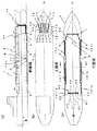
図1は、本発明の一実施形態に係る気泡保持装置を、海洋で使用する船舶に適用した実施例を示す。図1(a)は、当該船舶の側面図を、図1(b)は、その上面図を、図1(c)は下面図を示すもので、一部説明のために要部構成を露出させて表現している。
(First embodiment)
FIG. 1 shows an example in which a bubble holding device according to an embodiment of the present invention is applied to a ship used in the ocean. 1 (a) shows a side view of the ship, FIG. 1 (b) shows a top view thereof, and FIG. 1 (c) shows a bottom view. Let me express.
船舶1の甲板2上に、送気手段としてのブロワー10、11、12、13、14が並べて設置されている。これらのブロワー10、11、12、13、14は甲板2上で、船首で破砕された潮の飛沫を避けるため格納庫に入れられて設置されていて、少しでも飛沫を避ける意味から気体である空気の取り込みを、船体の進行方向の反対側から行っている。
On the
このブロワー10、11、12、13、14は、ルーツ式の容積型ブロワーであり、駆動装置であるインバータ型の電動機60(図示しない)により、ベルトを介してブロワー内部の2つのロータが回転され、ブロワー内壁とロータとの間に取り込まれた空気がロータの回転に伴い圧縮され、供給される構造である(図示しない)。ブロワー10、11、12、13、14は容積型であるため、先での圧力変動があっても安定して決まった量の空気を供給できるものとなっている。また、このルーツ式ブロワーは、同じ容積型であってもピストン式と異なりほぼ連続的に空気の加圧が行われるため脈動が少なく、圧力平滑化のためのタンク等も廃止することが可能である。さらに、回転が滑らかで振動や騒音が少ないため、甲板2上にブロワー10、11、12、13、14が配置されても、下部の船室で共鳴音が発生しにくいものとなっている。
These
ブロワー10、11、12、13、14に取り込まれた空気がそれぞれ加圧され、屈曲部を有した送気管16、17、18、19、20を通って、船底3の近傍に設置された空気噴出口21、22、23、24、25に導かれる。この気体噴出口21、22、23、24、25は、この実施例の場合、船底3の前部平面で船体4の平面中心線CLに対して略対称的に、略一列に配置されている。気体噴出口21、22、23、24、25を船底3に設けることは、噴出した気泡の船底3部への滞在を長引かせ、波等による圧力変動を緩和する狙いからであり、また船底3の前部に設けることは、噴出した気泡を船底3へ極力全体に亘って滞在させる目的からである。
Air taken into the
また、気体噴出口21、22、23、24、25を略一列に配置することは、構成を簡素化し、対応して設けたブロワー10、11、12、13、14や送気管16、17、18、19、20等の配置も容易化するためである。また、空気噴出口21、22、23、24、25は、この例の場合、奇数個の5個としているため、真中の一つ(空気噴出口23)を平面中心線CL上に持ってくることにより、船舶1の直進性を有した上での、気泡の1箇所噴出が実現できる。この場合、空気噴出口21、22、23、24、25は、船体4の平面中心線CLに対して略対称的に、船底3の前部平面形状に沿うように配置されるように構成することが可能である。
In addition, the arrangement of the
船底3には、空気噴出口21、22、23、24、25から噴出された気泡を逃さないように気泡のガイドを行う端板5、5´、6、6´、7、7´がこれも船体4の平面中心線CLに対して対称に配置されている。端板6、6´及び7、7´は、同図上では寸法が略等しく描かれているが、端板7、7´が端板6、6´よりも短い寸法でもよく、端板の数も同図に示すものに限定されるものではない。船底3にはこの他、海水や気泡による船体4に作用する剪断力を検出する剪断力検出器である剪断力センサー50、51、52、53、54が船尾側に設けられている。
The
また、相対速度検出器である相対速度センサー55、56が船尾側に設けられている。船側8には、別の相対速度センサー57が設けられている。これらの相対速度センサー55、56は、空気噴出口21、22、23、24、25から離して、あるいは相対速度センサー57は、近くても船側8の気泡の影響が無い箇所に設けられている。特に、相対速度センサー57は、船側8でも波の影響を受けない下方に設置されている。これらの相対速度センサー55、56、57は、超音波式を採用しており、水中での使用を可能として、波や潮による影響を少なくしている。
In addition,
また、船底3の後部と前部には、噴出された気泡の状態を監視するビデオカメラ58、59が設けられている。このビデオカメラ58、59の撮影した映像を、人が監視し、気泡の噴出状態を解析することに役立てている。
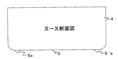
図2は、本発明の一実施形態に係る船体4の(図1の)X−X断面図である。同図に示されるように、端板5、5´及びビルジキール101、101´が配備される。このように、通常、船舶は船行上の安定化を図るため、船底3と船側8の接合部(ビルジ部)に、たとえばビルジキールが配設される。これにより、船舶は波浪や潮流といった自然現象及び衝突物体に対し、横揺れや横転を抑制することができる。また、本発明に係る端板5、5´は、ビルジキール101、101´とは別途配設することができる。配設位置は、ビルジキール101、101´よりも平面中心線CLを基準として内側が好ましい。
FIG. 2 is a cross-sectional view taken along the line XX (of FIG. 1) of the
一方、端板5、5´を、船舶の安定化を図るために用いることもできる。この場合、端板5、5´が安定化機能を担う分、ビルジキール101、101´の安定化に係る性能を変更することもできる。その際には、端板5、5´及びビルジキール101、101´の構造、寸法及び配設位置等、船舶の船行を妨げないことを配慮して設計することが好ましい。なお、端板5、5´に係る本来の目的は、気泡を船底3に保持しつつ流すことであるため、そのことを十分に配慮した端板5、5´及びビルジキール101、101´の設計とする。
On the other hand, the
図3は、本発明の別の一実施形態に係る船体4の(図1の)X−X断面図である。同図には、端板の断面形状を略三角形として構成する場合の態様が示されている。同図に示されるように、端板5a、5´aは船底3を底辺とした略三角形となる形状を有している。図2に係る端板5、5´とは、その形状を異にする点のみが相違するため、その他詳細な説明は省略する。
FIG. 3 is a cross-sectional view taken along the line XX (of FIG. 1) of the
ここで、この略三角形の断面形状と平板の端板5あるいは5’を用いた場合の水との接触面積を比較すると、3角形の2辺の和は1辺より長いことになり、略三角形とすることで水との接触面積が小さくなり、端板を設置することによる摩擦抵抗が低減できる。この略三角形となる形状の端板5a、5´aにより、端板の摩擦抵抗の増加を低減することができる。
Here, when the cross-sectional shape of the substantially triangular shape is compared with the contact area with water in the case where the
図4は、本発明の更に別の一実施形態に係る船体4の(図1の)X−X断面図である。同図には、端板の断面形状を二次関数曲線等の曲線とする場合の態様が示されている。同図に示されるように、端板5b、5´bは船底3を底辺とした二次関数曲線等の曲線となる形状を有している。図2に係る端板5、5´とは、その形状を異にする点のみが相違するため、その他詳細な説明は省略する。この二次関数曲線等の曲線となる形状の端板5a、5´aにより、端板の摩擦抵抗の増加を低減することができる。
FIG. 4 is a cross-sectional view taken along the line XX (of FIG. 1) of the
図5は、本発明の更に別の一実施形態に係る図2の点線Y部の拡大図である。同図には、端板の前部を流線型とする場合の態様が示されている。同図に示されるように、端板5は、平面中心線CLを基準として内側を流線型とする形状が好ましく、船舶の船行を妨げないことを配慮して設計する必要がある。具体的には、端板5の先端は、刀の先端のように表面の角度を微妙に変化させ、刀が物体を切りやすくするために有する形状に類似した形状が好ましい。なお、端板5が船底3に既設されている場合には、流線型に係る部材を端板5に付設してもよい。また、端板の後部も流線型とすることが好ましい(図示しない)。
FIG. 5 is an enlarged view of a dotted line Y portion of FIG. 2 according to still another embodiment of the present invention. The figure shows a mode in which the front part of the end plate is streamlined. As shown in the figure, the
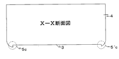
図6は、本発明の更に別の一実施形態に係る船体4の(図1の)X−X断面図である。同図には、船底3に凹部を形成した場合の態様が示されている。同図に示されるように、図2に示す端板5、5´の代わりに、端部5c、5´cを残し、その他の部分を切削する構成、若しくは端部5c、5´cを有する凹部に係る形状部材を配設する構成、又は端部5c、5´cを既設の船底3に付設する構成、又は船底3そのものを凹部を有した構成とする。端部5c、5´cの前部は、図5に示すような流線型としてもよい。なお、図2に係る端部5、5´とは、その形状を異にする点のみが相違するため、その他詳細な説明は省略する。この端部5c、5´c及びこの端部間に挟まれる凹部により、気泡を船底に保持しつつ流すことが可能となる。
FIG. 6 is a cross-sectional view taken along the line XX (of FIG. 1) of the
図7は、本発明の更に別の一実施形態に係る船体4の(図1の)X−X断面図である。同図には、船底3に凹部を形成した場合の態様が示されている。同図に示されるように、図2に示す端板5、5´の代わりに、端部5d、5´dを残し、その他の部分を切削する構成、若しくは端部5d、5´dを有する凹部に係る形状部材を配設構成、又は端部5d、5´dを既設の船底3に付設する構成とする。図6に係る態様とは、二次曲線とする部分において、その形状を異にする。端部5d、5´dの前部は、図5に示す流線型としてもよい。なお、図2に係る端部5、5´とは、その形状を異にする点のみが相違するため、その他詳細な説明は省略する。この端部5d、5´d及びこの端部間に挟まれる凹部により、気泡を船底に保持しつつ流すことが可能となる。
FIG. 7 is a cross-sectional view taken along the line XX (of FIG. 1) of the
次に、本発明の一実施形態に係る気泡保持装置の動作及び使用方法について、概念図を用いて説明する。 Next, operation | movement and the usage method of the bubble holding | maintenance apparatus which concern on one Embodiment of this invention are demonstrated using a conceptual diagram.
図8は、本発明の一実施形態に係る端板5、5´の配設時の気泡保持状態を示す概念図である。同図においては、船舶が傾いたときの気泡の保持状態を説明している。この場合、図1のX−X断面において、船舶の傾きにより船底3の両端部に差圧が生じ、圧力の低いほうへ気泡は移動する。これにより、気泡は船底3の範囲外に拡散するため、気泡による摩擦低減効果が低減してしまう。これに対し本願では、端板5、5´を船底3の両端部に配設することで、気泡の拡散を抑制する。具体的には、気泡は圧力の高いほうから低いほうへ移動するものであり、低いほうから高いほうへの移動は不可能である。したがって、気泡は圧力の低いほうへ移動するためには、端板5に係る障壁を迂回しなければならず、そのためには圧力の高いほうへ移動することを要するため、前述の原理により、気泡は船底3に保持されることとなる。傾きが逆の場合も同様である。また、同図ほどの傾きがないとしても、船航中の微妙な横揺れ等により気泡は微小な差圧を感知し、同様にして気泡が圧力の低いほうへ移動してしまうが、端板5により気泡の移動による拡散を抑制し、端板5の終端地点まで保持されつつ流れる。これにより、波や流れ等の外乱時や旋回する際に生じる船舶の傾きにも気泡が保持され有効に摩擦抵抗の低減が図れる。
FIG. 8 is a conceptual diagram showing a bubble holding state when the
図9は、本発明の一実施形態に係る前部及び後部を流線型とする端板5、5´に係る配設時の船舶船航中の気泡流動状態を示す概念図である。同図においては、端板5、5´の前部を、中心線を基準として対称となる形状とすることにより、端板5、5´は船舶の船航を妨げる抵抗体となることを極力回避できる。また、端板5、5´の後部は、中心線を基準として水深の深い方の後部からなだらかな湾曲又は傾斜を有して水深の浅い方の後部を終端する流線形状を有することにより、気泡は端板5、5´の後部に係る終端地点を境にして急激に保持状態が解除されるのではなく、後部に係る緩やかな湾曲又は傾斜の始点を境に端板5、5´の寸法が小さくなり、かかる形状により気泡の保持状態は緩やかに解除されるため、気泡は水中に徐々に拡散していく。また、後部を開くように形成することにより、船底を十分に覆って流れてきた気泡が、外側に向かう流れとなり、船尾に設けたプロペラ(図示せず)への気泡の巻きこみを無くし、推進力が落ちることを防止できる。
FIG. 9 is a conceptual diagram showing a bubble flow state during marine vessel navigation at the time of disposition related to the
図10は、本発明の更に別の一実施形態に係り、船底3を断面視で三角形に係る凹凸状とした船舶の船航中に係る気泡保持状態を示す断面概念図である。同図において、船底3の断面を三角形に係る凹凸形状とした場合、気泡は凹凸断面に係る船底3を底辺とする隣り合う第一の三角形状と第二の三角形状にて勾配が形成され、かかる勾配にて発生する差圧により、気泡は圧力の低いほうへ移動する。また、一つの三角形断面に取りこまれた気泡は、三角形の頂点を乗り越えるには抵抗があることから、抵抗の少ない長手方向に沿って船尾の方へ流れる。これにより、船舶船航中に発生する船体の傾きにて発生する差圧または微妙な横揺れ等により生じる微小な差圧によっても、気泡の移動及び拡散は抑制され、気泡は船底3に保持されつつ流れる。なお、船底3を底辺とする三角形の高さ寸法は船底3を基準として10mm以下とすることが好ましいが、この考え方の基本は、三角形の高さが、気泡に十分覆われる高さ以下に形成されることである。すなわち、船底3を底辺とする三角形の高さ寸法は船底3を基準として10mm以下に限定されることはなく、気泡に十分覆われる程度の高さであればよい。
FIG. 10 is a conceptual cross-sectional view showing a bubble holding state during the navigation of a ship according to still another embodiment of the present invention. In the same figure, when the cross-section of the
図11は、本発明の更に別の一実施形態に係り、船底3に断面視で翼断面型マウンドを有する構成とした船舶の船航中に係る気泡保持状態を示す断面概念図である。同図において、船舶の進行方向とは逆向きに水が流れるが、同様にして気泡も水流の向きに流れる。一方、下流に流れるに従って、気泡は水中で拡散するため、気泡による摩擦低減効果が低減する。しかし、船底3に翼断面型マウンド102を配設することで、気泡を再び船底3に付随させて摩擦低減効果を増進させることができる。具体的には、気泡は翼断面型マウンド102の形状に従って流動する。翼断面型マウンド102の形状に従って気泡が流動するには、翼断面型マウンド102の表面形状を断面視で緩やかな湾曲を有する形状とする必要がある。翼断面型マウンド102の始端部分が緩やかではない角度を有する場合、翼断面型マウンド102の表面が障壁となり、気泡が衝突時点で拡散してしまうおそれがあるからである。また、翼断面型マウンド102の終端部分が緩やかでない角度を有する場合、気泡は終端部と船底3との勾配により発生する差圧により、急激に船底3に係る低圧部に移動することとなり、かかる形状により船底3に気泡が付随しない部分ができてしまうからである。したがって、このような形状を有する翼断面型マウンド102にて発生する差圧を利用して、気泡の拡散を抑制し、摩擦低減効果の増進を実現することができる。
FIG. 11 is a conceptual cross-sectional view showing a bubble holding state during the navigation of a ship having a structure in which the
図12は、本発明の更に別の一実施形態に係り、船底3を断面視で後部に向かい緩やかな段差を有する構成とした船舶の船航中に係る気泡保持状態を示す断面概念図である。同図において、上記と同様、船舶の進行方向とは逆向きに水が流れるが、同様にして気泡も水流の向きに流れる。一方、下流に流れるに従って、気泡は水中で拡散するため、気泡による摩擦低減効果が低減する。しかし、船底3が断面視にて後部に向かい緩やかな段差を有することで、気泡を再び船底3に付随させて摩擦低減効果を増進させることができる。具体的には、第一の段差と第二の段差の形状による流体力作用により、気泡の拡散を抑制し、摩擦低減効果を維持することができる。なお、上記と同様、段差の終端部は緩やかな湾曲形状を有する必要がある。かかる形状でない場合、気泡は第一の段差に係る終端部と第二の段差に係る始端部との勾配により発生する差圧により、急激に船底3に係る低圧部に移動することとなり、段差又は船底3に気泡が付随しない部分ができてしまうからである。
FIG. 12 is a conceptual cross-sectional view showing a state of holding bubbles during ship navigation, in which the
(第2の実施形態)
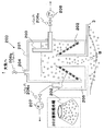
図13Aは、本発明の第2の実施形態に係る気泡保持装置における気液分離器200の構成を説明するための断面図である。同図に示されるように、気液分離器200は、本体201、気泡分離促進フィルター202、気体移送菅203、気体開放口204、液体移送部205、バルブ206a、206b及び206cを備えて構成される。なお、気液分離器200は水上置換法の原理を応用している。また、図13B及び図13Cは、本発明の第2の実施形態に係る気泡保持装置における気液分離器200の使用方法を示す概念図である。
(Second Embodiment)
FIG. 13A is a cross-sectional view for explaining the configuration of the gas-
本体201は、水分吸込口Bを有し、常時開口している。また、本体201は、その内部において、気泡分離促進フィルター202を介して液体と気体が分離される機能を有する。気泡分離促進フィルター202は、水分吸込口を有する空洞状の円柱を囲む円錐形状を有し、フィルターが円錐状に形成されている。気体移送菅203は、一方の開口部を本体201の内部に、他方の開口部を本体201の外部に、それぞれ配置させた構成とする。ブロワー208は、外部に係る開口部からバルブ206aを介して吸気する機能を有している。このブロワー208は、水が混入しても空気を送れる構成が好ましい。本体201の上部には、気体開放口204を設け、バルブ206bを介して不要な気体を大気へ開放できる構成とする。一方、本体201内部で気泡分離促進フィルター202を境界として液体移送部205を設け、バルブ206cを介して、ポンプ207にて吸水できる構成とする。
The
次に、図14は本発明の第2の実施形態に係る気泡保持装置における気液分離器200の使用に係る状況図である。同図内の(a)(以下、「(a)」ともいう。)は、本発明の一実施形態に係るブロワー10、11、12、13、14にて送気したときの摩擦低減効果を表す概念図である。同図において、横軸は距離を示し、縦軸は摩擦低減効果を0.0から1.0の間で数値化したもので、1.0が摩擦力の最大値、0.0が摩擦力の最小値(摩擦無し)を示す。また、同図内の(b)(以下、「(b)」ともいう。)は、本発明の一実施形態に係るブロワー10、11、12、13、14にて送気後の水中での気泡拡散状態を示す図である。同図において、水流は図面の左から右の方向とする。(a)と(b)は対応関係にあるため、以降は随時両図及び図13Aを用いながら説明する。
Next, FIG. 14 is a situation diagram related to the use of the gas-
まず(b)に示すとおり、空気噴出口20を介して噴出された空気は、船底3近傍を漂う。そのため(a)にて、摩擦低減効果により摩擦がほとんど無い状態であることが確認できる。しかし、(b)にて、気泡は一度噴出されると水流にのって移動するため、気泡は水中で拡散し、船底3近傍から離れる。そのため(a)にて、摩擦低減効果が急激に減少(摩擦力が急激に上昇)し、その後一定の割合で摩擦力が上昇する(数値が0.0から1.0に近づく状態)。これはまた、気泡と船底3の間に水分が浸入するために発生する現象であるとも考えられる。したがって、(b)にて、空気噴出口20を基準として船尾方向(水流の下流方向)の船底3に、気泡が拡散してしまう前(船底3から気泡が約5〜7mm離れるとき)に、侵入した水分を吸い込む水分吸込口Bを設け、水分吸込口Bを介し、図13Aに示す気液分離器200により水分を少し吸い込む。これにより、気泡を船底3近傍に再び引き付けるため、(a)にて、水分吸込み直後に摩擦力が急激に低下し、摩擦低減効果が回復する。吸込み後は、再び気泡は水中を拡散するために、摩擦力が緩やかに上昇する。
First, as shown in (b), the air ejected through the
以降、図13A、図13B及び図13Cを用いて、本発明の一実施形態に係る気泡保持装置に係る気液分離器200の動作及び使用方法について説明する。なお、図13Aに係る気液分離器200は、図13B及び図13Cに係る気液分離器を裏面から見た断面を示したものである。したがって、図13B及び図13Cと図13Aとでは左右が逆になっている。
Hereinafter, the operation and usage method of the gas-
図13Aに示すとおり、水分吸込口Bは常時開口されている。したがって、水分は水分吸込口Bを介して気液分離器200に係る本体201内部に浸水する構造となる。このとき、ポンプ207の吸水により、本体201内の水を回収することができる。回収する際、気泡分離促進フィルター202は、水に含まれる気体と液体を分離させるため、液体のみを液体移送部205を経由させて回収することができる。回収した水分は、船舶のエンジンの冷却水として利用することができる。なお、バルブ206cの開閉により吸水の有無を操作することもでき、ポンプ207を常時駆動させていてもよい。一方、気泡分離促進フィルター202により分離された気体は、ブロワー208の吸気により、気体移送菅203を経由させて回収することができる。なお、バルブ206aの開閉により吸気の有無を操作することもでき、ブロワー208を常時駆動させていてもよい。
As shown in FIG. 13A, the moisture inlet B is always open. Therefore, the moisture is immersed in the
したがって、図13Bに示すとおり、ブロワー208にて吸気した気体を大気に開放し、かつ、本体201内の気体をバルブ206bを介して大気に開放することで、気液分離器200は気体を船底3近傍に再び引き付けることができる。また、図13Cに示すとおり、ブロワー208にて吸気した気体を、回収空気噴出口Cを介して再噴出することで、摩擦低減効果を増幅させることもできる。
Therefore, as shown in FIG. 13B, the gas-
なお、本発明は上述した実施形態に限定されるものではなく、本発明の主旨を逸脱しない範囲内で種々変更して実施することが可能である。 Note that the present invention is not limited to the above-described embodiment, and various modifications can be made without departing from the spirit of the present invention.
また、上述した実施例は、本発明に係る技術思想を具現化するための実施形態の一例を示したにすぎないものであり、他の実施形態でも本発明に係る技術思想を適用することが可能である。 Further, the above-described examples are merely examples of embodiments for embodying the technical idea according to the present invention, and the technical ideas according to the present invention can be applied to other embodiments. Is possible.
本発明に係る船舶の摩擦抵抗低減装置は、一般的に海洋での使用に限らず、河川、湖水等あらゆる水系で利用される船舶で使用することが可能である。 The ship frictional resistance reducing device according to the present invention is not limited to use in the ocean, but can be used in ships used in all water systems such as rivers and lakes.
また、船舶の形を取らない、水系での航行体、浮体に広く適用でき、摩擦抵抗の低減による省エネルギー効果の貢献をはじめ、回収水の利用等の利便性の面でも広く社会全般、各種産業全般に対して大きな有益性をもたらすものである。 In addition, it can be widely applied to navigating bodies and floating bodies in water systems that do not take the shape of a ship, and contributes to energy saving effects by reducing frictional resistance, and is also widely used in general society and various industries in terms of convenience such as use of recovered water It brings great benefits to the whole.
1…船舶、3…船底、10、11、12、13、14…ブロワー(送気手段)、21、22、23、24、25…空気噴出口、60…電動機(駆動装置)、200、201…気液分離器、202…気泡分離促進フィルター、203…気体移送菅、204…気体開放口、205…液体移送部、206…バルブ(気体調節手段)、B…水分吸込口、C…回収空気噴出口
DESCRIPTION OF
Claims (4)
Priority Applications (12)
| Application Number | Priority Date | Filing Date | Title |
|---|---|---|---|
| JP2008100894A JP5311541B2 (en) | 2008-04-08 | 2008-04-08 | Ship bubble holding device |
| CN201510142862.2A CN105501388A (en) | 2008-04-01 | 2009-03-31 | Frictional resistance reduction device for ship |
| CN201510142863.7A CN106005241B (en) | 2008-04-01 | 2009-03-31 | The frictional resistance of ship reduces device |
| KR1020107024441A KR101414883B1 (en) | 2008-04-01 | 2009-03-31 | Frictional resistance reduction device for ship |
| EP09727111.8A EP2272747B1 (en) | 2008-04-01 | 2009-03-31 | Frictional resistance reduction device for ship |
| US12/935,624 US9376167B2 (en) | 2008-04-01 | 2009-03-31 | Frictional resistance reduction device for ship |
| KR1020147008399A KR101482918B1 (en) | 2008-04-01 | 2009-03-31 | Frictional resistance reduction device for ship |
| DK09727111.8T DK2272747T3 (en) | 2008-04-01 | 2009-03-31 | DRAWING RESISTANCE REDUCTION DEVICE FOR SHIP |
| EP18190132.3A EP3441298A1 (en) | 2008-04-01 | 2009-03-31 | Frictional resistance reduction device for ship |
| CN200980112221.5A CN101990511B (en) | 2008-04-01 | 2009-03-31 | Frictional resistance reduction device for ship |
| KR1020147008398A KR20140047167A (en) | 2008-04-01 | 2009-03-31 | Frictional resistance reduction device for ship |
| PCT/JP2009/001520 WO2009122736A1 (en) | 2008-04-01 | 2009-03-31 | Frictional resistance reduction device for ship |
Applications Claiming Priority (1)
| Application Number | Priority Date | Filing Date | Title |
|---|---|---|---|
| JP2008100894A JP5311541B2 (en) | 2008-04-08 | 2008-04-08 | Ship bubble holding device |
Related Child Applications (3)
| Application Number | Title | Priority Date | Filing Date |
|---|---|---|---|
| JP2013137342A Division JP5787263B2 (en) | 2013-06-28 | 2013-06-28 | Ship bubble holding device |
| JP2013137341A Division JP2013216323A (en) | 2013-06-28 | 2013-06-28 | Air bubble holding device of ship |
| JP2013137343A Division JP5799982B2 (en) | 2013-06-28 | 2013-06-28 | Ship bubble holding device |
Publications (2)
| Publication Number | Publication Date |
|---|---|
| JP2009248832A JP2009248832A (en) | 2009-10-29 |
| JP5311541B2 true JP5311541B2 (en) | 2013-10-09 |
Family
ID=41309920
Family Applications (1)
| Application Number | Title | Priority Date | Filing Date |
|---|---|---|---|
| JP2008100894A Expired - Fee Related JP5311541B2 (en) | 2008-04-01 | 2008-04-08 | Ship bubble holding device |
Country Status (1)
| Country | Link |
|---|---|
| JP (1) | JP5311541B2 (en) |
Families Citing this family (7)
| Publication number | Priority date | Publication date | Assignee | Title |
|---|---|---|---|---|
| JP5729913B2 (en) * | 2010-04-01 | 2015-06-03 | 三菱重工業株式会社 | Friction resistance reduction type ship |
| JP5631039B2 (en) * | 2010-04-01 | 2014-11-26 | 三菱重工業株式会社 | Propeller vibration reduction device |
| JP5675148B2 (en) * | 2010-04-02 | 2015-02-25 | 三菱重工業株式会社 | Ship resistance reduction device |
| KR101471229B1 (en) * | 2010-11-29 | 2014-12-09 | 현대중공업 주식회사 | Air-cavity with protective structure against cavitation |
| KR101224311B1 (en) * | 2011-01-19 | 2013-01-21 | 현대중공업 주식회사 | Air-cavity by attachable and detachable wall |
| JP6085474B2 (en) * | 2012-12-25 | 2017-02-22 | 三菱重工業株式会社 | Gas-liquid separator and ship |
| JP2024004668A (en) * | 2022-06-29 | 2024-01-17 | 日立Geニュークリア・エナジー株式会社 | Boiling-water reactor steam dryer |
Family Cites Families (4)
| Publication number | Priority date | Publication date | Assignee | Title |
|---|---|---|---|---|
| JPS5078092A (en) * | 1973-11-13 | 1975-06-25 | ||
| JPS62143595U (en) * | 1986-03-05 | 1987-09-10 | ||
| JP2000219188A (en) * | 1999-01-29 | 2000-08-08 | Yamaha Motor Co Ltd | Divided-type bilge keel and small boat having it |
| JP2000296797A (en) * | 1999-04-14 | 2000-10-24 | Ishikawajima Harima Heavy Ind Co Ltd | Friction resistance reduced ship |
-
2008
- 2008-04-08 JP JP2008100894A patent/JP5311541B2/en not_active Expired - Fee Related
Also Published As
| Publication number | Publication date |
|---|---|
| JP2009248832A (en) | 2009-10-29 |
Similar Documents
| Publication | Publication Date | Title |
|---|---|---|
| JP5311541B2 (en) | Ship bubble holding device | |
| JP5311540B2 (en) | Air bubble entrainment prevention device for ships | |
| JP5604736B2 (en) | Ship frictional resistance reduction device | |
| US9855996B2 (en) | Air lubrication system and vessel comprising such a system | |
| US5524568A (en) | Air bubble lubricated boat hull | |
| WO2009122736A1 (en) | Frictional resistance reduction device for ship | |
| US8327784B2 (en) | Apparatus for generating and distributing compressed air for reducing drag | |
| US8763547B2 (en) | Apparatus for lowering drag on a moving nautical vessel | |
| WO2008005336A2 (en) | Monohull fast ship or semi-planing monohull with a drag reduction method | |
| JP3190753B2 (en) | Small high-speed ship | |
| JP4925683B2 (en) | Water jet propulsion ship | |
| JP5599482B1 (en) | Ship equipped with bubble resistance reduction device and ship resistance reduction method | |
| JP5799982B2 (en) | Ship bubble holding device | |
| US7685958B2 (en) | Ship bow | |
| JP5975363B2 (en) | Hull fluid resistance reduction device | |
| JP5787263B2 (en) | Ship bubble holding device | |
| JP5697000B2 (en) | Ship frictional resistance reduction device | |
| JP2013216323A (en) | Air bubble holding device of ship | |
| JP2001278178A (en) | Method of reducing frictional resistance of hull, and frictional resistance reduced ship | |
| KR20020020624A (en) | Method of reducing frictional resistance of a hull, and frictional resistance reducing vessel | |
| JP5806251B2 (en) | Ship equipped with bubble resistance reduction device and ship resistance reduction method | |
| CA3066452A1 (en) | Boat hull design for outboard jet motor | |
| JP2013224145A (en) | Frictional resistance reducing device of ship | |
| JP5669114B2 (en) | Ship frictional resistance reduction device | |
| JP2002079986A (en) | Ship reduced in friction resistance |
Legal Events
| Date | Code | Title | Description |
|---|---|---|---|
| A621 | Written request for application examination |
Free format text: JAPANESE INTERMEDIATE CODE: A621 Effective date: 20110224 |
|
| A131 | Notification of reasons for refusal |
Free format text: JAPANESE INTERMEDIATE CODE: A131 Effective date: 20121009 |
|
| A521 | Request for written amendment filed |
Free format text: JAPANESE INTERMEDIATE CODE: A523 Effective date: 20121210 |
|
| TRDD | Decision of grant or rejection written | ||
| A01 | Written decision to grant a patent or to grant a registration (utility model) |
Free format text: JAPANESE INTERMEDIATE CODE: A01 Effective date: 20130528 |
|
| A61 | First payment of annual fees (during grant procedure) |
Free format text: JAPANESE INTERMEDIATE CODE: A61 Effective date: 20130628 |
|
| R150 | Certificate of patent or registration of utility model |
Ref document number: 5311541 Country of ref document: JP Free format text: JAPANESE INTERMEDIATE CODE: R150 Free format text: JAPANESE INTERMEDIATE CODE: R150 |
|
| S533 | Written request for registration of change of name |
Free format text: JAPANESE INTERMEDIATE CODE: R313533 |
|
| R350 | Written notification of registration of transfer |
Free format text: JAPANESE INTERMEDIATE CODE: R350 |
|
| S533 | Written request for registration of change of name |
Free format text: JAPANESE INTERMEDIATE CODE: R313533 |
|
| R350 | Written notification of registration of transfer |
Free format text: JAPANESE INTERMEDIATE CODE: R350 |
|
| R250 | Receipt of annual fees |
Free format text: JAPANESE INTERMEDIATE CODE: R250 |
|
| R250 | Receipt of annual fees |
Free format text: JAPANESE INTERMEDIATE CODE: R250 |
|
| LAPS | Cancellation because of no payment of annual fees |