JP5308158B2 - Molded reamer tooth and manufacturing method thereof - Google Patents
Molded reamer tooth and manufacturing method thereof Download PDFInfo
- Publication number
- JP5308158B2 JP5308158B2 JP2008537212A JP2008537212A JP5308158B2 JP 5308158 B2 JP5308158 B2 JP 5308158B2 JP 2008537212 A JP2008537212 A JP 2008537212A JP 2008537212 A JP2008537212 A JP 2008537212A JP 5308158 B2 JP5308158 B2 JP 5308158B2
- Authority
- JP
- Japan
- Prior art keywords
- cutting
- edge
- teeth
- reamer
- straight
- Prior art date
- Legal status (The legal status is an assumption and is not a legal conclusion. Google has not performed a legal analysis and makes no representation as to the accuracy of the status listed.)
- Active
Links
Images


Classifications
-
- A—HUMAN NECESSITIES
- A61—MEDICAL OR VETERINARY SCIENCE; HYGIENE
- A61B—DIAGNOSIS; SURGERY; IDENTIFICATION
- A61B17/00—Surgical instruments, devices or methods, e.g. tourniquets
- A61B17/16—Bone cutting, breaking or removal means other than saws, e.g. Osteoclasts; Drills or chisels for bones; Trepans
- A61B17/1662—Bone cutting, breaking or removal means other than saws, e.g. Osteoclasts; Drills or chisels for bones; Trepans for particular parts of the body
- A61B17/1664—Bone cutting, breaking or removal means other than saws, e.g. Osteoclasts; Drills or chisels for bones; Trepans for particular parts of the body for the hip
- A61B17/1666—Bone cutting, breaking or removal means other than saws, e.g. Osteoclasts; Drills or chisels for bones; Trepans for particular parts of the body for the hip for the acetabulum
Abstract
Description
(関連出願の相互参照)
本件は、アメリカ合衆国において2005年10月24日に出願されたフェールバウム(Fehlbaum)とレショット(Lechot)による米国特許出願番号11/257,417“Contour Reamer Teeth and Method of Manufacture”の継続出願であり、また2004年7月7日に出願されたレショットによる米国特許出願番号10/500,944“Contour Reamer Teeth”の一部継続出願であり、その双方を参照として組み入れ、本件開示と一致する点において依存するものである。
(Cross-reference of related applications)
This is a continuation of US Patent Application No. 11 / 257,417 “Contour Reamer Teeth and Method of Manufacture” by Fehlbaum and Lechot, filed October 24, 2005 in the United States. And a continuation-in-part of US patent application Ser. No. 10 / 500,944 “Contour Reamer Teeth” filed on July 7, 2004, both of which are incorporated by reference and consistent with the present disclosure. It depends on.
本願発明は、外科用製品に関し、詳細には骨に成形穴を切削するための外科用リーマに関する。 The present invention relates to a surgical product, and in particular, to a surgical reamer for cutting a molded hole in a bone.
滑らかな壁面と正確な形状を要する股関節インプラントのために骨に穴を成形するには、リーマシェル又は切削カップは半球形であることが好ましい。さらに、切削歯は的確に配置及び配向される必要がある。また、歯の高さは、股関節の骨の大きさを決める上で、ひいてはリーマによる穴成形の精度を決める上で重要となる。 To form a hole in the bone for a hip implant that requires a smooth wall and precise shape, the reamer shell or cutting cup is preferably hemispherical. Furthermore, the cutting teeth need to be placed and oriented accurately. In addition, the height of the teeth is important in determining the size of the hip joint bone and, in turn, in determining the accuracy of hole forming by the reamer.
多くの場合、腰関節のインプラントは凹状で半球形の穴に取り付けられるのが最も良いとされている。しかし、このような形状は必ずしも必要とは限らない。他の寛骨臼を切削するためのシェルは半球形ではなく、本願において説明する原理はそのような他の形状を包含するように適用されてもよい。 In many cases, hip implants are best fitted in concave, hemispherical holes. However, such a shape is not always necessary. The shell for cutting other acetabulums is not hemispherical, and the principles described herein may be applied to encompass such other shapes.
特にセメントを用いない股関節手術では、骨と最終的な(半球形の)インプラントとの接触が最小限にとなるように、寛骨臼が通常半球形の正確な形状にリーマで切削されることが以前にも増して重要視されている。 Especially in hip surgery without cement, the acetabulum is usually reamed to the correct shape of a hemisphere so that the contact between the bone and the final (hemispheric) implant is minimized. Is more important than ever.
また、患者のトラウマを軽減し回復のスピードを早めるために、切開部をより小さくすることにますます重点が置かれるようになった。これらのさらなる要件によって、医療器具及びインプラントの設計士たちはさらなる挑戦と向き合うこととなった。さらに、現在では外科医は寛骨臼リーマの取手部を“スイーピング(sweeping)”と呼ばれる方法で器具取手部の端部を角度をつけて旋回し、リーマが切削する軸を常に変化させて使用するよりも、単独の軸で保持して使用するケースが多くなっていることも、外科手術の工程における変化の一つとして挙げられる。実験として、従来技術のリーマ取手部を一定の軸で保持して使用すると、マクロスケールではおおよそ半球体をなす一連のコンセントリック・リングが切削される。一方、外科医がリーマ取手部の軸を“スイープ”、すなわち旋回するように動かすと、(研磨と同様の効果により)上記の不具合は解消され、半球形の表面が形成される。 Increasing emphasis has also been placed on smaller incisions to reduce patient trauma and speed recovery. These additional requirements have led medical device and implant designers to face further challenges. In addition, surgeons now use the acetabular reamer's handle with an angled angle at the end of the instrument handle in a method called “sweeping”, constantly changing the axis the reamer cuts. In addition, the fact that there are more cases of holding and using a single shaft is one of the changes in the surgical process. As an experiment, when a conventional reamer handle is held on a fixed axis, a series of concentric rings, which are roughly hemispherical, are cut on a macro scale. On the other hand, if the surgeon moves the axis of the reamer handle to “sweep”, that is, pivot, the above problems are eliminated (by a similar effect to polishing) and a hemispherical surface is formed.
“スイーピング”を行わずに滑らかな半球形の表面を得るために、コンセントリック・リングの数を増やし、びびり/振動を軽減するには、より多くの歯を設けることが好ましい。しかし、その場合機械的強度が下がってしまう。また、例えばウェイガンド(Weigand)による米国特許第4023572号に開示されるような従来の“チーズ削り器”タイプのリーマでは、確実に各歯の切削プロファイルを重なるようにし、切削方向に対して歯を的確に配置することがより困難であった。従来のような形状の歯をより大きくしたものの使用も試みられたが、切削片のサイズ及び切削にかかる応力が大きくなりすぎるか、もしくはリーマが複雑すぎるものとなった。また、大きな歯に隣接する開口部も自ずと大きくなるため、少なくともある程度の機械的強度が犠牲となった。 In order to increase the number of concentric rings and reduce chatter / vibration, it is preferable to have more teeth to obtain a smooth hemispherical surface without "sweeping". However, in that case, the mechanical strength is lowered. In addition, a conventional “cheese shaver” type reamer as disclosed, for example, in US Pat. No. 4,022,572 by Weigand ensures that the cutting profiles of each tooth overlap so that the teeth are aligned with respect to the cutting direction. It was more difficult to place accurately. Although attempts have been made to use teeth having larger shapes as in the prior art, the size of the cutting piece and the stress applied to the cutting are too large, or the reamer is too complicated. In addition, the opening adjacent to the large tooth is naturally large, so at least some mechanical strength is sacrificed.
セイラー(Sayler)による米国特許第5116165号には、限定された数の離散的に配置された刃状の歯を有するスクレーパー(掻器)タイプのリーマが開示される。このリーマの歯は、切削される形状のプロファイルを有する単一の曲線によって定義される。すなわち、これら歯は本質的に直線的である。このような歯の形状は、リーミングにおいてときおり生じる異常に高い切削応力がかかった際に、(歯自身の他に)歯の形状を維持するための構造が何一つ備わっていない。また、限られた数のスリット又は溝がリーマの球状の本体に外延的に施された場合、リーマの球状の形状が有する整合性に影響が生じる場合もある。整合性への影響は、スリットの比較的鋭利な角において高い応力が生じることによるものである。 US Pat. No. 5,116,165 to Sayler discloses a scraper type reamer having a limited number of discretely arranged blade-like teeth. The reamer tooth is defined by a single curve with a profile of the shape to be cut. That is, these teeth are essentially straight. Such a tooth shape does not have any structure for maintaining the tooth shape (in addition to the tooth itself) when the unusually high cutting stresses that sometimes occur in reaming are applied. In addition, when a limited number of slits or grooves are extended on the spherical body of the reamer, the consistency of the spherical shape of the reamer may be affected. The effect on consistency is due to high stresses occurring at the relatively sharp corners of the slit.
セイラーによる米国特許第6730094号には、限られた数の離散的に配置された刃状の歯を有するスクレーパータイプのリーマの別の具体案が開示される。このリーマの歯も、また直線的である。このような歯の形状もまた、リーミングにおいてときおり生じる異常に高い切削応力がかかった際に、(歯自身の他に)歯の形状を維持するための構造が何一つ備わっていない。また、その孔部の形状によって、刃の外縁部の、刃の後方に位置する支持部がシェルに移行する箇所で、望ましくない鉤裂や裂傷が生じる。このような形状は、使用時においては接触する軟組織を過失的に裂傷してしまうこともある。裂傷を最も生じやすいと思われる具体案が示されたセイラーの件の図9の場合も、同様のことが言える(外見上は、溝40は歯によって視界から隠れている)。
U.S. Pat. No. 6730094 to Sailer discloses another embodiment of a scraper-type reamer having a limited number of discretely arranged blade-like teeth. The reamer's teeth are also straight. Such tooth shapes also lack any structure to maintain the tooth shape (in addition to the teeth themselves) when subjected to unusually high cutting stresses that sometimes occur in reaming. Also, depending on the shape of the hole, undesirable ruptures and lacerations occur at the outer edge of the blade where the support located behind the blade moves to the shell. Such a shape may accidentally lacerate the soft tissue in contact during use. The same can be said for the case of FIG. 9 in the case of Sailor, where a specific idea that is most likely to cause a laceration (appearingly, the
多くの場合リーマに施される歯の形状は、原材の形状、シート材料、半球体の底面直径又は製造方法に依存する。そして、切削される面の形状については通常考慮されず、このため、歯は望ましい球体又は半球体に近似する形状にしか切削できない場合が多い。例えば、表面が平面的に形成されたり、必要とされるものと異なる半径で形成されたり、全体としていびつな半球が形成される。 In many cases, the shape of the teeth applied to the reamer depends on the shape of the raw material, the sheet material, the bottom diameter of the hemisphere or the manufacturing method. Then, the shape of the surface to be cut is not usually considered, and for this reason, the teeth can only be cut into a shape that approximates a desirable sphere or hemisphere. For example, the surface may be formed planarly, formed with a radius different from that required, or may form a distorted hemisphere as a whole.
従って、必要とされるのは、最終的な切削面を縮小することが可能で、定義された単一の幾何学からなる一連の切削部を形成することが可能なリーマである。また、切削歯を的確に配置及び配向することが可能な機構が求められる。さらに、原材の形状にかかわらず制御が可能となる歯の形状が必要とされる。 Therefore, what is needed is a reamer that can reduce the final cutting surface and form a series of cuts of a single defined geometry. Moreover, a mechanism capable of accurately arranging and orienting cutting teeth is required. Furthermore, a tooth shape that can be controlled regardless of the shape of the raw material is required.
上記の問題点は、必要に応じた形状に切削可能で、且つ一連の二重に湾曲してなる切削歯が、各歯にかかる切削応力を大幅に低減し、切削時に生じる切削片の大きさを縮小することが可能な数だけ配置されてなる切削シェルを有する寛骨臼リーマを提供することによって解消することができる。略全ての歯は、十分な長さの整合する円弧状の切削刃を有し、これらの切削刃は切削される形状のプロファイルと概ね一致する切削プロファイルを有する。 The above problems are that the cutting teeth that can be cut into the required shape and that are a series of double-curved cutting teeth greatly reduce the cutting stress applied to each tooth, and the size of the cutting piece generated during cutting Can be overcome by providing an acetabular reamer having cutting shells arranged in a number that can be reduced. Nearly all teeth have a sufficient length of matching arcuate cutting edges, which have a cutting profile that generally matches the profile of the shape to be cut.
その利点としては、本発明のような構造によると、ある形状を切削するために要する歯の数を、標準的な“チーズ削り器”タイプのリーマと比べて約30%削減することができる。さらなる利点としては、切削刃が形成される孔部は非円形なので、これにより切削刃を形成する器具を正確に配置可能とするインデックス面(indexing surface)が形成される。また、従来のスクレーパータイプのリーマと比べてより小さな歯を、よりたくさん打ち出す又は形成することによって、リーマの半球形状を維持しやすくなる。 As an advantage, a structure such as the present invention can reduce the number of teeth required to cut a shape by about 30% compared to a standard “cheese cutter” type reamer. As a further advantage, since the hole in which the cutting blade is formed is non-circular, this forms an indexing surface that allows the tool forming the cutting blade to be accurately positioned. Moreover, it becomes easy to maintain the hemispherical shape of the reamer by firing or forming a larger number of smaller teeth as compared with the conventional scraper type reamer.
さらなる利点は、上記のように本発明の切削刃の品質及び配向が改善されたことで、より少ない歯を用いてより良好な切削面を形成することが可能となる。 A further advantage is that, as described above, the quality and orientation of the cutting blade of the present invention is improved, so that a better cutting surface can be formed with fewer teeth.
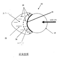
図1には、従来技術による典型的な寛骨臼リーマ10が開示される。リーマ10は、孔部18に隣接して歯16が設けられた表面14を定義する切削カップ又はシェル12を有してなる。底面部20は器具連結装置として形成される(図示なし)。
FIG. 1 discloses a typical
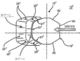
図2aには、リーマ10の歯16が示される。歯16には、切削刃20を支持する分岐面22(又は“立ち上がり部”、図のAゾーンで示される部分)を有する。切削刃20から幾分後方に距離をおいて、大体点線26が引かれた辺りから、面30はBゾーンの面に向かって内側に湾曲し始め、ひいてはリーマの切削カップの表面14に向かって湾曲する。表面反射線28によって、このような表面の形状がよりわかり易く示される。
In FIG. 2a, the
次に図2bには、従来技術によるリーマ10の歯のプロファイル32の側面断面図が示される。プロファイル32の立ち上がり部22の部分は、図示されるように非線形である。
2b shows a side cross-sectional view of the
図2cを参照に、従来のリーマ10の歯16を正面から観察すると、Aゾーンにおける分岐面22を視認できることが分かる。図示されない他の従来技術のリーマでは、立ち上がり部22に対応する部分は、頂点に向かって収束することによって視界から隠れてしまい、正面からは視認できない。
Referring to FIG. 2c, it can be seen that when the
このような立ち上がり部22、各切削刃20及び孔部18は、螺旋状の配列、ねじれ型配列又はランダムにリーマの切削面に配置される。ここで言う“螺旋状”とは、切削する全体的な形状を切り掻くように切削歯16が規則的に配列されたいかなる形態をも含むものとする。好ましい螺旋状配列は、隣接する刃が相互に対して均等に角度を有してオフセットに配置された、すなわち隣接する歯が相互から均等に間隔を空けて異なる経度圏に配置された配列である。また、切削されたリング(すなわち、各歯16による切り掻きによって形成されたリング)は、隣接するリングと所定の分だけ重なることが好ましい。
Such rising
これらの従来リーマ10は、幅狭の先端部に近似する頂点38を有する。
These
次に図3には、米国特許5968049号に記載の、その内容は本件にも組み込まれる “DRリーマ”として知られるリーマにおける従来技術の歯72のプロファイル70が開示される。DRリーマの歯72は、望ましく切削されたプロファイル70と2つの点74及び76において交差するコードを形成してなる。このため、これらの従来技術のリーマの典型例には、先端部はない。
Next, FIG. 3 discloses a
次に図4aから4cを参照すると、本願発明は、一連の二重に湾曲してなる切削歯16’が、各歯にかかる切削応力を低減し、切削時に生じる切削片の大きさを縮小するような数だけ配置されてなる切削シェル12’を有してなる。ほぼ全ての歯は、十分な長さの整合する円弧状の切削刃を有し、これらの切削刃は切削しようとする形状のプロファイルと概ね一致する切削プロファイルを有する。整合する円弧状の切削刃20’は、隣接する立ち上がり部29’によって支持される第2の切削刃21’に隣接し、ガセット又は支持部として特徴付けられる立ち上がり部29’は切削シェル12’に向かって後方に湾曲し、第2の切削刃21’を支持する。したがって、全体的な切削刃20’は二重に湾曲してなり、少なくとも2つの特徴的な曲線がそれぞれの切削刃20’を定義するためには必要とされる。リーマ10’が切削のために回転されると、平滑縁を有する孔部18’が切削刃よりも前方に位置する。孔部18’が“平滑縁”であると定義付けることで、孔部が応力集中や軟組織の裂傷を生じるようなスリットや細い溝が形成されていない非円形であることを意味している。このような構造によって、ある形状に切削するために要する歯の数を削減でき、使用時に軟組織を裂傷するリスクを低減できる。したがって、本願発明は切削面の品質を改善し、使用する歯16’の数をより少なくすることを可能にする。
Next, referring to FIGS. 4a to 4c, in the present invention, a series of doubly
切削刃20’は図面上では直線的に見えるが、実際は切削される面、本具体案の場合は半球状の面の輪郭に沿って形成される。本具体案では、切削刃20’の半径Rは切削される面の半径と一致する。従来技術とは反対に、新規技術の歯16’は隣接する大きい又は幅広の孔部18を製造する際に形成されるものではない。孔部18’は、従来技術のように略円形であるが、歯16’は歯が変形される過程で、最終的な形状のプロファイルに応じて形成される。本具体案では、立ち上がり部22’は直角プリズムの形状をなし、切削カップ12の表面の接線において切削カップと交差する。歯16’は、切削刃20’の後方に(Aゾーンにおいて)明確に分岐する面を有する。全ての図面において、同様又は類似する特徴部には、共通の参照番号がふられていることに留意されたい。
Although the cutting blade 20 'looks linear on the drawing, it is actually formed along the contour of the surface to be cut, in the case of this example, a hemispherical surface. In this specific plan, the radius R of the cutting blade 20 'matches the radius of the surface to be cut. Contrary to the prior art, the new technology teeth 16 'are not formed in the manufacture of adjacent large or
次に図4eと4dを参照に、本発明の歯16’の別の具体案としては、孔部18’の直線的な側面80に歯が形成されたもの(図4e)と、孔部が三角形状に形成されたもの(図4d)などが含まれる。これら代案的な具体案の側面図及び正面図は、それぞれ図4b及び4cで示されたものと概ね同じである。
Next, referring to FIGS. 4e and 4d, as another specific example of the
また、低いプロファイルを有する歯をより多く形成又は打ち出すことで、リーマの半球形の形状が損なわれることなく維持することが容易となる。 Further, by forming or punching more teeth having a low profile, it becomes easy to maintain the hemispherical shape of the reamer without impairing it.
寛骨臼の中心部から円周までの半径がいかなる数値であっても、領域における異なる部分は異なる歯16’によって切削される。本発明は、円形の孔部18’の後方に、所望の半径Rに近似する長い歯16’が配置されるため、全半径を切削する上で必要とされる歯の数を削減することができる。また、切削刃20’は半球形のシェル14の表面からほんの0.5mmしか突出していないが、孔部が大きく形成されているということは効果的な切削高さが0.5mmよりも高くなることも可能であることを意味し、これは切削刃20’における最外縁部の中心部から孔部18’にわたって延長するコードの垂直距離が0.5mmよりも大幅に大きいためである。さらに、一連の切削歯16’を切削シェル12’上に配置して用いることで、各歯にかかる切削応力を大幅に軽減することができると共に、切削時に生じる切削片の大きさを縮小することができる。また、少ない数の歯16’を用いることで、切削面の高品質を維持しつつも、半球体における部位50’(図5参照)を取り除くことが可能となる。該部位を取り除いた形態の寛骨臼リーマの例は、それぞれ“Holder for a Surgical Reamer”、“Surgical Reamer”と題された2001年12月21日出願のPCT出願、PCT/IB01/02675及びPCT/IB01/02676に開示されており、その内容は本願に組み込まれるものとする。
Whatever the value of the radius from the center of the acetabulum to the circumference, different parts in the region are cut by different teeth 16 '. In the present invention, since the long teeth 16 'approximating the desired radius R are arranged behind the circular hole 18', the number of teeth required for cutting the entire radius can be reduced. it can. Further, the
本発明では、歯16’は幅広の切削プロファイルを有するように形成されるが、これは半球体において異なる緯度高度に位置する隣接する歯によって切削される切削部分と重なり易くするためである。また、歯16’は、所望の半径と確実に一致するような所望の半球体の一領域を切削する。改良された歯を用いることで、典型的なチーズ削り器タイプのリーマよりも少ない歯を用いて完全な半球を切削することが可能となる。 In the present invention, the teeth 16 'are formed to have a wide cutting profile in order to facilitate overlap with the cutting portions cut by adjacent teeth located at different latitude altitudes in the hemisphere. The tooth 16 'also cuts a region of the desired hemisphere that will reliably match the desired radius. By using improved teeth, it is possible to cut a complete hemisphere with fewer teeth than a typical cheese sharpener type reamer.
リーマ10’は、切削シェルに均等に間隔を空けて配置された一連の切削歯16’からなることが好ましい。これらの歯16’は、切削シェル12’に螺旋状に配置されてもよい。 The reamer 10 'is preferably composed of a series of cutting teeth 16' that are equally spaced from the cutting shell. These teeth 16 'may be arranged spirally on the cutting shell 12'.
また、図5において最もよく表される別の具体案では、切削シェルは部位50(点線で示される部分)が製造過程において取り除かれた半球体である。この具体案では、切削刃の長さは所望の形状を完璧に切削できるだけの数値が選択され、良好な機械的強度を確保できるだけの数だけ備わってなる。切削刃を長めに形成することで、歯の数を削減できると共に、より完璧な半球形を有する切削シェルよりも良好な状態の半球形を切削することができる。 Further, in another specific example best shown in FIG. 5, the cutting shell is a hemisphere in which a portion 50 (portion indicated by a dotted line) is removed in the manufacturing process. In this concrete plan, the length of the cutting blade is selected so that the desired shape can be cut perfectly, and provided with a number sufficient to ensure good mechanical strength. By forming the cutting blade longer, the number of teeth can be reduced, and a hemispherical shape in a better state than a cutting shell having a more perfect hemispherical shape can be cut.
器具連結部52は、2つの交差するバー54、56からなり、一方のバー54のリーマ切削シェル12’との接合部に隣接する外側端部には2つの平面部60(図では1つしか描かれていない)が形成される。
The
次に図6aと6bを参照すると、半球状のシェル14において1つの曲線部と少なくとも1つの略直線の縁部80とからなる多角形の孔部18’に切削刃20’がレーザーによって切断された後、対応する多角形の形状の穿孔機(図示なし)(リーマの切削刃を打ち出す穿孔機の刃の円周位置は、穿孔機の対応する平面部から正確に制御された周知の円周距離だけ離れて配置される)を用いて、通常このような歯が打ち出される際の半分の数値である0.5mmで好ましくは切削刃が打ち出される。穿孔機によって押し上げられる切削刃が切削方向に対して最適な配置に配向されるように、対応する多角形の断面を有する穿孔機の位置は孔部18’の直線的な縁部80によって定義される。図6aには、半球形のシェル14のプロファイル71と比較した切削プロファイル70が示される。
Next, referring to FIGS. 6a and 6b, the
図7及び8に示されるように、上記のように骨への侵入を浅くすることに加え、(各歯が切削される穴の形状に対応した形状を切削するような)歯部の輪郭形状によって、応力及び熱発生が抑えられ、リーマの磨耗寿命の大幅な延びにつながる。図7のグラフは、従来技術によるリーマ10の力に対する時間を示したグラフであり、切削力が時間と共にどれだけ早く増加するかを示す。これとは逆に、図8に示される本発明によるリーマ10’の力に対する時間を示す同様のグラフでは、20回の使用回数を経てもなお、切削力がチーズ削り器タイプのリーマの約半分の値で比較的一定に保たれていることが分かる。切削力が低いということは、熱発生も低く抑えられ、壊死組織も少なくなることを意味する。壊死組織を減少させることによって患者の回復期間が早くなる。
As shown in FIGS. 7 and 8, in addition to making the penetration into the bone shallow as described above, the contour shape of the tooth portion (such as cutting the shape corresponding to the shape of the hole in which each tooth is cut) As a result, stress and heat generation are suppressed, leading to a significant increase in the wear life of the reamer. The graph of FIG. 7 is a graph showing time against the force of the
図9に示されるように、本発明を製造するための方法100には幾つかのステップが含まれる。第1のステップ102では、成形ブランク(formed blank)がシート材料から形成されるか、インベストメント鋳造又はダイカストによって鋳造されるか、あるいは粉末金属を次工程の前に焼結して形成される。第2のステップ104では、少なくとも1つの直線的なインデックス縁部(indexing edge)をなすように、孔部18’が、任意的にはレーザーを用いて切削及び/又はブローチ削り(broached)される。第3のステップ106では、切削刃の形成のために各孔部に穿孔機(図示なし)が挿入され、ブランクのインデックス縁部が穿孔機の対応する面に押付けられ、この穿孔機の対応する面は、穿孔機に“切削される形状と一致するよう成形された面”を形成するように、周知の方法で周知の距離だけ切削刃から間隔を空けて配置される。第4のステップ110では、穿孔機における“切削される形状と一致するよう成形された面”を介して、切削刃20’が穿孔機によって打ち抜かれる。次のステップ112では、全ての切削刃が形成されるべき孔部が加工されるまでステップ106と110が繰り返され、それが終わると交差するバー52、54を取り付けるための後続加工へと送られ、さらに仕上げの最終加工ステップへと送られる。
As shown in FIG. 9, a
リーマの利点としては、各歯にかかる切削応力を大幅に低減すると共に、切削時に生じる標準的な切削片の大きさを縮小することが可能となる。 As an advantage of the reamer, it is possible to greatly reduce the cutting stress applied to each tooth and reduce the size of a standard cutting piece generated during cutting.
また別の利点としては、全ての歯にはそれぞれ、切削される形状のプロファイルと概ね一致する切削プロファイルを有する十分な長さの円弧状の切削刃が形成されるため、所望の形状に切削するために要する歯の数が少なくて済む。 Another advantage is that each tooth is formed with a sufficiently long arcuate cutting blade having a cutting profile that generally matches the profile of the shape to be cut, so that it cuts into the desired shape. The number of teeth required for this is small.
さらなる利点としては、切削刃が形成される孔部は非円形なので、切削刃を打ち抜く器具を正確に配置するためのインデックス面となる。 As a further advantage, the hole in which the cutting blade is formed is non-circular, thus providing an index surface for accurately placing the tool for punching the cutting blade.
さらなる利点としては、本発明は切削刃の切削品質及び配置を改良したことによって、切削面の品質を向上させると共に、用いる歯の数を削減することが可能となる。 As a further advantage, the present invention improves the cutting quality and arrangement of the cutting blade, thereby improving the quality of the cutting surface and reducing the number of teeth used.
ここで説明された本発明の具体案において、様々な変更や改良を加えることは可能である。本発明による特定の例示的な具体案が開示及び説明されているが、上述の開示において多岐に渡る改良、変更又は代用を創案することもまた可能である。場合によっては、本発明のある特定の特徴が、その他の対応する特徴を用いることなく用いられることも可能である。従って、上記の説明は一例を示すために記載したにすぎず、広く解釈されるべきであり、本発明の精神及び範囲は添付の請求項によってのみ限定されることを理解されたい。 Various modifications and improvements can be added to the specific embodiment of the present invention described here. While specific exemplary implementations according to the present invention have been disclosed and described, various improvements, changes or substitutions in the above disclosure can also be devised. In some cases, certain features of the present invention may be used without using other corresponding features. Accordingly, it is to be understood that the above description has been set forth by way of example only and should be construed broadly and the spirit and scope of the present invention is limited only by the accompanying claims.
Claims (4)
少なくとも一部は半球体の部分を含み湾曲状の切削歯を有する切削シェルと、
上記切削シェル上の複数の切削歯であって、それぞれの切削歯は上記切削シェルから伸び、半球体の湾曲状切削刃を有する二つの支持部が中間切削刃と接すると共に、該中間切削刃の両側には、上記支持部によって支持される第2の切削刃が、上記中間切削刃から切削対象物の進行方向後方に向かって湾曲するように形成され、
切削時のリーマの回転方向を向いたそれぞれの上記切削歯と正反対に位置する、平滑端の孔部と、を備え、
上記平滑端の孔部は、上記中間切削刃と正反対に位置する第一直線縁部と、第二縁部及び第三縁部とを有し、上記第一直線縁部は両端が上記孔部の第二縁部及び第三縁部と接する長さを有し、該第二縁部及び第三縁部は上記切削歯のそれぞれの支持部と接し、
上記第一直線縁部は対向する上記中間切削刃と同等の幅を有し、上記第二縁部及び第三縁部はそれぞれ上記第一直線縁部と接し上記第2の切削刃と対向する直線部を有することを特徴とする寛骨臼リーマ。 An acetabular reamer,
A cutting shell at least partially including a hemispherical portion and having curved cutting teeth;
A plurality of cutting teeth on the cutting shell, each of the cutting teeth extends from the cutting shell, with two support portions having a curved cutting edge of the hemisphere is contact with the intermediate cutting edge, the intermediate cutting edge The second cutting blade supported by the support portion is formed on both sides of the intermediate cutting blade so as to bend toward the rear in the traveling direction of the cutting object,
A smooth end hole located opposite to each of the cutting teeth facing the direction of rotation of the reamer during cutting,
Hole of the smooth end, a first straight edge diametrically opposed and the intermediate cutting edge, and a second edge and the third edge, the first straight edge first ends of the holes has a length in contact with the two-hem and the third edge, said second edge and the third edge is contact with the respective support portions of the cutting teeth,
The first straight edge has a width equal to that of the opposed intermediate cutting blade, and the second edge and the third edge are in contact with the first straight edge and face the second cutting blade, respectively. An acetabular reamer characterized by comprising:
a)半球体の形をしたブランクを形成するステップと、
b)上記ブランクに切削歯を切り込むためのステップであって、i)第一直線縁部と、ii)該第一直線縁部の一端に接し直線部を有する第二縁部と、iii)上記第一直線縁部の他端に接し直線部を有する第三縁部と、を有する平滑端の孔部を上記ブランクに形成するステップと、
c)上記ブランクに切削歯を切り込むステップであって、i)上記第一直線縁部と同等の幅を有し上記第一直線縁部と正反対に配置される中間切削刃と、ii)該中間切削刃の両側に配置されてそれぞれ支持部によって支持され、上記中間切削刃から切削対象物の進行方向後方に向かって湾曲すると共に、第二縁部及び第三縁部の直線部と対向する第2の切削刃と、を有する切削歯を、上記孔部に対して穿孔機を、前記第一直線縁部が穿孔機の対応する面に押し付けられるようにして挿入することで形成するステップと、
d)複数の切削歯が上記ブランクに切り込まれるまで上記ステップb)及びc)を繰り返すステップと、
を有することを特徴とする寛骨臼リーマを形成する方法。 A method of forming an acetabular reamer,
a) forming a hemispherical blank;
b) a step for cutting cutting teeth into the blank, i) a first straight edge, ii) a second edge in contact with one end of the first straight edge and having a straight line, and iii) the first straight line Forming a smooth edge hole in the blank with a third edge having a straight line in contact with the other end of the edge;
c) a step of cutting cutting teeth into the blank, i) an intermediate cutting blade having a width equivalent to that of the first straight edge, and disposed diametrically opposite the first straight edge; ii) the intermediate cutting blade Are arranged on both sides and supported by support portions, respectively, are curved from the intermediate cutting blade toward the rear in the traveling direction of the object to be cut, and are opposed to the straight portions of the second edge portion and the third edge portion. Forming a cutting tooth having a cutting blade by inserting a drilling machine into the hole so that the first straight edge is pressed against a corresponding surface of the drilling machine;
d) repeating steps b) and c) until a plurality of cutting teeth are cut into the blank;
A method of forming an acetabular reamer characterized by comprising:
Applications Claiming Priority (3)
| Application Number | Priority Date | Filing Date | Title |
|---|---|---|---|
| US11/257,417 US7909828B2 (en) | 2003-01-16 | 2005-10-24 | Contoured reamer teeth and method of manufacture |
| US11/257,417 | 2005-10-24 | ||
| PCT/IB2006/002927 WO2007049113A1 (en) | 2005-10-24 | 2006-10-19 | Contoured reamer teeth and method of manufacture |
Publications (3)
| Publication Number | Publication Date |
|---|---|
| JP2009512530A JP2009512530A (en) | 2009-03-26 |
| JP2009512530A5 JP2009512530A5 (en) | 2010-05-27 |
| JP5308158B2 true JP5308158B2 (en) | 2013-10-09 |
Family
ID=37758783
Family Applications (1)
| Application Number | Title | Priority Date | Filing Date |
|---|---|---|---|
| JP2008537212A Active JP5308158B2 (en) | 2005-10-24 | 2006-10-19 | Molded reamer tooth and manufacturing method thereof |
Country Status (7)
| Country | Link |
|---|---|
| US (2) | US7909828B2 (en) |
| EP (1) | EP1951131B1 (en) |
| JP (1) | JP5308158B2 (en) |
| CN (1) | CN101325917B (en) |
| AT (1) | ATE497363T1 (en) |
| DE (1) | DE602006019976D1 (en) |
| WO (1) | WO2007049113A1 (en) |
Families Citing this family (25)
| Publication number | Priority date | Publication date | Assignee | Title |
|---|---|---|---|---|
| US7918856B2 (en) * | 2002-10-08 | 2011-04-05 | Greatbatch Medical S.A. | Guided reamer system for reshaping bone |
| GB0516625D0 (en) * | 2005-08-15 | 2005-09-21 | Eurocut Ltd | Orthopaedic surgical instrument |
| GB0519084D0 (en) * | 2005-09-19 | 2005-10-26 | Finsbury Dev Ltd | Tool |
| WO2008005941A2 (en) * | 2006-06-30 | 2008-01-10 | Hodge Biomotion Technologies, Llc | Precision acetabular machining system and resurfacing acetabular implant |
| US8449545B2 (en) * | 2007-02-09 | 2013-05-28 | Christopher G. Sidebotham | Low cost modular tapered hollow reamer for medical applications |
| US8518043B2 (en) * | 2007-02-09 | 2013-08-27 | Christopher G. Sidebotham | Modular spherical hollow reamer assembly for medical applications |
| US8523866B2 (en) * | 2007-02-09 | 2013-09-03 | Christopher G. Sidebotham | Modular tapered hollow reamer for medical applications |
| US8403931B2 (en) * | 2007-02-09 | 2013-03-26 | Christopher G. Sidebotham | Modular tapered hollow reamer for medical applications |
| US8556897B2 (en) | 2007-02-09 | 2013-10-15 | Christopher G. Sidebotham | Modular spherical hollow reamer assembly for medical applications |
| US8357163B2 (en) | 2007-02-09 | 2013-01-22 | Sidebotham Christopher G | Low cost modular tapered and spherical hollow reamers for medical applications |
| US8535316B2 (en) * | 2007-02-09 | 2013-09-17 | Randall J. Lewis | Hollow reamer for medical applications |
| US8679124B2 (en) * | 2007-12-20 | 2014-03-25 | Greatbatch Medical S.A. | Disposable acetabular reamer from flat stock |
| US8506569B2 (en) | 2009-12-31 | 2013-08-13 | DePuy Synthes Products, LLC | Reciprocating rasps for use in an orthopaedic surgical procedure |
| US8556901B2 (en) * | 2009-12-31 | 2013-10-15 | DePuy Synthes Products, LLC | Reciprocating rasps for use in an orthopaedic surgical procedure |
| EP2359755B1 (en) | 2010-02-12 | 2014-01-15 | Greatbatch Ltd. | Disposable reamer |
| EP3318202B1 (en) | 2011-01-21 | 2024-02-21 | Greatbatch Ltd. | Disposable surgical hemispherical cutter for convex surfaces |
| US8486076B2 (en) | 2011-01-28 | 2013-07-16 | DePuy Synthes Products, LLC | Oscillating rasp for use in an orthopaedic surgical procedure |
| US10863993B2 (en) | 2012-01-13 | 2020-12-15 | Christopher G. Sidebotham | System and method for preparing prosthetic hip implantation |
| AU2013207683B2 (en) * | 2012-01-13 | 2016-07-07 | Randall J. Lewis | Medical reamers and methods of forming the same |
| USD732166S1 (en) * | 2013-05-20 | 2015-06-16 | Hpf Spa | Milling tool for prosthetic surgery operations |
| USD732165S1 (en) * | 2013-05-20 | 2015-06-16 | Hpf Spa | Combined milling tool and attachment for a surgery instrument for prosthetic surgery operations |
| CN104688297A (en) * | 2015-03-26 | 2015-06-10 | 常州玛斯特精密工具有限公司 | Acetabular bone file |
| FR3053883B1 (en) | 2016-07-12 | 2022-04-29 | Deuxventorio Sarl | METHOD FOR MANUFACTURING A REAMER |
| BR112019027798A2 (en) * | 2017-06-30 | 2020-07-07 | Incipio Devices Sa | monoblock acetabular reamer |
| IT202000019411A1 (en) * | 2020-08-06 | 2022-02-06 | Hpf S R L | ROBOTIC WORKING LINE FOR THE CREATION OF CUTTING BODIES, CUTTING BODY AND RELATED WORKING METHOD |
Family Cites Families (32)
| Publication number | Priority date | Publication date | Assignee | Title |
|---|---|---|---|---|
| US1768463A (en) * | 1930-06-24 | Canada | ||
| US499619A (en) * | 1893-06-13 | Alfred weed | ||
| FR1031888A (en) | 1951-01-30 | 1953-06-26 | Cutter-shaped tool, usable in particular for hollowing out acetabular cups | |
| US3389447A (en) * | 1967-05-26 | 1968-06-25 | Theobald Elwin | Omnidirectional cutting tool |
| DE1566114A1 (en) | 1967-12-22 | 1970-10-22 | Link Waldemar Fa | Method and milling cutter for the manufacture of the chamber for receiving an artificial hip cap in the hip socket |
| US3604490A (en) * | 1969-11-12 | 1971-09-14 | Melvin E Bricker | Shredder plate |
| FR2233972A1 (en) | 1973-06-22 | 1975-01-17 | C E R A V E R | Artificial hip joint fitting equipment - has drilling jig in round cutter head for retaining boss socket |
| CA1031945A (en) | 1974-08-06 | 1978-05-30 | Bernhard Bellmann | Milling cutter for preparing socket joints in complete prosthetic hip joint replacements |
| US4598447A (en) * | 1984-09-20 | 1986-07-08 | File Sharpening Company | Farrier's file/rasp |
| US4811632A (en) * | 1986-02-04 | 1989-03-14 | Othy, Inc. | Method of producing an acetabular reamer cup |
| DE3934610A1 (en) | 1989-10-17 | 1991-04-25 | Aesculap Ag | QUICK COUPLING FOR SURGICAL INSTRUMENTS |
| US5116165A (en) | 1991-03-11 | 1992-05-26 | Othy, Inc. | Acetabular reamer cup |
| US5299893A (en) | 1991-03-13 | 1994-04-05 | Othy, Inc. | Disposable surgical cutters |
| US5171313A (en) * | 1991-05-08 | 1992-12-15 | Othy, Inc. | Tool driver |
| US5222956A (en) | 1992-07-06 | 1993-06-29 | Altair Instruments, Inc. | Surgical drill collet mechanism and bur |
| US5709688A (en) * | 1995-06-07 | 1998-01-20 | Othy, Inc. | Acetabular reamer cup and method of producing the same |
| US5755719A (en) | 1997-01-15 | 1998-05-26 | Case Medical, Inc. | Acetabular reamer |
| CH692178A5 (en) * | 1997-05-22 | 2002-03-15 | Precimed Sa | Cutters for medical purposes. |
| DE19731522C1 (en) | 1997-07-23 | 1999-02-11 | Eska Implants Gmbh & Co | Surgical instrument holder |
| CH692600A5 (en) | 1998-04-02 | 2002-08-30 | Precimed Sa | surgical burr. |
| US6168600B1 (en) * | 1999-08-20 | 2001-01-02 | Grace Manufacturing, Inc. | Acetabular reamer backing plate and method of use |
| USD447021S1 (en) * | 1999-11-11 | 2001-08-28 | Salvatore V. Mistretta | Grater for food products |
| US6283971B1 (en) * | 2000-04-25 | 2001-09-04 | Randy S. Temeles | Expandable acetabular reaming system |
| EP1343421B1 (en) | 2000-12-21 | 2005-08-03 | Precimed S.A. | Surgical reamer |
| USD468398S1 (en) * | 2001-04-27 | 2003-01-07 | Blanco Gmbh + Co Kg | Mixing tap |
| US6730094B2 (en) * | 2002-01-14 | 2004-05-04 | Symmetry Medical Usa, Inc. | Cutting edges for reamers and a method for making same |
| US7850691B2 (en) * | 2002-01-16 | 2010-12-14 | Greatbatch Medical S.A. | Contoured reamer teeth |
| US20030220647A1 (en) * | 2002-05-21 | 2003-11-27 | Mccallum Kevin | Low profile acetabular reamer |
| US7220264B1 (en) * | 2003-03-12 | 2007-05-22 | Biomet Manufacturing Corp. | Minimally invasive reamer |
| US20050059974A1 (en) * | 2003-09-15 | 2005-03-17 | Wolford Todd A. | Method of manufacturing an orthopaedic reamer |
| US7217272B2 (en) * | 2003-11-25 | 2007-05-15 | Symmetry Medical, Inc. | Orthopaedic rotary reamer with implant compliant cutting teeth |
| US7896881B2 (en) * | 2004-03-30 | 2011-03-01 | Depuy Products, Inc. | Acetabular instrument and associated method |
-
2005
- 2005-10-24 US US11/257,417 patent/US7909828B2/en active Active
-
2006
- 2006-10-19 CN CN2006800466965A patent/CN101325917B/en active Active
- 2006-10-19 US US12/091,298 patent/US7922722B2/en active Active
- 2006-10-19 WO PCT/IB2006/002927 patent/WO2007049113A1/en active Application Filing
- 2006-10-19 AT AT06809067T patent/ATE497363T1/en not_active IP Right Cessation
- 2006-10-19 DE DE602006019976T patent/DE602006019976D1/en active Active
- 2006-10-19 EP EP06809067A patent/EP1951131B1/en active Active
- 2006-10-19 JP JP2008537212A patent/JP5308158B2/en active Active
Also Published As
| Publication number | Publication date |
|---|---|
| US7909828B2 (en) | 2011-03-22 |
| CN101325917B (en) | 2011-07-06 |
| WO2007049113A1 (en) | 2007-05-03 |
| EP1951131A1 (en) | 2008-08-06 |
| JP2009512530A (en) | 2009-03-26 |
| US20060095041A1 (en) | 2006-05-04 |
| ATE497363T1 (en) | 2011-02-15 |
| DE602006019976D1 (en) | 2011-03-17 |
| US7922722B2 (en) | 2011-04-12 |
| CN101325917A (en) | 2008-12-17 |
| EP1951131B1 (en) | 2011-02-02 |
| US20080243124A1 (en) | 2008-10-02 |
Similar Documents
| Publication | Publication Date | Title |
|---|---|---|
| JP5308158B2 (en) | Molded reamer tooth and manufacturing method thereof | |
| EP2478852B1 (en) | Disposable surgical hemispherical cutter for convex or concave surfaces | |
| US7901406B1 (en) | Contoured reamer teeth | |
| JP4312052B2 (en) | Bone cutting instrument | |
| US5709688A (en) | Acetabular reamer cup and method of producing the same | |
| US5514141A (en) | Small joint reamer | |
| JP2022022369A (en) | Surgical rotational cutting tool |
Legal Events
| Date | Code | Title | Description |
|---|---|---|---|
| A521 | Request for written amendment filed |
Free format text: JAPANESE INTERMEDIATE CODE: A523 Effective date: 20091019 |
|
| A621 | Written request for application examination |
Free format text: JAPANESE INTERMEDIATE CODE: A621 Effective date: 20091019 |
|
| RD01 | Notification of change of attorney |
Free format text: JAPANESE INTERMEDIATE CODE: A7421 Effective date: 20091204 |
|
| A521 | Request for written amendment filed |
Free format text: JAPANESE INTERMEDIATE CODE: A523 Effective date: 20091216 |
|
| RD02 | Notification of acceptance of power of attorney |
Free format text: JAPANESE INTERMEDIATE CODE: A7422 Effective date: 20100305 |
|
| A521 | Request for written amendment filed |
Free format text: JAPANESE INTERMEDIATE CODE: A821 Effective date: 20100305 |
|
| A072 | Dismissal of procedure [no reply to invitation to correct request for examination] |
Free format text: JAPANESE INTERMEDIATE CODE: A073 Effective date: 20100412 |
|
| A131 | Notification of reasons for refusal |
Free format text: JAPANESE INTERMEDIATE CODE: A131 Effective date: 20111219 |
|
| A977 | Report on retrieval |
Free format text: JAPANESE INTERMEDIATE CODE: A971007 Effective date: 20111222 |
|
| A521 | Request for written amendment filed |
Free format text: JAPANESE INTERMEDIATE CODE: A523 Effective date: 20120306 |
|
| A02 | Decision of refusal |
Free format text: JAPANESE INTERMEDIATE CODE: A02 Effective date: 20120709 |
|
| A521 | Request for written amendment filed |
Free format text: JAPANESE INTERMEDIATE CODE: A523 Effective date: 20121119 |
|
| A521 | Request for written amendment filed |
Free format text: JAPANESE INTERMEDIATE CODE: A523 Effective date: 20130529 |
|
| A61 | First payment of annual fees (during grant procedure) |
Free format text: JAPANESE INTERMEDIATE CODE: A61 Effective date: 20130628 |
|
| R150 | Certificate of patent or registration of utility model |
Free format text: JAPANESE INTERMEDIATE CODE: R150 Ref document number: 5308158 Country of ref document: JP Free format text: JAPANESE INTERMEDIATE CODE: R150 |
|
| R250 | Receipt of annual fees |
Free format text: JAPANESE INTERMEDIATE CODE: R250 |
|
| R250 | Receipt of annual fees |
Free format text: JAPANESE INTERMEDIATE CODE: R250 |
|
| R250 | Receipt of annual fees |
Free format text: JAPANESE INTERMEDIATE CODE: R250 |
|
| R250 | Receipt of annual fees |
Free format text: JAPANESE INTERMEDIATE CODE: R250 |
|
| R250 | Receipt of annual fees |
Free format text: JAPANESE INTERMEDIATE CODE: R250 |
|
| R250 | Receipt of annual fees |
Free format text: JAPANESE INTERMEDIATE CODE: R250 |
|
| R250 | Receipt of annual fees |
Free format text: JAPANESE INTERMEDIATE CODE: R250 |
|
| R250 | Receipt of annual fees |
Free format text: JAPANESE INTERMEDIATE CODE: R250 |