JP5305679B2 - Sheet cutting apparatus and image forming apparatus - Google Patents
Sheet cutting apparatus and image forming apparatus Download PDFInfo
- Publication number
- JP5305679B2 JP5305679B2 JP2008028621A JP2008028621A JP5305679B2 JP 5305679 B2 JP5305679 B2 JP 5305679B2 JP 2008028621 A JP2008028621 A JP 2008028621A JP 2008028621 A JP2008028621 A JP 2008028621A JP 5305679 B2 JP5305679 B2 JP 5305679B2
- Authority
- JP
- Japan
- Prior art keywords
- sheet
- movable blade
- cutting
- unit
- blade
- Prior art date
- Legal status (The legal status is an assumption and is not a legal conclusion. Google has not performed a legal analysis and makes no representation as to the accuracy of the status listed.)
- Active
Links
Images


Landscapes
- Details Of Cutting Devices (AREA)
- Nonmetal Cutting Devices (AREA)
Abstract
Description
本発明は、シートの一部を断裁するシート断裁装置に関し、例えば複数のシートが結合されたシート束の一部を断裁するシート断裁装置に関するものである。 The present invention relates to a sheet cutting apparatus that cuts a part of a sheet, for example, a sheet cutting apparatus that cuts a part of a sheet bundle in which a plurality of sheets are combined.
従来、複数枚のシートの中央部を結合し、結合位置で2つ折りにしたシート束の一端を断裁して、見栄えを良くするシート断裁装置は、特許文献1に開示されているように広く知られている。
2. Description of the Related Art Conventionally, as disclosed in
従来のシート断裁装置は、前述の如く中綴じしたシート束を断裁上刃と断裁下刃の間まで搬送した後、断裁上刃を断裁下刃まで下降させることで、その間に位置するシート束の一端を断裁する。シート束を断裁して発生した断裁片は、自重により落下をして、その下方に位置する収容箱に収容される。 In the conventional sheet cutting apparatus, the sheet bundle that has been saddle-stitched as described above is conveyed between the upper cutting blade and the lower cutting blade, and then the upper cutting blade is lowered to the lower cutting blade so that the sheet bundle positioned between them is moved. Cut one end. The cut piece generated by cutting the sheet bundle falls by its own weight and is stored in a storage box located below the cut piece.
収容箱の上方には、断裁下刃上の間にシート束を案内する揺動ガイドが設けてある。この揺動ガイドは、シート束通過時はシート下刃に案内するが、断裁時には揺動下降して、断裁片が収容箱へ落下することを阻害しないように退避する。そして、断裁が終了すると揺動ガイドは再び揺動上昇して次のシート束の案内を行う。 A swing guide for guiding the sheet bundle is provided above the cutting lower blade above the storage box. The swing guide guides the sheet lower blade when passing the sheet bundle, but swings and descends when cutting, and retracts so as not to prevent the cut piece from dropping into the storage box. Then, when the cutting is completed, the swing guide swings again to guide the next sheet bundle.
前述の如くして断裁されたシート束は、その後、束収容部(不図示)まで搬送され、収容される。 The sheet bundle cut as described above is then conveyed to and stored in a bundle storage unit (not shown).
上記従来のシート断裁装置では、断裁片は自重により収容箱に落下する構成であるが、静電気、空気抵抗、摺動抵抗などの外的抵抗を受けた場合には、収容箱に落下収容できない場合がある。揺動ガイドが下降(退避)している間に断裁片を落下できないと、揺動ガイドは再び上昇して収容箱への経路を絶ってしまうので、その後、断裁片が落下できたとしても揺動ガイドの上に残ってしまう。こうした現象は、特に断裁片の自重が小さい時、断裁片の幅(シート搬送方向の長さ)が短く設定された時に起こりやすい。 In the above conventional sheet cutting device, the cutting piece is configured to fall into the storage box due to its own weight, but when it receives external resistance such as static electricity, air resistance, sliding resistance, etc., it cannot be dropped and stored in the storage box There is. If the cutting piece cannot be dropped while the swinging guide is lowered (retracted), the swinging guide will rise again and break the path to the storage box. It remains on the motion guide. Such a phenomenon is likely to occur particularly when the weight of the cut piece is small and the width of the cut piece (the length in the sheet conveying direction) is set short.
断裁片がシート束の搬送経路に残った状態で次のシート束が搬送されると、断裁片はシート束と共に搬送されて、束収容部に収容される。本来製本物のみを収容すべき束収容部に断裁片が積載された状態は、品位を低下させるものである。 When the next sheet bundle is conveyed with the cut piece remaining in the sheet bundle conveyance path, the cut piece is conveyed together with the sheet bundle and accommodated in the bundle accommodating portion. The state in which the cut pieces are stacked in the bundle housing portion that should originally accommodate only the bookbinding product lowers the quality.
また、断裁片が搬送経路を移動すると、搬送経路内のセンサ類の誤検知を引き起こしてしまう可能性もある。 Further, when the cutting piece moves along the transport path, there is a possibility that erroneous detection of sensors in the transport path may be caused.
断裁片を確実に収容箱に収容させる為に、エアー噴出などの別の手段を新たに設けることが考えられるが、これでは構成が複雑になり、装置の大型化や、高コスト化を招いてしまう。 In order to ensure that the cut pieces are accommodated in the storage box, it is conceivable to newly provide another means such as air ejection, but this complicates the configuration, leading to an increase in the size and cost of the device. End up.
本発明の目的は、シートの断裁片が落下せずに搬送経路に残るのを防止できる、簡易な構成のシート断裁装置を提供することである。 An object of the present invention is to provide a sheet cutting device having a simple configuration capable of preventing a sheet cutting piece from remaining in a conveyance path without falling.
上記目的を達成するための本発明の代表的な構成は、シートが積載されたシート積載面を越えて下方に移動して前記シート積載面に積載されたシートを断裁する可動刃と、前記可動刃の断裁時の移動方向において前記可動刃の先端より上流側に所定距離引っ込んだ位置に設けられ、前記可動刃とともに前記シート積載面を越えて下方に移動して前記可動刃が断裁したシートの断裁片を押すための押し面を有する押し部材と、を備え、前記可動刃は、前記可動刃の断裁時の移動方向を基準として鋭角をなし、シートを断裁するための刃先を形成するテーパ面を有し、前記押し部材は、前記可動刃のテーパ面に一体的に設けられ、前記押し部材の前記押し面と前記可動刃の前記テーパ面がなす角度が鈍角であることを特徴とする。 In order to achieve the above object, a typical configuration of the present invention includes a movable blade that moves downward beyond a sheet stacking surface on which sheets are stacked and cuts the sheets stacked on the sheet stacking surface, and the movable The sheet is provided at a position retracted a predetermined distance upstream from the tip of the movable blade in the moving direction at the time of cutting the blade, and moves downward together with the movable blade over the sheet stacking surface to cut the sheet cut by the movable blade. A pressing member having a pressing surface for pressing the cutting piece, and the movable blade has an acute angle with respect to a moving direction of the movable blade when cutting, and forms a cutting edge for cutting the sheet. The pressing member is integrally provided on a tapered surface of the movable blade, and an angle formed by the pressing surface of the pressing member and the tapered surface of the movable blade is an obtuse angle .
本発明によれば、可動刃とともに下方に移動する押し部材の押し面でシートの断裁片を強制的に押し下げる。このため、シートの断裁片を、搬送経路に残すことなく、確実に落下させることができる。 According to the present invention, the cut piece of the sheet is forcibly pushed down by the pushing surface of the pushing member that moves downward together with the movable blade. For this reason, it is possible to reliably drop the cut piece of the sheet without leaving it in the conveyance path.
押し部材の押し面の移動は、可動刃に連動するものであるから、新たに駆動機構を設ける必要がなく、簡易な構成で実現ができる。 Since the movement of the pressing surface of the pressing member is interlocked with the movable blade, it is not necessary to newly provide a driving mechanism, and can be realized with a simple configuration.
シートの断裁片を、搬送経路に残すことなく、確実に落下させることができるので、断裁片がシートとともに積載収容されることによる品位の低下や、搬送経路内のセンサの誤動作を防止することができ、信頼性の高い動作が実現できる。 Since the cut pieces of the sheet can be reliably dropped without leaving the conveyance path, it is possible to prevent degradation of the quality due to the cut pieces being stacked and accommodated together with the sheet and malfunction of the sensor in the conveyance path. And reliable operation can be realized.
以下、図面を参照して、本発明の好適な実施の形態を例示的に詳しく説明する。ただし、以下の実施形態に記載されている構成部品の寸法、材質、形状、それらの相対配置などは、本発明が適用される装置の構成や各種条件により適宜変更されるべきものである。したがって、特に特定的な記載がない限りは、本発明の範囲をそれらのみに限定する趣旨のものではない。 Hereinafter, exemplary embodiments of the present invention will be described in detail with reference to the drawings. However, the dimensions, materials, shapes, and relative arrangements of the components described in the following embodiments should be appropriately changed according to the configuration of the apparatus to which the present invention is applied and various conditions. Therefore, unless specifically stated otherwise, the scope of the present invention is not intended to be limited thereto.
〔第1実施形態〕
図1及び図2を用いてシート断裁装置を有する画像形成装置の概略構成について説明する。図1は、画像形成装置の内部構成の一例を示す断面図である。図2は、シート断裁装置の内部構成の一例を示す断面図である。ここでは、画像形成装置として複写機を例示している。
[First Embodiment]
A schematic configuration of an image forming apparatus having a sheet cutting apparatus will be described with reference to FIGS. 1 and 2. FIG. 1 is a cross-sectional view illustrating an example of the internal configuration of the image forming apparatus. FIG. 2 is a cross-sectional view illustrating an example of an internal configuration of the sheet cutting apparatus. Here, a copying machine is illustrated as the image forming apparatus.
(画像形成装置の全体構成)
図1及び図2に示すように、複写機1000は、原稿給送部100、イメージリーダ部200及びプリンタ部300、折り処理部400、フィニッシャ500、トリマーユニット600、中綴じ製本部800、インサータ900等を有する。折り処理部400、中綴じ製本部800、インサータ900等は、オプションとして装備することができる。以下、具体的に説明する。
(Overall configuration of image forming apparatus)
As shown in FIGS. 1 and 2, the
原稿給送部100のトレイ1001上には、ユーザから見て正立状態で、かつ、フェイスアップ状態(画像が形成されている面が上向きの状態)で、原稿がセットされているものとする。原稿の綴じ位置は、原稿の左端部に位置するものとする。トレイ1001上にセットされた原稿は、原稿給送部100により先頭ページから順に1枚ずつ左方向(図の矢印方向)、即ち、綴じ位置を先端にして搬送される。そして、更に該原稿は、湾曲したパスを介してプラテンガラス102上を左方向から右方向へ搬送され、その後、排出トレイ112上に排出される。なお、この際、スキャナユニット104は、所定の位置に保持された状態にあり、該スキャナユニット104上を原稿が左から右へと通過することにより原稿の読取処理が行われる。以下、この読取処理を原稿流し読みという。
It is assumed that the document is set on the
原稿がプラテンガラス102上を通過する際、該原稿は、スキャナユニット104のランプ103により照射され、その原稿からの反射光がミラー105,106,107、レンズ108を介してイメージセンサ109に導かれる。
When the document passes over the
なお、原稿給送部100により搬送した原稿をプラテンガラス102上に一旦停止させ、その状態でスキャナユニット104を左から右へと移動させることにより原稿の読取処理を行うこともできる。以下、この読取処理を原稿固定読みという。原稿給送部100を使用しないで原稿の読み取りを行わせる場合、ユーザは、原稿給送部100を持ち上げ、プラテンガラス102上に原稿をセットする。この場合、上述した原稿固定読みが行なわれる。
It is also possible to perform document reading processing by temporarily stopping the document conveyed by the document feeder 100 on the
イメージセンサ109により読み取られた原稿の画像データは、所定の画像処理が施されて露光制御部110へ送られる。露光制御部110は、画像信号に応じたレーザ光を出力する。該レーザ光は、ポリゴンミラー110aにより走査されながら感光ドラム111上に照射される。感光ドラム111上には走査されたレーザ光に応じた静電潜像が形成される。
The document image data read by the
感光ドラム111上に形成された静電潜像は、感光ドラム111とともに画像形成部を構成する現像器113により現像され、トナー像として可視化される。一方、記録シートPは、カセット114,115、手差し給送部125、両面搬送パス124の何れかから転写部116へ搬送される。そして、可視化されたトナー像が転写部116において記録シートに転写される。転写後の記録シートは、定着部177にて定着処理が施される。
The electrostatic latent image formed on the
そして、定着部177を通過した記録シートを切替部材121により一旦パス122に導き、記録シートの後端が切替部材121を抜けた後に、スイッチバックさせ、切替部材121により排出ローラ118へ搬送する。そして、排出ローラ118により該記録シートをプリンタ部300から排出する。これによりトナー像が形成された面を下向きの状態(フェイスダウン)でプリンタ部300から排出できる。これを反転排出と称する。
The recording sheet that has passed through the
フェイスダウンで記録シートを機外に排出することにより、先頭ページから順に画像形成を行う場合、例えば、原稿給送部100を使用して画像形成を行う場合や、コンピュータからの画像データに対する画像形成を行う場合にページ順序を揃えることができる。 When image formation is performed in order from the first page by discharging the recording sheet out of the apparatus face down, for example, when image formation is performed using the document feeder 100, or image formation for image data from a computer The order of the pages can be made uniform.
また、シートの両面に画像形成を行う場合は、シートを定着部177からまっすぐ排出ローラ118方向へと導き、シートの後端が切替部材121を抜けた直後にシートをスイッチバックし、切替部材121により両面搬送パスへと導く。
Further, when image formation is performed on both sides of the sheet, the sheet is guided straight from the fixing
(折り処理部及びフィニッシャ)
次に、折り処理部400及びフィニッシャ500の構成について、図1及び図2を参照ながら説明する。
(Folding section and finisher)
Next, configurations of the
折り処理部400は、プリンタ部300から排出されたシートを導入し、フィニッシャ500側に導くための搬送パス131を有する。搬送パス131上には、搬送ローラ対130,133が設けられている。また、搬送ローラ対133の近傍に設けられた切替部材135は、搬送ローラ対130により搬送されたシートを折りパス136又はフィニッシャ500側に導くためのものである。
The
シートの折り処理を行う場合、切替部材135を折りパス136側に切り替え、シートを折りパス136に導く。折りパス136に導かれたシートは、折りローラ140まで搬送され、Z型に折り畳まれる。一方、折り処理を行わない場合は、切替部材135をフィニッシャ500側に切り替え、プリンタ部300から排出されたシートを搬送パス131を介して、直接送り込む。
When the sheet folding process is performed, the switching
折りパス136を搬送されたシートは、ストッパ137に先端を突き当てることで形成されるループが、折りローラ140,141により折られる。この折り曲げ部を、上方のストッパ143に突き当てることで形成されたループを、折りローラ141,142により更に折ることで、シートは、Z折りされる。このZ折りシートは、搬送パス145を介して搬送パス131に送られ、搬送ローラ対133によりシート搬送方向下流側(以下、単に下流側という)に付設されたフィニッシャ500に排出される。なお、折り処理部400による折り処理動作は選択的に行われる。
The sheet conveyed through the folding path 136 is folded by the
フィニッシャ500は、折り処理部400を介して搬送されたプリンタ部300からのシートを取り込み、以下の処理を選択的に行う。すなわち、取り込んだ複数のシートを整合して、1つのシート束として束ねる処理、シート束の後端側をステイプルするステイプル処理(綴じ処理)、ソート処理、ノンソート処理等のシートの処理を行う。
The
図2に示すように、フィニッシャ500は、折り処理部400を介して搬送されたシートを装置内部に取り込むための搬送パス520が有り、搬送パス520には、複数の搬送ローラ対が設けられている。
As shown in FIG. 2, the
搬送パス520の途中にはパンチユニット530が設けられており、パンチユニット530は必要に応じて動作を行い、搬送されるシートの後端部に穴あけ(穿孔)処理を行う。
A
搬送パス520の終端に設けられた切替部材513は、下流に繋がれた上排出パス521と下排出パス522とに経路を切り替えるものである。上排出パス521は、上スタックトレイへの排出を行う。一方、下排出パス522は、処理トレイ550への排出を行う。処理トレイ550に排出されるシートは順次整合処理されながら束状に収容され、操作部1(図8参照)からの設定に応じて、仕分け処理やステイプル処理が行われ、その後、束排出ローラ対551によりスタックトレイ700,701に排出される。
A switching
なお、上記したステイプル処理はステイプラ560により行われるものであり、ステイプラ560はシートの搬送方向と交差する幅方向に移動可能となっており、シートの任意の位置にステイプルすることができる。
The above-described stapling process is performed by the
(中綴じ製本部)
次に、図2を用いて中綴じ製本部800の構成を説明する。下排出パス522の途中に設けられた切替部材514により、右側に切り替えられたシートは、サドル排出パス523を通過して、中綴じ製本部800へ送られる。シートはサドル入口ローラ対801に受け渡され、サイズに応じてソレノイドにより動作する切替部材802により搬入口を選択されて、中綴じ製本部800の収納ガイド803内に搬入される。搬入されたシートは滑りローラ804により先端が可動式のシート位置決め部材805に接するまで搬送される。サドル入口ローラ対801と滑りローラ804はモータM1により駆動される。また、収納ガイド803の途中位置には、収納ガイド803を挟んで対向配置されたステイプラ820が設けられている。ステイプラ820は、ステイプル針S(図3参照)を突き出すドライバー820aと突き出された針を折り曲げるアンビル820bとに分割されている。なお、前述のシート位置決め部材805は、シート搬入時において、シート搬送方向中央部が、このステイプラ820の綴じ位置になる位置で停止する。シート位置決め部材805は、モータM2の駆動を受けて移動自在であり、シートサイズに応じて位置を変える。
(Saddle stitch bookbinding)
Next, the configuration of the saddle
ステイプラ820の下流側には、折りローラ対810a,810bが設けられており、折りローラ対810a,810bの対向位置には、突き出し部材830が設けられている。この突き出し部材830は、収納ガイド803から退避した位置をホームポジションとしていて、モータM3の駆動により収納されたシート束に向けて突き出すことにより、シート束を折りローラ対810a,810bのニップに押し込みながら折り畳むものである。突き出し部材830はその後、再びホームポジションに戻る。なお、折りローラ対810間には、束に折り目付けをするのに充分な圧F1がバネ(不図示)により掛けられている。折り目付けされた束は、第1折搬送ローラ対811a,811b、第2折搬送ローラ対812a,812bを介して、シート断裁装置としてのトリマーユニット600に排出される。第1折搬送ローラ対811a,811b及び第2折搬送ローラ対812a,812bにも、折り目付けされた束を搬送、停止させるのに充分な圧F2、F3が掛けられている。
A pair of
折りローラ対810a,810b、第1折搬送ローラ対811a,811b、第2折搬送ローラ対812a,812bは、同一のモータM4により等速回転する。
The pair of
また、ステイプラ820で綴じられたシート束を折り畳む場合は、ステイプル処理終了後に、シート束のステイプル位置が折りローラ対810のニップ位置にくるように、シート位置決め部材805を、ステイプル処理時の場所から所定距離降下させる。これによりステイプル処理を施した位置を中心にしてシート束を折り畳むことができる。
Further, when the sheet bundle bound by the stapler 820 is folded, the
また、図2において、815は折りローラ対810a,810bの外周面を周りながら収納ガイド803に突き出した面を持ち、収納ガイド803に収納されたシートを整合する整合板対である。整合板対815は、モータM5の駆動を受けて、シートに対し、挟み込み方向に移動する事によって、シートの幅方向の位置決めを行う。
In FIG. 2,
そして、第2折搬送ローラ対812a,812bの下流には、折り目プレスユニット860が設けられている。この折り目プレスユニット860は、シート束搬送方向と直交方向に移動することで、プレスローラ対861によりシート束の折り目部をニップし、移動する事で、折り目を強化するものである。このようにして、図3の冊子状のシート束Tが形成される。
A
(トリマーユニット)
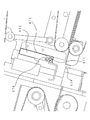
次に、図2を用いてシート断裁装置としてのトリマーユニット600について説明する。トリマーユニット600には、シート束の搬送方向上流側(以下、単に上流側という)から順番に、第1搬送部610、第2搬送部620、トリム部630、第3搬送部640、第4搬送部650、排出部660が配置されている。
(Trimmer unit)
Next, a
第1搬送部610は、中綴じ製本部800からシート束を受け取るために下側のみに下搬送ベルト611を持ち、また、下搬送ベルトの両側にサイドガイド612が配設され、これらがシート束の幅方向に動作することで、シートの斜行を修正することができる。また、サイドガイド612にはシート束の開きを防止する押さえガイド614が配設されており、第2搬送部620にスムーズにシート束の受け渡しをできるようになっている。
The
押さえガイド614の上流側及び下流側にはシート束の有無を検知する第1搬送部入口センサ615、第1搬送部出口センサ616が配設されている。下搬送ベルト611の両側には搬送爪613が配設されている。搬送爪613はシート束搬送方向に移動が可能であり、第2搬送部に受け渡すために下搬送ベルト611と同じ速度で移動する。下搬送ベルト611とシート束との間にすべりが生じた場合は、搬送爪613がシート束後端と接触し、搬送できなくならないようシート束後端を押しながら搬送する。
A first conveyance unit inlet sensor 615 and a first conveyance unit outlet sensor 616 that detect the presence or absence of a sheet bundle are disposed on the upstream side and the downstream side of the
次に、第2、第3、第4搬送部は一対の搬送ベルト621,622及び645,646及び655,656を有し、各搬送部の上下の搬送ベルトは、同一のモータによって駆動され、同一の搬送速度となるよう構成されている。
Next, the second, third, and fourth transport units have a pair of
第2搬送部620の挟持部Jの下流には第2搬送部入口センサ623が配設され、第2搬送部にシート束が受け渡されたことを検知するようになっている。第3搬送部640には、出没可能で、搬送方向にも移動可能なストッパ641が配設されている。ストッパ641はK部を回動中心としてカム642,648を介し、モータによって駆動され、出現、退避が可能である。また、ストッパ641はスライドブロック643に搭載され、スライドガイド644に沿ってモータ(不図示)により駆動され、シート束の搬送方向サイズやシート束の停止位置に応じて移動する。第4搬送部650はシート束を上方に搬送する。
A second conveyance
トリム部630には、カッターユニット631が搬送経路と直交方向に配置されている。図4はトリム部の拡大図である。図6はトリム部周辺の斜視図であり、説明のため、第3搬送部付近のみの部品を示し、また、上側の搬送ベルト等を省略してある。図5は図4の矢印A方向から見た図であり、断裁刃の部分を示している。
A
カッターユニット631はモータ(不図示)によって駆動され、リンク637(図6に示すリンク637a,637b)によって搬送面に対して垂直方向に上下動する。押さえ部材632、上刃(可動刃)633はカッターユニット631中に配置され、カッターユニット631が下方に移動する際、先行して押さえ部材632がシート束に当接する。押さえ部材632は、バネ(不図示)によって下方向に付勢されているため、シート束を搬送面との間に挟持する。この状態で、さらにカッターユニット631が下方に移動し、上刃633と上刃633の移動方向下流側に固定された下刃(固定刃)634によって、シート束を断裁することができる。この際、カッターユニット631に取り付けられ搬送パス外に設けられたカム636によって、第2搬送部の下流側に配設されたシャッター625が押され、支点Qを中心としてカッターユニット631の下降に合わせて開閉する。また、カッターユニット631の下方(上刃633の移動方向の延長位置)には、収容箱635が配置され、カッターユニット631によって断裁されたシートの断裁片を収容する。シャッター625はカム636で押されていないときは、ねじりコイルバネ(不図示)によって付勢され、搬送ベルト622から下刃634を繋ぐ搬送ガイドとなり、収容箱635への断裁片の通過経路を閉鎖している。最下流に排出部660が配置され、第4搬送部650によって搬送されてくるシート束を積載する。
The
図7は上刃633付近の拡大図である。この図7にも示すように、上刃633は可動刃であり、シート(ここではシート束)を断裁するための鋭角な刃先を形成するテーパ面670を有している。672は押し部材であり、上刃633とともに下降して上刃633が断裁したシート束の断裁片を上刃633から引き離す方向に押すように、上刃633に固定されている。押し部材672には、上刃633の刃先を形成するテーパ面670が上刃633の移動方向を基準にしてなす角度αより大きな角度βをなす押し面671が設けられている。この押し面671は、上刃633の先端より移動方向上流側に位置し、その端部が上刃633のテーパ面670に一体的に設けられ、密着している。上刃633の刃先と押し面671は長手方向に略平行(図5参照)に、かつ押し面671は上刃633の先端から所定量引っ込んだ位置になるように配置されている。ここでは押し面671は、カッターユニット631の移動方向と略直角な面を成しており、断裁動作に連動して上刃633と共に下降をして、断裁されたシートの断裁片を押し下げる。押し面671が断裁片を押し下げる効果は、押し面671が上刃633の先端に近いほど高いため、押し面671は断裁を阻害しない程度に上刃633の先端に近づけられている。
FIG. 7 is an enlarged view of the vicinity of the
上刃633の刃先は、図5に示すように装置奥側から手前にかけて上昇する直線状であり、下刃634は搬送経路と水平な形状をしている。したがって上刃633は下降すると、点接触で下刃634上のシート束に突き当たり、シート束を奥側から手前側にかけて連続的に順次切断していく。また下刃634は上刃633とともにシート束を断裁する固定刃であり、可動刃である上刃633は押し面671が下刃634の先端を越えて下降するようになっている。
The cutting edge of the
また、図5及び図6に示すように押し面671は、上刃633の移動方向と交差する長手方向において、上刃633の先端に沿って間隔をあけて複数設けられている。具体的には、押し面671は、上刃633の長手方向で櫛歯状に複数(ここでは6箇所)に分割されている。ここでは各押し面671の幅(長手方向の長さ)は約10mmに設定されている。これにより、上刃633とシートの断裁片との接触面積を、分割されない形状に比べて極めて小さくすることができ、静電気による断裁片の貼り付きを発生しにくくすることができる。
As shown in FIGS. 5 and 6, a plurality of
さらに、押し面671を有する押し部材672は、導電性を有する材料(例えばステンレス)で構成されており、電気的に接地されている。さらにここでは、押し部材672だけでなく、上刃633、下刃634も、枠体を通して電気的に接地されている。このため、静電気による断裁片の貼り付きをさらに発生にくくすることができ、静電気により断裁片の落下が阻害されることはない。
Further, the pressing
また押し面671は、トリム部630に搬送される各種サイズのシート束Tに対応しており、どのようなサイズのシート束であっても、その断裁片を確実に押し下げることができる。
Further, the
そして、押し部材672は、弾性特性を有していて、押し面671の先端は前述したように上刃633のテーパ面670にそれぞれが密着している。こうすることで、押し面671と上刃633の隙間を確実に無くし、断裁動作でシートの断裁片が両者の間に入り込むのを防止することができる。
The pressing
(制御系)
図8は、複写機1000のブロック図である。CPU回路部150は、CPU(不図示)を有する。そして、ROM151に格納された制御プログラム及び操作部1の設定に従い、原稿給送制御部101、イメージリーダ制御部201、画像信号制御部202、プリンタ制御部301、折り処理制御部401、フィニッシャ制御部501、外部I/F203を制御する。そして、原稿給送制御部101は原稿給送部100を、イメージリーダ制御部201はイメージリーダ部200を、プリンタ制御部301はプリンタ部300を、折り処理制御部401は折り処理部400を各々制御する。また、フィニッシャ制御部501はフィニッシャ500、トリマーユニット600、中綴じ製本部800、インサータ900を制御する。
(Control system)
FIG. 8 is a block diagram of the copying
操作部1は、画像形成に関する各種機能を設定するための複数のキー、設定状態を表示するための表示部等を有する。そして、ユーザによる各キーの操作に対応するキー信号をCPU回路部150に出力すると共に、CPU回路部150からの信号に基づき対応する情報を表示部に表示する。
The
RAM152は、制御データを一時的に保持するための領域や、制御に伴う演算の作業領域として用いられる。外部I/F203は、複写機1000と外部のコンピュータ204とのインタフェースであり、コンピュータ204からのプリントデータをビットマップ画像に展開し、画像データとして画像信号制御部202へ出力する。また、イメージリーダ制御部201から画像信号制御部202へは、イメージセンサ(不図示)で読み取った原稿の画像が出力される。プリンタ制御部301は、画像信号制御部202からの画像データを露光制御部(不図示)へ出力する。
The
(シート束断裁動作)
次に、上記構成に基づき、トリマーユニット600におけるシート束の流れと共に各部の動作を説明する。
(Sheet cutting operation)
Next, based on the above configuration, the operation of each unit will be described together with the flow of the sheet bundle in the
折り目プレスユニット860で折り強化されたシート束は、搬送が再開され、トリマーユニット600の第1搬送部610へ受け渡される。第1搬送部610の下搬送ベルト611が回転し、シート束を搬送し、第1搬送部出口センサ616でシート束を検知した後、搬送を一旦停止する。その後、搬送経路の両側に配設されたサイドガイド612が整合動作を行う。その後、第1搬送部の上流に配置された搬送爪613と下搬送ベルト611によって、シート束の搬送が再開される。そして、第2搬送部620の挟持部Jに配設された第2搬送部入口センサ623でシート束を検知すると搬送爪613は搬送上流に退避する。そして、シート束は、第2搬送部620、トリム部630を通過し、第3搬送部640へと搬送される。第3搬送部640では、搬送されるシート束のサイズに合わせて適切な位置にストッパ641があらかじめ搬送経路上に出現しており、シート束はストッパ641に当接して所定の位置で停止する(図6、図9参照)。その後、第3搬送部640の搬送ベルトが停止し、トリム部630のカッターユニット631が下降を開始して、上刃633はシート束後端を切断加工していく。
The sheet bundle reinforced by the
このとき上刃633は刃先の形状にしたがって、奥側から順次シート束を断裁する。断裁片Gは、上刃633と共に下降する押し面671に引っかかり、外的抵抗(静電気、空気抵抗、摺動抵抗)に打ち勝つ力で、強制的に押し下げられる(図10、図11参照)。押し面671は、前述したように断裁片Gと接触するが、その接触面積は小さく、かつ導電性部材で作られているので、静電気等の影響を受けて断裁片Gの落下が阻害されることもない。上刃633の可動領域最下点付近である下死点Dにおいて、押し面671は下刃634より下降に位置しており、上刃633の下死点Dへの移動により断裁片Gは、確実に刃面から分離して下方に落下していく。
At this time, the
上刃633に接続されたカム636で押されることで、シャッター625はシート束切断前には切断部から収容箱635までの断裁片の通過経路を開放している。カッターユニット631はリンク637の可動領域最下点付近である下死点D付近で一旦停止した後、初期位置(リンク637の可動領域最上点付近である上死点U)まで復帰する。カッターユニット631の下死点Dでの停止時間は中綴じ製本部800で作成されるシート束の最小束内枚数における束間時間で間に合うように設定している。カッターユニット631が下死点Dにおいて停止することにより、シャッター625の断裁片の通過経路開放時間が確保され、上述したように落下する断裁片Gが確実に収容箱635に落下する。また、カッターユニット631が初期位置(上死点U)に復帰するに伴い、カム636がシャッター625から離れ、ねじりコイルバネ(不図示)によりシャッター625が断裁片の通過経路を閉鎖する。その後、前述のストッパ641は退避し、第3搬送部640の搬送が再開される。シート束は、第3搬送部640の下流に配設されている、第4搬送部650へ受け渡される。
By being pushed by a
第4搬送部650によって上方に搬送されたシート束は排出部660へ排出され、順次かわら状に積み重ねられていく。第4搬送部650によって排出口を上部に配設することにより、ユーザのシート束の取り出し性が向上されている。
The sheet bundle transported upward by the
続いてシート束が搬送される場合は、同様の動作が繰り返されて、所望の部数が排出部660に積載される。
Subsequently, when the sheet bundle is conveyed, the same operation is repeated and a desired number of copies are stacked on the
上述したように、本実施形態によれば、上刃633とともに下降する押し部材672の押し面671でシートの断裁片Gを強制的に押し下げる。このため、シートの断裁片Gを、搬送経路に残すことなく、確実に落下させることができ、収容箱635に収容することができる。
As described above, according to the present embodiment, the cut piece G of the sheet is forcibly pushed down by the pushing
また、押し部材672の押し面671の移動は、上刃633に連動するものであるから、新たに駆動機構を設ける必要がなく、簡易な構成で実現ができる。
Further, since the movement of the
シートの断裁片Gを、搬送経路に残すことなく、確実に落下させることができるので、断裁片がシートとともに積載収容されることによる品位の低下や、搬送経路内のセンサの誤動作を防止することができ、信頼性の高い動作が実現できる。 Since the cut piece G of the sheet can be reliably dropped without leaving it in the conveyance path, it is possible to prevent degradation of the quality due to the cut pieces being stacked and accommodated together with the sheet and malfunction of the sensor in the conveyance path. And a highly reliable operation can be realized.
〔他の実施形態〕
前述した実施形態では、断裁片の貼り付きを防止して、落下性を向上させるために、断裁片との接触面積を小さくする構成として、上刃633に対し、櫛歯状に分割された押し面671を有する押し部材672を取り付けた構成を例示した。しかしながら、本発明はこれに限定されるものではない。
[Other Embodiments]
In the above-described embodiment, in order to prevent sticking of the cutting piece and to improve the dropability, the
同様の効果を得るために、シートに対して移動をしてシートを断裁する可動刃の先端に沿って、その先端から所定量引っ込ませて段差形状を形成するようにしても良い。具体的には、例えば、図12及び図13に示すように、可動刃である上刃633の、先端を除いた上方に、櫛歯状の凹凸形状(複数の溝675)を直接設けても良い。その他の構成は前述した実施形態と同様である。
In order to obtain the same effect, a step shape may be formed by retracting a predetermined amount from the tip of the movable blade that moves relative to the sheet and cuts the sheet. Specifically, for example, as shown in FIGS. 12 and 13, a comb-like uneven shape (a plurality of grooves 675) may be provided directly above the
この上刃633による断裁では、断裁後のシートの断裁片Gは上刃633の凸部のみと接触する為、貼り付きを引起すことなく、落下することができる。
In the cutting with the
また、可動刃である上刃に対し、溝の代わりに、穴を設けることにより、断裁片との接触面積を小さくさせても良い。このように、押し部材の押し面の代わりに、刃面の一部を、断裁片との接触面積を小さくする形状にすることにより、断裁片の静電吸着を防止できる。 Moreover, you may make a contact area with a cutting piece small by providing a hole instead of a groove | channel with respect to the upper blade which is a movable blade. Thus, instead of the pressing surface of the pressing member, a portion of the blade surface is shaped to reduce the contact area with the cutting piece, thereby preventing electrostatic attraction of the cutting piece.
また前述した実施形態の押し面671は、カッターユニット631の移動方向と略直角な面を形成していたが、本発明はこれに限定されるものではない。押し面671は、上刃633の下降方向に対してテーパ面670がなす角度αより大きな角度βをなすものであれば、その他の形状であっても良い。例えば、図14に示すように、押し面671をR形状にしても良い。或いは、図15に示すように、押し面671を、直角より大きい角度βをなすテーパ形状(図15(a)参照)、直角より小さい角度βをなすテーパ形状(図15(b)参照)にしてもかまわない。この場合、断裁片Gと押し面671とは同一面ではないため、押し下げ力の伝達効率は減少するが、両者の接触面積は更に小さくなり、貼り付きにくくなる。
Moreover, although the
さらに前述した実施形態では、押し面を有する押し部材を可動刃に取り付けた構成を例示したが、これに限定されるものではない。押し面の形状を可動刃に直接成形するなど、押し面を有する押し部材と可動刃を同一の部材で一体成形した構成としても良い。この構成により、部品を減らしながらシートの断裁片の落下性を向上させることができる。 Further, in the above-described embodiment, the configuration in which the pressing member having the pressing surface is attached to the movable blade is exemplified, but the present invention is not limited to this. A configuration in which the pressing member having the pressing surface and the movable blade are integrally formed of the same member, for example, the shape of the pressing surface is directly formed on the movable blade. With this configuration, it is possible to improve the dropability of the cut piece of the sheet while reducing the number of parts.
なお前述した実施形態では、画像形成装置として複写機を例示したが、本発明はこれに限定されるものではない。例えばプリンタ、ファクシミリ装置等の他の画像形成装置や、或いはこれらの機能を組み合わせた複合機等の他の画像形成装置であっても良い。これらの画像形成装置に用いられるシート断裁装置に本発明を適用することにより同様の効果を得ることができる。 In the above-described embodiment, a copying machine is exemplified as the image forming apparatus, but the present invention is not limited to this. For example, the image forming apparatus may be another image forming apparatus such as a printer or a facsimile apparatus, or another image forming apparatus such as a multi-function machine that combines these functions. The same effect can be obtained by applying the present invention to a sheet cutting apparatus used in these image forming apparatuses.
また前述した実施形態では、画像形成装置に対して着脱自在なシート断裁装置を例示したが、本発明はこれに限定されるものではない。例えば画像形成装置が一体に有するシート断裁装置であっても良く、該シート断裁装置に本発明を適用することにより同様の効果を得ることができる。 In the above-described embodiment, the sheet cutting apparatus that is detachable from the image forming apparatus is exemplified, but the present invention is not limited to this. For example, the image forming apparatus may be a sheet cutting apparatus that is integrally provided, and the same effect can be obtained by applying the present invention to the sheet cutting apparatus.
G …断裁片
S …ステイプル針
T …シート束
600 …トリマーユニット
610 …第1搬送部
611 …下搬送ベルト
612 …サイドガイド
613 …搬送爪
614 …押さえガイド
615 …第1搬送部入口センサ
616 …第1搬送部出口センサ
620 …第2搬送部
621,622,645,646,655,656 …搬送ベルト
623 …第2搬送部入口センサ
630 …トリム部
631 …カッターユニット
632 …押さえ部材
633 …上刃
634 …下刃
635 …収容箱
636 …カム
640 …第3搬送部
641 …ストッパ
650 …第4搬送部
660 …排出部
670 …テーパ面
671 …押し面
672 …押し部材
1000 …複写機
G ... Cutting piece S ... Staple needle T ...
Claims (9)
前記可動刃の断裁時の移動方向において前記可動刃の先端より上流側に所定距離引っ込んだ位置に設けられ、前記可動刃とともに前記シート積載面を越えて下方に移動して前記可動刃が断裁したシートの断裁片を押すための押し面を有する押し部材と、
を備え、
前記可動刃は、前記可動刃の断裁時の移動方向を基準として鋭角をなし、シートを断裁するための刃先を形成するテーパ面を有し、
前記押し部材は、前記可動刃のテーパ面に一体的に設けられ、前記押し部材の前記押し面と前記可動刃の前記テーパ面がなす角度が鈍角であることを特徴とするシート断裁装置。 And a movable blade which moves downward past the sheet stacking surface of the sheet are stacked to cut the sheets stacked on said sheet stacking surface,
Provided at a position retracted a predetermined distance upstream from the tip of the movable blade in the moving direction when cutting the movable blade, and moved downward together with the movable blade over the sheet stacking surface and cut the movable blade A pressing member having a pressing surface for pressing the cut piece of the sheet;
With
The movable blade has an acute angle with respect to the moving direction at the time of cutting the movable blade, and has a tapered surface that forms a cutting edge for cutting the sheet,
The sheet cutting device , wherein the pressing member is integrally provided on a tapered surface of the movable blade, and an angle formed by the pressing surface of the pressing member and the tapered surface of the movable blade is an obtuse angle .
前記可動刃は、前記可動刃の断裁時の移動方向を基準として鋭角をなし、シートを断裁するための刃先を形成するテーパ面を有し、
前記可動刃のテーパ面の、前記可動刃の断裁時の移動方向において前記可動刃の先端から所定距離引っ込んだ位置に、前記可動刃のテーパ面と鈍角をなす段差が形成されることを特徴とするシート断裁装置。 A movable blade that cuts down the sheets stacked on the sheet stacking surface by moving downward beyond the sheet stacking surface on which the sheets are stacked ;
The movable blade has an acute angle with respect to the moving direction at the time of cutting the movable blade, and has a tapered surface that forms a cutting edge for cutting the sheet,
A step that forms an obtuse angle with the tapered surface of the movable blade is formed at a position where the tapered surface of the movable blade is retracted a predetermined distance from the tip of the movable blade in the moving direction when cutting the movable blade. Sheet cutting device.
Priority Applications (2)
| Application Number | Priority Date | Filing Date | Title |
|---|---|---|---|
| JP2008028621A JP5305679B2 (en) | 2007-02-27 | 2008-02-08 | Sheet cutting apparatus and image forming apparatus |
| US12/034,187 US8616106B2 (en) | 2007-02-27 | 2008-02-20 | Sheet cutting apparatus and image forming apparatus |
Applications Claiming Priority (3)
| Application Number | Priority Date | Filing Date | Title |
|---|---|---|---|
| JP2007046860 | 2007-02-27 | ||
| JP2007046860 | 2007-02-27 | ||
| JP2008028621A JP5305679B2 (en) | 2007-02-27 | 2008-02-08 | Sheet cutting apparatus and image forming apparatus |
Publications (3)
| Publication Number | Publication Date |
|---|---|
| JP2008238394A JP2008238394A (en) | 2008-10-09 |
| JP2008238394A5 JP2008238394A5 (en) | 2011-05-06 |
| JP5305679B2 true JP5305679B2 (en) | 2013-10-02 |
Family
ID=39910326
Family Applications (1)
| Application Number | Title | Priority Date | Filing Date |
|---|---|---|---|
| JP2008028621A Active JP5305679B2 (en) | 2007-02-27 | 2008-02-08 | Sheet cutting apparatus and image forming apparatus |
Country Status (1)
| Country | Link |
|---|---|
| JP (1) | JP5305679B2 (en) |
Families Citing this family (4)
| Publication number | Priority date | Publication date | Assignee | Title |
|---|---|---|---|---|
| JP2010284766A (en) * | 2009-06-15 | 2010-12-24 | Tsubouchi Masako | Paper cutting device |
| JP5448609B2 (en) | 2009-06-30 | 2014-03-19 | キヤノン株式会社 | Cutting apparatus and image forming apparatus |
| JP5264971B2 (en) | 2010-10-14 | 2013-08-14 | キヤノン株式会社 | Sheet processing apparatus and image forming apparatus |
| JP6283178B2 (en) * | 2013-07-22 | 2018-02-21 | キヤノンファインテックニスカ株式会社 | Sheet cutting device |
Family Cites Families (6)
| Publication number | Priority date | Publication date | Assignee | Title |
|---|---|---|---|---|
| JPH0437759Y2 (en) * | 1986-02-14 | 1992-09-04 | ||
| JP2726397B2 (en) * | 1995-01-13 | 1998-03-11 | 東北リコー株式会社 | Cutter equipment |
| JPH09262789A (en) * | 1996-03-27 | 1997-10-07 | Totani Giken Kogyo Kk | Plastic film cutter |
| JP3849334B2 (en) * | 1999-01-08 | 2006-11-22 | コニカミノルタホールディングス株式会社 | Sheet cutting method, sheet cutting apparatus, sheet post-processing apparatus, and image forming apparatus |
| ATE492379T1 (en) * | 2006-04-04 | 2011-01-15 | Mueller Martini Holding Ag | CUTTING DEVICE WITH A CHIP DISCHARGE DEVICE SUPPLYING BLOW AIR |
| JP2007307656A (en) * | 2006-05-18 | 2007-11-29 | Konica Minolta Business Technologies Inc | Cutting device, post-treatment device and image formation device |
-
2008
- 2008-02-08 JP JP2008028621A patent/JP5305679B2/en active Active
Also Published As
| Publication number | Publication date |
|---|---|
| JP2008238394A (en) | 2008-10-09 |
Similar Documents
| Publication | Publication Date | Title |
|---|---|---|
| JP5264971B2 (en) | Sheet processing apparatus and image forming apparatus | |
| US7954798B2 (en) | Sheet finishing apparatus and control method | |
| JP5284060B2 (en) | Sheet processing apparatus and image forming apparatus | |
| US8616106B2 (en) | Sheet cutting apparatus and image forming apparatus | |
| US8702086B2 (en) | Sheet post-processing apparatus and image forming apparatus | |
| JP2010036333A (en) | Sheet processing device and image forming device | |
| JP5448609B2 (en) | Cutting apparatus and image forming apparatus | |
| JP2010189190A (en) | Sheet post-processing device, and image forming apparatus with the same | |
| JP5305679B2 (en) | Sheet cutting apparatus and image forming apparatus | |
| JP4861215B2 (en) | Sheet processing apparatus and image forming apparatus | |
| US9897962B2 (en) | Sheet processing device and image forming apparatus provided with the same | |
| JP4921192B2 (en) | Sheet cutting apparatus and image forming apparatus | |
| JP4986825B2 (en) | Sheet processing apparatus and image forming apparatus | |
| JP5562447B2 (en) | Sheet processing apparatus and image forming apparatus | |
| JP4795261B2 (en) | Sheet post-processing apparatus and image forming apparatus | |
| JP2013071189A (en) | Sheet punching device, sheet processing device, and image forming device | |
| JP5312066B2 (en) | Sheet processing apparatus and image forming apparatus | |
| JP2007045621A (en) | Sheet processor | |
| JP2010120705A (en) | Sheet stacking device and image forming device | |
| JP2007131436A (en) | Sheet handling device and image forming device equipped with it |
Legal Events
| Date | Code | Title | Description |
|---|---|---|---|
| A521 | Written amendment |
Free format text: JAPANESE INTERMEDIATE CODE: A523 Effective date: 20110201 |
|
| A621 | Written request for application examination |
Free format text: JAPANESE INTERMEDIATE CODE: A621 Effective date: 20110201 |
|
| A521 | Written amendment |
Free format text: JAPANESE INTERMEDIATE CODE: A523 Effective date: 20110322 |
|
| A131 | Notification of reasons for refusal |
Free format text: JAPANESE INTERMEDIATE CODE: A131 Effective date: 20121023 |
|
| A977 | Report on retrieval |
Free format text: JAPANESE INTERMEDIATE CODE: A971007 Effective date: 20121025 |
|
| A521 | Written amendment |
Free format text: JAPANESE INTERMEDIATE CODE: A523 Effective date: 20121218 |
|
| TRDD | Decision of grant or rejection written | ||
| A01 | Written decision to grant a patent or to grant a registration (utility model) |
Free format text: JAPANESE INTERMEDIATE CODE: A01 Effective date: 20130528 |
|
| A61 | First payment of annual fees (during grant procedure) |
Free format text: JAPANESE INTERMEDIATE CODE: A61 Effective date: 20130625 |
|
| R151 | Written notification of patent or utility model registration |
Ref document number: 5305679 Country of ref document: JP Free format text: JAPANESE INTERMEDIATE CODE: R151 |