JP5304332B2 - Image forming apparatus and image forming method - Google Patents
Image forming apparatus and image forming method Download PDFInfo
- Publication number
- JP5304332B2 JP5304332B2 JP2009053486A JP2009053486A JP5304332B2 JP 5304332 B2 JP5304332 B2 JP 5304332B2 JP 2009053486 A JP2009053486 A JP 2009053486A JP 2009053486 A JP2009053486 A JP 2009053486A JP 5304332 B2 JP5304332 B2 JP 5304332B2
- Authority
- JP
- Japan
- Prior art keywords
- process control
- image forming
- power
- forming apparatus
- unit
- Prior art date
- Legal status (The legal status is an assumption and is not a legal conclusion. Google has not performed a legal analysis and makes no representation as to the accuracy of the status listed.)
- Expired - Fee Related
Links
Images


Description
本発明は、充放電が可能な蓄電手段を備えた画像形成装置、および、画像形成装置による画像形成方法に関する。 The present invention relates to an image forming apparatus including a power storage unit capable of charging and discharging, and an image forming method using the image forming apparatus.
従来、画像形成装置としては、複写機、プリンタ、ファクシミリおよびそれらの機能を複合化した装置等が開発されている。このような画像形成装置は、通常、記録媒体上にトナー画像を形成する画像形成部、トナー画像が形成された記録媒体を加圧および加熱してトナー画像の定着を行う定着装置部を備えている。この定着装置部には、記録媒体を加熱するための定着部材、例えば定着ローラが設けられており、この定着ローラは、商用電源からの電力により発熱するヒータ(加熱ヒータ)によって所定の温度に加熱される。 Conventionally, as an image forming apparatus, a copying machine, a printer, a facsimile, and an apparatus that combines these functions have been developed. Such an image forming apparatus usually includes an image forming unit for forming a toner image on a recording medium, and a fixing device unit for fixing the toner image by pressurizing and heating the recording medium on which the toner image is formed. Yes. The fixing device section is provided with a fixing member, for example, a fixing roller, for heating the recording medium. The fixing roller is heated to a predetermined temperature by a heater (heater heater) that generates heat by electric power from a commercial power source. Is done.
また、画像形成装置には、転写画質維持を図るために、プロセスコントロール(プロコン)と呼ばれる画質調整モードが設けられ、形成する画像の画質を最適化するべく作像条件を調整している。画像形成装置は、電源投入後、CPU初期化、周辺デバイスの初期設定を経て、定着温度をプリントが可能な温度に立ち上げる定着リロード、プロコンを経てプリント動作が可能となる。 Further, in order to maintain the transfer image quality, the image forming apparatus is provided with an image quality adjustment mode called process control (process control), and the image forming conditions are adjusted to optimize the image quality of the image to be formed. After the power is turned on, the image forming apparatus can perform a printing operation through a CPU initialization and peripheral device initial settings, a fixing reload for raising the fixing temperature to a temperature at which printing can be performed, and a computer control.
長時間における画像形成部の放置後プロコンを行わずにプリントを行うと、画像品質の低下を引き起こしてしまう問題があるため、従来の画像形成装置では、立上げの電源投入時にはプロコンを行っている。プロコン動作の所要時間は、通常10数秒〜数10秒程度が必要であり、プロコン動作の所要電力は、カラータンデム機等では通常数百W程度が必要である。そのため、画像形成装置の立上げ時(電源投入時)にプロコンを行うと、プロコンの所要時間分だけ、プリント動作が可能になるまでの時間が長くなるという問題がある。また、プロコンと定着リロードとを並行して実施した場合でも、プロコンの所要電力分だけ、定着装置での定着リロードに必要な電力供給量を減らす必要があるため、定着温度がプリント可能な温度に立ち上がるまでの時間が長くなり、プリント動作が可能になるまでの時間が長くなる。 If printing is performed without leaving the image forming unit after leaving the image forming unit for a long time, there is a problem that the image quality is deteriorated. Therefore, in the conventional image forming apparatus, the image forming unit is turned on when the power is turned on. . The time required for the process control operation is normally about 10 to several tens of seconds, and the power required for the process control operation is usually about several hundred W in a color tandem machine or the like. Therefore, if the process control is performed when the image forming apparatus is started up (when the power is turned on), there is a problem that the time required for the printing operation becomes longer by the time required for the process control. In addition, even when the control unit and fixing reload are executed in parallel, it is necessary to reduce the amount of power supply required for fixing reload in the fixing device by the amount of power required by the control unit. It takes longer time to stand up and a longer time until printing operation becomes possible.
この問題に対して、特許文献1には、電源投入後にプリント動作が可能になるまでの時間短縮を図るために画像形成部の動作OFF時間に閾値を設け、閾値より画像形成部の動作OFF時間が長い場合のみ電源投入時にプロコンを実施する画像形成装置が開示されている。この画像形成装置では、画像形成部の動作終了からの時間をカウントしており、電源投入時に、予め決めている画像形成部の動作OFF時間の閾値を超えているか否かを検出して、プロコン実行可否を決定している。このため、環境条件によっては、電源投入時にプロコンを行う必要がなく、プリント動作が可能になるまでの時間を短縮することが可能である。 With respect to this problem, Japanese Patent Application Laid-Open No. H10-228561 provides a threshold value for the operation OFF time of the image forming unit in order to shorten the time until the printing operation can be performed after the power is turned on. Discloses an image forming apparatus that executes the process control when the power is turned on only when the time is long. In this image forming apparatus, the time from the end of the operation of the image forming unit is counted. When the power is turned on, it is detected whether or not a predetermined threshold value for the operation OFF time of the image forming unit is exceeded, and Whether to execute is determined. Therefore, depending on the environmental conditions, it is not necessary to perform a process control when the power is turned on, and it is possible to shorten the time until the printing operation becomes possible.
しかしながら、特許文献1では、画像形成部の動作OFF時間の閾値設定は、数時間に設定されている。そのため、朝1番の電源投入時には、ほとんどの場合プロコンを実施することになり、プリント動作が可能になるまでの時間を短縮することができないという問題があった。 However, in Patent Document 1, the threshold setting for the operation OFF time of the image forming unit is set to several hours. For this reason, when the power is turned on in the morning, the computer control is almost always executed, and there is a problem that the time until the printing operation can be performed cannot be shortened.
一方、画像形成部の動作OFF時間の閾値設定を長くすれば、朝1番の電源投入時にプロコンを実施する割合が少なくなり、プリント動作が可能になるまでの時間を短縮することが可能である。しかし、その代わりに画像品質が低下するという問題が発生する可能性があり、一般的には画像形成部の動作OFF時間の閾値は数時間程度にしか設定できない。 On the other hand, if the threshold setting for the operation OFF time of the image forming unit is lengthened, the ratio of executing the computer control at the first power-on in the morning decreases, and the time until the printing operation becomes possible can be shortened. . However, there is a possibility that the image quality deteriorates instead. Generally, the threshold value of the operation OFF time of the image forming unit can be set to only about several hours.
本発明は、上記に鑑みてなされたものであって、朝1番などの電源がOFFになってから長時間経過した後の電源投入時であっても、プロセスコントロールを実施することなく短時間でプリント動作を可能とすることができる画像形成装置および画像形成方法を提供することを目的とする。 The present invention has been made in view of the above, and even when the power is turned on after a long time has passed since the power supply of No. 1 in the morning is turned off, the process control is not performed for a short time. An object of the present invention is to provide an image forming apparatus and an image forming method capable of performing a printing operation.
上述した課題を解決し、目的を達成するために、本発明は、電源からの電力供給の有無を検知する検知手段と、画像形成動作終了後の経過時間を測定する測定手段と、充放電が可能な蓄電手段と、形成する画像の画質を調整するプロセスコントロールの実行を制御するプロセスコントロール制御手段と、前記検知手段および前記測定手段の状態を監視し、前記電力供給が無いと判断し、かつ、前記画像形成動作終了後の経過時間が所定の時間を越えたと判断した場合、前記蓄電手段の蓄電力を前記プロセスコントロール制御手段へ出力させるプロセスコントロール要因監視手段と、を備え、前記蓄電手段は、前記プロセスコントロール要因監視手段へ前記蓄電力を出力すること、を特徴とする。 In order to solve the above-described problems and achieve the object, the present invention includes a detection unit that detects the presence or absence of power supply from a power source, a measurement unit that measures an elapsed time after the end of an image forming operation, and charge / discharge. Monitoring the status of the possible power storage means, process control control means for controlling the execution of process control for adjusting the image quality of the image to be formed, the detecting means and the measuring means, and determining that there is no power supply; and And a process control factor monitoring means for outputting the stored power of the power storage means to the process control control means when it is determined that the elapsed time after the completion of the image forming operation exceeds a predetermined time, the power storage means The stored power is output to the process control factor monitoring means .
また、本発明は、画像形成装置で実行される画像形成方法であって、電源からの電力供給の有無を検知する検知ステップと、画像形成動作終了後の経過時間を測定する測定ステップと、蓄電手段に充電を行う蓄電ステップと、形成する画像の画質を調整するプロセスコントロールの実行を制御するプロセスコントロール制御ステップと、前記蓄電手段から蓄電力が供給されるプロセスコントロール要因監視手段が、前記検知ステップで前記電力供給が無いと判断し、かつ、前記測定ステップで前記経過時間が所定の時間を越えたと判断した場合、前記蓄電手段の蓄電力を前記プロセスコントロール制御ステップで使用させる蓄電力使用ステップと、を含むこと、を特徴とする。 Further, the present invention provides an image forming method executed in the image forming apparatus, a detection step for detecting the presence or absence of power supply from the power source, a measuring step of measuring an elapsed time after the image forming operation is completed, the power storage A storage step for charging the means ; a process control control step for controlling execution of a process control for adjusting the image quality of the image to be formed; and a process control factor monitoring means for supplying stored power from the storage means. And when the measurement step determines that the elapsed time has exceeded a predetermined time, the stored power use step for using the stored power of the power storage means in the process control control step. , Including.
本発明によれば、プロセスコントロール要因監視手段が、電源からの電力供給が無いと判断し、かつ、画像形成動作終了後の経過時間が所定の時間を越えたと判断した場合、蓄電手段の蓄電力をプロセスコントロール制御手段へ出力させることができるので、電源のOFF中に蓄電手段の蓄電力を用いてプロセスコントロールを行うことができ、長期間電源入力がOFFであった状態から朝1番などに電源入力をONする場合でもプロセスコントロールを行う必要がないので、プリント動作が可能となるまでの時間を短縮することができるという効果を奏する。 According to the present invention, when the process control factor monitoring unit determines that there is no power supply from the power source and determines that the elapsed time after the end of the image forming operation has exceeded a predetermined time, the stored power of the power storage unit Can be output to the process control control means, so that the process control can be performed by using the stored power of the power storage means while the power is off, and the power input is turned off for a long time, etc. Since it is not necessary to perform process control even when the power input is turned on, there is an effect that it is possible to shorten the time until the printing operation becomes possible.
以下に添付図面を参照して、この発明にかかる画像形成装置および画像形成方法の最良な実施の形態を詳細に説明する。 Exemplary embodiments of an image forming apparatus and an image forming method according to the present invention are explained in detail below with reference to the accompanying drawings.
図1は、本実施の形態にかかる画像形成装置の電力供給を示す機能図である。初めに、商用交流電力が供給された後、画像形成装置で必要な直流電圧に変換される部分と、その直流電圧が供給される部分とについて説明する。 FIG. 1 is a functional diagram showing power supply of the image forming apparatus according to the present embodiment. First, a part that is converted into a DC voltage required by the image forming apparatus after commercial AC power is supplied and a part to which the DC voltage is supplied will be described.
ACスイッチ1は、商用交流電源2と画像形成装置とを接続するスイッチである。ACスイッチ1がOFFの時、RTC13とプロコン要因監視部14以外の回路には、電力が供給されないため、その機能が停止している状態となる。
The AC switch 1 is a switch that connects the commercial AC power supply 2 and the image forming apparatus. When the AC switch 1 is OFF, power is not supplied to circuits other than the
電圧検知回路3は、商用交流電源2からの電力(電圧)の入力を検知するため、ACスイッチ1の後段に設けられる。電圧検知回路3は、ACスイッチ1がONしている場合は、商用交流電源2からの電圧を検知するが、ACスイッチ1がOFFしている場合は、商用交流電源2からの電圧を検知しない。なお、電圧検知回路3は、請求項における検知手段に相当する。 The voltage detection circuit 3 is provided in the subsequent stage of the AC switch 1 in order to detect the input of power (voltage) from the commercial AC power supply 2. The voltage detection circuit 3 detects the voltage from the commercial AC power supply 2 when the AC switch 1 is ON, but does not detect the voltage from the commercial AC power supply 2 when the AC switch 1 is OFF. . The voltage detection circuit 3 corresponds to detection means in the claims.
整流平滑回路4は、商用交流電源2からの交流電圧を整流および平滑化するため、電圧検知回路3の後段に設けられる。コンバータ5は、整流平滑回路4からの整流電圧を所定の直流電圧に変換し安定化し、後段の負荷に供給するため、整流平滑回路4の後段に設けられる。ここで後段の負荷とは、図の場合、プロコン制御系負荷6、プロコン駆動系負荷7、エンジン制御系負荷8、エンジン駆動系負荷9、画像形成装置制御部10、および、充電制御回路20である。
The rectifying / smoothing circuit 4 is provided in the subsequent stage of the voltage detection circuit 3 in order to rectify and smooth the AC voltage from the commercial AC power supply 2. The
プロコン制御系負荷6は、転写ベルト上のトナー濃度を検出するPセンサ等のプロコンを実行するために必要なセンサ類で、5V等の制御系電源が供給される負荷である。プロコン駆動系負荷7は、感光体を駆動するドラムモータ等のプロコンを実行するために必要な駆動系類で、24V等の駆動系電源が供給される負荷である。
The process control control system load 6 is a sensor required for executing a process control such as a P sensor for detecting the toner density on the transfer belt, and is a load to which a control system power supply such as 5 V is supplied. The process control
エンジン制御系負荷8は、定着、給紙、排紙等のプロコン以外のエンジン制御系負荷である。エンジン駆動系負荷9は、定着、給紙、排紙等のプロコン以外のエンジン駆動系負荷である。
The engine
次に、主に画像形成装置を制御する部分について説明する。画像形成装置制御部10は、コントローラ部11、エンジン制御部12、RTC13、および、プロコン要因監視部14を備えて構成されている。
Next, the part which mainly controls the image forming apparatus will be described. The image forming
コントローラ部11は、画像形成装置の全体を制御し、CPU、ROM、RAM、フレームメモリー制御、FIFO等のCPU周辺を制御するASICおよびそのインターフェイス回路等が搭載されている。
The
エンジン制御部12は、画像形成動作を行うため、プロコン制御系負荷6、プロコン駆動系負荷7、エンジン制御系負荷8、および、エンジン駆動系負荷9を制御する。エンジン制御部12は、CPU、入出力ポート、A/Dコンバータ、割り込み制御回路、ROM、RAM、タイマ等で構成されている。
The
エンジン制御部12は、プロコン制御部15を備えて構成されている。プロコン制御部15は、プロコンを行うため、プロコン制御系負荷6およびプロコン駆動系負荷7を制御する。
The
RTC(Real Time Clock)13は、計時専用のチップであり、画像形成動作終了後の経過時間を測定する。RTC13は、内蔵電池からの電源供給で動作するため、ACスイッチ1がOFFの時でも時間を測定することができる。
An RTC (Real Time Clock) 13 is a chip dedicated to timekeeping, and measures an elapsed time after the end of the image forming operation. Since the
プロコン要因監視部14は、電圧検知回路3、RTC13、および、充電電圧検出回路18の状態を監視する。そして、プロコンが必要であると判断すると、プロコン制御部15にプロコンを行うよう指示する。プロコン要因監視部14は、ACスイッチ1がONしている場合は、プロコン制御部15は動作しているので、プロコン制御部15へプロコンが必要な旨を通知するだけである。
The process control
一方、ACスイッチ1がOFFしている場合は、プロコン制御部15は動作していないので、蓄電手段17がプロコンに必要な各部(プロコン制御系負荷6、プロコン駆動系負荷7、および、画像形成装置制御部10)へ蓄電力を放電するように、蓄電出力放電部22に対して指示する。具体的には、プロコン要因監視部14は、蓄電出力放電部22に出力放電指示信号16を送信する。なお、プロコン要因監視部14には、ACスイッチ1がOFFしている場合でも、蓄電手段17から蓄電力から供給されるため、動作し続けることができる。
On the other hand, when the AC switch 1 is OFF, the control
次に、商用交流電力から変換された直流電圧を直流電力として蓄電する部分と、蓄電された直流電力が供給される部分とについて説明する。 Next, a portion for storing a DC voltage converted from commercial AC power as DC power and a portion to which the stored DC power is supplied will be described.
蓄電手段17は、電気(電力)を蓄えるとともに、蓄えた電気(電力)を放電する。蓄電手段17は、電気2重層コンデンサーを複数個直列に接続したキャパシタバンクを使用している。ここで、個々の電気2重層コンデンサーをセルと呼ぶ。なお、キャパシタバンクは、ACスイッチ1がOFFの時に、プロコン要因監視部14への電力供給と、プロコンを実施するためのプロコン制御系負荷6、プロコン駆動系負荷7、および、画像形成装置制御部10への電力供給とを十分に対応可能とする容量のセル構成となっている。また、蓄電手段17は、電気2重層コンデンサー個々のセルが満充電になると充電をバイパスするバイパス回路、前記セルのいずれかが満充電になると単セル満充電信号を発生する回路、および、全ての電気2重層コンデンサーが満充電になると全セル満充電信号を発生する回路を有した均等化回路を備えている。
The power storage means 17 stores electricity (electric power) and discharges the stored electricity (electric power). The power storage means 17 uses a capacitor bank in which a plurality of electric double layer capacitors are connected in series. Here, each electric double layer capacitor is called a cell. The capacitor bank supplies power to the process control
充電電圧検出回路18は、蓄電手段17のキャパシタバンクに充電された電圧を検出する。充電電圧検出回路18は、抵抗で構成された分割回路で構成され、キャパシタバンクの端子間電圧を検出する。そして、充電電圧検出回路18の出力は、充電制御回路20に入力される。さらに、充電電圧検出回路18の出力は、プロコン要因監視部14に入力される。
The charging
充電電流検出回路19は、キャパシタバンクに充電する時の電流を検出する。充電電流検出回路19は、キャパシタバンクと直列に接続された抵抗を流れる電流を端子間電圧として検出する。そして、充電電流検出回路19の出力は、充電制御回路20に入力される。
The charging
充電制御回路20は、コンバータ5による変換後の直流電力を蓄電手段17に充電する。具体的には、充電制御回路20は、充電電圧検出回路18の出力と充電電流検出回路19の出力とを検出することにより、蓄電手段17に対して、定電流充電、定電力充電、および、定電圧充電を行う。充電制御回路20は、蓄電手段17に充電するための直流電圧を生成する回路と、この出力電圧を制御する出力電圧制御回路とを備えて構成されている。
The
充電制御回路20による蓄電手段17への充電は、以下の様に行われる。初めに、充電制御回路20は、キャパシタバンクの端子間電圧を充電電圧検出回路18の出力により検出し、キャパシタバンクの端子間電圧が、あらかじめ設定された電圧値より低い場合には、充電電圧検出回路18の電圧の検出を逐次行い、検出した充電電圧に対応するあらかじめ設定された電流値で定電流充電を行う。
Charging of the power storage means 17 by the
次に、充電制御回路20は、キャパシタバンクの端子間電圧が、あらかじめ設定された電圧値以上になると、定電力充電を行うためにキャパシタバンクの充電電流の検出と、キャパシタバンクの端子間電圧の検出とを逐次行ない、検出した充電電流と充電電圧とに対応するあらかじめ設定された電力値で定電力充電を行う。
Next, when the voltage between the terminals of the capacitor bank becomes equal to or higher than a preset voltage value, the charging
次に、充電制御回路20は、均等化回路から出力される、いずれかの単セル満充電信号を検出すると、再びあらかじめ設定された電流値で定電流充電を行う。なお、この定電流充電は前記した定電流充電より低い電流で充電を行う。最後に、充電制御回路20は、全てのキャパシタセルの満充電信号を検出すると、一定期間、あらかじめ設定された電圧値で定電圧充電または間欠定電流充電を行い、その後充電動作を停止する。
Next, when the
なお、上述した充電は、画像形成動作を実施していない時等、電力的に余裕がある時に、画像形成装置制御部10から送信される充電指示信号21を充電制御回路20が受信することにより開始されるが、実際には、画像形成装置が画像形成動作を実行しておらず、電力的に余裕がある時に行われる。
The charging described above is performed when the charging
蓄電出力放電部22は、プロコン要因監視部14からの指示を受けて蓄電手段17の蓄電力を放電する。蓄電出力放電部22は、トランジスタで構成されており、蓄電手段17の出力は、トランジスタのエミッタに接続されている。そして、プロコン要因監視部14からの出力放電指示信号16がトランジスタのベースに入力されると、トランジスタがONし、蓄電手段17の放電電力がトランジスタのコレクタから出力される。
The power storage
定電圧生成回路23は、蓄電手段17からの放電電力を所定の直流電圧に変圧し、ダイオード24、25、26を介して、プロコン制御系負荷6、プロコン駆動系負荷7、および、画像形成装置制御部10へそれぞれ供給する。これにより、画像形成装置は、プロコンを行うことができる。
The constant
(画像形成方法)
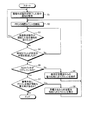
次に、本実施の形態にかかる画像形成装置の動作について説明する。図2は、本実施の形態にかかる画像形成装置の画像形成方法を示すフローチャートである。
(Image forming method)
Next, the operation of the image forming apparatus according to the present embodiment will be described. FIG. 2 is a flowchart showing an image forming method of the image forming apparatus according to the present embodiment.
初めに、プロコン要因監視部14は、プロコン制御部15から画像形成動作が終了した旨の通知を受領する(ステップS1)。次に、RTC13は、時間カウントを開始する(ステップS2)。
First, the process control
次に、プロコン要因監視部14は、プロコン制御部15から画像形成動作が開始した旨の通知を受けたか否かを判断する(ステップS3)。プロコン要因監視部14は、プロコン制御部15から画像形成動作が開始した旨の通知を受けたと判断した場合(ステップS3:Yes)、ステップS1へ戻る。
Next, the process control
一方、プロコン要因監視部14は、プロコン制御部15から画像形成動作が開始した旨の通知を受けていないと判断した場合(ステップS3:No)、RTC13による時間カウントが所定の時間を経過したか否かを判断する(ステップS4)。ここで、所定の時間とは、あらかじめ設定した時間であるが、例えば、数時間程度の時間が設定される。プロコン要因監視部14は、RTC13による時間カウントが所定の時間を経過していないと判断した場合(ステップS4:No)、ステップS3へ戻る。
On the other hand, if the process control
一方、プロコン要因監視部14は、RTC13による時間カウントが所定の時間を経過したと判断した場合(ステップS4:Yes)、ACスイッチ1がOFFしているか、すなわち、商用交流電源2が画像形成装置に接続されているか否かを判断する(ステップS5)。
On the other hand, if the process control
プロコン要因監視部14は、ACスイッチ1がOFFしていないと判断した場合(ステップS5:No)、プロコン制御部15は、商用交流電源からの電力供給によりプロコンを実行する(ステップS6)。具体的には、プロコン要因監視部14は、電圧検知回路3が電圧を検知している場合、プロコン制御部15へ所定の時間を経過した旨の通知を送り、それを受領したプロコン制御部15は、プロコンを行う。その後、ステップS2へ戻り以下のステップを繰り返す。
When the process control
一方、プロコン要因監視部14は、ACスイッチ1がOFFしていると判断した場合、すなわち、電圧検知回路3が電圧を検知しない場合(ステップS5:Yes)、蓄電手段17にプロコンを実行可能な電力量が蓄えられているか否かを判断する(ステップS7)。前述したように、プロコンを実行可能な電力量とは、プロコン制御系負荷6、プロコン駆動系負荷7、および、画像形成装置制御部10がプロコン動作可能な電力量のことである。そして、プロコン要因監視部14は、充電電圧検出回路18から入力された蓄電手段17の充電電圧から、蓄電手段17にプロコンを実行可能な電力量が蓄えられているか否かを判断する。
On the other hand, when it is determined that the AC switch 1 is OFF, that is, when the voltage detection circuit 3 does not detect the voltage (step S5: Yes), the process control
プロコン要因監視部14は、蓄電手段17にプロコンを実行可能な電力量が蓄えられていると判断した場合(ステップS7:Yes)、プロコン制御部15は、蓄電手段17からの蓄電力供給によりプロコンを実行する(ステップS8)。具体的には、プロコン要因監視部14が、蓄電出力放電部22に出力放電指示信号16を送信し、蓄電出力放電部22が蓄電手段17からの放電電力を定電圧生成回路23へ出力し、定電圧生成回路23が変圧した所定の直流電圧を、プロコン制御系負荷6、プロコン駆動系負荷7、および、画像形成装置制御部10へそれぞれ供給する。この結果、プロコンが行われる。その後、ステップS2へ戻り以下のステップを繰り返す。
When the process control
このように、プロコン要因監視部14は、RTC13による時間カウントが所定の時間を経過し、かつ、ACスイッチ1がOFFし、かつ、蓄電手段17にプロコンを実行可能な電力量が蓄えられていると判断した場合に、蓄電出力放電部22に出力放電指示信号16を送信する。
As described above, in the process control
一方、プロコン要因監視部14は、蓄電手段17にプロコンを実行可能な電力量が蓄えられていないと判断した場合(ステップS7:No)、処理を終了する。
On the other hand, if the process control
図3は、画像形成装置制御部10による制御シーケンスを示した図である。商用交流電源2が入力されている状態では、画像形成動作の終了後に0から時間がカウントされ、所定時間が未経過の段階で再度画像形成動作が行われると再度0から時間がカウントされる。そして、図示されていないが、所定時間が経過した段階で、商用交流電源2からの電力供給によりプロコンが実行される。
FIG. 3 is a diagram showing a control sequence by the image forming
また、商用交流電源2が入力されていない状態、すなわち、画像形成装置がシャットダウンしている状態でもカウントは継続する。そして、所定時間が経過した段階で蓄電手段17からの電力供給によりプロコンが実行される。プロコンの終了後に再度カウント0から時間がカウントされるが、本例では、既に蓄電手段17にプロコンを実行可能な電力量が蓄えられていないので次に所定時間が経過してもプロコンは実行されない。 The counting continues even when the commercial AC power supply 2 is not input, that is, when the image forming apparatus is shut down. Then, when the predetermined time has passed, the process control is executed by supplying power from the power storage means 17. Although the time is counted again from 0 after the completion of the process control, in this example, since the amount of power that can be used to execute the process control is not already stored in the power storage means 17, the process control is not executed even if the next predetermined time elapses. .
図4は、従来の画像形成装置と本実施の形態にかかる画像形成装置とにおけるACスイッチ1ON後の動作フローの違いを示す図である。図の方式AおよびBは、従来の画像形成装置の動作フローを示している。方式Aは、定着起動とプロコンを並行して行う方式である。プロコンを実行している間は、定着起動に必要な電力をプロコンに必要な電力分減らしているため、定着装置部の昇温効率が悪くなり、定着リロード終了までの時間が長くなっている。方式Bは、定着リロード後にプロコン行う方式である。定着リロード終了後に、プロコンを実行するため、プロコン実行終了後に、プリント動作が可能となるが、プリント動作が可能となるまでの時間は方式Aと変わらない。 FIG. 4 is a diagram illustrating a difference in operation flow after the AC switch 1 is turned on between the conventional image forming apparatus and the image forming apparatus according to the present embodiment. The schemes A and B in the figure show the operation flow of the conventional image forming apparatus. System A is a system in which fixing start-up and process control are performed in parallel. While the process control is being executed, the power required for starting the fixing is reduced by the power required for the process control, so that the temperature rise efficiency of the fixing device is deteriorated, and the time until the fixing reload ends is increased. The system B is a system that performs a process control after fixing reload. Since the process control is executed after the fixing reload is completed, the printing operation is possible after the execution of the process control. However, the time until the printing operation is enabled is the same as that in the method A.
一方、図の方式Cは、本実施の形態にかかる画像形成装置の動作フローを示している。方式Cは、画像形成装置がシャットダウンしている状態でも継続的にプロコンが行われているので、ACスイッチ1をONしてもプロコンを実行する必要がない。このため、方式AおよびBに比べて、ACスイッチ1のONからプリント動作が可能となるまでの時間は、プロコン実行時間分だけ短縮することができる。 On the other hand, method C in the figure shows an operation flow of the image forming apparatus according to the present embodiment. In the system C, since the process control is continuously performed even when the image forming apparatus is shut down, it is not necessary to execute the process control even when the AC switch 1 is turned on. For this reason, as compared with the systems A and B, the time from when the AC switch 1 is turned on until the printing operation is possible can be shortened by the execution time of the process controller.
このように、プロコンを実行可能な蓄電量がある場合は、主電源入力がOFFの間でも何度も蓄電手段17の蓄電力によりプロコンを行うことができるので、長期間電源入力がOFFであった状態から朝1番などに電源入力をONする場合でも、プロコンを行う必要がないので、プリント動作が可能となるまでの時間を短縮することが可能となる。 As described above, when there is an amount of stored electricity that can execute the process control, since the process control can be performed by the stored power of the power storage means 17 many times even when the main power input is OFF, the power supply input is OFF for a long time. Even when the power input is turned on in the morning in the morning, etc., since it is not necessary to perform the process control, it is possible to shorten the time until the printing operation becomes possible.
なお、本実施の形態では、電圧検知回路3は、ACスイッチ1の後段に設けられているが、ACスイッチ1がOFFの時には電圧が入力されない仕様であれば、ACスイッチ1の前段に設けられてもよい。 In this embodiment, the voltage detection circuit 3 is provided at the subsequent stage of the AC switch 1. However, if the specification is such that no voltage is input when the AC switch 1 is OFF, the voltage detection circuit 3 is provided at the previous stage of the AC switch 1. May be.
また、本実施の形態では、プロコン要因監視部14は、RTC13による時間カウントが所定の時間を経過したと判断し、かつ、ACスイッチ1がOFFしていると判断し、かつ、蓄電手段17にプロコンを実行可能な電力量が蓄えられていると判断した場合に、蓄電手段17からの放電電力を定電圧生成回路23へ出力するように蓄電出力放電部22を制御している。これに対し、プロコン要因監視部14は、RTC13による時間カウントが所定の時間を経過したと判断し、かつ、ACスイッチ1がOFFしていると判断した場合、蓄電手段17の電力量を確認せずに、蓄電手段17からの放電電力を定電圧生成回路23へ出力するように蓄電出力放電部22を制御するようにしてもよい。
Further, in the present embodiment, the process control
(変形例1)
本実施の形態では、主電源入力OFF時にプロコンを行う場合には、蓄電手段の蓄電力を画像形成装置制御部全体へ供給しているが、変形例1では、主電源入力OFF時にプロコンを行う場合には、蓄電手段の蓄電力を画像形成装置制御部のプロコン制御部のみに供給する。
(Modification 1)
In the present embodiment, when the process control is performed when the main power supply input is OFF, the stored power of the power storage unit is supplied to the entire image forming apparatus control unit. However, in Modification 1, the process control is performed when the main power input is OFF. In this case, the power stored in the power storage means is supplied only to the process control unit of the image forming apparatus control unit.
図5は、変形例1にかかる画像形成装置の電力供給を示す機能図である。変形例1では、コンバータ5から画像形成装置制御部10への電力供給が、プロコン制御部15と、それ以外との2系統に分かれている。さらに、定電圧生成回路23からの電力供給が、画像形成装置制御部10全体ではなく、プロコン制御部15だけとなっている。なお、その他の構成については、本実施の形態にかかる画像形成装置と同じである。
FIG. 5 is a functional diagram illustrating power supply of the image forming apparatus according to the first modification. In the first modification, power supply from the
従って、プロコン制御部15には、商用交流電源2からの電力と、蓄電手段17からの電力とが供給されるが、プロコン制御部15以外の画像形成装置制御部10には、商用交流電源2からの電力だけが供給される。
Accordingly, the power from the commercial AC power source 2 and the power from the power storage unit 17 are supplied to the
このような構成をとることにより、画像形成装置に商用交流電源2から電力が供給されている間は、画像形成装置制御部10全体に電力が供給されるが、画像形成装置に商用交流電源2から電力が供給されていない状態でプロコンを行う場合(図2のステップS8の場合)には、蓄電手段17からの電力はプロコン制御部15にしか供給されない。
By adopting such a configuration, while power is supplied from the commercial AC power supply 2 to the image forming apparatus, power is supplied to the entire image forming
このように、主電源入力OFF時におけるプロコン時において、プロコン動作に最小限必要な電力のみを画像形成装置制御部10へ供給することができるので、蓄電手段17からの電力供給量を削減し、蓄電手段17の電力を有効活用することが可能となる。
In this way, at the time of the process control when the main power input is turned off, only the minimum power required for the process control operation can be supplied to the image forming
(変形例2)
変形例2では、プロコン要因監視部14の機能を無効にするスイッチがさらに備えられ、状況に応じてプロコンの実施を制限することができる。図6は、変形例2にかかる画像形成装置の電力供給を示す機能図である。変形例2では、プロコン要因監視部14と充電電圧検出回路18の間に、切替えスイッチ27が備えられている。なお、その他の構成については、本実施の形態にかかる画像形成装置と同じである。
(Modification 2)
In the second modification, a switch for disabling the function of the process control
切替えスイッチ27がONとなっている場合、プロコン要因監視部14の機能は有効であるので、変形例2にかかる画像形成装置は本実施の形態にかかる画像形成装置と全く同じに動作する。しかし、切替えスイッチ27がOFFとなっている場合、プロコン要因監視部14は充電電圧検出回路18から蓄電手段17の充電電圧を知ることができず、常に、蓄電手段17にプロコンを実行可能な電力量が蓄えられていないと判断する(図2のステップS7で、常にNoと判断する)。従って、プロコン要因監視部14の機能は無効となり、プロコン制御部15によるプロコンは実行されない。
When the
これにより、蓄電手段17の蓄電力で行うプロコン動作を、必要に応じて制限することができる。例えば、画像形成装置の搬送時には切替えスイッチ27をOFFにした状態で搬送を行うことにより、搬送中にプロコンが実行されることを防止することができるので、安全性を確保することが可能となる。
Thereby, the process control operation | movement performed with the electrical storage of the electrical storage means 17 can be restrict | limited as needed. For example, when the image forming apparatus is transported, transport is performed in a state where the
なお、切替えスイッチ27を、プロコン要因監視部14と充電電圧検出回路18の間ではなく、プロコン要因監視部14と電圧検知回路3の間、又は、プロコン要因監視部14とRTC13の間に備えても、同様に、プロコン制御部15によるプロコンの実施を制限することができる。
In addition, the
また、切替えスイッチ27を、プロコン要因監視部14と蓄電出力放電部22の間に備えた場合は、プロコン要因監視部14の機能は有効の状態であるが、蓄電出力放電部22が出力放電指示信号16を受信することができないので、同様に、プロコン制御部15によるプロコンの実施を制限することができる。
When the
また、画像形成装置の操作部(図示せず)からプロコン要因監視部14の機能の有効又は無効を設定できるようにし、その情報を画像形成装置のコントローラ部11に記憶させて、プロコン要因監視部14の機能を切り替えるようにしてもよい。
Further, it is possible to enable or disable the function of the process control
(変形例3)
変形例3では、プロコン要因監視部14に蓄電手段17からの蓄電力供給を制限するトランジスタがさらに備えられ、プロコン要因監視部14への蓄電力供給を制限し、プロコン要因監視部14への電力供給を切り替えることができる。
(Modification 3)
In the third modification, the process control
図7は、変形例3にかかる画像形成装置の電力供給を示す機能図である。変形例3では、蓄電手段17とプロコン要因監視部14の間に、トランジスタ28が備えられている。そして、蓄電手段17の出力がトランジスタ28のエミッタ、電圧検知回路3の出力がトランジスタ28のベースにそれぞれ入力され、トランジスタ28のコレクタがプロコン要因監視部14へ入力されている。なお、その他の構成については、本実施の形態にかかる画像形成装置と同じである。
FIG. 7 is a functional diagram illustrating power supply of the image forming apparatus according to the third modification. In the third modification, a
従って、ACスイッチ1がONしており、電圧検知回路3が電圧を検知している間は、トランジスタ28はOFFしており、プロコン要因監視部14へ蓄電手段17の蓄電力は供給されない。しかし、ACスイッチ1がOFFし、電圧検知回路3が電圧を検知しなくなると、トランジスタ28がONし、蓄電手段17の蓄電力がトランジスタ28のコレクタからプロコン要因監視部14へ供給される。
Therefore, while the AC switch 1 is ON and the voltage detection circuit 3 is detecting the voltage, the
このように、プロコン要因監視部14への電力供給を、商用交流電源2が入力されている場合は商用交流電源2からの供給、商用交流電源2が入力されていない場合は蓄電手段17からの供給と切り替えることができるので、蓄電手段17の蓄電力の無駄な消費を削減し、蓄電力を有効活用することが可能となる。
In this way, the power supply to the process control
このように、本実施の形態にかかる画像形成装置によれば、プロコン要因監視部が、商用交流電源からの電力供給が無いと判断し、かつ、画像形成動作終了後の経過時間が所定の時間を越えたと判断した場合、蓄電手段の蓄電力をプロコン制御手段へ出力させることができるので、商用電源のOFF中に蓄電手段の蓄電力を用いてプロコンを行うことができ、長期間電源入力がOFFであった状態から朝1番などに電源入力をONする場合でもプロコンを行う必要がないので、プリント動作が可能となるまでの時間を短縮することがが可能となる。 As described above, according to the image forming apparatus of the present embodiment, the process control factor monitoring unit determines that there is no power supply from the commercial AC power source, and the elapsed time after the end of the image forming operation is a predetermined time. If it is determined that the power storage means has exceeded, the stored power of the power storage means can be output to the process control control means. Even when the power input is turned on in the morning, etc. from the state of being off, it is not necessary to perform the process control, so that it is possible to reduce the time until the printing operation becomes possible.
なお、上記実施の形態では、本発明の画像形成装置を、コピー機能、プリンタ機能、スキャナ機能およびファクシミリ機能のうち少なくとも2つの機能を有する複合機に適用した例を挙げて説明するが、複写機、プリンタ、スキャナ装置、ファクシミリ装置等の画像形成装置であればいずれにも適用することができる。 In the above embodiment, the image forming apparatus of the present invention will be described by taking an example in which the image forming apparatus is applied to a multifunction machine having at least two functions among a copy function, a printer function, a scanner function, and a facsimile function. The present invention can be applied to any image forming apparatus such as a printer, a scanner apparatus, and a facsimile apparatus.
1 ACスイッチ
2 商用交流電源
3 電圧検知回路
4 整流平滑回路
5 コンバータ
6 プロコン制御系負荷
7 プロコン駆動系負荷
8 エンジン制御系負荷
9 エンジン駆動系負荷
10 画像形成装置制御部
11 コントローラ部
12 エンジン制御部
13 RTC(Real Time Clock)
14 プロコン要因監視部
15 プロコン制御部
16 出力放電指示信号
17 蓄電手段
18 充電電圧検出回路
19 充電電流検出回路
20 充電制御回路
21 充電指示信号
22 蓄電出力放電部
23 定電圧生成回路
24、25、26 ダイオード
27 切替えスイッチ
28 トランジスタ
DESCRIPTION OF SYMBOLS 1 AC switch 2 Commercial AC power supply 3 Voltage detection circuit 4
DESCRIPTION OF
Claims (9)
画像形成動作終了後の経過時間を測定する測定手段と、
充放電が可能な蓄電手段と、
形成する画像の画質を調整するプロセスコントロールの実行を制御するプロセスコントロール制御手段と、
前記検知手段および前記測定手段の状態を監視し、前記電力供給が無いと判断し、かつ、前記画像形成動作終了後の経過時間が所定の時間を越えたと判断した場合、前記蓄電手段の蓄電力を前記プロセスコントロール制御手段へ出力させるプロセスコントロール要因監視手段と、を備え、
前記蓄電手段は、前記プロセスコントロール要因監視手段へ前記蓄電力を出力すること、
を特徴とする画像形成装置。 Detection means for detecting the presence or absence of power supply from the power source;
A measuring means for measuring an elapsed time after completion of the image forming operation;
Power storage means capable of charging and discharging;
Process control control means for controlling execution of process control for adjusting the image quality of the image to be formed;
When the states of the detection unit and the measurement unit are monitored, it is determined that the power supply is not present, and it is determined that the elapsed time after the end of the image forming operation has exceeded a predetermined time, Process control factor monitoring means for outputting to the process control control means ,
The power storage means outputs the stored power to the process control factor monitoring means;
An image forming apparatus.
前記プロセスコントロール要因監視手段は、前記蓄電量検出手段の状態をさらに監視し、前記電力供給が無いと判断し、かつ、前記画像形成動作終了後の経過時間が所定の時間を越えたと判断し、かつ、前記蓄電量が前記プロセスコントロールを実行可能な量であると判断した場合、前記蓄電手段の前記蓄電力を前記プロセスコントロール制御手段へ出力させること、
を特徴とする請求項1に記載の画像形成装置。 A storage amount detecting means for detecting a storage amount of the storage means;
The process control factor monitoring means further monitors the state of the charged amount detection means, determines that there is no power supply, and determines that the elapsed time after the end of the image forming operation has exceeded a predetermined time, And when it is determined that the amount of stored electricity is an amount capable of executing the process control, the stored power of the power storage unit is output to the process control control unit,
The image forming apparatus according to claim 1.
前記プロセスコントロール要因監視手段は、前記電力供給が無いと判断し、かつ、前記プロセスコントロール終了後の経過時間が前記所定の時間を越えたと判断し、かつ、前記蓄電量が前記プロセスコントロールを実行可能な量であると判断した場合、前記蓄電手段の前記蓄電力を前記プロセスコントロール制御手段へ出力させること、
を特徴とする請求項2に記載の画像形成装置。 The measuring means further measures an elapsed time after the end of the process control;
The process control factor monitoring means determines that the power supply is not present, determines that the elapsed time after the end of the process control has exceeded the predetermined time, and allows the stored power to execute the process control If it is determined that the amount is a small amount, the stored power of the power storage means is output to the process control control means,
The image forming apparatus according to claim 2.
プロセスコントロール要因監視手段は、前記蓄電手段の蓄電力をさらに前記実行手段へ出力させること、
を特徴とする請求項1〜6のいずれか一項に記載の画像形成装置。 The process control factor monitoring means further comprises execution means for executing process control, causing the execution means to further output the stored power of the power storage means,
The image forming apparatus according to claim 1 , wherein:
電源からの電力供給の有無を検知する検知ステップと、
画像形成動作終了後の経過時間を測定する測定ステップと、
蓄電手段に充電を行う蓄電ステップと、
形成する画像の画質を調整するプロセスコントロールの実行を制御するプロセスコントロール制御ステップと、
前記蓄電手段から蓄電力が供給されるプロセスコントロール要因監視手段が、前記検知ステップで前記電力供給が無いと判断し、かつ、前記測定ステップで前記経過時間が所定の時間を越えたと判断した場合、前記蓄電手段の蓄電力を前記プロセスコントロール制御ステップで使用させる蓄電力使用ステップと、を含むこと、
を特徴とする画像形成方法。 An image forming method executed by an image forming apparatus,
A detection step for detecting the presence or absence of power supply from the power source;
A measuring step for measuring an elapsed time after the image forming operation is completed;
A power storage step of charging the power storage means ;
A process control control step for controlling execution of a process control for adjusting an image quality of an image to be formed;
When the process control factor monitoring means to which the stored power is supplied from the power storage means determines that the power supply is not present in the detection step and determines that the elapsed time has exceeded a predetermined time in the measurement step, A stored power use step for causing the stored power of the power storage means to be used in the process control control step,
An image forming method.
Priority Applications (1)
| Application Number | Priority Date | Filing Date | Title |
|---|---|---|---|
| JP2009053486A JP5304332B2 (en) | 2009-03-06 | 2009-03-06 | Image forming apparatus and image forming method |
Applications Claiming Priority (1)
| Application Number | Priority Date | Filing Date | Title |
|---|---|---|---|
| JP2009053486A JP5304332B2 (en) | 2009-03-06 | 2009-03-06 | Image forming apparatus and image forming method |
Publications (2)
| Publication Number | Publication Date |
|---|---|
| JP2010210667A JP2010210667A (en) | 2010-09-24 |
| JP5304332B2 true JP5304332B2 (en) | 2013-10-02 |
Family
ID=42970937
Family Applications (1)
| Application Number | Title | Priority Date | Filing Date |
|---|---|---|---|
| JP2009053486A Expired - Fee Related JP5304332B2 (en) | 2009-03-06 | 2009-03-06 | Image forming apparatus and image forming method |
Country Status (1)
| Country | Link |
|---|---|
| JP (1) | JP5304332B2 (en) |
Family Cites Families (9)
| Publication number | Priority date | Publication date | Assignee | Title |
|---|---|---|---|---|
| JP3098138B2 (en) * | 1993-07-06 | 2000-10-16 | キヤノン株式会社 | Image forming device |
| JP3409406B2 (en) * | 1993-12-28 | 2003-05-26 | カシオ電子工業株式会社 | Image forming device |
| JP3426148B2 (en) * | 1998-12-18 | 2003-07-14 | 富士通株式会社 | Image forming device |
| JP4365052B2 (en) * | 2001-07-17 | 2009-11-18 | 株式会社リコー | Image forming apparatus |
| JP4341209B2 (en) * | 2002-06-11 | 2009-10-07 | コニカミノルタホールディングス株式会社 | Image forming apparatus and image forming method |
| JP2004074558A (en) * | 2002-08-16 | 2004-03-11 | Ricoh Co Ltd | Image formation apparatus |
| JP4402972B2 (en) * | 2004-02-05 | 2010-01-20 | 株式会社リコー | Image forming apparatus |
| JP2007072246A (en) * | 2005-09-08 | 2007-03-22 | Ricoh Co Ltd | Image forming apparatus |
| JP5000927B2 (en) * | 2006-01-05 | 2012-08-15 | 株式会社リコー | Image forming apparatus |
-
2009
- 2009-03-06 JP JP2009053486A patent/JP5304332B2/en not_active Expired - Fee Related
Also Published As
| Publication number | Publication date |
|---|---|
| JP2010210667A (en) | 2010-09-24 |
Similar Documents
| Publication | Publication Date | Title |
|---|---|---|
| US7734937B2 (en) | Power supply device capable of supplying large amount of power necessary for entire system operation | |
| JP4148943B2 (en) | Auxiliary power supply device, fixing device, image forming apparatus, and charging operation control method | |
| US8270862B2 (en) | Image forming apparatus and method for controlling fuser thereof | |
| US20090309423A1 (en) | Charging control apparatus and method for controlling the same | |
| JP6323206B2 (en) | Image forming apparatus, image forming method, and program | |
| JP5121403B2 (en) | Image forming apparatus and power supply method | |
| JP5540769B2 (en) | Power supply device and image forming apparatus | |
| JP2004117468A (en) | Image forming apparatus | |
| JP2006288090A (en) | Capacitor apparatus, charging method for the same and image forming apparatus | |
| JP2015023603A (en) | Charge control device, image forming apparatus, charge control method, and program | |
| JP5304332B2 (en) | Image forming apparatus and image forming method | |
| JP2015018028A (en) | Image forming apparatus | |
| JP2017070183A (en) | Power supply device, image forming apparatus, and power supply voltage monitoring method | |
| JP2004078155A (en) | Image forming device | |
| JP5637275B2 (en) | Power supply device and image forming apparatus | |
| JP2014077940A (en) | Fixation power source control apparatus, image forming apparatus, fixation power source control method, and fixation power source control program | |
| JP5211965B2 (en) | Image forming apparatus | |
| JP5365281B2 (en) | Image forming apparatus | |
| JP5369566B2 (en) | Power supply device and image forming apparatus | |
| JP5752895B2 (en) | Image forming apparatus | |
| JP5760553B2 (en) | Power supply device, electronic device, and image forming apparatus | |
| JP4948937B2 (en) | Image forming apparatus | |
| JP4823819B2 (en) | Fixing apparatus and image forming apparatus | |
| JP4643363B2 (en) | Image forming apparatus | |
| JP2004304866A (en) | Power supply unit and image-forming apparatus |
Legal Events
| Date | Code | Title | Description |
|---|---|---|---|
| A621 | Written request for application examination |
Free format text: JAPANESE INTERMEDIATE CODE: A621 Effective date: 20120130 |
|
| A521 | Written amendment |
Free format text: JAPANESE INTERMEDIATE CODE: A523 Effective date: 20120620 |
|
| A977 | Report on retrieval |
Free format text: JAPANESE INTERMEDIATE CODE: A971007 Effective date: 20121228 |
|
| A131 | Notification of reasons for refusal |
Free format text: JAPANESE INTERMEDIATE CODE: A131 Effective date: 20130108 |
|
| A521 | Written amendment |
Free format text: JAPANESE INTERMEDIATE CODE: A523 Effective date: 20130311 |
|
| TRDD | Decision of grant or rejection written | ||
| A01 | Written decision to grant a patent or to grant a registration (utility model) |
Free format text: JAPANESE INTERMEDIATE CODE: A01 Effective date: 20130528 |
|
| A61 | First payment of annual fees (during grant procedure) |
Free format text: JAPANESE INTERMEDIATE CODE: A61 Effective date: 20130610 |
|
| R151 | Written notification of patent or utility model registration |
Ref document number: 5304332 Country of ref document: JP Free format text: JAPANESE INTERMEDIATE CODE: R151 |
|
| LAPS | Cancellation because of no payment of annual fees |