JP5302895B2 - Power generation method - Google Patents
Power generation method Download PDFInfo
- Publication number
- JP5302895B2 JP5302895B2 JP2009541633A JP2009541633A JP5302895B2 JP 5302895 B2 JP5302895 B2 JP 5302895B2 JP 2009541633 A JP2009541633 A JP 2009541633A JP 2009541633 A JP2009541633 A JP 2009541633A JP 5302895 B2 JP5302895 B2 JP 5302895B2
- Authority
- JP
- Japan
- Prior art keywords
- stream
- gas stream
- flue gas
- oxygen
- steam
- Prior art date
- Legal status (The legal status is an assumption and is not a legal conclusion. Google has not performed a legal analysis and makes no representation as to the accuracy of the status listed.)
- Expired - Fee Related
Links
Images


Classifications
-
- B—PERFORMING OPERATIONS; TRANSPORTING
- B01—PHYSICAL OR CHEMICAL PROCESSES OR APPARATUS IN GENERAL
- B01D—SEPARATION
- B01D53/00—Separation of gases or vapours; Recovering vapours of volatile solvents from gases; Chemical or biological purification of waste gases, e.g. engine exhaust gases, smoke, fumes, flue gases, aerosols
- B01D53/34—Chemical or biological purification of waste gases
- B01D53/74—General processes for purification of waste gases; Apparatus or devices specially adapted therefor
- B01D53/75—Multi-step processes
-
- F—MECHANICAL ENGINEERING; LIGHTING; HEATING; WEAPONS; BLASTING
- F01—MACHINES OR ENGINES IN GENERAL; ENGINE PLANTS IN GENERAL; STEAM ENGINES
- F01K—STEAM ENGINE PLANTS; STEAM ACCUMULATORS; ENGINE PLANTS NOT OTHERWISE PROVIDED FOR; ENGINES USING SPECIAL WORKING FLUIDS OR CYCLES
- F01K25/00—Plants or engines characterised by use of special working fluids, not otherwise provided for; Plants operating in closed cycles and not otherwise provided for
- F01K25/08—Plants or engines characterised by use of special working fluids, not otherwise provided for; Plants operating in closed cycles and not otherwise provided for using special vapours
-
- C—CHEMISTRY; METALLURGY
- C01—INORGANIC CHEMISTRY
- C01B—NON-METALLIC ELEMENTS; COMPOUNDS THEREOF; METALLOIDS OR COMPOUNDS THEREOF NOT COVERED BY SUBCLASS C01C
- C01B13/00—Oxygen; Ozone; Oxides or hydroxides in general
- C01B13/02—Preparation of oxygen
- C01B13/0229—Purification or separation processes
- C01B13/0248—Physical processing only
- C01B13/0251—Physical processing only by making use of membranes
-
- C—CHEMISTRY; METALLURGY
- C10—PETROLEUM, GAS OR COKE INDUSTRIES; TECHNICAL GASES CONTAINING CARBON MONOXIDE; FUELS; LUBRICANTS; PEAT
- C10J—PRODUCTION OF PRODUCER GAS, WATER-GAS, SYNTHESIS GAS FROM SOLID CARBONACEOUS MATERIAL, OR MIXTURES CONTAINING THESE GASES; CARBURETTING AIR OR OTHER GASES
- C10J3/00—Production of combustible gases containing carbon monoxide from solid carbonaceous fuels
- C10J3/02—Fixed-bed gasification of lump fuel
- C10J3/06—Continuous processes
-
- C—CHEMISTRY; METALLURGY
- C10—PETROLEUM, GAS OR COKE INDUSTRIES; TECHNICAL GASES CONTAINING CARBON MONOXIDE; FUELS; LUBRICANTS; PEAT
- C10J—PRODUCTION OF PRODUCER GAS, WATER-GAS, SYNTHESIS GAS FROM SOLID CARBONACEOUS MATERIAL, OR MIXTURES CONTAINING THESE GASES; CARBURETTING AIR OR OTHER GASES
- C10J3/00—Production of combustible gases containing carbon monoxide from solid carbonaceous fuels
- C10J3/46—Gasification of granular or pulverulent flues in suspension
- C10J3/466—Entrained flow processes
-
- C—CHEMISTRY; METALLURGY
- C10—PETROLEUM, GAS OR COKE INDUSTRIES; TECHNICAL GASES CONTAINING CARBON MONOXIDE; FUELS; LUBRICANTS; PEAT
- C10K—PURIFYING OR MODIFYING THE CHEMICAL COMPOSITION OF COMBUSTIBLE GASES CONTAINING CARBON MONOXIDE
- C10K1/00—Purifying combustible gases containing carbon monoxide
- C10K1/002—Removal of contaminants
- C10K1/003—Removal of contaminants of acid contaminants, e.g. acid gas removal
- C10K1/004—Sulfur containing contaminants, e.g. hydrogen sulfide
-
- C—CHEMISTRY; METALLURGY
- C10—PETROLEUM, GAS OR COKE INDUSTRIES; TECHNICAL GASES CONTAINING CARBON MONOXIDE; FUELS; LUBRICANTS; PEAT
- C10K—PURIFYING OR MODIFYING THE CHEMICAL COMPOSITION OF COMBUSTIBLE GASES CONTAINING CARBON MONOXIDE
- C10K1/00—Purifying combustible gases containing carbon monoxide
- C10K1/02—Dust removal
- C10K1/024—Dust removal by filtration
-
- C—CHEMISTRY; METALLURGY
- C10—PETROLEUM, GAS OR COKE INDUSTRIES; TECHNICAL GASES CONTAINING CARBON MONOXIDE; FUELS; LUBRICANTS; PEAT
- C10K—PURIFYING OR MODIFYING THE CHEMICAL COMPOSITION OF COMBUSTIBLE GASES CONTAINING CARBON MONOXIDE
- C10K3/00—Modifying the chemical composition of combustible gases containing carbon monoxide to produce an improved fuel, e.g. one of different calorific value, which may be free from carbon monoxide
- C10K3/001—Modifying the chemical composition of combustible gases containing carbon monoxide to produce an improved fuel, e.g. one of different calorific value, which may be free from carbon monoxide by thermal treatment
- C10K3/003—Reducing the tar content
- C10K3/005—Reducing the tar content by partial oxidation
-
- F—MECHANICAL ENGINEERING; LIGHTING; HEATING; WEAPONS; BLASTING
- F01—MACHINES OR ENGINES IN GENERAL; ENGINE PLANTS IN GENERAL; STEAM ENGINES
- F01K—STEAM ENGINE PLANTS; STEAM ACCUMULATORS; ENGINE PLANTS NOT OTHERWISE PROVIDED FOR; ENGINES USING SPECIAL WORKING FLUIDS OR CYCLES
- F01K19/00—Regenerating or otherwise treating steam exhausted from steam engine plant
- F01K19/02—Regenerating by compression
- F01K19/04—Regenerating by compression in combination with cooling or heating
-
- F—MECHANICAL ENGINEERING; LIGHTING; HEATING; WEAPONS; BLASTING
- F01—MACHINES OR ENGINES IN GENERAL; ENGINE PLANTS IN GENERAL; STEAM ENGINES
- F01K—STEAM ENGINE PLANTS; STEAM ACCUMULATORS; ENGINE PLANTS NOT OTHERWISE PROVIDED FOR; ENGINES USING SPECIAL WORKING FLUIDS OR CYCLES
- F01K23/00—Plants characterised by more than one engine delivering power external to the plant, the engines being driven by different fluids
- F01K23/02—Plants characterised by more than one engine delivering power external to the plant, the engines being driven by different fluids the engine cycles being thermally coupled
- F01K23/06—Plants characterised by more than one engine delivering power external to the plant, the engines being driven by different fluids the engine cycles being thermally coupled combustion heat from one cycle heating the fluid in another cycle
- F01K23/067—Plants characterised by more than one engine delivering power external to the plant, the engines being driven by different fluids the engine cycles being thermally coupled combustion heat from one cycle heating the fluid in another cycle the combustion heat coming from a gasification or pyrolysis process, e.g. coal gasification
- F01K23/068—Plants characterised by more than one engine delivering power external to the plant, the engines being driven by different fluids the engine cycles being thermally coupled combustion heat from one cycle heating the fluid in another cycle the combustion heat coming from a gasification or pyrolysis process, e.g. coal gasification in combination with an oxygen producing plant, e.g. an air separation plant
-
- F—MECHANICAL ENGINEERING; LIGHTING; HEATING; WEAPONS; BLASTING
- F01—MACHINES OR ENGINES IN GENERAL; ENGINE PLANTS IN GENERAL; STEAM ENGINES
- F01K—STEAM ENGINE PLANTS; STEAM ACCUMULATORS; ENGINE PLANTS NOT OTHERWISE PROVIDED FOR; ENGINES USING SPECIAL WORKING FLUIDS OR CYCLES
- F01K27/00—Plants for converting heat or fluid energy into mechanical energy, not otherwise provided for
-
- B—PERFORMING OPERATIONS; TRANSPORTING
- B01—PHYSICAL OR CHEMICAL PROCESSES OR APPARATUS IN GENERAL
- B01D—SEPARATION
- B01D2256/00—Main component in the product gas stream after treatment
- B01D2256/22—Carbon dioxide
-
- B—PERFORMING OPERATIONS; TRANSPORTING
- B01—PHYSICAL OR CHEMICAL PROCESSES OR APPARATUS IN GENERAL
- B01D—SEPARATION
- B01D2257/00—Components to be removed
- B01D2257/30—Sulfur compounds
- B01D2257/302—Sulfur oxides
-
- B—PERFORMING OPERATIONS; TRANSPORTING
- B01—PHYSICAL OR CHEMICAL PROCESSES OR APPARATUS IN GENERAL
- B01D—SEPARATION
- B01D2257/00—Components to be removed
- B01D2257/80—Water
-
- B—PERFORMING OPERATIONS; TRANSPORTING
- B01—PHYSICAL OR CHEMICAL PROCESSES OR APPARATUS IN GENERAL
- B01D—SEPARATION
- B01D2259/00—Type of treatment
- B01D2259/40—Further details for adsorption processes and devices
-
- B—PERFORMING OPERATIONS; TRANSPORTING
- B01—PHYSICAL OR CHEMICAL PROCESSES OR APPARATUS IN GENERAL
- B01D—SEPARATION
- B01D53/00—Separation of gases or vapours; Recovering vapours of volatile solvents from gases; Chemical or biological purification of waste gases, e.g. engine exhaust gases, smoke, fumes, flue gases, aerosols
- B01D53/34—Chemical or biological purification of waste gases
- B01D53/74—General processes for purification of waste gases; Apparatus or devices specially adapted therefor
- B01D53/77—Liquid phase processes
-
- C—CHEMISTRY; METALLURGY
- C01—INORGANIC CHEMISTRY
- C01B—NON-METALLIC ELEMENTS; COMPOUNDS THEREOF; METALLOIDS OR COMPOUNDS THEREOF NOT COVERED BY SUBCLASS C01C
- C01B2210/00—Purification or separation of specific gases
- C01B2210/0043—Impurity removed
- C01B2210/0046—Nitrogen
-
- C—CHEMISTRY; METALLURGY
- C10—PETROLEUM, GAS OR COKE INDUSTRIES; TECHNICAL GASES CONTAINING CARBON MONOXIDE; FUELS; LUBRICANTS; PEAT
- C10J—PRODUCTION OF PRODUCER GAS, WATER-GAS, SYNTHESIS GAS FROM SOLID CARBONACEOUS MATERIAL, OR MIXTURES CONTAINING THESE GASES; CARBURETTING AIR OR OTHER GASES
- C10J2300/00—Details of gasification processes
- C10J2300/09—Details of the feed, e.g. feeding of spent catalyst, inert gas or halogens
- C10J2300/0913—Carbonaceous raw material
- C10J2300/093—Coal
-
- C—CHEMISTRY; METALLURGY
- C10—PETROLEUM, GAS OR COKE INDUSTRIES; TECHNICAL GASES CONTAINING CARBON MONOXIDE; FUELS; LUBRICANTS; PEAT
- C10J—PRODUCTION OF PRODUCER GAS, WATER-GAS, SYNTHESIS GAS FROM SOLID CARBONACEOUS MATERIAL, OR MIXTURES CONTAINING THESE GASES; CARBURETTING AIR OR OTHER GASES
- C10J2300/00—Details of gasification processes
- C10J2300/09—Details of the feed, e.g. feeding of spent catalyst, inert gas or halogens
- C10J2300/0953—Gasifying agents
- C10J2300/0959—Oxygen
-
- C—CHEMISTRY; METALLURGY
- C10—PETROLEUM, GAS OR COKE INDUSTRIES; TECHNICAL GASES CONTAINING CARBON MONOXIDE; FUELS; LUBRICANTS; PEAT
- C10J—PRODUCTION OF PRODUCER GAS, WATER-GAS, SYNTHESIS GAS FROM SOLID CARBONACEOUS MATERIAL, OR MIXTURES CONTAINING THESE GASES; CARBURETTING AIR OR OTHER GASES
- C10J2300/00—Details of gasification processes
- C10J2300/09—Details of the feed, e.g. feeding of spent catalyst, inert gas or halogens
- C10J2300/0953—Gasifying agents
- C10J2300/0973—Water
-
- C—CHEMISTRY; METALLURGY
- C10—PETROLEUM, GAS OR COKE INDUSTRIES; TECHNICAL GASES CONTAINING CARBON MONOXIDE; FUELS; LUBRICANTS; PEAT
- C10J—PRODUCTION OF PRODUCER GAS, WATER-GAS, SYNTHESIS GAS FROM SOLID CARBONACEOUS MATERIAL, OR MIXTURES CONTAINING THESE GASES; CARBURETTING AIR OR OTHER GASES
- C10J2300/00—Details of gasification processes
- C10J2300/16—Integration of gasification processes with another plant or parts within the plant
- C10J2300/1603—Integration of gasification processes with another plant or parts within the plant with gas treatment
- C10J2300/1606—Combustion processes
-
- C—CHEMISTRY; METALLURGY
- C10—PETROLEUM, GAS OR COKE INDUSTRIES; TECHNICAL GASES CONTAINING CARBON MONOXIDE; FUELS; LUBRICANTS; PEAT
- C10J—PRODUCTION OF PRODUCER GAS, WATER-GAS, SYNTHESIS GAS FROM SOLID CARBONACEOUS MATERIAL, OR MIXTURES CONTAINING THESE GASES; CARBURETTING AIR OR OTHER GASES
- C10J2300/00—Details of gasification processes
- C10J2300/16—Integration of gasification processes with another plant or parts within the plant
- C10J2300/1671—Integration of gasification processes with another plant or parts within the plant with the production of electricity
- C10J2300/1675—Integration of gasification processes with another plant or parts within the plant with the production of electricity making use of a steam turbine
-
- C—CHEMISTRY; METALLURGY
- C10—PETROLEUM, GAS OR COKE INDUSTRIES; TECHNICAL GASES CONTAINING CARBON MONOXIDE; FUELS; LUBRICANTS; PEAT
- C10J—PRODUCTION OF PRODUCER GAS, WATER-GAS, SYNTHESIS GAS FROM SOLID CARBONACEOUS MATERIAL, OR MIXTURES CONTAINING THESE GASES; CARBURETTING AIR OR OTHER GASES
- C10J2300/00—Details of gasification processes
- C10J2300/16—Integration of gasification processes with another plant or parts within the plant
- C10J2300/1678—Integration of gasification processes with another plant or parts within the plant with air separation
-
- C—CHEMISTRY; METALLURGY
- C10—PETROLEUM, GAS OR COKE INDUSTRIES; TECHNICAL GASES CONTAINING CARBON MONOXIDE; FUELS; LUBRICANTS; PEAT
- C10J—PRODUCTION OF PRODUCER GAS, WATER-GAS, SYNTHESIS GAS FROM SOLID CARBONACEOUS MATERIAL, OR MIXTURES CONTAINING THESE GASES; CARBURETTING AIR OR OTHER GASES
- C10J2300/00—Details of gasification processes
- C10J2300/16—Integration of gasification processes with another plant or parts within the plant
- C10J2300/1687—Integration of gasification processes with another plant or parts within the plant with steam generation
-
- C—CHEMISTRY; METALLURGY
- C10—PETROLEUM, GAS OR COKE INDUSTRIES; TECHNICAL GASES CONTAINING CARBON MONOXIDE; FUELS; LUBRICANTS; PEAT
- C10J—PRODUCTION OF PRODUCER GAS, WATER-GAS, SYNTHESIS GAS FROM SOLID CARBONACEOUS MATERIAL, OR MIXTURES CONTAINING THESE GASES; CARBURETTING AIR OR OTHER GASES
- C10J2300/00—Details of gasification processes
- C10J2300/18—Details of the gasification process, e.g. loops, autothermal operation
- C10J2300/1838—Autothermal gasification by injection of oxygen or steam
-
- C—CHEMISTRY; METALLURGY
- C10—PETROLEUM, GAS OR COKE INDUSTRIES; TECHNICAL GASES CONTAINING CARBON MONOXIDE; FUELS; LUBRICANTS; PEAT
- C10J—PRODUCTION OF PRODUCER GAS, WATER-GAS, SYNTHESIS GAS FROM SOLID CARBONACEOUS MATERIAL, OR MIXTURES CONTAINING THESE GASES; CARBURETTING AIR OR OTHER GASES
- C10J2300/00—Details of gasification processes
- C10J2300/18—Details of the gasification process, e.g. loops, autothermal operation
- C10J2300/1861—Heat exchange between at least two process streams
- C10J2300/1876—Heat exchange between at least two process streams with one stream being combustion gas
-
- C—CHEMISTRY; METALLURGY
- C10—PETROLEUM, GAS OR COKE INDUSTRIES; TECHNICAL GASES CONTAINING CARBON MONOXIDE; FUELS; LUBRICANTS; PEAT
- C10J—PRODUCTION OF PRODUCER GAS, WATER-GAS, SYNTHESIS GAS FROM SOLID CARBONACEOUS MATERIAL, OR MIXTURES CONTAINING THESE GASES; CARBURETTING AIR OR OTHER GASES
- C10J2300/00—Details of gasification processes
- C10J2300/18—Details of the gasification process, e.g. loops, autothermal operation
- C10J2300/1861—Heat exchange between at least two process streams
- C10J2300/1892—Heat exchange between at least two process streams with one stream being water/steam
-
- F—MECHANICAL ENGINEERING; LIGHTING; HEATING; WEAPONS; BLASTING
- F23—COMBUSTION APPARATUS; COMBUSTION PROCESSES
- F23J—REMOVAL OR TREATMENT OF COMBUSTION PRODUCTS OR COMBUSTION RESIDUES; FLUES
- F23J2215/00—Preventing emissions
- F23J2215/20—Sulfur; Compounds thereof
-
- F—MECHANICAL ENGINEERING; LIGHTING; HEATING; WEAPONS; BLASTING
- F23—COMBUSTION APPARATUS; COMBUSTION PROCESSES
- F23J—REMOVAL OR TREATMENT OF COMBUSTION PRODUCTS OR COMBUSTION RESIDUES; FLUES
- F23J2215/00—Preventing emissions
- F23J2215/50—Carbon dioxide
-
- F—MECHANICAL ENGINEERING; LIGHTING; HEATING; WEAPONS; BLASTING
- F23—COMBUSTION APPARATUS; COMBUSTION PROCESSES
- F23L—SUPPLYING AIR OR NON-COMBUSTIBLE LIQUIDS OR GASES TO COMBUSTION APPARATUS IN GENERAL ; VALVES OR DAMPERS SPECIALLY ADAPTED FOR CONTROLLING AIR SUPPLY OR DRAUGHT IN COMBUSTION APPARATUS; INDUCING DRAUGHT IN COMBUSTION APPARATUS; TOPS FOR CHIMNEYS OR VENTILATING SHAFTS; TERMINALS FOR FLUES
- F23L2900/00—Special arrangements for supplying or treating air or oxidant for combustion; Injecting inert gas, water or steam into the combustion chamber
- F23L2900/07005—Injecting pure oxygen or oxygen enriched air
-
- Y—GENERAL TAGGING OF NEW TECHNOLOGICAL DEVELOPMENTS; GENERAL TAGGING OF CROSS-SECTIONAL TECHNOLOGIES SPANNING OVER SEVERAL SECTIONS OF THE IPC; TECHNICAL SUBJECTS COVERED BY FORMER USPC CROSS-REFERENCE ART COLLECTIONS [XRACs] AND DIGESTS
- Y02—TECHNOLOGIES OR APPLICATIONS FOR MITIGATION OR ADAPTATION AGAINST CLIMATE CHANGE
- Y02C—CAPTURE, STORAGE, SEQUESTRATION OR DISPOSAL OF GREENHOUSE GASES [GHG]
- Y02C20/00—Capture or disposal of greenhouse gases
- Y02C20/40—Capture or disposal of greenhouse gases of CO2
-
- Y—GENERAL TAGGING OF NEW TECHNOLOGICAL DEVELOPMENTS; GENERAL TAGGING OF CROSS-SECTIONAL TECHNOLOGIES SPANNING OVER SEVERAL SECTIONS OF THE IPC; TECHNICAL SUBJECTS COVERED BY FORMER USPC CROSS-REFERENCE ART COLLECTIONS [XRACs] AND DIGESTS
- Y02—TECHNOLOGIES OR APPLICATIONS FOR MITIGATION OR ADAPTATION AGAINST CLIMATE CHANGE
- Y02E—REDUCTION OF GREENHOUSE GAS [GHG] EMISSIONS, RELATED TO ENERGY GENERATION, TRANSMISSION OR DISTRIBUTION
- Y02E20/00—Combustion technologies with mitigation potential
- Y02E20/16—Combined cycle power plant [CCPP], or combined cycle gas turbine [CCGT]
- Y02E20/18—Integrated gasification combined cycle [IGCC], e.g. combined with carbon capture and storage [CCS]
-
- Y—GENERAL TAGGING OF NEW TECHNOLOGICAL DEVELOPMENTS; GENERAL TAGGING OF CROSS-SECTIONAL TECHNOLOGIES SPANNING OVER SEVERAL SECTIONS OF THE IPC; TECHNICAL SUBJECTS COVERED BY FORMER USPC CROSS-REFERENCE ART COLLECTIONS [XRACs] AND DIGESTS
- Y02—TECHNOLOGIES OR APPLICATIONS FOR MITIGATION OR ADAPTATION AGAINST CLIMATE CHANGE
- Y02E—REDUCTION OF GREENHOUSE GAS [GHG] EMISSIONS, RELATED TO ENERGY GENERATION, TRANSMISSION OR DISTRIBUTION
- Y02E20/00—Combustion technologies with mitigation potential
- Y02E20/34—Indirect CO2mitigation, i.e. by acting on non CO2directly related matters of the process, e.g. pre-heating or heat recovery
Description
本発明は、電力を発生する方法であって、ガス化炉で生成される合成ガスストリームが燃焼して、熱を発生し、その熱が、蒸気を起こすために使用され、次に、電力を発生するための蒸気タービンで使用される、電力を発生する方法に関する。より詳細には、本発明は、合成ガスストリームがボイラー内で燃焼する方法に関するもので、ボイラーは、酸素輸送膜を使用して、酸素を供給し、それにより、燃焼を維持し、また、さらなる利用又は隔離のための二酸化炭素リッチストリームを生成するために、得られる煙道ガスの純化のための装備を有する。 The present invention is a method for generating electrical power, wherein a synthesis gas stream produced in a gasifier is burned to generate heat, which is used to generate steam, and then power is generated. The present invention relates to a method of generating electrical power used in a steam turbine for generating. More particularly, the invention relates to a method in which a synthesis gas stream is combusted in a boiler, which uses an oxygen transport membrane to supply oxygen, thereby maintaining combustion, and further It has equipment for purification of the resulting flue gas to produce a carbon dioxide rich stream for utilization or sequestration.
石炭燃焼発電プラントは、電気を生成するために世界中で利用されている。通常、石炭は、粉砕形態か又はスラリー内にあり、燃焼して、ボイラー内で熱を発生し、それにより、蒸気を起こす。蒸気は、蒸気タービンに流されて、電力を発生する。 Coal fired power plants are used around the world to generate electricity. Coal is usually in pulverized form or in slurry and burns to generate heat in the boiler, thereby producing steam. The steam is passed through a steam turbine to generate electricity.
石炭、及び、アスファルト、重油、石油コークス、バイオマス又は天然ガスなどの他の炭素質原料を使用する発電プラントから二酸化炭素を捕捉することに、最近、関心が向けられてきた。二酸化炭素捕捉が必要とされるときの好ましい発電方法として、石炭ガス化複合発電(integrated gasification and combined cycle)(IGCC)が提案されている。IGCCでは、燃料のガス化は、不純物を含有するある量のメタンと硫黄と塩化物と共に、主に水素、一酸化炭素及び二酸化炭素を含有する合成ガスを生成する。通常のガス化炉では、炭素質フィードは、蒸気及び酸素と反応して、合成ガスを生成する。通常、酸素は、極低温精留プラントによってガス化炉に供給され、極低温精留プラントでは、空気が、低温の蒸留カラム内で精留されて、酸素が生成される。 Recently, interest has been directed at capturing carbon dioxide from power plants using coal and other carbonaceous feedstocks such as asphalt, heavy oil, petroleum coke, biomass or natural gas. Integrated gasification and combined cycle (IGCC) has been proposed as a preferred power generation method when carbon dioxide capture is required. In IGCC, fuel gasification produces syngas containing mainly hydrogen, carbon monoxide and carbon dioxide, along with a certain amount of methane, sulfur and chloride containing impurities. In a typical gasifier, the carbonaceous feed reacts with steam and oxygen to produce synthesis gas. Usually, oxygen is supplied to the gasifier by a cryogenic rectification plant, where air is rectified in a cryogenic distillation column to produce oxygen.
石炭ガス化複合発電では、ガス化の結果として生成されたる合成ガスは、水−ガスシフト反応器内で、さらなる処理に適した温度まで冷却されて、合成ガス内の水素及び二酸化炭素含量を増加させる。水−ガスシフト反応器はまた、硫化カルボニルのほとんどを硫化水素に加水分解する。合成ガスは、その後さらに、合成ガスから二酸化炭素と硫化水素と硫化カルボニルを分離するために物理的又は化学的吸収を使用する溶剤スクラビングプラント内で、二酸化炭素及び硫化水素の分離のために冷却される。これは、合成ガス内に存在する二酸化炭素の捕捉及び隔離を可能にする。結果得られる水素リッチガスは、その後、電気を発生する発電機に連結されるガスタービンに送給される。熱は、未処理合成ガスストリームの冷却によって、水−ガスシフト反応器からの加熱された放出物を冷却することによって、また、ガスタービンからの排気を冷却することによって回収されて、蒸気を起こし、蒸気タービンからさらなる電力を発生させる。 In coal gasification combined power generation, the synthesis gas produced as a result of gasification is cooled in a water-gas shift reactor to a temperature suitable for further processing to increase the hydrogen and carbon dioxide content in the synthesis gas. . The water-gas shift reactor also hydrolyzes most of the carbonyl sulfide to hydrogen sulfide. The synthesis gas is then further cooled for separation of carbon dioxide and hydrogen sulfide in a solvent scrubbing plant that uses physical or chemical absorption to separate carbon dioxide, hydrogen sulfide, and carbonyl sulfide from the synthesis gas. The This allows the capture and sequestration of carbon dioxide present in the synthesis gas. The resulting hydrogen-rich gas is then delivered to a gas turbine that is connected to a generator that generates electricity. Heat is recovered by cooling the raw syngas stream, by cooling the heated emissions from the water-gas shift reactor, and by cooling the exhaust from the gas turbine to produce steam, Generate additional power from the steam turbine.
ありがたいことに、石炭ガス化複合発電は、清浄な燃焼用合成ガスストリームが使用されて、ガスタービンに動力供給し、一方、同時に、ガス化によって生成される二酸化炭素が、石油増進回収又は隔離のための他の工業用プロセスで使用するために捕捉され得、環境に非常に有利である。こうした発電の欠点は、空気分離及び溶媒スクラビングプラントに関連する高いエネルギー不利益である。さらに、いくつかのステージにおける熱エネルギーの回収は、こうした熱回収が常に損失を伴い、いずれにしても、熱が低温で回収される点で本質的に非効率的である。最後に、溶媒スクラビングプラント、水−ガスシフト反応器及びガスタービンの使用は、取得原価に費用がかかる。 Fortunately, coal gasification combined power uses a clean combustion syngas stream to power the gas turbine, while at the same time, the carbon dioxide produced by the gasification is used for enhanced oil recovery or sequestration. Because it can be captured for use in other industrial processes, it is very advantageous to the environment. The disadvantage of such power generation is the high energy penalty associated with air separation and solvent scrubbing plants. Furthermore, the recovery of thermal energy in some stages is inherently inefficient in that such heat recovery is always lossy and in any event heat is recovered at low temperatures. Finally, the use of solvent scrubbing plants, water-gas shift reactors and gas turbines is costly to acquire.
酸素輸送膜の使用によって、極低温空気分離プラントの代わりに、ガス化プロセスに酸素を供給することが提案されている。こうした膜では、高い温度での酸素イオンの輸送が可能であるセラミック材料で形成された気密膜の使用によって、酸素が空気から分離される。酸素は、電子を獲得することによって膜の一方の表面上でイオン化して、酸素イオンを形成する。分圧差の駆動力下で、酸素イオンは膜を通して流れ、燃料と反応するか、又は、再結合して酸素元素になり、酸素のイオン化で使用される電子を放出する。 It has been proposed to supply oxygen to the gasification process instead of a cryogenic air separation plant through the use of an oxygen transport membrane. In such membranes, oxygen is separated from the air by the use of an airtight membrane formed of a ceramic material that is capable of transporting oxygen ions at high temperatures. Oxygen is ionized on one surface of the membrane by acquiring electrons to form oxygen ions. Under the driving force of the partial pressure difference, the oxygen ions flow through the membrane and react with the fuel or recombine into oxygen elements, releasing electrons used in the ionization of oxygen.
膜材料が混合伝導体である場合、電子は膜を通して輸送される。イオン伝導体を使用する、すなわち、酸素イオンを伝導することだけが可能である膜では、外部電気回路の使用によって電子が輸送される。 When the membrane material is a mixed conductor, electrons are transported through the membrane. In membranes using ionic conductors, i.e. only capable of conducting oxygen ions, electrons are transported by the use of an external electrical circuit.
蒸気タービンを組込む複合発電と対照的に、精製所又は水蒸気メタン改質器に対するフィードとして価値を有する製品蒸気を発生するために、ボイラーに関連して、セラミック膜システムの使用も考えられてきた。こうしたボイラーでは、天然ガスなどの燃料の燃焼は、膜システム内で分離された酸素によって維持される。こうした燃焼は、二酸化炭素及び水に富む煙道ガスを生成することになるため、二酸化炭素リッチストリームの生成は、煙道ガスから水を凝縮し、次に、ストリームを圧縮することによって達成され得る。 In contrast to combined power generation incorporating steam turbines, the use of ceramic membrane systems has also been considered in connection with boilers to generate product steam that has value as feed to refineries or steam methane reformers. In such boilers, combustion of fuel such as natural gas is maintained by oxygen separated in the membrane system. Since such combustion will produce flue gas rich in carbon dioxide and water, the production of a carbon dioxide rich stream can be achieved by condensing water from the flue gas and then compressing the stream. .
二酸化炭素捕捉を有するこうしたボイラーの調査の例は、Elsevierによって出版された「CO2捕捉プロジェクトの精製シナリオのためのPraxair社製高度ボイラーに関するコスト及び実行可能性調査(Cost and Feasibility Study on the Praxair Advanced Boiler for CO2 Capture Project’s Refinery Scenario)」Switzer等(2005)という名称の論文に載っている。この論文において、燃料及び再循環される煙道ガスが、熱回収蒸気発電機を有するハウジングを通して流されて、膜システムによって生成される保持液からの熱をボイラー給水と交換し、それにより、飽和蒸気を起こすボイラーが開示される。燃料及び煙道ガス混合物は、その後、煙道ガスの燃焼及び生成のために膜システムに流れる。膜システムには、飽和蒸気を過熱し、それにより、製品蒸気を生成するための別の熱回収蒸気発電機が含まれる。熱は、煙道ガスから回収されて、空気及びボイラー給水を予熱する。酸素輸送膜を組込み、また、製品蒸気を生成することが可能な他のボイラー設計は、米国特許第6,394,043号、第6,382,958号及び第6,562,104号に開示される。 An example of a survey of such boilers with carbon dioxide capture was published by Elsevier “Cost and Feasibility Study on the Praxair Advanced Study on the Praxair Advanced Boiler for CO 2 Capture Project Purification Scenarios. Boiler for CO 2 Capture Project's Refinery Scenario) ”in a paper entitled“ Switzer et al. (2005) ”. In this paper, fuel and recirculated flue gas are flowed through a housing with a heat recovery steam generator to exchange heat from the retentate produced by the membrane system with boiler feedwater, thereby saturating A steam generating boiler is disclosed. The fuel and flue gas mixture then flows to the membrane system for flue gas combustion and production. The membrane system includes another heat recovery steam generator to superheat the saturated steam and thereby produce product steam. Heat is recovered from the flue gas to preheat the air and boiler feedwater. Other boiler designs that incorporate oxygen transport membranes and are capable of producing product vapor are disclosed in US Pat. Nos. 6,394,043, 6,382,958 and 6,562,104. Is done.
説明されるように、本発明は、電力を発生する方法であって、合成ガスストリームが、ガス化によって生成され、次に、酸素輸送膜内で燃焼して、熱を発生し、次に蒸気タービン用の蒸気を起こす、電力を発生する方法を提供する。明らかになるように、本発明の方法は、二酸化炭素捕捉を有する石炭ガス化複合発電に比べて熱的に効率の高い方法で電力を発生し、二酸化炭素捕捉のための、高価なガスタービン、水−ガスシフト反応器及び溶媒回収ユニットの使用を必要としない。 As will be described, the present invention is a method for generating electrical power wherein a synthesis gas stream is generated by gasification and then combusted in an oxygen transport membrane to generate heat and then steam. A method for generating electricity to generate steam for a turbine is provided. As will become apparent, the method of the present invention generates power in a thermally efficient manner compared to coal gasification combined power with carbon dioxide capture, and is an expensive gas turbine for carbon dioxide capture, It does not require the use of a water-gas shift reactor and solvent recovery unit.
本発明は、電力を発生する方法であって、合成ガスストリームがガス化炉内で発生する、電力を発生する方法を提供する。合成ガスストリームは、燃焼して、熱及び煙道ガスを発生する。合成ガスストリームは、高温にある間に燃焼され、煙道ガスは二酸化炭素を含有する。本明細書でまた特許請求の範囲で使用されるように、「高温(elevated temperature)」という用語は、合成ガスストリームの露点を超える少なくとも約50°Fの温度を意味する。この点で、低温では、燃焼のために過剰の燃料が必要とされることになり、いずれにしても、当業者によって理解される得る潜在的な機械的及びコロージョン問題のため、水凝縮が回避される。合成ガスストリームの燃焼は、ボイラーに動作可能に連結する酸素輸送膜システム内の酸素含有ストリームから酸素を分離することによって維持される。蒸気は、熱をボイラー給水に間接的に伝達することによってボイラー内で生成される。エネルギーは、酸素輸送膜ボイラーに動作可能に連結する、蒸気サイクルの蒸気タービンシステムによって蒸気から抽出される。エネルギーは、蒸気タービンシステムに連結する発電機によって電力に変換される。煙道ガスストリームは、その後、純化されて、二酸化炭素リッチストリームを生成する。 The present invention provides a method for generating electrical power, wherein a synthesis gas stream is generated in a gasifier. The syngas stream burns to generate heat and flue gas. The syngas stream is burned while at an elevated temperature, and the flue gas contains carbon dioxide. As used herein and in the claims, the term “elevated temperature” means a temperature of at least about 50 ° F. above the dew point of the synthesis gas stream. In this regard, at low temperatures, excess fuel will be required for combustion, anyway avoiding water condensation due to potential mechanical and corrosion problems that can be understood by those skilled in the art. Is done. Combustion of the syngas stream is maintained by separating oxygen from the oxygen-containing stream in an oxygen transport membrane system that is operably connected to the boiler. Steam is generated in the boiler by indirectly transferring heat to the boiler feedwater. Energy is extracted from the steam by a steam turbine system in a steam cycle that is operably coupled to an oxygen transport membrane boiler. Energy is converted to electrical power by a generator that couples to the steam turbine system. The flue gas stream is then purified to produce a carbon dioxide rich stream.
本発明の上記説明から明らかになるように、合成ガスストリームは、高温にある間に燃焼されるため、本発明の方法は、二酸化炭素捕捉を有する従来技術の石炭ガス化複合発電において見出され得る固有の熱的非効率を持たない。この熱的非効率は、二酸化炭素が溶媒システム内の合成ガスから除去されることによっており、そのことが、周囲温度近くまで合成ガスが冷却されること及び溶媒システムを動作させるのに必要とされるエネルギー入力を要求する。同様に説明されるように、煙道ガスストリームは、溶媒スクラビングユニットの使用を含まない、以下でより詳細に説明されることになる方法で直接純化され得る。 As will become apparent from the above description of the present invention, the synthesis gas stream is combusted while at an elevated temperature, so the method of the present invention is found in prior art coal gasification combined power with carbon dioxide capture. Has no inherent thermal inefficiency. This thermal inefficiency is due to the removal of carbon dioxide from the syngas in the solvent system, which is required for the syngas to cool to near ambient temperatures and to operate the solvent system. Require energy input. Similarly described, the flue gas stream can be directly purified in a manner that will be described in more detail below, without the use of a solvent scrubbing unit.
有利には、特に好ましい実施形態では、合成ガスストリームは、合成ガスストリームを燃焼させる前に少なくとも1つの膨張ステージを有する膨張器内で膨張し得、合成ガスストリームは、合成ガスストリームを膨張させる前に、少なくとも1つの部分酸化ステージ内で部分酸化され得る。部分酸化は、合成ガスストリームの揮発性内容物を酸化するように働くことになり、また、合成ガスストリームをさらに加熱することになる。膨張器は、別の発電機に連結されて、さらなる電力を発生し得る。 Advantageously, in a particularly preferred embodiment, the synthesis gas stream may be expanded in an expander having at least one expansion stage before the synthesis gas stream is combusted, and the synthesis gas stream is expanded before the synthesis gas stream is expanded. In addition, it can be partially oxidized in at least one partial oxidation stage. Partial oxidation will serve to oxidize the volatile contents of the synthesis gas stream and will further heat the synthesis gas stream. The inflator can be coupled to another generator to generate additional power.
好ましくは、部分酸化ステージは、合成ガスストリームの酸化を維持するために酸素を発生する酸素輸送膜反応器によって形成される。本発明の代替の実施形態では、少なくとも1つの膨張ステージ及び少なくとも1つの部分酸化ステージは、第1部分酸化ステージとそれに続く第1膨張ステージ、第2部分酸化ステージとそれに続く第1膨張ステージ及び第2膨張ステージとそれに続く第2部分酸化ステージであり得る。 Preferably, the partial oxidation stage is formed by an oxygen transport membrane reactor that generates oxygen to maintain oxidation of the syngas stream. In an alternative embodiment of the present invention, the at least one expansion stage and the at least one partial oxidation stage include a first partial oxidation stage followed by a first expansion stage, a second partial oxidation stage followed by a first expansion stage and a first. There may be a two expansion stage followed by a second partial oxidation stage.
酸素輸送膜ボイラー内での合成ガスストリームの燃焼は不完全であり、煙道ガスストリーム内に燃料種が存在することをもたらし得る。こうした場合、燃料種は、煙道ガスストリームから分離され、少なくとも1つの部分酸化ステージに対して再利用され得る。別の変形は、酸素輸送膜システム内の酸素含有ストリームから酸素を分離することによって維持される合成ガスストリームの燃焼が完全ではないようにプロセスを行うことである。こうした場合、合成ガスストリームの燃焼は、酸素含有ストリームの添加によって完全になり得る。こうした実施形態の利点は、酸素輸送膜システム内で酸素輸送膜から使用される材料の量を保存することである。 Combustion of the synthesis gas stream in the oxygen transport membrane boiler is incomplete and can result in the presence of fuel species in the flue gas stream. In such cases, the fuel species can be separated from the flue gas stream and reused for at least one partial oxidation stage. Another variation is to perform the process such that the combustion of the synthesis gas stream maintained by separating oxygen from the oxygen-containing stream in the oxygen transport membrane system is not complete. In such cases, the combustion of the synthesis gas stream can be completed by the addition of an oxygen-containing stream. The advantage of such an embodiment is to preserve the amount of material used from the oxygen transport membrane in the oxygen transport membrane system.
有利には、二酸化炭素は、煙道ガスストリームを冷却して、冷却済み煙道ガスストリームを生成することによって純化され得る。二酸化硫黄を除去した後、煙道ガスストリームは圧縮され、次に、乾燥器内で乾燥されて、約90容積%もの純度を有する二酸化炭素含有ストリームを生成し得る。二酸化炭素含有ストリームはさらに圧縮されて、二酸化炭素製品ストリームを生成し得る。二酸化炭素製品ストリームは、さらに、石油増進回収などの知られている工業用用途を有する。いずれにしても、二酸化炭素製品ストリームは、パイプラインによってさらに分配され得る。 Advantageously, the carbon dioxide can be purified by cooling the flue gas stream to produce a cooled flue gas stream. After removing the sulfur dioxide, the flue gas stream can be compressed and then dried in a dryer to produce a carbon dioxide-containing stream having a purity as high as about 90% by volume. The carbon dioxide containing stream can be further compressed to produce a carbon dioxide product stream. Carbon dioxide product streams also have known industrial applications such as enhanced oil recovery. In any case, the carbon dioxide product stream can be further distributed by pipeline.
合成ガスストリームの燃焼が、煙道ガスストリーム内に燃料種が存在することをもたらす場合、燃料種は、乾燥された後で、且つ、さらに圧縮される前に、煙道ガスストリームから分離され得る。 If combustion of the syngas stream results in the presence of fuel species in the flue gas stream, the fuel species can be separated from the flue gas stream after drying and before further compression. .
可能性がある種々の異なるガス化炉及び異なる原料が存在するが、ガス化炉は、石炭のガス化によって合成ガスストリームを生成することができる。この点で、石炭のガス化は、蒸気サイクルによって発生した蒸気を利用する移動床ガス化炉において行われ得る。本発明の任意の実施形態では、蒸気サイクルは、極超臨界蒸気サイクルであり得る。 There are a variety of different gasifiers and different feedstocks that can be used, but gasifiers can produce a synthesis gas stream by gasification of coal. In this regard, coal gasification can be performed in a moving bed gasifier utilizing steam generated by the steam cycle. In any embodiment of the invention, the steam cycle may be a hypersupercritical steam cycle.
ガス化炉は噴流床ガス化炉である。こうした場合、合成ガスストリームは、加熱されたボイラー給水ストリームとの間接的熱交換によって冷却されて、蒸気ストリームを生成する。蒸気ストリームは、その後、ボイラー内で生成される蒸気と結合され得る。 The gasifier is a spouted bed gasifier. In such cases, the synthesis gas stream is cooled by indirect heat exchange with the heated boiler feed stream to produce a steam stream. The steam stream can then be combined with the steam generated in the boiler.
本明細書は、出願人が出願人の発明とみなす主題を明確に指摘する特許請求の範囲で終了するが、本発明は、添付図面に関連して考えられるとよりよく理解されるであろうと思われる。 While the specification concludes with claims that clearly point out the subject matter that the applicant regards as the applicant's invention, the invention will be better understood when considered in conjunction with the accompanying drawings, Seem.
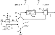
図1を参照すると、本発明は、石炭がガス化される、本発明による方法を実行する装置1を示す。先に示したように、ガス化される原料が、石炭、アスファルト、重油、石油コークス、バイオマス又は天然ガスなどの他の物質であることができるため、図1は例示のためのものである。
Referring to FIG. 1, the present invention shows an
図1によれば、調製された石炭送給ストリーム10は、酸素ストリーム14などのガス化剤の添加によって、ガス化炉12内でガス化される。酸素ストリーム14は、極低温精留ユニット16内における空気の極低温精留によって生成される。移動床ガス化炉などの一部のガス化炉では、蒸気ストリーム91(説明される)のような高圧蒸気も、ガス化炉内に注入される。
According to FIG. 1, the prepared
極低温精留ユニット16(「ASU」)は、空気ストリーム17を圧縮する圧縮器、並びに、二酸化炭素、水及び炭化水素などの高沸点汚染物質を除去する純化器からなる。戻りストリームが、空気の分留成分、すなわち、窒素及び酸素からなるのに対して、結果得られる純化され圧縮されたストリームは、その後、主熱交換器内で冷却される。酸素は、酸素ストリーム14として放出され、窒素は、窒素ストリーム18として放出される。必要ならば、酸素ストリーム14は、ガス化炉12へ注入するために適した圧力まで圧縮され得る。
The cryogenic rectification unit 16 (“ASU”) consists of a compressor that compresses the
典型的な極低温精留ユニット16では、一般に、凝縮器−リボイラーによって低圧カラムに動作可能に連結される高圧カラムを有する2重蒸留カラムにおいて、空気は、主熱交換器内で精留に適した温度まで冷却される。高圧カラムは、通常、約5バール絶対圧で動作して、窒素リッチのオーバヘッド及び酸素リッチのカラム底液を生成することになる。酸素リッチのカラム底液はさらに、約1.2バール絶対圧で一般に動作する低圧カラム内で精製される。低圧カラムのカラム底液は、酸素が豊富である。高圧カラム内で生成される窒素リッチ塔オーバヘッドを凝縮するのに対して、酸素が気化される。高圧カラムの結果得られる凝縮物は、弁膨張され、低圧カラムに還流するのに使用される。
In a typical
酸素ストリーム14を発生させる他の代替法が可能である。たとえば、酸素輸送膜反応器であって、当技術分野で知られている方法で酸素を分離するために、圧縮空気が、燃焼器内で部分的に燃焼され、酸素輸送膜反応器内に導入され得る、酸素輸送膜反応器である。
Other alternatives for generating the
ガス化炉12は、多くの商業的に入手可能なガス化技術のいずれをも組込む。たとえば、向流「固定(fixed)」(又は移動)床タイプのガス化炉では、下方に流れる炭素質燃料床は、移動床の底部に入る、蒸気と酸素によって生成されるガス化製品に接触する。ガス化製品は、炭素質床に対して向流構成で流れる。スラグ又は灰13は、全てのガス化炉で除去されることになる。たとえば、向流固定床ガス化炉では、参照数字13は、除去用のスラグを指定するであろう。流動床ガス化炉では、燃料粒子は、床の底部での又は底部の近くでの酸素と蒸気の注入の結果として液状化される。噴流床ガス化炉では、粉砕石炭などの乾燥した粉砕固体又は燃料スラリーは、並流の流れにおいて酸素によってガス化される。
The
ガス化炉12内で、石炭と酸素を含む、知られている反応が、水素、一酸化炭素、メタン、二酸化炭素、蒸気、硫黄化合物及び少量の大分子炭化水素を含有する合成ガスストリーム20を生成する。合成ガスストリーム20の温度は、使用されるガス化炉のタイプに依存することになる。ガス化炉12の噴流床ガス化炉では、合成ガスは、約1600°F(871.1℃)と約3500°F(1927℃)との間の温度でプロセスのガス化セクションを出る。しかし、本発明による集積化において他のタイプのガス化炉が使用され得ることが留意され、したがって、他のタイプのガス化炉では、合成ガスストリームが他の温度範囲で生成されることになることを述べる価値がある。たとえば、固定床ガス化炉では、合成ガスは、約900°F(482.2℃)と約1000°F(537.8℃)との間の温度で生成されることになる。
Within the
合成ガスストリーム20からの粒子除去は、サイクロン又はキャンドルフィルタ22を含む、知られている技術によって実行され得る。キャンドルフィルタ22は、合成ガスストリーム20からこうした粒状物質を除去するのに使用されるセラミック又は金属のキャンドルフィルタであり得る。キャンドルフィルタ22は、いずれにしても好ましくは、約700°F(371.1℃)、より好ましくは、1000°F(537.8℃)以上で動作すべきである。ろ過は、膨張器をエロージョンから保護するために一般に存在する点でオプションであることが留意される。一部のガス化炉では、ストリームは、炭素変換を改善するために、ガス化炉のフロントエンドに対して再利用される。
Particle removal from the
得られるろ過された合成ガスストリーム24は、酸素輸送膜ボイラー26にその後送出される合成ガスを含有する。好ましい特定の酸素輸送膜ボイラーは存在しないが、こうしたいずれのデバイスでも、ろ過された合成ガスストリーム24は、上述したような、混合伝導体又は2相伝導体であり得るセラミック材料で作られた複数の管を備え得る酸素輸送膜システム28内に導入される。酸素輸送膜システム28は、管以外の形態の酸素輸送膜エレメント、たとえば、当技術分野で同様に知られている平面エレメントを使用し得ることが理解される。酸素含有ガス、たとえば、空気は、ブロワ32の使用によって空気ストリーム30として管内に導入される。空気ストリーム30は、酸素輸送膜管内に導入される前に廃熱回収熱交換器34によって予熱される。酸素イオンは、膜に浸透し、ろ過された合成ガスストリーム24と即座に結合して、ろ過された合成ガスストリーム24の燃焼を維持する。酸素欠乏保持液は、保持液ストリーム35として、熱の回収及び放出のために廃熱回収熱交換器34を通して流される。
The resulting filtered
例示された酸素輸送膜ボイラー26では、ろ過された合成ガスストリーム24の燃焼は、酸素輸送膜システム28内での酸素分離用の駆動力を提供する。したがって、空気ストリーム30は、それほど圧縮されない。しかし、本発明による、酸素含有ガスについて圧縮を実際に利用する酸素輸送膜ボイラーを集積化することが可能であるが、こうした集積化は、こうした圧縮において必要とされる電力ペナルティのために好ましくない。
In the illustrated oxygen
好ましくは、OTM管の表面温度は、酸素輸送膜ボイラー26全体にわたって約1600°F(871.1℃)と約2000°F(1093℃)との間に維持される。煙道ガスストリーム36は、好ましくは約1600°F(871.1℃)と約2000°F(1093℃)との間の温度で酸素輸送膜ボイラー26から放出される。煙道ガスストリーム36は、少量の窒素、アルゴン及び二酸化硫黄並びにおそらくは残留酸素と共に、主に水及び二酸化炭素からなる。
Preferably, the surface temperature of the OTM tube is maintained between about 1600 ° F. (871.1 ° C.) and about 2000 ° F. (1093 ° C.) throughout the oxygen
酸素輸送膜ボイラー26内で起こる燃焼によって発生する熱は、全体が参照数字38で示される熱交換ネットワークによって回収され、熱交換ネットワークでは、発電機42を駆動するために適用できる動力を発生する蒸気タービンシステムを組込む、全体がブロック40で示される蒸気サイクル(「ST」)において、蒸気が生成され利用される。本発明に関連して使用する可能性がある多くの蒸気サイクルが存在し、実際に、蒸気サイクルの設計は、こうした設計を作り出すことが特に可能なコンピュータプログラムによって実行されることが多い日常の仕事である。説明されるように、極超臨界蒸気サイクルが好ましい。しかし、亜臨界及び超臨界蒸気サイクルも可能である。さらに、酸素輸送膜ボイラー26について考えられる多くの設計が存在する。こうしたことを述べたが、例として、酸素輸送膜ボイラー26及び関連する蒸気サイクル40に関連して使用され得る、適した設計のより詳細な説明が図2に示される。
The heat generated by the combustion that occurs in the oxygen
ここで図2を特に参照すると、酸素輸送膜ボイラー26は、以降で説明されることになる方法で改良された商業的に入手可能な従来のユニットに基づく。酸素輸送膜ボイラー26は、一般に、輻射熱移動が支配的である輻射セクション44及び熱移動が対流熱移動によって達成される対流セクション46からなる。酸素輸送膜ボイラー26は、蒸気サイクル40と集積化される。
Referring now specifically to FIG. 2, the oxygen
輻射セクション44は、酸素輸送膜ボイラー26の酸素輸送膜システム28を形成する酸素輸送膜管50を設けることによって変更される。酸素輸送膜管50は、空気ストリーム30を受取るために並列に接続され、蒸気を起こすため、また、蒸気サイクル40のために、熱交換ネットワーク38の一部を形成する一連の蒸気管52、54、56及び58と交互に並ぶ。例示される実施形態では、蒸気管52、54、56及び58は直列である。しかし、実際には、蒸気管は、輻射セクション44が均一な温度を有する点で輻射セクション44内のどこにでも配置され得る。特に示さないが、蒸気管52、54、56及び58はそれぞれ、大きな交互アレイの一部であることになり、アレイの全ての蒸気管、たとえば、蒸気管52は並列に接続されることになる。さらに、同様に示さないが、蒸気管52内で生成される飽和蒸気は、蒸気管54内に導入される前に蒸気ドラム内に収集され得る。
The
蒸気サイクル40に関して、極超臨界蒸気サイクルが好ましく、本明細書で使用されるように、また、特許請求の範囲では、少なくとも約1000°F(537.8℃)の温度及び少なくとも4000psiaの圧力の蒸気を使用するサイクルを意味する。蒸気サイクル40の以下の説明は、以下に説明する例1及び例2に適用可能な温度及び圧力を利用する。
With respect to the
蒸気サイクル40によれば、ボイラー給水ストリーム60は、ポンプ62によって圧送されることによって加圧され、予熱器64、66、68及び70並びに対流セクション46内の熱交換器72及び74内で予熱され、約650°F(343.3℃)の温度及び約4366psiaの圧力になり、4366psiaは、配管損失が小さい加圧によって与えられた。説明される熱交換器72、74及び109並びに蒸気管52、54、56及び58は、酸素輸送膜ボイラー26の熱交換ネットワーク38を形成することが留意される。
According to the
ボイラー給水ストリーム60は、その後、蒸気発生器として働く蒸気管52に入り、次に、発生した蒸気を過熱する蒸気管54に入って、約1080°F(582.2℃)の温度及び約4050psiaの圧力の蒸気ストリーム76が生成される。蒸気ストリーム76は、次に、高圧蒸気タービン78(「HPT」)内に導入され、膨張して1226psiaになる。膨張ストリームの約2725klb/hr(ストリーム76の約90%を構成する)は、ストリーム80として、再加熱器として役立つ蒸気管56を通して流され、ストリーム80は、約1111°F(599.4℃)の温度に再加熱されて、約1170psiaの圧力を有するストリーム82が生成される。残りの部分84は、予熱器68内に導入される。
The
再加熱されストリーム82は、次に、主中間圧タービン86(「PIPT」)内に導入されて、膨張して、約505psia及び約822°F(438.9℃)の温度になる。このストリームの約2328klb/hr(ストリーム80の約85%を構成する)は、ストリーム88として、第2再加熱器として役立つ蒸気管58内に導入されて、約1111°F(599.4℃)の温度を有する再加熱されたストリーム90が生成される。膨張した蒸気の残りは、ストリーム92として予熱器64内に導入される。
The reheated
再加熱されたストリーム90は、次に、中間圧蒸気タービン94(「IPT」)内に導入される。蒸気96は、次に、低圧タービン98(「LPT」)内で膨張して、約0.75psiaの圧力になる。得られるストリーム100は、次に、凝縮器102に流され、次に、ポンプ104によって一連の低圧ボイラー−給水加熱器106、108、109、110及び112に圧送されて、中間圧蒸気タービン94及び低圧タービン98から取得される抽出蒸気ストリーム114、116、118及び120を使用して約210°F(98.89℃)に加熱される。抽出ストリームは全て、結合され、ポンプ105によって所定圧で圧送され、ストリーム100と結合される。結果得られる加熱された給水ストリーム122は、ストリーム128及び中間圧蒸気タービン94から抽出されたストリーム130と共に、脱気装置126内で給水ストリーム124と混合され、水から揮発性ガスを取除くのに使用される。ストリーム128は、ストリーム92、ストリーム84及び主中間圧蒸気タービン86から抽出されるストリーム132で構成さる。脱気装置126からのストリーム60は、ポンプ62によって約4452psiaの圧力で圧送される。
The reheated
再び図1を参照すると、煙道ガスストリーム36は、次に、水−クーラ134内で約160°F(71.11℃)と約300°F(148.9℃)との間の温度に最初に冷却されることによって純化される。冷却されたストリーム136は、次に、当技術分野でよく知られており、また、二酸化硫黄の約98容積%超を除去することが可能な煙道ガス脱硫スクラバユニット138に送出される。煙道ガス脱硫スクラバユニット138は、種々の製造業者、たとえば、Babcock & Wilcox Company,20 S.Van Buren Avenue Barberton,OH,U.S.A 44203−0351から得られ得る、知られているシステムである。通常、煙道ガス脱硫スクラバユニット138は、3つの部分を備えることになる。すなわち、第1の部分は、ライムストーンが受取られ、貯蔵され、ボールミルで研磨されて、水性スラリーを調製するライムストーンハンドリング及び試薬調製である。第2の部分は、示す実施形態では、スプレイ塔カラム内で向流モードの冷却ストリーム136であることになる煙道ガスと、ライムストーンスラリーが接触するようになるスクラバである。この後に、煙道ガス脱硫吸収器からのブリードスラリーが脱水され、石膏が分離され貯蔵される副産物脱水が続く。結果得られる部分的に純化された煙道ガスストリーム140は、ある程度の残留アルゴン及び窒素、酸素並びに微量の二酸化硫黄と共に、主に二酸化炭素及び約10〜15モル%の水からなる。
Referring again to FIG. 1, the
部分的に純化された煙道ガスストリーム140は、次に、基底負荷圧縮器142内で約300psiaと約500psiaとの間の圧力に圧縮され、次に、水分を除去するために、乾燥ユニット148内で乾燥される。乾燥ユニットは、天然ガスを乾燥するのに通常使用される、知られているシステムであるグリコールシステムである。好ましくは、示さないが、部分的に純化された煙道ガスストリーム140は、こうした圧縮の前に、最初に約110°F(43.33℃)に冷却され、圧縮エネルギーを保存するために、凝縮物が除去される。基底負荷圧縮器142は、一般に、さらなる水を除去するために、ノックプットドラムを有する多段中間冷却圧縮システムであることも理解される。グリコールシステムは、NATCO Group Inc.2950 North Loop West,Suite 750 Houston,TX 77092を含む種々の製造元から得られ得る。典型的なグリコールシステムでは、圧縮後の部分的に純化された煙道ガスストリーム140は、吸収カラムのグリコール溶液内で向流で接触する。乾燥したガスは、吸収カラムの頂部を出る。吸収された水を含有するグリコール溶液は、接続された蒸留カラムに送出される。熱は、水を分離するために供給され、再生されたグリコール溶液は、ポンプを使用して吸収カラムに戻るように循環される。熱交換器を使用して、2つのカラム間を流れるグリコール溶液間で熱を交換する。水の除去は、パイプラインを腐食する可能性がある二酸化炭素製品内での炭酸の形成を防止する。通常、水位は、この目的のために、容積で約600ppm未満に減少されるべきである。
The partially purified
さらに、水含量を減少させることは、大気温度以下の純化プロセスなどの下流処理で使用されるときの凍結を防止することになる。示さないが、こうした目的のための乾燥器は、分子篩を使用する吸収に基づくことができる。こうした場合、乾燥器は、複数床分子篩乾燥器システムを備えることができ、床の半分は乾燥されるようにフィードを処理し、他の半分は再生を受ける。製品ガスの製品部分は、再生ガスとして使用され、再生ガスは、加熱器によって約450°F(232.2℃)に加熱されて、床から水分を除去する。床に水分が無くなった後、大気温度に近い再生ガスは、床を通って流されて、床を冷却する。再生ガスは、次に、こうした目的に利用される最後のステージの上流の適切な地点において、基底負荷二酸化炭素圧縮器142に対して再利用され得る。
Furthermore, reducing the water content will prevent freezing when used in downstream processes such as purification processes below ambient temperature. Although not shown, dryers for these purposes can be based on absorption using molecular sieves. In such cases, the dryer can be equipped with a multi-bed molecular sieve dryer system, where the feed is processed such that half of the bed is dried and the other half undergoes regeneration. The product portion of the product gas is used as regeneration gas, which is heated to about 450 ° F. (232.2 ° C.) by a heater to remove moisture from the floor. After the floor is dehydrated, regenerative gas close to ambient temperature is flowed through the floor to cool the floor. The regeneration gas can then be recycled to the base load
乾燥ユニット148からの乾燥ストリーム150は、次に、パイプラインに対して流され得る製品ストリーム154を生成するため、或いは、石油増進回収又は隔離のためにブースター圧縮器152に流される。ブースター圧縮器152は、多段中間冷却機である。製品ストリーム154は、好ましくは、少なくとも約90容積%の二酸化炭素含量を有し、例に示すように、二酸化炭素含量は、約92容積%又は約95容積%であり得る。
The
図3を参照すると、酸素輸送膜部分酸化反応器160を利用する別の実施形態が示される。この機構は、他のタイプのガス化炉に比べて少ない酸素を利用する移動床ガス化炉において石炭がガス化される場合に特定の適用性を有する。こうした実施形態では、合成ガスストリーム20は、900°F(482.2℃)と約1000°F(537.8℃)との間の温度で移動床ガス化炉12’によって生成され、タール及び石油などの揮発性物質を含有する。蒸気は、また、こうしたガス化炉において利用され、図2に示すように、中間圧蒸気タービン94の中間ステージ又はおそらくは他の図示しない供給源から抽出されるストリーム91によって得られる。部分酸化反応器160は、合成ガスを部分酸化して、その温度を、約1600°F(871.1℃)と約1800°F(982.2℃)との間まで上げ、それにより、酸化して水素、一酸化炭素、メタン及び二酸化炭素になるタール、石油及びフェノールなどの揮発性物質を除去する。部分酸化反応器160は、通常、管状形態の混合伝導体である1つ又は複数の酸素輸送膜エレメントを使用する。約1800°F(982.2℃)にて、部分酸化反応は、触媒が無い状態で進行することになる。この点で、合成ガスストリーム20は、しばしば、知られている触媒毒である硫黄を含有することになり、触媒反応器が使用される場合、上流の処理又は耐硫黄性触媒が必要とされるであろう。部分酸化反応器の典型的な例は、よく知られており、米国特許第5,820,654号、第5,820,655号及び第6,139,810号に示される。
Referring to FIG. 3, another embodiment utilizing an oxygen transport membrane
こうした実施形態では、図3に示すように、空気ストリーム30は、第1及び第2の副酸素含有ストリーム162及び164に分割される。第1副酸素含有ストリーム162は、酸素輸送膜ボイラー26に送給される。第2副酸素含有ストリーム164は、部分酸化反応器160の酸素輸送膜エレメントの内部に供給される。ろ過された合成ガスストリーム24は、こうした反応器のシェルの外側に供給され、酸素イオンは、揮発性成分と反応して、上述した反応製品を生成する。或いは、ユニット32及び34と類似のブロワ及び熱交換器と一緒の別個の空気供給が使用されて、ユニット26及び160に対する酸化体を供給し得る。
In such an embodiment, as shown in FIG. 3, the
揮発性成分が酸素輸送膜部分酸化反応器160内で反応した後の、得られた合成ガスストリーム166は、約300psiaと約1200psiaとの間の圧力を有する。合成ガスストリームは、次に、さらなる電力を発生する発電機170に連結された膨張器168内で膨張する。装置1についての約60%と約80%との間の総酸素要求は、通常、酸素輸送膜部分酸化反応器160及び酸素輸送膜ボイラー26内に収容される酸素輸送膜によって供給されることになる。残りは、極低温空気分離ユニット16によって、ガス化炉12’に供給される。保持液ストリーム172は、保持液ストリーム35に合流し、結合ストリームは、熱回収熱交換器34に送給される。
The resulting
図4を手短に参照すると、噴流床又は流動床タイプのガス化炉12”を利用する図3の代替の実施形態が示される。こうしたガス化炉によって生成される合成ガスストリーム20’の温度は約1800°F(982.2℃)であるため、非常に熱い給水ストリーム155から蒸気ストリーム158を生成するために、高圧蒸気ボイラー156が設けられる。蒸気ストリーム158は、酸素輸送膜ボイラー26内に位置し、且つ、図2により詳細に示される蒸気管54に入る蒸気と結合され得る。ボイラー156は、ストリーム20’の温度を減少させて、約1000°F(537.8℃)未満の動作温度に現在のところ制限される高温フィルタの使用を容易にする。これらのフィルタが使用されて、先に述べたホットガス膨張器内のエロージョンを最小にする。
Referring briefly to FIG. 4, there is shown an alternative embodiment of FIG. 3 utilizing a spouted or fluidized
図5を参照すると、部分酸化ステージ及び膨張ステージが示され、そこで、ろ過された合成ガスストリーム24は、第1部分酸化反応器180によって作られる第1部分酸化ステージ内に導入され、それに続いて、さらなる電気を発生する発電機184に連結した膨張器182によって設けられる膨張ステージ内の膨張によって導入される。その後、膨張器182後の処理されたろ過済み合成ガスストリーム24は、次に、第2部分酸化反応器186によって設けられる第2部分酸化ステージ内に導入され、それに続いて、さらなる電力を発生するさらなる発電機190に連結した第2膨張器188によって設けられる第2膨張ステージ内に導入される。こうした実施形態では、第2副酸素含有ストリーム164は、第1部分酸化反応器180及び第2部分酸化反応器186内に送給される部分164a及び164bに分割される。得られる酸素欠乏保持液ストリーム172a及び172bは、結合されて、結合ストリーム172cを生成し、結合ストリーム172cは、さらに、保持液ストリーム35と結合され、熱回収熱交換器34を通して流される。やはり、先に説明したように、独立した空気供給システムも可能である。
Referring to FIG. 5, a partial oxidation stage and an expansion stage are shown, where the filtered
図6を参照すると、ボイラー26の酸素輸送膜システム28内で燃焼が終了しない実施形態が示される。通常、完全燃焼に必要であることになる、酸素輸送に要求される面積は非常に大きいであろう。過剰のコストを回避するために、燃焼は、合成ガスストリーム20内に含有される燃料種の約80%と約90%との間の程度だけで終了してもよい。こうした状況では、煙道ガスストリーム36は、水素及び一酸化炭素などの少量の燃料種を含有することになる。二酸化炭素ストリームは、その後さらに、極低温蒸留を組込む純化ユニット200内で純化され得る。外部冷却による蒸留プロセスを含む代替の純化方法を使用して、純化ユニット200を形成してもよい。よく知られている純化プロセスは、米国特許第5,927,103号、第6,035,662号及び第6,070,471号に示される。
Referring to FIG. 6, an embodiment is shown in which combustion does not end within the oxygen
図7を参照すると、部分的に純化された煙道ガスストリーム140を純化する純化ユニット200の特定の実施形態が示される。部分的に純化された煙道ガスストリーム140は、圧縮器202内で圧縮され、約150psiaと約1000psiaとの間の圧力になる。回収され得る二酸化炭素の量は、コールドボックスに供給される送給圧の関数である。理解され得るように、二酸化炭素回収は、この圧力を増すことによって増加し得る。しかし、こうした圧力増加は、生産コストの増加をもたらすことになる。水冷式チラー204内で冷却された後、部分的に純化された煙道ガスストリーム140は、次に、水冷式チラー204内で冷却されたために部分的に純化された煙道ガスストリーム140内に凝縮された水を分離するために相分離器205内に導入される。
Referring to FIG. 7, a specific embodiment of a
部分的に純化された煙道ガスストリーム140は、次に、乾燥器206内に導入される。乾燥器206は、好ましくは、水分、及び、部分的に純化された煙道ガスストリーム140より高温で沸騰することになる重質炭化水素などの他の不純物を吸収するために、ある相から出て動作する分子篩吸収剤の床を収容し得る吸収システムである。分子篩吸収剤の床は、ある相から出て動作するため、1つの床がこうした高沸点不純物を吸収するにつれて、他の床は再生される。また2より大きい番号の付いた偶数の床が、大きな流れに使用され得、床の半分は吸収を実施し、一方、床の他の半分は再生を受ける。床は、吸収された成分を脱着するために、その圧力を下げ、且つ/又は、その温度を上げ、次に、吸収成分が少ないストリームで床をパージングすることによって再生される。温度変動を使用するシステムでは、床は、吸収成分が少ないストリームを加熱し、次に、再生される床内にストリームを導入して、脱着を引き起こし、また、脱着された成分を除去することによって再生される。これらのシステムは多岐に亘るが、当技術分野でよく知られている同システムの多くの例が存在する。この点で、蒸留技術でよく知られている可逆熱交換器の使用などによる非吸収ベースシステムが可能である。
The partially purified
結果得られる乾燥した送給ストリーム208(圧縮器202によって圧縮され、乾燥された後の、部分的に純化された煙道ガスストリーム140からなる)は、次に、ストリーム208が部分的に冷却される主熱交換器210内に導入され、次に、ストリッピングカラム214内で沸騰を生成するか、又は、上行蒸気相を始動するのに役立つリボイラー212内に導入される。乾燥した送給ストリーム208は、次に、ストリーム208が完全に冷却される主熱交換器210内に再び導入されて、乾燥した送給ストリーム208を少なくとも部分的に液化する。乾燥した送給ストリーム208は、次に、膨張弁216を通してストリッピングカラム214内に導入されて、ストリッピングカラム214内で下行液相を始動する。
The resulting dry feed stream 208 (comprised of the partially purified
当技術分野でよく知られているように、ストリッピングカラム214は、好ましくは、規則充填物であって、充填物を通して上に流れる上行蒸気相を、液相の下行液膜と接触させる、規則充填物を有する。篩トレイなどの当技術分野で知られている他の蒸気−液体接触エレメントが使用され得る。接触の結果として、下行液相は、二酸化炭素が益々豊富になり、揮発性の低い成分及び上行蒸気相は、二酸化炭素より高い揮発性を有する不純物が益々豊富になる。ストリッピングカラム214内で、ろ過された合成ガスストリーム24の残りの未燃焼成分、すなわち、水素、一酸化炭素及びメタン、並びに、燃焼ゾーン内への空気流入によって生じる可能性がある任意の不活性成分、すなわち、窒素及びアルゴン(全て、二酸化炭素より揮発性が高い)は、下行液から取除かれて、二酸化炭素リーンカラムオーバヘッド及び二酸化炭素リッチ液体カラム底液を生成する。
As is well known in the art, the stripping
二酸化炭素リーンカラムオーバヘッドからなるカラムオーバヘッドストリーム218は、ストリッピングカラム214から抽出され、次に、補助熱交換器220内に導入され、その結果、二酸化炭素オーバヘッドストリーム218は、少なくとも部分的に液化される。二酸化炭素オーバヘッドストリーム218は、次に、相分離器224内に導入されて、二酸化炭素欠乏蒸気ストリーム226及び二酸化炭素リッチ液体ストリーム228を生成する。二酸化炭素リッチ液体ストリーム228は、膨張弁230内で膨張し、次に、二酸化炭素欠乏蒸気ストリーム226と一緒に、補助熱交換器220内に流される。膨張弁230は、二酸化炭素オーバヘッドストリーム218の部分的液化のための冷却を提供する。
A
二酸化炭素欠乏蒸気ストリーム226は、主熱交換器210内に流され、次に、再利用され、ろ過された合成ガスストリーム24と結合して、酸素輸送膜部分酸化反応器160へ合成ガス送給ストリーム24’を供給する。当業者によって理解されることになるように、使用されるガス化炉が、二酸化炭素欠乏蒸気ストリーム226より高圧で動作する場合、再利用を達成するために、再利用圧縮器が設けられなければならないことになる。少量のストリーム226は、燃料ストリームとしてプロセスからパージングされて、ループ内での窒素及びアルゴンなどの不活性ガスの蓄積が回避され得る。パージガスは、一酸化炭素、メタン又は他の排気物を管理するために、焼却又は触媒酸化又は他の処理を必要とする場合がある。
The carbon dioxide-
主熱交換器210を通して流された後の二酸化炭素リッチ液体ストリーム228は、気化され、したがって、乾燥器206を再生するのに使用され得る。たとえば、こうしたストリームは、加熱され、次に、再生のために吸収床内に導入され、その後、圧縮器202の適切なステージ内に再利用ストリーム236として再導入されて、二酸化炭素回収を高める。
The carbon dioxide rich
二酸化炭素リッチ液体カラム底液からなる、液体としての二酸化炭素製品ストリーム240は、ストリッピングカラム214から抽出され得る。二酸化炭素製品ストリームは、次に、膨張弁内で膨張して、プロセス用の冷却を生成し得る。有利には、二酸化炭素製品ストリーム240は、副ストリーム242及び244に分割され、少なくとも副ストリーム244は、膨張弁246の使用によって膨張して低圧になり、任意選択で、ストリーム242及び244は共に、それぞれ、膨張弁246及び248の使用によって同時に膨張して低圧及び高圧になる。副ストリーム242及び244は共に、次に、主熱交換器210内で気化される。得られる低圧副ストリーム242は、製品圧縮器250の入口に導入される。低圧副ストリーム244は、製品圧縮器250の中間ステージ内に導入される。製品圧縮器250は、段間冷却を有する多段圧縮器であり得る。示さないが、二酸化炭素製品の一部は、二酸化炭素製品ストリームから液体として取得され得ることが留意される。
A carbon
図8を参照すると、図6の別の変形は、燃料の燃焼を終了させるために、酸素輸送膜ボイラー26の輻射セクション44内に補助酸素含有ストリーム254を注入することである。補助酸素ストリーム254は、捕捉される二酸化炭素内での窒素の蓄積を防止するために、少なくとも約40%酸素を含有する酸素含有ストリームである。こうしたプロセスの欠点は、不活性ガスが煙道ガスストリーム36内に導入され、それにより、二酸化炭素の純度が低下することになることである。こうした実施形態では、成分の特性に応じて単に処理されるか、又は、排気されることになる、部分的に純化された煙道ガスストリームの揮発性の高い成分を含有するストリーム226’が生成され得る。ストリーム226’はまた、酸素を含有し得る。したがって、示さないが、触媒酸化は、酸素輸送膜ボイラー26の輻射セクション又は対流セクションの終わりに組込まれ得る。これはまた、完全燃焼を達成するのに必要とされる酸素量を減少させる。この点で、本発明の任意の実施形態において過剰の酸素が存在する程度まで、こうした触媒酸化が、純化と一緒に組込まれ得る。
Referring to FIG. 8, another variation of FIG. 6 is to inject a supplemental oxygen-containing
図3、4及び5に示す装置は、こうした示される実施形態の予測性能を評価するために、コンピュータプログラムを使用してモデル化された。「炭素捕捉及び隔離システム解析指針(Carbon Capture and Sequestration Systems Analysis Guidelines)」米国エネルギー省(U.S.Department of Energy)、化石燃料局(Office of Fossil Energy)、国立エネルギー技術研究所(National Energy Technology Laboratory)、2005年4月に述べられた指針は、EPRI報告書、Holt,N.著「CO2除去を有する化石燃料発電プラントについてのコスト及び性能評価の更新(Updated Cost and Performance Estimates for Fossil Fuel Power Plants with CO2 Removal)」EPRI Report to DOE−NETL No.1004483,12月(2002年)、U.S.DOE/NETL,Pittsburgh及びHolt,N.著「CO2除去を有する革新的な化石燃料発電プラントの評価(Evaluation of Innovative Fossil Fuel Power Plants with CO2 Removal)」EPRI Report to DOE−NETL No.1000316、12月(2000年)、U.S.DOE/NETL,Pittsburgh,PAに含まれる仮定と一緒に使用された。表1に列挙する特定の仮定が、例において使用され、また、これらの指針と異なる場合がある。
The apparatus shown in FIGS. 3, 4 and 5 was modeled using a computer program to evaluate the predictive performance of such illustrated embodiments. “Carbon Capture and Sequestration Systems Analysis Guidelines,” US Department of Energy, National Institute of Energy, National Institute of Energy, National Institute of Energy. (Laboratory), April 2005, the guidelines described in the EPRI report, Holt, N .; Al., "An update of the cost and performance evaluation of the fossil fuel power plants with CO 2 removal (Updated Cost and Performance Estimates for Fossil Fuel Power Plants with
表4、5及び6は、それぞれ、図3、5及び4に示すプロセスについての重要なストリームを提供する。3つの場合についての性能比較は、表7に要約される。

酸素輸送膜ボイラー26内の酸素輸送膜システム28の設計に関して、所与のサイズのボイラーについて、必要とされることになる図2の酸素輸送膜管50などの酸素輸送膜管の表面積及び数は、管の単位面積当たりの酸素フラックス並びに単一管の長さ及び直径に依存する。例を挙げると、約500MWeの正味の電力を生成する酸素輸送膜ボイラー26を設計するために、石炭の量が計算される。500MWeの場合、Illinois No.6石炭の4838tpdが必要とされることになる。こうして、ガス化炉の動作をシミュレートすることになる、いくつかの知られているプログラムのうちの任意のプログラムを使用して、生成されることになる合成ガスの量も、必要とされることになる酸素の量と共に計算され得る。ガス化炉から生成される合成ガスの量がわかると、完全燃焼に必要とされる酸素の量に関する計算が行われ得る。送給空気内の酸素の70%だけが酸素輸送膜管を通して移動することになると仮定し、またさらに、煙道ガス内に約0.2から約0.4モルパーセントの酸素が残っていると仮定する。このことから、必要とされることになる、実際の酸素の量及び送給空気の量も計算され得る。酸素輸送膜管を通して移動するのに必要とされる酸素の量がわかると、酸素輸送膜管の必要とされる表面積が計算され得る。ただし、酸素輸送膜管を通る酸素フラックスの量がわかっている場合に限る。例示のための仮定される酸素フラックスは、約20scf/ft2/hrである。もちろん、正確な酸素フラックスは、膜材料の性能に依存するであろう。そのため、酸素フラックスが低いシステムの場合、以下に述べる例示的な結果を達成するために、より大きな膜面積が必要とされることになる。これは、効率を減少させないが、投資コストを増加させるであろう。このフラックスを使用して、表面積要求が計算され得、こうした計算のサンプルが以下の表2に示される。
酸素輸送膜管の実際の数は、管の外径及び長さに依存することになる。2つの異なる管の長さに基づいて、3の例について必要とされる管の数は、表3に与えられる。
表7から明らかであるように、図5の実施形態は、最も大きな正味電力を供給し、同様に最も効率的であった。 As is apparent from Table 7, the embodiment of FIG. 5 provided the greatest net power and was also most efficient.
本発明は、好ましい実施形態に対して述べられたが、当業者によって理解されることになるように、現在係属中の特許請求の範囲に述べられる本発明の精神及び範囲から逸脱することなく多数の変更及び省略が行われ得る。 Although the present invention has been described in terms of a preferred embodiment, it will be appreciated by those skilled in the art that numerous changes can be made without departing from the spirit and scope of the invention as set forth in the appended claims. Changes and omissions can be made.
Claims (13)
ガス化炉内で合成ガスストリームを発生させること、
熱及び煙道ガスを発生させるために前記合成ガスストリームを燃焼させることであって、前記合成ガスストリームは高温にある間に燃焼され、
前記煙道ガスは二酸化炭素を含有し、
前記合成ガスストリームの前記燃焼は、ボイラーに動作可能に連結される酸素輸送膜システム内で酸素含有ストリームから酸素を分離することによって維持されること、
前記熱をボイラー給水に間接的に伝達することによって前記ボイラー内で蒸気を生成すること、
前記酸素輸送膜ボイラーに動作可能に連結され、蒸気サイクルの蒸気タービンシステムによって前記蒸気からエネルギーを抽出し、前記蒸気タービンシステムに連結される発電機によって前記エネルギーを電力に変換すること、及び、
二酸化炭素リッチストリームを生成するために前記煙道ガスストリームを純化することを含み、
前記合成ガスストリームの揮発性内容物を酸化し、前記合成ガスストリームを加熱するために、前記合成ガスストリームを燃焼させる前に少なくとも1つの膨張ステージの膨張器内で前記合成ガスストリームを膨張させ、前記合成ガスストリームを膨張させる前に、少なくとも1つの部分酸化ステージ内で前記合成ガスストリームを部分酸化させることをさらに含み、前記膨張器は、別の発電機に連結されて、さらなる電力を発生し、前記部分酸化ステージは、前記合成ガスストリームの部分酸化を維持するために酸素を発生する酸素輸送膜反応器によって形成される、上記方法。 A method of generating power,
Generating a synthesis gas stream in the gasifier;
Combusting the syngas stream to generate heat and flue gas, wherein the syngas stream is combusted while at an elevated temperature;
The flue gas contains carbon dioxide,
The combustion of the syngas stream is maintained by separating oxygen from the oxygen-containing stream in an oxygen transport membrane system operably connected to the boiler;
Generating steam in the boiler by indirectly transferring the heat to the boiler feed water;
Operably coupled to the oxygen transport membrane boiler, extracting energy from the steam by a steam turbine system in a steam cycle, and converting the energy to electrical power by a generator coupled to the steam turbine system; and
Look including to purify the flue gas stream to produce a carbon dioxide rich stream,
Expanding the synthesis gas stream in an inflator of at least one expansion stage prior to burning the synthesis gas stream to oxidize the volatile contents of the synthesis gas stream and heat the synthesis gas stream; Prior to expanding the syngas stream, further comprising partially oxidizing the syngas stream in at least one partial oxidation stage, wherein the expander is coupled to another generator to generate additional power. The method, wherein the partial oxidation stage is formed by an oxygen transport membrane reactor that generates oxygen to maintain partial oxidation of the synthesis gas stream .
前記燃料種は、前記煙道ガスストリームから分離され、前記少なくとも1つの部分酸化ステージに対して再利用される請求項1に記載の方法。 The combustion of the syngas stream is incomplete resulting in the presence of fuel species in the flue gas stream;
The method of claim 1 , wherein the fuel species is separated from the flue gas stream and reused for the at least one partial oxidation stage.
前記煙道ガスストリームを冷却して、冷却済み煙道ガスストリームを生成し、
前記冷却済み煙道ガスストリームから二酸化硫黄を除去し、
前記煙道ガスストリームから前記二酸化硫黄を除去した後、前記煙道ガスストリームを圧縮し、次に、前記煙道ガスストリームを乾燥器内で乾燥させて、約90容積%もの純度を有する二酸化炭素含有ストリームを生成し、
前記二酸化炭素含有ストリームをさらに圧縮して、二酸化炭素製品ストリームを生成することによって純化される請求項1乃至3のいずれかに記載の方法。 The carbon dioxide is
Cooling the flue gas stream to produce a cooled flue gas stream;
Removing sulfur dioxide from the cooled flue gas stream;
After removing the sulfur dioxide from the flue gas stream, the flue gas stream is compressed and then the flue gas stream is dried in a dryer to have a carbon dioxide purity of about 90% by volume. Producing a containing stream,
4. A method according to any preceding claim, wherein the carbon dioxide containing stream is further compressed to produce a carbon dioxide product stream.
前記二酸化炭素は、
前記煙道ガスストリームを冷却して、冷却済み煙道ガスストリームを生成し、
前記冷却済み煙道ガスストリームから二酸化硫黄を除去し、
前記煙道ガスストリームから前記二酸化硫黄を除去した後、前記煙道ガスストリームを圧縮し、次に、前記煙道ガスストリームを乾燥器内で乾燥させて、約90容積%もの純度を有する二酸化炭素含有ストリームを生成し、
前記二酸化炭素含有ストリームをさらに圧縮して、二酸化炭素製品ストリームを生成することによって純化され、
前記燃料種は、乾燥された後で、且つ、さらに圧縮される前に前記煙道ガスストリームから分離され、前記少なくとも1つの部分酸化ステージに対して再利用される請求項3に記載の方法。 The combustion of the syngas stream is incomplete resulting in the presence of fuel species in the flue gas stream;
The carbon dioxide is
Cooling the flue gas stream to produce a cooled flue gas stream;
Removing sulfur dioxide from the cooled flue gas stream;
After removing the sulfur dioxide from the flue gas stream, the flue gas stream is compressed and then the flue gas stream is dried in a dryer to have a carbon dioxide purity of about 90% by volume. Producing a containing stream,
The carbon dioxide-containing stream is further compressed to produce a carbon dioxide product stream,
The method of claim 3 , wherein the fuel species is separated from the flue gas stream after being dried and before further compression and reused for the at least one partial oxidation stage.
前記合成ガスストリームは、加熱されたボイラー給水ストリームとの間接的熱交換によって冷却されて、蒸気ストリームを生成し、
前記蒸気ストリームは、前記ボイラー内で生成される蒸気と結合される請求項1に記載の方法。 The gasifier is a spouted bed gasifier;
The synthesis gas stream is cooled by indirect heat exchange with a heated boiler feed stream to produce a steam stream;
The method of claim 1 , wherein the steam stream is combined with steam generated in the boiler.
前記合成ガスストリームの前記燃焼は、酸素含有ストリームの添加によって完全にされる請求項1に記載の方法。 The combustion of the synthesis gas stream maintained by separating oxygen from the oxygen-containing stream in the oxygen transport membrane system is not complete,
The method of claim 1 , wherein the combustion of the synthesis gas stream is completed by the addition of an oxygen-containing stream.
Applications Claiming Priority (3)
| Application Number | Priority Date | Filing Date | Title |
|---|---|---|---|
| US11/639,459 US7856829B2 (en) | 2006-12-15 | 2006-12-15 | Electrical power generation method |
| US11/639,459 | 2006-12-15 | ||
| PCT/US2007/087735 WO2008076963A2 (en) | 2006-12-15 | 2007-12-17 | Electrical power generation method |
Publications (3)
| Publication Number | Publication Date |
|---|---|
| JP2010521944A JP2010521944A (en) | 2010-06-24 |
| JP2010521944A5 JP2010521944A5 (en) | 2011-02-03 |
| JP5302895B2 true JP5302895B2 (en) | 2013-10-02 |
Family
ID=39525489
Family Applications (1)
| Application Number | Title | Priority Date | Filing Date |
|---|---|---|---|
| JP2009541633A Expired - Fee Related JP5302895B2 (en) | 2006-12-15 | 2007-12-17 | Power generation method |
Country Status (10)
| Country | Link |
|---|---|
| US (2) | US7856829B2 (en) |
| EP (1) | EP2219762B1 (en) |
| JP (1) | JP5302895B2 (en) |
| KR (1) | KR101379110B1 (en) |
| CN (1) | CN102015072B (en) |
| AU (1) | AU2007333808B2 (en) |
| CA (1) | CA2672801C (en) |
| RU (1) | RU2439432C2 (en) |
| WO (1) | WO2008076963A2 (en) |
| ZA (1) | ZA200904110B (en) |
Families Citing this family (170)
| Publication number | Priority date | Publication date | Assignee | Title |
|---|---|---|---|---|
| DE10323774A1 (en) * | 2003-05-26 | 2004-12-16 | Khd Humboldt Wedag Ag | Process and plant for the thermal drying of a wet ground cement raw meal |
| RU2335642C1 (en) * | 2007-02-19 | 2008-10-10 | Олег Николаевич Фаворский | Electric power generator with high-temperature steam turbine |
| CN201031677Y (en) * | 2007-03-30 | 2008-03-05 | 辽河石油勘探局 | Boiler flue gas pressurization absorption CO2 liquify pouring well oil production device |
| US7874140B2 (en) * | 2007-06-08 | 2011-01-25 | Foster Wheeler North America Corp. | Method of and power plant for generating power by oxyfuel combustion |
| WO2009009891A1 (en) * | 2007-07-17 | 2009-01-22 | Plasco Energy Group Inc. | A gasifier comprising one or more fluid conduits |
| US8424515B1 (en) * | 2008-02-07 | 2013-04-23 | Paragon Space Development Corporation | Gas reconditioning systems |
| CN101981272B (en) | 2008-03-28 | 2014-06-11 | 埃克森美孚上游研究公司 | Low emission power generation and hydrocarbon recovery systems and methods |
| CN101981162B (en) | 2008-03-28 | 2014-07-02 | 埃克森美孚上游研究公司 | Low emission power generation and hydrocarbon recovery systems and methods |
| FR2929686A1 (en) * | 2008-04-07 | 2009-10-09 | Air Liquide | APPARATUS AND METHOD FOR OXYCOMBUSTION WITH CO2 CAPTURE. |
| US20090288447A1 (en) * | 2008-05-22 | 2009-11-26 | Alstom Technology Ltd | Operation of a frosting vessel of an anti-sublimation system |
| US20090301108A1 (en) * | 2008-06-05 | 2009-12-10 | Alstom Technology Ltd | Multi-refrigerant cooling system with provisions for adjustment of refrigerant composition |
| EA201170200A1 (en) * | 2008-07-16 | 2011-08-30 | Юнион Инджиниринг А/С | METHOD FOR CLEANING CARBON DIOXIDE WITH THE USE OF LIQUID CARBON DIOXIDE |
| US8163070B2 (en) * | 2008-08-01 | 2012-04-24 | Wolfgang Georg Hees | Method and system for extracting carbon dioxide by anti-sublimation at raised pressure |
| CN101324331B (en) * | 2008-08-01 | 2012-07-18 | 黄钟成 | Method for combustion by replacing oil with coal |
| US20100050687A1 (en) * | 2008-09-04 | 2010-03-04 | Alstom Technology Ltd | Liquefaction of gaseous carbon-dioxide remainders during anti-sublimation process |
| AU2009303735B2 (en) | 2008-10-14 | 2014-06-26 | Exxonmobil Upstream Research Company | Methods and systems for controlling the products of combustion |
| US20100107592A1 (en) * | 2008-11-04 | 2010-05-06 | General Electric Company | System and method for reducing corrosion in a gas turbine system |
| US20100199558A1 (en) * | 2009-02-10 | 2010-08-12 | Steele Raymond Douglas | System and method for operating power generation systems |
| DE102009014447A1 (en) * | 2009-03-23 | 2010-09-30 | Man Turbo Ag | Power plant for IGSC process |
| EP2414074A1 (en) * | 2009-03-30 | 2012-02-08 | Shell Internationale Research Maatschappij B.V. | Process for producing purified synthesis gas |
| CA2756306A1 (en) * | 2009-03-30 | 2010-10-07 | Shell Internationale Research Maatschappij B.V. | Process for producing a purified synthesis gas stream |
| BRPI1011619A2 (en) * | 2009-04-06 | 2016-03-22 | Rentech Inc | thermal conversion process, method for producing ft product liquids, and system for conditioning synthesis gas. |
| WO2010127288A1 (en) * | 2009-05-01 | 2010-11-04 | Services Petroliers Schlumberger | Methods and systems for optimizing carbon dioxide sequestration operations |
| US20100242352A1 (en) | 2009-06-09 | 2010-09-30 | Sundrop Fuels, Inc. | Systems and methods for reactor and receiver control of flux profile |
| US9663363B2 (en) | 2009-06-09 | 2017-05-30 | Sundrop Fuels, Inc. | Various methods and apparatuses for multi-stage synthesis gas generation |
| WO2011155962A1 (en) | 2010-06-08 | 2011-12-15 | Sundrop Fuels, Inc. | Various methods and apparatuses for an ultra-high heat flux chemical reactor |
| US8814961B2 (en) | 2009-06-09 | 2014-08-26 | Sundrop Fuels, Inc. | Various methods and apparatuses for a radiant-heat driven chemical reactor |
| US8495882B2 (en) * | 2009-08-10 | 2013-07-30 | General Electric Company | Syngas cleanup section with carbon capture and hydrogen-selective membrane |
| DE102009036973A1 (en) * | 2009-08-12 | 2011-02-17 | Uhde Gmbh | Method for supplying an entrained flow gasification reactor with carbonaceous fuels |
| US20110097260A1 (en) * | 2009-10-28 | 2011-04-28 | Air Liquide Process & Construction, Inc. | Hydrogen Recovery And Methane Production From Residual Fuels and Biomass |
| BR112012010294A2 (en) | 2009-11-12 | 2017-11-07 | Exxonmobil Upstream Res Co | integrated system and method for the recovery of low emission hydrocarbon with energy production |
| EP2335804B1 (en) * | 2009-12-04 | 2014-09-10 | Alstom Technology Ltd | A method and a device for cleaning a carbon dioxide rich flue gas |
| US20110162380A1 (en) * | 2010-01-04 | 2011-07-07 | General Electric Company | Method to increase net plant output of a derated igcc plant |
| US9644160B2 (en) * | 2010-06-03 | 2017-05-09 | Cornerstone Environmental Group, Llc | Integrated fuel production and electricity generation |
| BR112012031505A2 (en) | 2010-07-02 | 2016-11-01 | Exxonmobil Upstream Res Co | stoichiometric combustion of enriched air with exhaust gas recirculation |
| TWI554325B (en) | 2010-07-02 | 2016-10-21 | 艾克頌美孚上游研究公司 | Low emission power generation systems and methods |
| US9903271B2 (en) | 2010-07-02 | 2018-02-27 | Exxonmobil Upstream Research Company | Low emission triple-cycle power generation and CO2 separation systems and methods |
| AU2011271634B2 (en) | 2010-07-02 | 2016-01-28 | Exxonmobil Upstream Research Company | Stoichiometric combustion with exhaust gas recirculation and direct contact cooler |
| US20120137700A1 (en) * | 2010-12-07 | 2012-06-07 | Dennis John Werner | System for Producing Power Using Low Pressure Gasification of a Stock Fuel |
| US9561476B2 (en) | 2010-12-15 | 2017-02-07 | Praxair Technology, Inc. | Catalyst containing oxygen transport membrane |
| US20120222426A1 (en) * | 2011-03-04 | 2012-09-06 | Conocophillips Company | Integrated gas turbine, sagd boiler and carbon capture |
| TWI563166B (en) | 2011-03-22 | 2016-12-21 | Exxonmobil Upstream Res Co | Integrated generation systems and methods for generating power |
| TWI593872B (en) | 2011-03-22 | 2017-08-01 | 艾克頌美孚上游研究公司 | Integrated system and methods of generating power |
| TWI563165B (en) | 2011-03-22 | 2016-12-21 | Exxonmobil Upstream Res Co | Power generation system and method for generating power |
| TWI564474B (en) | 2011-03-22 | 2017-01-01 | 艾克頌美孚上游研究公司 | Integrated systems for controlling stoichiometric combustion in turbine systems and methods of generating power using the same |
| JP5738045B2 (en) * | 2011-04-06 | 2015-06-17 | 三菱重工業株式会社 | Carbon dioxide recovery system and method |
| DE102011002320B3 (en) * | 2011-04-28 | 2012-06-21 | Knauf Gips Kg | Method and device for generating electricity from hydrogen sulfide-containing exhaust gases |
| FI126249B (en) * | 2011-05-10 | 2016-08-31 | Aalto-Korkeakoulusäätiö | Combustion procedure and incinerator |
| US8349214B1 (en) * | 2011-07-08 | 2013-01-08 | Praxair Technology, Inc. | Synthesis gas method and apparatus |
| US8623241B2 (en) | 2011-07-08 | 2014-01-07 | Praxair Technology, Inc. | Oxygen transport membrane system and method for transferring heat to catalytic/process reactors |
| ES2411780B1 (en) * | 2011-11-09 | 2014-05-07 | Fundación Centro De Innovación Y Demostración Tecnológica | PROCEDURE FOR THE WATER COMBUSTION OF SYNTHESIS GAS TO GENERATE ELECTRICITY. |
| WO2013078185A1 (en) * | 2011-11-22 | 2013-05-30 | Enerjetik Llc | Method of making carbon dioxide |
| US9486735B2 (en) | 2011-12-15 | 2016-11-08 | Praxair Technology, Inc. | Composite oxygen transport membrane |
| EP2791082B1 (en) | 2011-12-15 | 2021-01-20 | Praxair Technology, Inc. | Method of producing composite oxygen transport membrane |
| US9810050B2 (en) | 2011-12-20 | 2017-11-07 | Exxonmobil Upstream Research Company | Enhanced coal-bed methane production |
| NO20111770A1 (en) * | 2011-12-21 | 2011-12-21 | Modi Vivendi As | System and method for offshore industrial activities with CO2 reinjection |
| CN102518489B (en) * | 2012-01-06 | 2016-08-03 | 新奥科技发展有限公司 | Electricity-generating method, the device generated electricity for gasified production of energy products and heat |
| WO2013117730A2 (en) * | 2012-02-10 | 2013-08-15 | Alstom Technology Ltd | Water/steam cycle and method for operating the same |
| EA028822B1 (en) * | 2012-02-11 | 2018-01-31 | Палмер Лэбс, Ллк | Partial oxidation reaction with closed cycle quench |
| US9295961B2 (en) | 2012-03-26 | 2016-03-29 | Sundrop Fuels, Inc. | Various methods and apparatuses for internally heated radiant tubes in a chemical reactor |
| US9353682B2 (en) | 2012-04-12 | 2016-05-31 | General Electric Company | Methods, systems and apparatus relating to combustion turbine power plants with exhaust gas recirculation |
| US9784185B2 (en) | 2012-04-26 | 2017-10-10 | General Electric Company | System and method for cooling a gas turbine with an exhaust gas provided by the gas turbine |
| US10273880B2 (en) | 2012-04-26 | 2019-04-30 | General Electric Company | System and method of recirculating exhaust gas for use in a plurality of flow paths in a gas turbine engine |
| KR101467035B1 (en) * | 2012-07-19 | 2014-12-01 | 한국기계연구원 | The high efficiency pure oxygen combustion system using the ion transport membrane and turbocharger |
| US20140020557A1 (en) * | 2012-07-20 | 2014-01-23 | Uop Llc | Methods and apparatuses for generating nitrogen |
| CN102796561B (en) * | 2012-08-09 | 2014-04-30 | 武汉凯迪工程技术研究总院有限公司 | Anaerobic gasification method and device for biomass fuels by carbon dioxide circulation |
| WO2014043552A1 (en) | 2012-09-14 | 2014-03-20 | Sundrop Fuels, Inc. | Improving renewable carbon content in methanol and other products from gasification of biomass |
| FR2997312B1 (en) | 2012-10-25 | 2015-12-11 | Air Liquide | METHOD AND INSTALLATION FOR REMOVING THE CARBON MONOXIDE FROM A GASEOUS FLOW COMPRISING CO2 AND RECOVERING ENERGY FROM A FLOW OUT OF THE SAME |
| AU2013248180B2 (en) * | 2012-10-31 | 2015-11-05 | Alstom Technology Ltd | An oxy-fuel boiler system and its operation |
| US9708977B2 (en) | 2012-12-28 | 2017-07-18 | General Electric Company | System and method for reheat in gas turbine with exhaust gas recirculation |
| US10107495B2 (en) | 2012-11-02 | 2018-10-23 | General Electric Company | Gas turbine combustor control system for stoichiometric combustion in the presence of a diluent |
| US9803865B2 (en) | 2012-12-28 | 2017-10-31 | General Electric Company | System and method for a turbine combustor |
| US9631815B2 (en) | 2012-12-28 | 2017-04-25 | General Electric Company | System and method for a turbine combustor |
| US9869279B2 (en) | 2012-11-02 | 2018-01-16 | General Electric Company | System and method for a multi-wall turbine combustor |
| US9599070B2 (en) | 2012-11-02 | 2017-03-21 | General Electric Company | System and method for oxidant compression in a stoichiometric exhaust gas recirculation gas turbine system |
| US10215412B2 (en) | 2012-11-02 | 2019-02-26 | General Electric Company | System and method for load control with diffusion combustion in a stoichiometric exhaust gas recirculation gas turbine system |
| US9574496B2 (en) | 2012-12-28 | 2017-02-21 | General Electric Company | System and method for a turbine combustor |
| US10100741B2 (en) | 2012-11-02 | 2018-10-16 | General Electric Company | System and method for diffusion combustion with oxidant-diluent mixing in a stoichiometric exhaust gas recirculation gas turbine system |
| US9611756B2 (en) | 2012-11-02 | 2017-04-04 | General Electric Company | System and method for protecting components in a gas turbine engine with exhaust gas recirculation |
| WO2014100376A1 (en) | 2012-12-19 | 2014-06-26 | Praxair Technology, Inc. | Method for sealing an oxygen transport membrane assembly |
| US20140174329A1 (en) * | 2012-12-26 | 2014-06-26 | King Fahd University Of Petroleum And Minerals | Controlled temperature ion transport membrane reactor |
| US9890706B2 (en) | 2012-12-28 | 2018-02-13 | Phoenix Biopower Ab | Method and plant for transferring energy from biomass raw material to at least one energy user |
| US9453644B2 (en) | 2012-12-28 | 2016-09-27 | Praxair Technology, Inc. | Oxygen transport membrane based advanced power cycle with low pressure synthesis gas slip stream |
| US10208677B2 (en) | 2012-12-31 | 2019-02-19 | General Electric Company | Gas turbine load control system |
| US10160663B2 (en) | 2013-01-04 | 2018-12-25 | Gas Technology Institute | Method for purifying water and water treatment system therefor |
| WO2014107707A2 (en) | 2013-01-07 | 2014-07-10 | Praxair Technology, Inc. | High emissivity and high temperature diffusion barrier coatings for an oxygen transport membrane assembly |
| US9581081B2 (en) | 2013-01-13 | 2017-02-28 | General Electric Company | System and method for protecting components in a gas turbine engine with exhaust gas recirculation |
| US9512759B2 (en) | 2013-02-06 | 2016-12-06 | General Electric Company | System and method for catalyst heat utilization for gas turbine with exhaust gas recirculation |
| US9938861B2 (en) | 2013-02-21 | 2018-04-10 | Exxonmobil Upstream Research Company | Fuel combusting method |
| TW201502356A (en) | 2013-02-21 | 2015-01-16 | Exxonmobil Upstream Res Co | Reducing oxygen in a gas turbine exhaust |
| RU2637609C2 (en) | 2013-02-28 | 2017-12-05 | Эксонмобил Апстрим Рисерч Компани | System and method for turbine combustion chamber |
| US20140250945A1 (en) | 2013-03-08 | 2014-09-11 | Richard A. Huntington | Carbon Dioxide Recovery |
| TW201500635A (en) | 2013-03-08 | 2015-01-01 | Exxonmobil Upstream Res Co | Processing exhaust for use in enhanced oil recovery |
| US9618261B2 (en) | 2013-03-08 | 2017-04-11 | Exxonmobil Upstream Research Company | Power generation and LNG production |
| WO2014137648A1 (en) | 2013-03-08 | 2014-09-12 | Exxonmobil Upstream Research Company | Power generation and methane recovery from methane hydrates |
| FR3005143A1 (en) * | 2013-04-25 | 2014-10-31 | Pyraine | THERMAL INSTALLATION FOR THE PRODUCTION OF ELECTRICITY BY COMBUSTION |
| US9611144B2 (en) | 2013-04-26 | 2017-04-04 | Praxair Technology, Inc. | Method and system for producing a synthesis gas in an oxygen transport membrane based reforming system that is free of metal dusting corrosion |
| US9296671B2 (en) | 2013-04-26 | 2016-03-29 | Praxair Technology, Inc. | Method and system for producing methanol using an integrated oxygen transport membrane based reforming system |
| US9023245B2 (en) | 2013-04-26 | 2015-05-05 | Praxair Technology, Inc. | Method and system for producing a synthesis gas using an oxygen transport membrane based reforming system with secondary reforming |
| US9938145B2 (en) | 2013-04-26 | 2018-04-10 | Praxair Technology, Inc. | Method and system for adjusting synthesis gas module in an oxygen transport membrane based reforming system |
| US9115045B2 (en) | 2013-04-26 | 2015-08-25 | Praxair Technology, Inc. | Method and system for producing methanol using an oxygen transport membrane based reforming system |
| US9212113B2 (en) | 2013-04-26 | 2015-12-15 | Praxair Technology, Inc. | Method and system for producing a synthesis gas using an oxygen transport membrane based reforming system with secondary reforming and auxiliary heat source |
| US9365422B2 (en) | 2013-04-26 | 2016-06-14 | Praxair Technology, Inc. | Method and system for producing a synthesis gas in an oxygen transport membrane based reforming system with recycling of the produced synthesis gas |
| US20140374109A1 (en) * | 2013-06-21 | 2014-12-25 | Robert D. Denton | Enhanced Carbon Dioxide Capture in a Combined Cycle Plant |
| US9617914B2 (en) | 2013-06-28 | 2017-04-11 | General Electric Company | Systems and methods for monitoring gas turbine systems having exhaust gas recirculation |
| US9835089B2 (en) | 2013-06-28 | 2017-12-05 | General Electric Company | System and method for a fuel nozzle |
| TWI654368B (en) | 2013-06-28 | 2019-03-21 | 美商艾克頌美孚上游研究公司 | System, method and media for controlling exhaust gas flow in an exhaust gas recirculation gas turbine system |
| US9631542B2 (en) | 2013-06-28 | 2017-04-25 | General Electric Company | System and method for exhausting combustion gases from gas turbine engines |
| US9446343B2 (en) | 2013-07-08 | 2016-09-20 | Exxonmobil Research And Engineering Company | Simulated moving bed system for CO2 separation, and method of same |
| US9587510B2 (en) | 2013-07-30 | 2017-03-07 | General Electric Company | System and method for a gas turbine engine sensor |
| US9903588B2 (en) | 2013-07-30 | 2018-02-27 | General Electric Company | System and method for barrier in passage of combustor of gas turbine engine with exhaust gas recirculation |
| US9951658B2 (en) | 2013-07-31 | 2018-04-24 | General Electric Company | System and method for an oxidant heating system |
| WO2015035084A1 (en) | 2013-09-05 | 2015-03-12 | Ag Energy Solutions, Inc. | Apparatuses, systems, mobile gasification systems, and methods for gasifying residual biomass |
| WO2015054228A2 (en) | 2013-10-07 | 2015-04-16 | Praxair Technology, Inc. | Ceramic oxygen transport membrane array reactor and reforming method |
| CA2924201A1 (en) | 2013-10-08 | 2015-04-16 | Praxair Technology, Inc. | System and method for temperature control in an oxygen transport membrane based reactor |
| CN105764842B (en) | 2013-12-02 | 2018-06-05 | 普莱克斯技术有限公司 | Use the method and system of the production hydrogen of the reforming system based on oxygen transport film with two process transform |
| US9752458B2 (en) | 2013-12-04 | 2017-09-05 | General Electric Company | System and method for a gas turbine engine |
| US10030588B2 (en) | 2013-12-04 | 2018-07-24 | General Electric Company | Gas turbine combustor diagnostic system and method |
| CN203960145U (en) * | 2014-01-10 | 2014-11-26 | 通用电气公司 | The power generation system that the synthetic gas producing with vapourizing furnace generates electricity |
| US10227920B2 (en) | 2014-01-15 | 2019-03-12 | General Electric Company | Gas turbine oxidant separation system |
| US9863267B2 (en) | 2014-01-21 | 2018-01-09 | General Electric Company | System and method of control for a gas turbine engine |
| US9915200B2 (en) | 2014-01-21 | 2018-03-13 | General Electric Company | System and method for controlling the combustion process in a gas turbine operating with exhaust gas recirculation |
| US10079564B2 (en) | 2014-01-27 | 2018-09-18 | General Electric Company | System and method for a stoichiometric exhaust gas recirculation gas turbine system |
| US9696086B2 (en) | 2014-01-28 | 2017-07-04 | Dresser-Rand Company | System and method for the production of liquefied natural gas |
| WO2015123246A2 (en) * | 2014-02-12 | 2015-08-20 | Praxair Technology, Inc. | Oxygen transport membrane reactor based method and system for generating electric power |
| RU2560507C1 (en) * | 2014-03-11 | 2015-08-20 | Федеральное государственное бюджетное образовательное учреждение высшего профессионального образования "Казанский государственный энергетический университет" (ФГБОУ ВПО "КГЭУ") | Heat power plant operation mode |
| RU2560500C1 (en) * | 2014-03-11 | 2015-08-20 | Федеральное государственное бюджетное образовательное учреждение высшего профессионального образования "Казанский государственный энергетический университет" (ФГБОУ ВПО "КГЭУ") | Heat power plant operation mode |
| WO2015160609A1 (en) * | 2014-04-16 | 2015-10-22 | Praxair Technology, Inc. | Method and system for oxygen transport membrane enhanced integrated gasifier combined cycle (igcc) |
| RU2570132C2 (en) * | 2014-04-18 | 2015-12-10 | Федеральное государственное бюджетное образовательное учреждение высшего профессионального образования "Казанский государственный энергетический университет" (ФГБОУ ВПО "КГЭУ") | Recovery of heat power generated by thermal electric station |
| RU2570133C2 (en) * | 2014-04-18 | 2015-12-10 | Федеральное государственное бюджетное образовательное учреждение высшего профессионального образования "Казанский государственный энергетический университет" (ФГБОУ ВПО "КГЭУ") | Recovery of heat power generated by thermal electric power station |
| RU2562735C1 (en) * | 2014-05-06 | 2015-09-10 | Федеральное государственное бюджетное образовательное учреждение высшего профессионального образования "Казанский государственный энергетический университет" (ФГБОУ ВПО "КГЭУ") | Utilisation method of heat energy generated by thermal power plant |
| RU2562733C1 (en) * | 2014-05-06 | 2015-09-10 | Федеральное государственное бюджетное образовательное учреждение высшего профессионального образования "Казанский государственный энергетический университет" (ФГБОУ ВПО "КГЭУ") | Utilisation method of heat energy generated by thermal power plant |
| RU2569292C1 (en) * | 2014-05-13 | 2015-11-20 | Федеральное государственное бюджетное образовательное учреждение высшего профессионального образования "Казанский государственный энергетический университет" (ФГБОУ ВПО "КГЭУ") | Method of recovery of heat energy generated by thermal power station |
| US10047633B2 (en) | 2014-05-16 | 2018-08-14 | General Electric Company | Bearing housing |
| US9885290B2 (en) | 2014-06-30 | 2018-02-06 | General Electric Company | Erosion suppression system and method in an exhaust gas recirculation gas turbine system |
| US10655542B2 (en) | 2014-06-30 | 2020-05-19 | General Electric Company | Method and system for startup of gas turbine system drive trains with exhaust gas recirculation |
| US10060359B2 (en) | 2014-06-30 | 2018-08-28 | General Electric Company | Method and system for combustion control for gas turbine system with exhaust gas recirculation |
| RU2592008C2 (en) * | 2014-07-24 | 2016-07-20 | Закрытое акционерное общество "Уральский турбинный завод" | Method of two-stage delivery water heating |
| RU2580768C2 (en) * | 2014-08-22 | 2016-04-10 | Федеральное государственное бюджетное образовательное учреждение высшего профессионального образования "Ульяновский государственный технический университет" | Method of electric power generation by thermal power station |
| RU2580769C2 (en) * | 2014-08-22 | 2016-04-10 | Федеральное государственное бюджетное образовательное учреждение высшего профессионального образования "Ульяновский государственный технический университет" | Method of make-up feed water heating in thermal power plant |
| US9631151B2 (en) | 2014-09-04 | 2017-04-25 | Ag Energy Solutions, Inc. | Apparatuses, systems, tar crackers, and methods for gasifying having at least two modes of operation |
| US9789445B2 (en) | 2014-10-07 | 2017-10-17 | Praxair Technology, Inc. | Composite oxygen ion transport membrane |
| RU2579415C1 (en) * | 2014-10-28 | 2016-04-10 | Федеральное государственное бюджетное образовательное учреждение высшего профессионального образования "Ульяновский государственный технический университет" | Thermal power plant |
| US9771531B2 (en) | 2014-11-26 | 2017-09-26 | Sundrop Fuels, Inc. | Biomass to transportation fuels using a Fischer-Tropsch process |
| JP6223955B2 (en) * | 2014-12-11 | 2017-11-01 | 三菱日立パワーシステムズ株式会社 | Solar power generation system |
| US9819292B2 (en) | 2014-12-31 | 2017-11-14 | General Electric Company | Systems and methods to respond to grid overfrequency events for a stoichiometric exhaust recirculation gas turbine |
| US9869247B2 (en) | 2014-12-31 | 2018-01-16 | General Electric Company | Systems and methods of estimating a combustion equivalence ratio in a gas turbine with exhaust gas recirculation |
| US10788212B2 (en) | 2015-01-12 | 2020-09-29 | General Electric Company | System and method for an oxidant passageway in a gas turbine system with exhaust gas recirculation |
| US10253690B2 (en) | 2015-02-04 | 2019-04-09 | General Electric Company | Turbine system with exhaust gas recirculation, separation and extraction |
| US10094566B2 (en) | 2015-02-04 | 2018-10-09 | General Electric Company | Systems and methods for high volumetric oxidant flow in gas turbine engine with exhaust gas recirculation |
| US10316746B2 (en) | 2015-02-04 | 2019-06-11 | General Electric Company | Turbine system with exhaust gas recirculation, separation and extraction |
| US10267270B2 (en) | 2015-02-06 | 2019-04-23 | General Electric Company | Systems and methods for carbon black production with a gas turbine engine having exhaust gas recirculation |
| US10145269B2 (en) | 2015-03-04 | 2018-12-04 | General Electric Company | System and method for cooling discharge flow |
| US10480792B2 (en) | 2015-03-06 | 2019-11-19 | General Electric Company | Fuel staging in a gas turbine engine |
| US10441922B2 (en) | 2015-06-29 | 2019-10-15 | Praxair Technology, Inc. | Dual function composite oxygen transport membrane |
| US10118823B2 (en) | 2015-12-15 | 2018-11-06 | Praxair Technology, Inc. | Method of thermally-stabilizing an oxygen transport membrane-based reforming system |
| US9938146B2 (en) | 2015-12-28 | 2018-04-10 | Praxair Technology, Inc. | High aspect ratio catalytic reactor and catalyst inserts therefor |
| US10279312B2 (en) * | 2016-03-06 | 2019-05-07 | Angelo Karavolos | Electronic component and material for sustainable removal of waste products and generation of consumables |
| EP3436185A1 (en) | 2016-04-01 | 2019-02-06 | Praxair Technology Inc. | Catalyst-containing oxygen transport membrane |
| EA036885B1 (en) * | 2016-08-31 | 2021-01-11 | 8 Риверз Кэпитл, Ллк | System and method for power production utilizing ion transport devices |
| AT519137A1 (en) * | 2016-09-27 | 2018-04-15 | Gs Gruber Schmidt | Process for the retention of carbon dioxide and water from renewable syngas under |
| US10465562B2 (en) * | 2016-11-01 | 2019-11-05 | General Electric Technology Gmbh | System and method for providing supercritical steam |
| CN106594787A (en) * | 2017-01-24 | 2017-04-26 | 北京华泰焦化工程技术有限公司 | Method and equipment for generating electricity by utilizing low-pressure saturated steam, and coking system |
| CN107177381B (en) * | 2017-07-14 | 2019-08-27 | 南京林业大学 | The device and method of biomass fixed-bed gasifying electricity generation coproduction charcoal, heat |
| US11136238B2 (en) | 2018-05-21 | 2021-10-05 | Praxair Technology, Inc. | OTM syngas panel with gas heated reformer |
| CN111659229B (en) * | 2020-06-30 | 2020-12-08 | 浙江勤策空分设备有限公司 | Pressure swing adsorption oxygen equipment |
| RU2757044C1 (en) * | 2021-02-17 | 2021-10-11 | Федеральное государственное бюджетное образовательное учреждение высшего образования «Юго-Западный государственный университет» (ЮЗГУ) (RU) | Thermal hydrogen generator |
| CN216617683U (en) * | 2022-02-16 | 2022-05-27 | 烟台杰瑞石油装备技术有限公司 | Turbine engine intake air cooling system and turbine engine apparatus |
| US11827859B1 (en) | 2022-05-03 | 2023-11-28 | NuPhY, Inc. | Biomass gasifier system with rotating distribution manifold |
| US11834618B1 (en) * | 2023-06-21 | 2023-12-05 | King Faisal University | Flexible biomass gasification based multi-objective energy system |
Family Cites Families (25)
| Publication number | Priority date | Publication date | Assignee | Title |
|---|---|---|---|---|
| CH297551A (en) | 1950-11-16 | 1954-03-31 | Maschf Augsburg Nuernberg Ag | Gas turbine plant. |
| US3868817A (en) * | 1973-12-27 | 1975-03-04 | Texaco Inc | Gas turbine process utilizing purified fuel gas |
| US4322389A (en) * | 1978-05-12 | 1982-03-30 | Gulf Oil Corporation | Integrated coal liquefaction-gasification plant |
| IN150812B (en) * | 1978-05-12 | 1982-12-18 | Gulf Oil Corp | |
| US4261167A (en) * | 1979-04-27 | 1981-04-14 | Texaco Inc. | Process for the generation of power from solid carbonaceous fuels |
| FR2698659B1 (en) * | 1992-12-02 | 1995-01-13 | Stein Industrie | Heat recovery process in particular for combined cycles apparatus for implementing the process and installation for heat recovery for combined cycle. |
| JP3584477B2 (en) * | 1993-05-21 | 2004-11-04 | 石川島播磨重工業株式会社 | Boiler power generation equipment |
| US5467722A (en) * | 1994-08-22 | 1995-11-21 | Meratla; Zoher M. | Method and apparatus for removing pollutants from flue gas |
| US5820654A (en) * | 1997-04-29 | 1998-10-13 | Praxair Technology, Inc. | Integrated solid electrolyte ionic conductor separator-cooler |
| US5820655A (en) * | 1997-04-29 | 1998-10-13 | Praxair Technology, Inc. | Solid Electrolyte ionic conductor reactor design |
| US5900555A (en) * | 1997-06-12 | 1999-05-04 | General Electric Co. | Method and apparatus for determining turbine stress |
| US5964922A (en) * | 1997-11-18 | 1999-10-12 | Praxair Technology, Inc. | Solid electrolyte ionic conductor with adjustable steam-to-oxygen production |
| US6139810A (en) * | 1998-06-03 | 2000-10-31 | Praxair Technology, Inc. | Tube and shell reactor with oxygen selective ion transport ceramic reaction tubes |
| US5927103A (en) * | 1998-06-17 | 1999-07-27 | Praxair Technology, Inc. | Carbon dioxide production system with integral vent gas condenser |
| US6035662A (en) * | 1998-10-13 | 2000-03-14 | Praxair Technology, Inc. | Method and apparatus for enhancing carbon dioxide recovery |
| US6382958B1 (en) * | 2000-07-12 | 2002-05-07 | Praxair Technology, Inc. | Air separation method and system for producing oxygen to support combustion in a heat consuming device |
| US6562104B2 (en) * | 2000-12-19 | 2003-05-13 | Praxair Technology, Inc. | Method and system for combusting a fuel |
| US6394043B1 (en) * | 2000-12-19 | 2002-05-28 | Praxair Technology, Inc. | Oxygen separation and combustion apparatus and method |
| JP4284171B2 (en) * | 2001-05-29 | 2009-06-24 | アンドリツ オサケユキチュア | Method and apparatus for producing electrical energy in a pulp mill |
| US6702570B2 (en) * | 2002-06-28 | 2004-03-09 | Praxair Technology Inc. | Firing method for a heat consuming device utilizing oxy-fuel combustion |
| DE10330859A1 (en) | 2002-07-30 | 2004-02-12 | Alstom (Switzerland) Ltd. | Operating emission-free gas turbine power plant involves feeding some compressed circulated gas directly to combustion chamber, cooling/humidifying some gas before feeding to combustion chamber |
| WO2004037717A1 (en) * | 2002-10-28 | 2004-05-06 | Sasol Technology (Proprietary) Limited | Production of synthesis gas and synthesis gas derived products |
| WO2004072443A1 (en) * | 2003-02-11 | 2004-08-26 | Statoil Asa | Efficient combined cycle power plant with co2 capture and a combustor arrangement with separate flows |
| DE102004038435A1 (en) | 2004-08-07 | 2006-02-23 | Mayer, Günter, Dipl.-Ing. | Power generation method for gas-steam power plant, involves generating steam in steam generator from waste heat obtained from gas turbine and from thermal energy of molten carbonate fuel cell, which supplies exhaust gas to turbine |
| EP1717420B1 (en) | 2005-04-29 | 2014-10-22 | Siemens Aktiengesellschaft | Power plant with air separation installation |
-
2006
- 2006-12-15 US US11/639,459 patent/US7856829B2/en not_active Expired - Fee Related
-
2007
- 2007-12-17 JP JP2009541633A patent/JP5302895B2/en not_active Expired - Fee Related
- 2007-12-17 CA CA2672801A patent/CA2672801C/en not_active Expired - Fee Related
- 2007-12-17 EP EP07855200.7A patent/EP2219762B1/en not_active Not-in-force
- 2007-12-17 CN CN200780051414.5A patent/CN102015072B/en not_active Expired - Fee Related
- 2007-12-17 WO PCT/US2007/087735 patent/WO2008076963A2/en active Application Filing
- 2007-12-17 AU AU2007333808A patent/AU2007333808B2/en not_active Ceased
- 2007-12-17 KR KR1020097014634A patent/KR101379110B1/en not_active IP Right Cessation
- 2007-12-17 RU RU2009127114/06A patent/RU2439432C2/en not_active IP Right Cessation
-
2009
- 2009-06-11 ZA ZA2009/04110A patent/ZA200904110B/en unknown
-
2010
- 2010-11-17 US US12/948,128 patent/US8196387B2/en not_active Expired - Fee Related
Also Published As
| Publication number | Publication date |
|---|---|
| JP2010521944A (en) | 2010-06-24 |
| WO2008076963A4 (en) | 2010-11-04 |
| AU2007333808B2 (en) | 2012-05-17 |
| US20080141672A1 (en) | 2008-06-19 |
| KR101379110B1 (en) | 2014-03-31 |
| US7856829B2 (en) | 2010-12-28 |
| ZA200904110B (en) | 2010-11-24 |
| CA2672801A1 (en) | 2008-06-26 |
| US20110061361A1 (en) | 2011-03-17 |
| CN102015072B (en) | 2014-03-12 |
| CN102015072A (en) | 2011-04-13 |
| EP2219762A2 (en) | 2010-08-25 |
| WO2008076963A3 (en) | 2010-08-26 |
| KR20090099559A (en) | 2009-09-22 |
| RU2009127114A (en) | 2011-01-20 |
| US8196387B2 (en) | 2012-06-12 |
| EP2219762B1 (en) | 2015-10-28 |
| CA2672801C (en) | 2012-10-02 |
| WO2008076963A2 (en) | 2008-06-26 |
| AU2007333808A1 (en) | 2008-06-26 |
| RU2439432C2 (en) | 2012-01-10 |
Similar Documents
| Publication | Publication Date | Title |
|---|---|---|
| JP5302895B2 (en) | Power generation method | |
| JP7297775B2 (en) | Systems and methods for the production and separation of hydrogen and carbon dioxide | |
| CA2575655C (en) | A method of treating a gaseous mixture comprising hydrogen and carbon dioxide | |
| Vorrias et al. | Calcium looping for CO2 capture from a lignite fired power plant | |
| US8038773B2 (en) | Integrated capture of fossil fuel gas pollutants including CO2 with energy recovery | |
| RU2287067C2 (en) | System with hybrid cycle of gasification of coal using recirculating working fluid medium and method of power generation | |
| Lu et al. | Integration and optimization of coal gasification systems with a near-zero emissions supercritical carbon dioxide power cycle | |
| US8408005B2 (en) | ASU nitrogen sweep gas in hydrogen separation membrane for production of HRSG duct burner fuel | |
| US20110296868A1 (en) | CO2 Recovery Method Using Cryo-Condensation | |
| CA2852655C (en) | Chemical looping integration with a carbon dioxide gas purification unit | |
| US11859517B2 (en) | Power production with cogeneration of further products | |
| Tonziello et al. | Oxygen production technologies for IGCC power plants with CO2 capture | |
| EP2300129B1 (en) | Thermal power plant with co2 sequestration | |
| Chiesa et al. | Use of membranes in systems for electric energy and hydrogen production from fossil fuels | |
| Rao et al. | Integration of air separation unit with H2 separation membrane reactor in coal-based power plant | |
| ES2737875A1 (en) | CO2 CAPTURE INSTALLATION AND PROCEDURE (Machine-translation by Google Translate, not legally binding) | |
| Kakaras et al. | Novel Solid Fuel Gasification Power Plant for In Situ CO2 Capture | |
| Onarheim et al. | Type of deliverable: Literature review |
Legal Events
| Date | Code | Title | Description |
|---|---|---|---|
| A521 | Request for written amendment filed |
Free format text: JAPANESE INTERMEDIATE CODE: A523 Effective date: 20101209 |
|
| A621 | Written request for application examination |
Free format text: JAPANESE INTERMEDIATE CODE: A621 Effective date: 20101209 |
|
| A977 | Report on retrieval |
Free format text: JAPANESE INTERMEDIATE CODE: A971007 Effective date: 20121114 |
|
| A131 | Notification of reasons for refusal |
Free format text: JAPANESE INTERMEDIATE CODE: A131 Effective date: 20121120 |
|
| A521 | Request for written amendment filed |
Free format text: JAPANESE INTERMEDIATE CODE: A523 Effective date: 20121213 |
|
| TRDD | Decision of grant or rejection written | ||
| A01 | Written decision to grant a patent or to grant a registration (utility model) |
Free format text: JAPANESE INTERMEDIATE CODE: A01 Effective date: 20130618 |
|
| A61 | First payment of annual fees (during grant procedure) |
Free format text: JAPANESE INTERMEDIATE CODE: A61 Effective date: 20130621 |
|
| R150 | Certificate of patent or registration of utility model |
Free format text: JAPANESE INTERMEDIATE CODE: R150 |
|
| R250 | Receipt of annual fees |
Free format text: JAPANESE INTERMEDIATE CODE: R250 |
|
| LAPS | Cancellation because of no payment of annual fees |