JP5297618B2 - Adsorbent strand conveyor and method for producing strands in the tobacco processing industry - Google Patents
Adsorbent strand conveyor and method for producing strands in the tobacco processing industry Download PDFInfo
- Publication number
- JP5297618B2 JP5297618B2 JP2007246858A JP2007246858A JP5297618B2 JP 5297618 B2 JP5297618 B2 JP 5297618B2 JP 2007246858 A JP2007246858 A JP 2007246858A JP 2007246858 A JP2007246858 A JP 2007246858A JP 5297618 B2 JP5297618 B2 JP 5297618B2
- Authority
- JP
- Japan
- Prior art keywords
- strand
- conveyor
- conveyor belt
- cross
- belt
- Prior art date
- Legal status (The legal status is an assumption and is not a legal conclusion. Google has not performed a legal analysis and makes no representation as to the accuracy of the status listed.)
- Expired - Fee Related
Links
Images


Classifications
-
- A—HUMAN NECESSITIES
- A24—TOBACCO; CIGARS; CIGARETTES; SIMULATED SMOKING DEVICES; SMOKERS' REQUISITES
- A24C—MACHINES FOR MAKING CIGARS OR CIGARETTES
- A24C5/00—Making cigarettes; Making tipping materials for, or attaching filters or mouthpieces to, cigars or cigarettes
- A24C5/14—Machines of the continuous-rod type
- A24C5/18—Forming the rod
- A24C5/1807—Forming the rod with compressing means, e.g. garniture
-
- A—HUMAN NECESSITIES
- A24—TOBACCO; CIGARS; CIGARETTES; SIMULATED SMOKING DEVICES; SMOKERS' REQUISITES
- A24C—MACHINES FOR MAKING CIGARS OR CIGARETTES
- A24C5/00—Making cigarettes; Making tipping materials for, or attaching filters or mouthpieces to, cigars or cigarettes
- A24C5/14—Machines of the continuous-rod type
- A24C5/18—Forming the rod
- A24C5/1857—Belt construction or driving means
Abstract
Description
本発明は、繊維通路内でコンベヤベルトが移送方向に移送可能であり、コンベヤベルトの横断面輪郭を設定する、コンベヤベルトをガイドするガイド装置が設けられており、繊維通路の繊維供給領域内のコンベヤベルトが湾曲した横断面輪郭を備える、繊維通路を有するタバコ加工産業の吸着ストランドコンベヤに関する。本発明は、更に、タバコ加工産業のストランド、特にフィルタストランド又はタバコストランドを製造するための方法に関する。 The present invention is provided with a guide device for guiding the conveyor belt, in which the conveyor belt is transportable in the transport direction in the fiber passage and sets a cross-sectional profile of the conveyor belt, and in the fiber supply region of the fiber passage. The present invention relates to an adsorbent strand conveyor in the tobacco processing industry with fiber passages, wherein the conveyor belt has a curved cross-sectional profile. The invention further relates to a process for producing strands in the tobacco processing industry, in particular filter strands or tobacco strands.
特許文献1から、タバコストランドを製造するための方法及び装置が公知である。シガレットストランドの製造用のタバコストランドを製造するための装置は、ストランド構成ゾーンを通過する循環式のストランドコンベヤを備え、ストランド構成ゾーン内のストランドコンベヤは、ストランドを構成するために繊維を装入可能である。加えて、ストランドコンベヤは、繊維ストランドを排出するための排出端を備える。ストランドコンベヤには、過剰分除去装置が付設されている。 From US Pat. No. 6,057,049, a method and apparatus for producing tobacco strands is known. An apparatus for producing tobacco strands for the production of cigarette strands comprises a circulating strand conveyor that passes through the strand construction zone, the strand conveyor in the strand construction zone being capable of loading fibers to form the strands It is. In addition, the strand conveyor comprises a discharge end for discharging the fiber strands. An excess removing device is attached to the strand conveyor.
ストランドコンベヤの領域内に、少なくとも一部の繊維ストランドの少なくとも周囲部分に沿って仕上がったストランドのストランド輪郭に応じた繊維ストランドの横断面輪郭を発生させる手段が設けられている。そこで使用されるタバコベルトは、タバコ通路内を案内され、裏側が真空チャンバに付設されており、真空チャンバは、真空源と接続されており、通気性の通路底部並びに通気性のタバコベルトによって誘引通風を生じさせる。供給領域もしくはストランド構成ゾーン内で、タバコ繊維はタバコベルト上に供給され、誘引通風によってタバコベルトに保持される。タバコベルトは、少なくとも近似的に製造されるシガレットストランドの横断面輪郭の一部に相当する横断面輪郭を備える。タバコストランドをタバコベルトから剥離させるために、タバコベルトの排出端もしくはタバコ通路の顆粒にサイジング装置が設けられており、このサイジング装置は、タバコベルトの横断面輪郭に適合させられ、かつ先行的に構成されたタバコストランドを接続するサイジング装置に入れるために使用される入口フィンガを備える。 Means are provided in the region of the strand conveyor for generating a cross-sectional profile of the fiber strand that corresponds to the strand profile of the finished strand along at least the peripheral portion of at least some of the fiber strands. The tobacco belt used there is guided in the tobacco passage, the back side is attached to the vacuum chamber, and the vacuum chamber is connected to the vacuum source and is attracted by the bottom of the breathable passage and the breathable tobacco belt. Produces ventilation. Within the feed zone or strand construction zone, tobacco fibers are fed onto the tobacco belt and held on the tobacco belt by the draft air. The tobacco belt has a cross-sectional profile that corresponds to at least a portion of the cross-sectional profile of the cigarette strand that is approximately manufactured. In order to peel the tobacco strands from the tobacco belt, a sizing device is provided at the discharge end of the tobacco belt or at the granules of the tobacco passage, the sizing device being adapted to the cross-sectional profile of the tobacco belt and in advance Inlet fingers used to enter the sizing device connecting the constructed tobacco strands.
但し、この装置は、横断面輪郭が湾曲した入口フィンガの仕上げ精度が極端に高くなければならないという欠点を有する。加えて、剥離領域もしくはサイジングベルトと入口フィンガの作用領域内ではサイジングベルトと入口フィンガの比較的大きな摩耗を回避できないので、比較的短い耐用年数しか可能でない。
本発明の課題は、繊維ストランドが吸着ストランドコンベヤによって予め成形される場合でも長い耐用年数を可能にするタバコ加工産業の繊維ストランドを製造するための吸着ストランドコンベヤと方法を提供することにある。 It is an object of the present invention to provide an adsorbent strand conveyor and method for producing fiber strands in the tobacco processing industry that allows a long service life even when the fiber strands are pre-formed by the adsorbent strand conveyor.
この課題は、コンベヤベルト上又はコンベヤベルトに沿って構成可能なストランドの剥離領域内のコンベヤベルトの横断面輪郭が、若干湾曲したものから真直ぐなものになっていることによって発展させた、繊維通路内でコンベヤベルトが移送方向に移送可能であり、コンベヤベルトの横断面輪郭を設定する、コンベヤベルトをガイドするガイド装置が設けられており、繊維通路の繊維供給領域内のコンベヤベルトが湾曲した横断面輪郭を備える、繊維通路を有するタバコ加工産業の吸着ストランドコンベヤにより解決される。 This problem has been developed by the fact that the cross-sectional profile of the conveyor belt in the stripping region of the strands that can be configured on or along the conveyor belt has evolved from being slightly curved to straight. The conveyor belt is transportable in the transport direction, and a guide device for guiding the conveyor belt is provided to set a cross-sectional profile of the conveyor belt, and the conveyor belt in the fiber supply region of the fiber passage is curved and traversed. Solved by an adsorbent strand conveyor in the tobacco processing industry with a fiber profile, with a surface profile.
コンベヤベルト上で構成可能なストランドの剥離領域内のコンベヤベルトの横断面輪郭が、若干湾曲したものから真直ぐなものもでになっており、この場合、真直ぐな横断面輪郭が好ましいという措置によって、入口フィンガの仕上げは非常に簡単になり、従来技術の課題は、横断面輪郭が湾曲した入口フィンガによって、特に入口フィンガの湾曲したフロントエッジによってもはや生じない。これにより、コンベヤベルトの入口フィンガの作用領域内の摩耗は非常に少なくなるので、長い耐用年数が達成可能である。小さな湾曲は、本発明の枠内で、繊維通路の繊維供給領域内の湾曲と比べたものと理解すべきである。特に、コンベヤベルトの横断面輪郭は、コンベヤベルトの移送方向に対して横に湾曲しているか、真直ぐである。本発明の枠内で、コンベヤベルトの概念には、吸着ベルトの概念も含まれる。 The conveyor belt has a cross-sectional profile that is slightly curved to straight in the stripping region of the strands that can be configured on the conveyor belt, in which case a straight cross-sectional profile is preferred, The finishing of the inlet finger is very simple and the problems of the prior art are no longer caused by the inlet finger having a curved cross-sectional profile, in particular by the curved front edge of the inlet finger. Thereby, the wear in the working area of the conveyor belt inlet fingers is very low, so that a long service life can be achieved. The small curvature should be understood as compared to the curvature in the fiber feed region of the fiber passage within the framework of the present invention. In particular, the cross-sectional profile of the conveyor belt is curved transversely or straight with respect to the conveying direction of the conveyor belt. Within the framework of the present invention, the concept of a conveyor belt includes the concept of a suction belt.
優れたことに、吸着ストランドコンベヤの第1の領域内の横断面輪郭は、コンベヤベルトの周縁部だけが湾曲している。吸着ストランドコンベヤの第1の領域は、コンベヤベルトの移送方向で繊維供給領域の上流としてもよいが、繊維供給領域の開始部でもよい。第1の領域は、コンベヤベルトの移送方向で繊維供給領域の下流としてもよいが、コンベヤベルト上で構成される繊維ストランドの剥離領域の直前及び/又は剥離領域内が優れる。 Advantageously, the cross-sectional profile in the first region of the adsorbed strand conveyor is curved only at the periphery of the conveyor belt. The first region of the adsorption strand conveyor may be upstream of the fiber supply region in the direction of conveyor belt transfer, but may be the start of the fiber supply region. The first region may be downstream of the fiber supply region in the transport direction of the conveyor belt, but is excellent immediately before and / or within the separation region of the fiber strand formed on the conveyor belt.
コンベヤベルトの横断面輪郭は、優れたことに吸着ストランドコンベヤの第2の領域内では全体が湾曲している。第2の領域は、優れたことに繊維供給領域もしくは繊維供給領域の本質的な領域、例えば繊維供給領域の少なくとも3分の2のところであり、この場合、繊維供給領域の3分の2のところには、繊維供給領域の下流の部分が含まれている。優れたことに、湾曲は、部分円又は部分楕円を構成する。この場合、繊維ストランドには、シガレット又はフィルタストランドの横断面を円形又は楕円形にすることができるある様式の予備成形を課すことが可能である。 The cross-sectional profile of the conveyor belt is excellently curved throughout the second region of the adsorbed strand conveyor. The second region is advantageously a fiber supply region or an essential region of the fiber supply region, for example at least two thirds of the fiber supply region, in this case two thirds of the fiber supply region Includes a downstream portion of the fiber supply region. Advantageously, the curvature constitutes a partial circle or a partial ellipse. In this case, the fiber strands can be subjected to some form of preforming that can make the cross-section of the cigarette or filter strand circular or elliptical.
更に、特許文献1の図5及び6の形成に相応に、繊維ストランドのコンベヤベルトとは反対側での繊維ストランドの予備成形を可能にする過剰分除去装置もしくはそこに挙げられた過剰分除去装置ユニットを設けることは好ましい。相応の過剰分除去装置もしくは装置ユニットを形成するための開示に関しては、特許文献1を参照されたい。 Further, in accordance with the formation of FIGS. 5 and 6 of Patent Document 1, an excess removing device or an excess removing device mentioned therein which enables the preforming of the fiber strand on the side opposite to the conveyor belt of the fiber strand. It is preferable to provide a unit. Reference is made to U.S. Pat. No. 6,057,017 for a disclosure for forming a corresponding excess removal device or device unit.
優れたことに、入口フィンガがコンベヤベルト上で構成されるストランドをコンベヤベルトから剥離させるように、繊維ストランドの剥離領域内の吸着ストランドコンベヤが、サイジング装置の入口フィンガと協働し、剥離領域内の入口フィンガは、吸着ストランドコンベヤの移送方向に対して横に少なくとも部分的に真直ぐに形成されている。 Advantageously, the adsorbent strand conveyor in the fiber strand peeling area cooperates with the inlet finger of the sizing device so that the strands on the conveyor belt are peeled off from the conveyor belt. The inlet fingers are formed at least partially straight transverse to the transport direction of the suction strand conveyor.
この場合、剥離は、真空の作用の停止もしくは終了、並びに入口フィンガによる繊維の誘導もしくは送りと、遠心力及び繊維の質量慣性の協働によって行なわれる。 In this case, the peeling is effected by the stop or end of the vacuum action and the cooperation of centrifugal force and fiber mass inertia with fiber guiding or feeding by the inlet finger.
優れたことに入口フィンガは真直ぐなエッジを備え、このエッジの入口フィンガの側は、コンベヤベルトの移送方向の上流に位置し、優れたことに移送方向に対して本質的に垂直でコンベヤベルトの横断面輪郭に対して本質的に平行にこの箇所に配設されている。 Advantageously, the inlet finger has a straight edge, the inlet finger side of this edge being located upstream in the direction of transport of the conveyor belt, and excellently essentially perpendicular to the direction of transport of the conveyor belt. It is arranged at this point essentially parallel to the cross-sectional profile.
優れたことに、入口フィンガのエッジもしくは入口フィンガは、コンベヤベルトの移送方向に対して横に少なくともコンベヤベルトと同じ幅であるので、コンベヤベルトに付着した全ての繊維を効果的に剥離させることができる。 Fortunately, the edge of the inlet finger or the inlet finger is at least as wide as the conveyor belt transverse to the conveyor belt transport direction, so that all fibers adhering to the conveyor belt can be effectively peeled off. it can.
本発明によれば、前段で本発明によりもしくは好ましい実施形として説明した吸着ストランドコンベヤと、吸着ストランドコンベヤとの作用領域内に吸着ストランドコンベヤの移送方向に対して横に真直ぐなエッジを備えるサイジング装置の入口フィンガの組み合わせが設けられている。 According to the present invention, a sizing apparatus comprising a suction strand conveyor described in the preceding paragraph according to the present invention or as a preferred embodiment, and a straight edge transverse to the transfer direction of the suction strand conveyor in the region of action of the suction strand conveyor. Inlet finger combinations are provided.
本発明によれば、前段で本発明によりもしくは好ましいものとして説明した吸着ストランドコンベヤ又は前段で説明した本発明による組み合わせを有するタバコ加工産業のストランド製造機が設けられている。 According to the present invention, there is provided a strand making machine for the tobacco processing industry having the suction strand conveyor described in the preceding paragraph according to the present invention or as preferred or the combination according to the present invention described in the preceding paragraph.
課題は、更に、以下の方法ステップ、即ち、
−繊維供給領域内のコンベヤベルトが湾曲した横断面輪郭を少なくとも部分的に備え、吸着ストランドコンベヤの繊維供給領域内で吸着ストランドコンベヤのコンベヤベルト上に繊維を供給するステップと、
−排出領域内のコンベヤベルトの横断面輪郭が若干湾曲したものから真直ぐなものになるように形成されており、供給された繊維を排出領域の方向に移送するステップと
を有するタバコ加工産業のストランド、特にフィルタストランド又はタバコストランドを製造するための方法によって解決される。
The task further includes the following method steps:
The conveyor belt in the fiber supply region is at least partially provided with a curved cross-sectional profile to supply fibers on the conveyor belt of the adsorbent strand conveyor in the fiber supply region of the adsorbent strand conveyor;
A strand in the tobacco processing industry, wherein the cross-sectional profile of the conveyor belt in the discharge area is formed from a slightly curved to a straight line and has the step of transferring the supplied fibers in the direction of the discharge area In particular by a process for producing filter strands or tobacco strands.
本発明による方法により、効果的かつ長い耐用年数でタバコ加工産業のストランド、特にフィルタストランド又はタバコストランドを製造することができる。特に、顆粒化物質を有していたり有していなかったりする繊維、例えばモノマー繊維又は2成分繊維から成るフィルタを製造するフィルタストランドの製造時には、真空に基づいた強い成形によるストランド構成領域内での円形成形もしくは湾曲予備成形により、従来技術ではおそらく未だ仕上がったフィルタに見ることができるこれまで普通の角のある成形が回避される。 The process according to the invention makes it possible to produce strands in the tobacco processing industry, in particular filter strands or tobacco strands, with an effective and long service life. In particular, when producing filter strands for producing filters with or without granulated material, such as monomers fibers or bicomponent fibers, in the strand construction region by strong molding based on vacuum. Circular or curved pre-formation avoids the conventional angled shaping that is likely to be found in the prior art, probably in finished filters.
優れたことに、横断面輪郭は、湾曲したものから若干湾曲したもの又は真直ぐなものになるように移送方向に少なくとも部分的に連続して変化する。 Advantageously, the cross-sectional profile changes at least partly continuously in the transport direction so that it is curved, slightly curved or straight.
優れたことに、吸着ストランドコンベヤの第1の領域内の横断面輪郭は、第2の領域内よりも大きな半径を有する。最後に、優れたことに、湾曲は、部分円又は部分楕円を構成する。 Advantageously, the cross-sectional profile in the first region of the suction strand conveyor has a larger radius than in the second region. Finally, excellently, the curvature constitutes a partial circle or a partial ellipse.
以下で、図面に関連させた実施例を基にして一般的な発明思想を制限することなく本発明を説明するが、本文に詳細に説明されてない本発明の全ての詳細に関しては、図面を参照されたい。 In the following, the present invention will be described without limiting the general inventive idea on the basis of the embodiments associated with the drawings, but for all details of the present invention not described in detail in the text, reference is made to the drawings. Please refer.
以下の各図で、それぞれ同じ又は同様の要素もしくは相応の部分は、同じ符号を備えているので、相応の新たな紹介は省略する。 In each of the following figures, the same or similar elements or corresponding parts are provided with the same reference numerals, and corresponding new introductions are omitted.
図1は、本発明による吸着ストランドコンベヤ1の概略部分断面図を示す。吸着ストランドコンベヤ1は、側面図で図示されている。吸着ストランドコンベヤ1は、タバコ加工産業のシガレットストランド製造機又はフィルタストランド製造機の一部である。移送要素として、通気性の吸着ベルト2が、例えば多孔ベルト又は通気性の布製ベルトが設けられており、このベルトは、前方及び後方の転向ローラ3aもしくは3b並びにガイドローラ4の周りを循環する。吸着ベルト2の下側ベルト部分2aは、仕上がったストランドの所望の輪郭に応じて丸みをつけた通気性の底部を部分的に有する繊維通路6内を案内されている。繊維通路6は、ガイド本体8内を真直ぐに延在する。ガイド本体8は、断面図で図2a〜2dに概略的に図示されている。
FIG. 1 shows a schematic partial sectional view of a suction strand conveyor 1 according to the invention. The suction strand conveyor 1 is illustrated in a side view. The adsorption strand conveyor 1 is a part of a cigarette strand manufacturing machine or a filter strand manufacturing machine in the tobacco processing industry. As a transfer element, a
ガイド本体8は、例えば全般的に本願の開示内容に収容されているべき特許文献2に従って1つの部材から、好ましくは複数の部材から成っていてもよい。本発明の枠内で吸着ベルト2はストランドコンベヤベルト又はコンベヤベルトと理解すべきであるが、その吸着ベルト2に相当するいわゆるストランドコンベヤベルトを案内するための互いに隣接する個々の要素は、共にガイド本体として作用する。全体としてガイド本体8を構成することができる多数の比較的小さい個々の要素を使用することによって、個々の要素は割安であるが、それにもかかわらず非常に耐磨耗性に形成することができるという利点が得られる。その連続もしくは個々の要素は、吸着ベルトもしくは繊維通路のための表面を備えるが、この表面は、吸着ベルトが適合する相応の所望の形状を有することができるので、ガイド本体8の表面の輪郭に本質的に一致する吸着ベルトの本発明による横断面輪郭が得られる。
The
繊維通路6内を案内する吸着ベルト2の裏側に真空チャンバ9が付設されており、この真空チャンバは、真空源11と接続されており、通気性の通路底部並びに通気性の吸着ベルト2によって誘引通風を生じさせる。吸着ベルト2は、矢印12の方向に循環する。
A
図示してない分配器からほぐされたもしくは個別化された繊維を矢印14の方向に吸着ベルト2に供給する、繊維もしくは繊維から成る混合物及びタバコストランド又はフィルタストランドの別の構成要素を移送するための移送シャフト13の開口部は、繊維ストランド16がその十分な高さにまで供給されるストランド構成ゾーンZを限定する。
To transport fibers or a mixture of fibers and other components of tobacco strands or filter strands that feed loosened or individualized fibers from a distributor (not shown) to the
移送シャフト13は、流動床コンベヤの端部とすることができる。
The
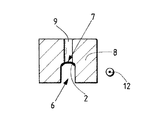
繊維通路6の形成、吸着ベルト2の下側ベルト部分のガイド、並びに必要な誘引通風を生じさせる真空チャンバ9の配設を、図2a〜2dが示す。
Figures 2a to 2d show the formation of the
繊維通路6の底部は、部分的に、すなわち特にストランド構成ゾーンZの領域内を、U字形に丸みを付けられているので、吸着ベルト2の下側ベルト部分2aも、仕上がったフィルタストランドの所望の輪郭となる。
Since the bottom of the
図1による装置の種々の横断面を概略的に図示する図2a〜2dが示すように、真空チャンバ9は、繊維通路6のほぼ全長に渡って延在し、吸着ベルト2の移送方向に対して横に吸着ベルト2の少なくとも一部に付設されている。図2a〜2cには、吸着ベルト2の移送方向に対して横に真空チャンバ9が完全には吸着ベルト2の幅と同じ広さに達していないことが図示されている。但し、吸着ベルト2の幅もしくは移送方向に対して横に吸引通路もしくは真空チャンバ9が吸着ベルト全体をカバーすると見ることもできる。吸着ベルト2が真空チャンバ9内に吸い込まれないように、吸気スリットもしくは吸気口を有するガイド本体8の通気性の底部7が設けられている。底部は、例えば孔が開けられている。特許文献1に従って、真空が相応に設定可能に制御することができるようになっており、例えば吸着ベルトのサイドストリップにセンタストリップから分けて吸気の作用を加える真空チャンバを設けることもできる。
As shown in FIGS. 2 a-2 d, which schematically illustrate various cross-sections of the device according to FIG. 1, the
ストランド構成ゾーンZの下流には、過剰なタバコ16aをタバコストランド16から除去する過剰分除去装置19が配設されている。過剰分除去装置19は、トリマともよばれ、例えば1つ又は2つの円形カッタ28を有し、この円形カッタは、回転するように形成されており、その切断円は、過剰分を除去するためにストランドの領域内で接する。優れたことに、円形カッタ28は、仕上がったストランドの所望の輪郭の少なくとも一部に少なくとも近似的に相応する横断面輪郭を過剰分を除去する際に繊維ストランドに与えるように形成もしくは配設されている。相応の実施形が特許文献1に図示されている。
An excess removing
吸着ベルト2もしくは繊維通路6の排出端21は、繊維ストランドを矢印方向23aに供給される被覆材料テープ23、例えばシガレット紙テープ又はフィルタ紙テープで被覆するサイジング装置22の紙の入口の上に位置する。循環するサイジングベルト24は、被覆材料テープ23とその上に載せられる繊維ストランド16を入口フィンガ26の下を通してサイジング装置22に移送し、僅かな予成形力しか加える必要がないので、繊維通路の丸みを付けた底部7によって予め成形されたストランド輪郭がサイジング装置と被覆材にストランドが入るのを容易にする。吸着ベルト2の真直ぐな横断面輪郭もしくはストランド構成ゾーンZ内の横断面輪郭と比べて若干湾曲した吸着ベルト2の横断面輪郭を短時間設けることは、驚くほど問題ないが、これは、繊維が、真直ぐもしくは若干湾曲した輪郭にさらされる速さもしくは短い時間の間ほとんど真直ぐもしくは若干湾曲した輪郭に従わず、本質的に予め成形された湾曲した輪郭のまま残っているからである。この場合、本発明によれば、図1で右に配設された真直ぐなエッジを有する通常の入口フィンガ26を設けることができ、この入口フィンガは、それ自身タバコ加工産業では公知であり、このような入口フィンガとそれ自身吸着ストランドコンベヤ全体に渡って設けられた真直ぐな吸着ベルト2の横断面輪郭によるストランドを構成する技術は、非常に良好に開発されている。
The
繊維ストランド16は、過剰分を除去した後サイジング装置の入口領域で有利なことに既に凹に成形された被覆材料テープ上に載せられるので、過剰分の除去時に繊維ストランドが維持している横断面輪郭は、十分に維持されたままであり、加えるべき予成形作業の低減によりサイジング装置の入るのを容易にする。
Since the
負圧チャンバ9は、サイジング装置22の入口領域の上で終了する。但し、サイジング装置は、転向ローラ3aもしくは入口フィンガ26の移送方向で上流のエッジ、即ち剥離領域20にまで延在する。転向ローラ3aは、プレスローラとして形成してもよい。
The
加えて、図1には圧縮手段33が図示されているが、これは、例えばハウジング34の図示してないシリンダ状の収容部に回転可能に支承された図示してない回転式制御ディスクから構成することができ、圧縮された部分をストランドに設けるために使用される。圧縮装置33の詳細な説明は、特許文献1から読み取ることができる。
In addition, FIG. 1 shows the compression means 33, which comprises, for example, a rotary control disk (not shown) that is rotatably supported in a cylindrical housing (not shown) of the
図2a〜2cは、図1の種々の断面におけるガイド本体8の横断面図を示す。図2aは、切断線E−Eに沿った断面図を示す。これは、負圧チャンバ9の開始部を通る断面図である。負圧チャンバ9内を相応の負圧が支配するので吸着ベルト2が密着する通気性の底部7が図示されている。ガイド本体は、ここでは、吸着ベルト2が移送方向に対して横に、もしくはその横断面輪郭が真直ぐに形成されるように形成されている。更に、図2aには移送方向12が図示されている。
2a to 2c show cross-sectional views of the
図2bは、切断線A−A及びD−Dに沿った概略断面図を示す。この場合、通気性の底部7は既に湾曲した状態に形成されており、通気性の底部の側面、特に負圧によって作用を受けない側面は、強く湾曲させることができる。湾曲の半径は、図2cによる湾曲と比べて大きい。図2b及び2cでは、部分円状の輪郭が設けられている。この場合、A−Aによって図示された断面の移送方向で比較的直ぐ後に、B−BもしくはC−Cに沿った断面を図示すべき図2cにより概略的に図示された横断面輪郭が続く。ここには、ガイド本体8の半円形の通気性の底部7が図示されており、これにより、吸着ベルト2の半円形の横断面輪郭が得られる。
FIG. 2b shows a schematic cross-sectional view along section lines AA and DD. In this case, the
図2dは、切断線F−Fに沿った概略断面図を示す。その前の断面におけるような不圧チャンバ9がもはや存在しない。加えて、ガイド本体8の底部7’は、この箇所ではもはや通気性を有しておらず、横断面輪郭が再び真直ぐに形成されている。
FIG. 2d shows a schematic cross-sectional view along the section line FF. There is no longer a
本発明による装置と本発明による方法により、タバコ及びフィルタ繊維から成る繊維ストランドは効果的に製造することができる。入口フィンガ26による繊維ストランドの引渡しの領域では、その前よりも若干湾曲するように、優れたことに真直ぐに形成されており、これにより、効果的で簡単な材料の引渡しが可能である。これにより、吸着ベルト2を転向させることは、簡単に可能である。加えて、スクレーパとして形成してもよい入口フィンガ26は、機能技術と比べて変更することができず、これにより、成りにくい形状が生じる。繊維巣地ランドは、吸着ストランドコンベヤからは成れた直後に、サイジング装置内で円形又は楕円形に成形される。吸着ベルト2の横断面輪郭が真直ぐな区間は、優れたことに非常に短く、例えば10cmよりも小さい。
By means of the device according to the invention and the method according to the invention, fiber strands consisting of tobacco and filter fibers can be produced effectively. In the region of fiber strand delivery by the
吸着ベルト2の形状が一時的に変更されるにもかかわらず、繊維ストランドは、その構築時の元の形状を留め、横断面輪郭が真直ぐな吸着ベルト上で構築する際よりも丸い繊維ストランドが生じる。これにより、繊維ストランドの真円度に関して高い品質向上が得られる。
Although the shape of the
1 吸着ストランドコンベヤ
2 吸着ベルト
2a 下側ベルト部分
3a 転向ローラ
3b 転向ローラ
4 ガイドローラ
6 繊維通路
7 通気性の底部
7’ 非通気性の底部
8 ガイド本体
9 真空チャンバ
11 真空源
12 移送方向
13 移送シャフト
14 繊維移送方向
16 繊維ストランド
16a 過剰な繊維
19 過剰分除去装置
20 剥離領域
21 排出端
22 サイジング装置
23 被覆材料テープ
23a 矢印方向
24 サイジングベルト
26 入口フィンガ
28 円形カッタ
33 圧縮装置
34 ハウジング
Z ストランド構成ゾーン
DESCRIPTION OF SYMBOLS 1
Claims (9)
コンベヤベルト(2)上又はコンベヤベルト(2)に沿って構成可能なストランド(16)の剥離領域(20)内のコンベヤベルト(2)の横断面輪郭が、若干湾曲したものから真直ぐなものになっていることを特徴とする吸着ストランドコンベヤ。 Guide device (8) for guiding the conveyor belt (2), in which the conveyor belt (2) can be transferred in the transfer direction (12) in the fiber passage (6) and which sets the cross-sectional profile of the conveyor belt (2) The conveyor belt (2) in the fiber supply area (Z) of the fiber passage (6) has a curved cross-sectional profile, and in this fiber supply area (Z) the fibers are conveyed by a negative pressure to the conveyor belt ( In the adsorption strand conveyor (1) of the tobacco processing industry with fiber passages (6) adsorbed on 2)
The cross-sectional profile of the conveyor belt (2) in the peeling region (20) of the strand (16) that can be configured on or along the conveyor belt (2) is changed from slightly curved to straight Adsorption strand conveyor characterized by becoming.
−繊維供給領域(Z)内のコンベヤベルト(2)が湾曲した横断面輪郭を少なくとも部分的に備え、吸着ストランドコンベヤ(1)の繊維供給領域(Z)内で吸着ストランドコンベヤ(1)のコンベヤベルト(2)上に繊維を供給し、繊維供給領域(Z)において繊維は負圧によりコンベヤベルト(2)に吸着されるステップと、
−排出領域(20)内のコンベヤベルト(2)の横断面輪郭が若干湾曲したものから真直ぐなものになるように形成されており、供給された繊維を排出領域(20)の方向(12)に移送するステップと
を有するタバコ加工産業のストランド(16)を製造するための方法。 The following method steps:
The conveyor belt (2) in the fiber supply zone (Z) is at least partly provided with a curved cross-sectional profile, the conveyor of the suction strand conveyor (1) in the fiber supply zone (Z) of the suction strand conveyor (1) Supplying fibers onto the belt (2), wherein the fibers are adsorbed to the conveyor belt (2) by negative pressure in the fiber supply region (Z) ;
The conveyor belt (2) in the discharge area (20) is shaped so that the cross-sectional profile of the conveyor belt (2) is slightly curved to straight, and the supplied fibers are directed in the direction of the discharge area (20) (12) For producing a strand (16) of the tobacco processing industry.
Applications Claiming Priority (2)
| Application Number | Priority Date | Filing Date | Title |
|---|---|---|---|
| DE102006045810.9 | 2006-09-26 | ||
| DE102006045810A DE102006045810B4 (en) | 2006-09-26 | 2006-09-26 | Suction-belt conveyor and method for producing a strand of the tobacco-processing industry |
Publications (3)
| Publication Number | Publication Date |
|---|---|
| JP2008081320A JP2008081320A (en) | 2008-04-10 |
| JP2008081320A5 JP2008081320A5 (en) | 2010-10-14 |
| JP5297618B2 true JP5297618B2 (en) | 2013-09-25 |
Family
ID=38980617
Family Applications (1)
| Application Number | Title | Priority Date | Filing Date |
|---|---|---|---|
| JP2007246858A Expired - Fee Related JP5297618B2 (en) | 2006-09-26 | 2007-09-25 | Adsorbent strand conveyor and method for producing strands in the tobacco processing industry |
Country Status (6)
| Country | Link |
|---|---|
| EP (1) | EP1905315B1 (en) |
| JP (1) | JP5297618B2 (en) |
| CN (1) | CN101152020B (en) |
| AT (1) | ATE500754T1 (en) |
| DE (2) | DE102006045810B4 (en) |
| PL (1) | PL1905315T3 (en) |
Families Citing this family (6)
| Publication number | Priority date | Publication date | Assignee | Title |
|---|---|---|---|---|
| DE102009021811A1 (en) * | 2009-05-18 | 2010-11-25 | Hauni Maschinenbau Ag | Suction-belt conveyor and method for producing a strand of the tobacco-processing industry |
| DE102009022759A1 (en) * | 2009-05-26 | 2010-12-02 | Hauni Maschinenbau Ag | Preparation of a filter material strip of the tobacco processing industry |
| DE102011100365A1 (en) * | 2010-06-29 | 2011-12-29 | Hauni Maschinenbau Ag | Device for producing rod-shaped products of the tobacco-processing industry |
| DE102012200163B4 (en) * | 2012-01-06 | 2013-12-05 | Hauni Maschinenbau Ag | Saugstrangförderereinrichtung a machine of the tobacco processing industry |
| DE102013223308A1 (en) * | 2013-11-15 | 2015-05-21 | Hauni Maschinenbau Ag | Suction belt of a machine of the tobacco processing industry |
| PL3171717T3 (en) * | 2014-07-22 | 2021-04-19 | Jt International Sa | Method and apparatus for forming a filter rod |
Family Cites Families (11)
| Publication number | Priority date | Publication date | Assignee | Title |
|---|---|---|---|---|
| DE2827813A1 (en) * | 1977-07-08 | 1979-01-25 | Molins Ltd | CIGARETTE MAKING MACHINE |
| IT1181267B (en) * | 1984-12-10 | 1987-09-23 | Gd Spa | CONTINUOUS TYPE CIGARETTES PACKAGING MACHINE |
| DE3627057A1 (en) * | 1985-08-22 | 1987-02-26 | Hauni Werke Koerber & Co Kg | Method and apparatus for producing a tobacco strand |
| US5370136A (en) | 1992-11-11 | 1994-12-06 | Molins Plc | Cigarette making machine |
| CN1163078A (en) * | 1996-03-12 | 1997-10-29 | G.D公司 | Method and device for continuously supplying band material into machine |
| GB9626619D0 (en) * | 1996-12-20 | 1997-02-05 | Molins Plc | Cigarette making machine |
| DE19733443A1 (en) * | 1997-08-02 | 1999-02-04 | Hauni Maschinenbau Ag | Device for conveying a strand of the tobacco processing industry |
| TW426506B (en) * | 1998-08-06 | 2001-03-21 | Japan Tobacco Inc | Belt conveyor type compression forming apparatus for tobacco stream |
| DE10145327A1 (en) * | 2001-09-14 | 2003-04-03 | Hauni Maschinenbau Ag | Sizing set for a rod machine in the tobacco processing industry |
| DE10202847A1 (en) * | 2002-01-24 | 2003-08-07 | Hauni Maschinenbau Ag | Entry finger of a format device |
| FR2861957B1 (en) * | 2003-11-12 | 2006-01-21 | Jose Valderrama | CIRCULAR OR POLYGONAL TOBACCO CEILING |
-
2006
- 2006-09-26 DE DE102006045810A patent/DE102006045810B4/en not_active Expired - Fee Related
-
2007
- 2007-09-21 PL PL07018547T patent/PL1905315T3/en unknown
- 2007-09-21 AT AT07018547T patent/ATE500754T1/en active
- 2007-09-21 DE DE502007006650T patent/DE502007006650D1/en active Active
- 2007-09-21 EP EP07018547A patent/EP1905315B1/en not_active Not-in-force
- 2007-09-25 JP JP2007246858A patent/JP5297618B2/en not_active Expired - Fee Related
- 2007-09-26 CN CN200710153115.4A patent/CN101152020B/en not_active Expired - Fee Related
Also Published As
| Publication number | Publication date |
|---|---|
| CN101152020A (en) | 2008-04-02 |
| DE102006045810B4 (en) | 2012-02-16 |
| DE502007006650D1 (en) | 2011-04-21 |
| JP2008081320A (en) | 2008-04-10 |
| CN101152020B (en) | 2014-07-23 |
| EP1905315B1 (en) | 2011-03-09 |
| PL1905315T3 (en) | 2011-08-31 |
| EP1905315A1 (en) | 2008-04-02 |
| DE102006045810A1 (en) | 2008-04-03 |
| ATE500754T1 (en) | 2011-03-15 |
Similar Documents
| Publication | Publication Date | Title |
|---|---|---|
| JP5297618B2 (en) | Adsorbent strand conveyor and method for producing strands in the tobacco processing industry | |
| EP2893820B1 (en) | Method for producing filter cigarette, filter, and filter cigarette | |
| JP4584371B2 (en) | Method and apparatus for processing filter tow strips | |
| JP4093718B2 (en) | Equipment for transporting continuum in the tobacco processing industry | |
| EP2679106A1 (en) | Cigarette filter manufacturing device and cigarette filter manufacturing method | |
| JP3615793B2 (en) | Equipment for removing excess amounts of tobacco from a tobacco continuum | |
| US5810016A (en) | Compression molding apparatus for a cut tobacco layer in a cigarette manufacturing machine | |
| US7588524B2 (en) | Fiber filter production | |
| JP2008081320A5 (en) | ||
| JPH08256750A (en) | Apparatus for guiding out excess operational air from distributor in tobacco processing machine | |
| JPS60118178A (en) | Apparatus for taking off excessive tobacco from tobacco stream | |
| US20060194683A1 (en) | Processing of a filter material band in the tobacco industry | |
| CN102197884B (en) | Suction belt of machine in tobacco processing industry | |
| US7380552B2 (en) | Unit for forming a continuous mat of tobacco | |
| US5494053A (en) | Cigarette making machine | |
| JP4945071B2 (en) | Apparatus and method for producing at least two fiber continuums | |
| GB2179233A (en) | Apparatus for making cigarettes with dense ends | |
| PL358113A1 (en) | Apparatus for preparing at least one web of filter material for tobacco processing industry and method of preparing at least one wqeb of ilter material for tobacco processing industry | |
| JP4033399B2 (en) | Filter mounting device | |
| KR20120071390A (en) | Tow cutter | |
| JPS6244159A (en) | Method and apparatus for producing tobacco strand | |
| JP5524710B2 (en) | Preparation of filter strips for the tobacco processing industry | |
| US5622189A (en) | Cigarette making machine | |
| JP2019503692A (en) | Machine for forming tobacco filter and method for forming tobacco filter | |
| JP2017189161A (en) | Method and machine for production of smoking articles |
Legal Events
| Date | Code | Title | Description |
|---|---|---|---|
| RD04 | Notification of resignation of power of attorney |
Free format text: JAPANESE INTERMEDIATE CODE: A7424 Effective date: 20100518 |
|
| A521 | Request for written amendment filed |
Free format text: JAPANESE INTERMEDIATE CODE: A523 Effective date: 20100901 |
|
| A621 | Written request for application examination |
Free format text: JAPANESE INTERMEDIATE CODE: A621 Effective date: 20100901 |
|
| A977 | Report on retrieval |
Free format text: JAPANESE INTERMEDIATE CODE: A971007 Effective date: 20120920 |
|
| A131 | Notification of reasons for refusal |
Free format text: JAPANESE INTERMEDIATE CODE: A131 Effective date: 20121016 |
|
| TRDD | Decision of grant or rejection written | ||
| A01 | Written decision to grant a patent or to grant a registration (utility model) |
Free format text: JAPANESE INTERMEDIATE CODE: A01 Effective date: 20130528 |
|
| A61 | First payment of annual fees (during grant procedure) |
Free format text: JAPANESE INTERMEDIATE CODE: A61 Effective date: 20130617 |
|
| R150 | Certificate of patent or registration of utility model |
Free format text: JAPANESE INTERMEDIATE CODE: R150 |
|
| LAPS | Cancellation because of no payment of annual fees |