JP5292191B2 - Disc brake and manufacturing method thereof - Google Patents

Disc brake and manufacturing method thereof Download PDF

Info

Publication number
JP5292191B2
JP5292191B2 JP2009137328A JP2009137328A JP5292191B2 JP 5292191 B2 JP5292191 B2 JP 5292191B2 JP 2009137328 A JP2009137328 A JP 2009137328A JP 2009137328 A JP2009137328 A JP 2009137328A JP 5292191 B2 JP5292191 B2 JP 5292191B2
Authority
JP
Japan
Prior art keywords
bore
caliper body
cylinder
disc
caliper
Prior art date
Legal status (The legal status is an assumption and is not a legal conclusion. Google has not performed a legal analysis and makes no representation as to the accuracy of the status listed.)
Active
Application number
JP2009137328A
Other languages
Japanese (ja)
Other versions
JP2010281429A (en
JP2010281429A5 (en
Inventor
伸二 鈴木
隆裕 徳永
Current Assignee (The listed assignees may be inaccurate. Google has not performed a legal analysis and makes no representation or warranty as to the accuracy of the list.)
Hitachi Astemo Ltd
Original Assignee
Hitachi Automotive Systems Ltd
Priority date (The priority date is an assumption and is not a legal conclusion. Google has not performed a legal analysis and makes no representation as to the accuracy of the date listed.)
Filing date
Publication date
Application filed by Hitachi Automotive Systems Ltd filed Critical Hitachi Automotive Systems Ltd
Priority to JP2009137328A priority Critical patent/JP5292191B2/en
Priority to US12/793,916 priority patent/US8991563B2/en
Priority to DE102010029727.5A priority patent/DE102010029727B4/en
Priority to CN201010198740.2A priority patent/CN101907139B/en
Publication of JP2010281429A publication Critical patent/JP2010281429A/en
Publication of JP2010281429A5 publication Critical patent/JP2010281429A5/ja
Application granted granted Critical
Publication of JP5292191B2 publication Critical patent/JP5292191B2/en
Active legal-status Critical Current
Anticipated expiration legal-status Critical

Links

Images

Classifications

    • FMECHANICAL ENGINEERING; LIGHTING; HEATING; WEAPONS; BLASTING
    • F16ENGINEERING ELEMENTS AND UNITS; GENERAL MEASURES FOR PRODUCING AND MAINTAINING EFFECTIVE FUNCTIONING OF MACHINES OR INSTALLATIONS; THERMAL INSULATION IN GENERAL
    • F16DCOUPLINGS FOR TRANSMITTING ROTATION; CLUTCHES; BRAKES
    • F16D55/00Brakes with substantially-radial braking surfaces pressed together in axial direction, e.g. disc brakes
    • F16D55/02Brakes with substantially-radial braking surfaces pressed together in axial direction, e.g. disc brakes with axially-movable discs or pads pressed against axially-located rotating members
    • F16D55/22Brakes with substantially-radial braking surfaces pressed together in axial direction, e.g. disc brakes with axially-movable discs or pads pressed against axially-located rotating members by clamping an axially-located rotating disc between movable braking members, e.g. movable brake discs or brake pads
    • FMECHANICAL ENGINEERING; LIGHTING; HEATING; WEAPONS; BLASTING
    • F16ENGINEERING ELEMENTS AND UNITS; GENERAL MEASURES FOR PRODUCING AND MAINTAINING EFFECTIVE FUNCTIONING OF MACHINES OR INSTALLATIONS; THERMAL INSULATION IN GENERAL
    • F16DCOUPLINGS FOR TRANSMITTING ROTATION; CLUTCHES; BRAKES
    • F16D55/00Brakes with substantially-radial braking surfaces pressed together in axial direction, e.g. disc brakes
    • F16D2055/0004Parts or details of disc brakes
    • F16D2055/0016Brake calipers
    • F16D2055/002Brake calipers assembled from a plurality of parts
    • FMECHANICAL ENGINEERING; LIGHTING; HEATING; WEAPONS; BLASTING
    • F16ENGINEERING ELEMENTS AND UNITS; GENERAL MEASURES FOR PRODUCING AND MAINTAINING EFFECTIVE FUNCTIONING OF MACHINES OR INSTALLATIONS; THERMAL INSULATION IN GENERAL
    • F16DCOUPLINGS FOR TRANSMITTING ROTATION; CLUTCHES; BRAKES
    • F16D2121/00Type of actuator operation force
    • F16D2121/02Fluid pressure
    • FMECHANICAL ENGINEERING; LIGHTING; HEATING; WEAPONS; BLASTING
    • F16ENGINEERING ELEMENTS AND UNITS; GENERAL MEASURES FOR PRODUCING AND MAINTAINING EFFECTIVE FUNCTIONING OF MACHINES OR INSTALLATIONS; THERMAL INSULATION IN GENERAL
    • F16DCOUPLINGS FOR TRANSMITTING ROTATION; CLUTCHES; BRAKES
    • F16D2250/00Manufacturing; Assembly
    • F16D2250/0061Joining
    • F16D2250/0076Welding, brazing

Abstract

An object of the present invention is to provide a disk brake and a method of making the disk brake capable of improving the efficiency of manufacturing a caliper. A bottom portion 41 of a bore 40 is formed by integrally welding an opening surrounding portion at the bottom portion 41 side of a cylinder portion 35 and a bottom cover member 92 fitted to the opening surrounding portion by friction stir welding. The bottom cover member 92 is formed into a disk shape, and provided with a protrusion 68 at one surface side facing the interior of the bore 40, and an inflow hole 58 for a supply of a fluid pressure into the bore 40 formed within the range of the protrusion 68 to establish communication between one surface 71 and the other surface 63.

Description

本発明は、ディスクブレーキおよびその製造方法に関する。   The present invention relates to a disc brake and a manufacturing method thereof.

シリンダのボアの底部に底蓋部材を摩擦攪拌接合により一体に接合するキャリパを有するディスクブレーキがある(例えば、特許文献1参照)。   There is a disc brake having a caliper that integrally joins a bottom cover member by friction stir welding to the bottom of a bore of a cylinder (see, for example, Patent Document 1).

特開2007−10136号公報JP 2007-10136 A

ディスクブレーキのキャリパには、液圧を供給するための流入孔がシリンダのボアの底部に設けられるものがある。このような構造のキャリパに、上記した摩擦攪拌接合を適用した場合に、製造効率が低下する可能性があった。   Some disc brake calipers are provided with an inflow hole for supplying hydraulic pressure at the bottom of a cylinder bore. When the above-described friction stir welding is applied to the caliper having such a structure, there is a possibility that the manufacturing efficiency is lowered.

したがって、本発明は、キャリパの製造効率を向上させることができるディスクブレーキおよびその製造方法の提供を目的とする。   Accordingly, an object of the present invention is to provide a disc brake capable of improving the caliper manufacturing efficiency and a manufacturing method thereof.

上記目的を達成するために、本発明のディスクブレーキは、シリンダ部の開口周縁部に嵌合され摩擦攪拌接合により一体に接合される底蓋部材が、円盤状に形成され、前記開口周縁部に嵌合する嵌合円筒面と、前記ボア内に臨む一面側に前記嵌合円筒面の一端縁部から内側に軸線方向に直交して形成される底面構成面と、該底面構成面よりも前記ボア内に突出した凸部が設けられるとともに、前記ボアに液圧を供給するための流入孔が前記凸部の範囲内で前記一面と他面とを連通して設けられている。 In order to achieve the above object, in the disc brake of the present invention, a bottom cover member that is fitted to the opening peripheral portion of the cylinder portion and integrally joined by friction stir welding is formed in a disc shape , A fitting cylindrical surface to be fitted, a bottom surface forming surface formed perpendicular to the axial direction inwardly from one end edge of the fitting cylindrical surface on one surface side facing the bore, and the bottom surface forming surface than the bottom surface forming surface A convex portion protruding into the bore is provided, and an inflow hole for supplying hydraulic pressure to the bore is provided in communication with the one surface and the other surface within the range of the convex portion.

本発明のディスクブレーキの製造方法は、両端が開口となっているシリンダ部と、ディスクを跨ぐために前記シリンダ部の径方向外方でその軸方向へ延びるブリッジ部とを有するキャリパボディ本体を準備する工程と、円盤状に形成され、前記開口周縁部に嵌合する嵌合円筒面と、一面側に前記嵌合円筒面の一端縁部から内側に軸線方向に直交して形成される底面構成面と、該底面構成面よりも前記ボア内に突出した凸部が設けられる底蓋部材を準備する工程と、前記シリンダ部の底部側の開口周縁部に、前記凸部を前記シリンダ部の内側に配置した状態で前記底蓋部材を摩擦攪拌接合により一体的に接合する工程と、キャリパ本体に接合された前記底蓋部材に、前記凸部の範囲内で前記一面と他面とを連通する流入孔を切削加工する工程とを有する。 The disc brake manufacturing method of the present invention prepares a caliper body main body having a cylinder portion having both ends open and a bridge portion extending radially outward of the cylinder portion in the axial direction so as to straddle the disc. And a fitting cylindrical surface that is formed in a disc shape and is fitted to the peripheral edge of the opening , and a bottom surface that is formed on one surface side from one end edge of the fitting cylindrical surface to be orthogonal to the axial direction. When a step of preparing a bottom cover member and the convex portion than the bottom surface configuration surface projecting into said bore is provided, the opening edge portion of the bottom side of the cylinder portion, the inside of the convex portion of the cylinder portion The bottom cover member is integrally joined by friction stir welding in a state of being arranged in the position, and the bottom cover member joined to the caliper body is communicated with the one surface and the other surface within the range of the convex portion. Cutting the inflow hole Having.

本発明によれば、キャリパの製造効率を向上させることができる。   According to the present invention, the caliper manufacturing efficiency can be improved.

本発明に係る第1実施形態のディスクブレーキを示す平面図である。It is a top view which shows the disc brake of 1st Embodiment which concerns on this invention. 本発明に係る第1実施形態のディスクブレーキを示す正面図である。It is a front view which shows the disc brake of 1st Embodiment which concerns on this invention. 本発明に係る第1実施形態のディスクブレーキのキャリパボディを示す背面図である。It is a rear view which shows the caliper body of the disc brake of 1st Embodiment which concerns on this invention. 本発明に係る第1実施形態のディスクブレーキのキャリパボディを示す正面図である。It is a front view which shows the caliper body of the disc brake of 1st Embodiment which concerns on this invention. 本発明に係る第1実施形態のディスクブレーキのキャリパボディ、ピストンおよび配管類を示す断面図である。It is sectional drawing which shows the caliper body, piston, and piping of the disc brake of 1st Embodiment which concern on this invention. 本発明に係る第1実施形態のディスクブレーキのキャリパボディ本体を示す断面図である。It is sectional drawing which shows the caliper body main body of the disc brake of 1st Embodiment which concerns on this invention. 本発明に係る第1実施形態のディスクブレーキの底蓋部材を示す断面図である。It is sectional drawing which shows the bottom cover member of the disc brake of 1st Embodiment which concerns on this invention. 本発明に係る第1実施形態のディスクブレーキのキャリパボディの摩擦攪拌接合の状況を示す断面図である。It is sectional drawing which shows the condition of the friction stir welding of the caliper body of the disc brake of 1st Embodiment which concerns on this invention. 本発明に係る第1実施形態のディスクブレーキのキャリパボディを示す断面図である。It is sectional drawing which shows the caliper body of the disc brake of 1st Embodiment which concerns on this invention. 本発明に係る第1実施形態のディスクブレーキのキャリパボディおよびピストンを示す断面図である。It is sectional drawing which shows the caliper body and piston of the disc brake of 1st Embodiment which concern on this invention. 本発明に係る第2実施形態のディスクブレーキのキャリパボディおよびピストンを示す断面図である。It is sectional drawing which shows the caliper body and piston of the disc brake of 2nd Embodiment which concern on this invention. 本発明に係る第3実施形態のディスクブレーキのキャリパボディ、ピストンおよび配管類を示す断面図である。It is sectional drawing which shows the caliper body, piston, and piping of the disc brake of 3rd Embodiment concerning this invention. 本発明に係る第3実施形態のディスクブレーキの回止ピンを示す斜視図である。It is a perspective view which shows the rotation stop pin of the disc brake of 3rd Embodiment which concerns on this invention. 本発明に係る第3実施形態のディスクブレーキのキャリパボディを示す背面図である。It is a rear view which shows the caliper body of the disc brake of 3rd Embodiment which concerns on this invention. 本発明に係る第4実施形態のディスクブレーキのキャリパボディ、ピストンおよび配管類を示す断面図である。It is sectional drawing which shows the caliper body, piston, and piping of the disc brake of 4th Embodiment concerning this invention.

以下、本発明に係る各実施形態について図面を参照して説明する。   Hereinafter, each embodiment according to the present invention will be described with reference to the drawings.

「第1実施形態」
本発明に係る第1実施形態を図1〜図10に基づいて説明する。
“First Embodiment”
1st Embodiment which concerns on this invention is described based on FIGS.

第1実施形態のディスクブレーキは、四輪自動車の制動用のディスクブレーキである。図面では、車両の左右方向一側に配置されるものを図示しており、これに対し車両の左右方向逆側に配置されるものは鏡面対称形状をなすことになる。   The disc brake of the first embodiment is a disc brake for braking a four-wheeled vehicle. In the drawing, what is arranged on one side in the left-right direction of the vehicle is shown, and what is arranged on the opposite side in the left-right direction of the vehicle has a mirror-symmetric shape.

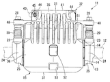
図1に示すように、このディスクブレーキ11は、キャリア13と、一対のブレーキパッド14と、キャリパ15とを備えている。キャリア13は、制動対象となる図示略の車輪(回転体)とともに回転するディスク12の外径側を跨ぐように配置されて車両の非回転部に固定される。一対のブレーキパッド14は、ディスク12の両面に対向配置された状態でディスク12の軸線方向に摺動可能となるようにキャリア13に支持される。キャリパ15は、ディスク12の外径側を跨いだ状態でディスク12の軸線方向に摺動可能となるようにキャリア13に支持されてブレーキパッド14をディスク12に押圧することによりディスク12に摩擦抵抗を付与する。なお、以下においては、ディスク12の半径方向をディスク半径方向と称し、ディスク12の軸線方向をディスク軸線方向と称し、ディスク12の回転方向をディスク回転方向と称す。   As shown in FIG. 1, the disc brake 11 includes a carrier 13, a pair of brake pads 14, and a caliper 15. The carrier 13 is disposed so as to straddle the outer diameter side of the disk 12 that rotates together with a wheel (rotating body) (not shown) to be braked, and is fixed to a non-rotating portion of the vehicle. The pair of brake pads 14 are supported by the carrier 13 so as to be slidable in the axial direction of the disk 12 in a state of being opposed to both surfaces of the disk 12. The caliper 15 is supported by the carrier 13 so as to be slidable in the axial direction of the disk 12 while straddling the outer diameter side of the disk 12, and the brake pad 14 is pressed against the disk 12 to cause frictional resistance to the disk 12. Is granted. In the following, the radial direction of the disk 12 is referred to as a disk radial direction, the axial direction of the disk 12 is referred to as a disk axial direction, and the rotational direction of the disk 12 is referred to as a disk rotational direction.

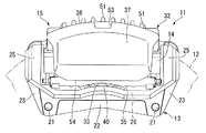
キャリア13は、図2に示すように、基板部22と、一対のインナ側パッド支持部23と、一対の連結部24と、一対のアウタ側パッド支持部25と、ビーム部26とを有して一体的に構成されている。基板部22は、ディスク回転方向に延在する姿勢でディスク12よりも車両内側(インナ側)に配置されるとともにそのディスク回転方向の両端側に車両への取付穴21が形成されている。一対のインナ側パッド支持部23は、基板部22のディスク回転方向両端からディスク半径方向外側に延出して設けられている。一対の連結部24は、図1に示すように、インナ側パッド支持部23のディスク半径方向外端からディスク12の半径方向外側を越えるようにディスク軸線方向に沿って車両外側(アウタ側)に突出して形成されている。一対のアウタ側パッド支持部25は、一対の連結部24のインナ側パッド支持部23とは反対側から図2に示すようにディスク半径方向内方にそれぞれ延出して形成されている。ビーム部26は、アウタ側パッド支持部25のディスク半径方向内側同士を連結するように形成されている。そして、図1に示すように、一対のインナ側パッド支持部23がインナ側のブレーキパッド14を摺動可能に支持し、一対のアウタ側パッド支持部25がアウタ側のブレーキパッド14を摺動可能に支持する。   As shown in FIG. 2, the carrier 13 includes a substrate part 22, a pair of inner side pad support parts 23, a pair of connection parts 24, a pair of outer side pad support parts 25, and a beam part 26. Are integrally configured. The board portion 22 is disposed on the vehicle inner side (inner side) than the disc 12 in a posture extending in the disc rotation direction, and mounting holes 21 for the vehicle are formed on both ends in the disc rotation direction. The pair of inner side pad support portions 23 are provided so as to extend outward from the both ends of the substrate portion 22 in the disc rotation direction in the disc radial direction. As shown in FIG. 1, the pair of connecting portions 24 are arranged on the vehicle outer side (outer side) along the disc axial direction so as to extend from the outer end in the disc radial direction of the inner side pad support portion 23 to the outer side in the radial direction of the disc 12. Protrusively formed. The pair of outer side pad support portions 25 are formed to extend inward in the disk radial direction as shown in FIG. 2 from the side opposite to the inner side pad support portion 23 of the pair of connecting portions 24. The beam portion 26 is formed so as to connect the inner sides in the disk radial direction of the outer side pad support portion 25. As shown in FIG. 1, the pair of inner side pad support portions 23 slidably supports the inner side brake pad 14, and the pair of outer side pad support portions 25 slides on the outer side brake pad 14. Support as possible.

ここで、キャリア13には、ディスク回転方向の両端におけるディスク半径方向外側となる一対の連結部24の位置に、ディスク軸線方向に摺動可能となるように支持ピン28がそれぞれインナ側から嵌合されている。これら支持ピン28を介してキャリパ15がキャリア13に取り付けられる。なお、一対の支持ピン28のキャリパ15とキャリア13との間部分は伸縮可能な一対のブーツ29で被覆されている。   Here, support pins 28 are fitted to the carrier 13 from the inner side so as to be slidable in the disk axial direction at the positions of the pair of connecting portions 24 on the outer side in the disk radial direction at both ends in the disk rotation direction. Has been. The caliper 15 is attached to the carrier 13 through these support pins 28. A portion between the caliper 15 and the carrier 13 of the pair of support pins 28 is covered with a pair of boots 29 that can expand and contract.

キャリパ15は、ディスク12を跨いだ状態でキャリア13に支持ピン28を介して支持されるキャリパボディ32と、キャリパボディ32に保持されてディスク12の一面側に対向するように配置される図2に示すピストン33とを有している。   The caliper 15 is disposed so as to face the one surface side of the disk 12 held by the caliper body 32 supported by the carrier 13 via the support pins 28 while straddling the disk 12. And a piston 33 shown in FIG.

キャリパボディ32は、図1に示すように、シリンダ部35と、ブリッジ部36と、爪部37とを有して一体的に構成されている。シリンダ部35は、ディスク12の一方の面側であるインナ側に対向配置されている。ブリッジ部36は、ディスク12を跨ぐためにシリンダ部35の径方向外方でディスク12の軸方向へ延びて形成されている。爪部37は、ブリッジ部36のシリンダ部35とは反対側からディスク半径方向内方に延出してディスク12の他方の面側であるアウタ側に対向するようになっている。つまり、キャリパ15は、そのキャリパボディ32が、ディスク12の一方の面側にシリンダ部35が設けられ、ディスク12の他方の面側に爪部37が設けられ、爪部37とシリンダ部35とを接続するブリッジ部36がディスク12を跨いで設けられるフィスト型となっている。   As shown in FIG. 1, the caliper body 32 includes a cylinder portion 35, a bridge portion 36, and a claw portion 37, and is integrally configured. The cylinder portion 35 is disposed opposite to the inner side, which is one surface side of the disk 12. The bridge portion 36 is formed to extend in the axial direction of the disk 12 outside the cylinder portion 35 in order to straddle the disk 12. The claw portion 37 extends inward in the radial direction of the disc from the opposite side of the bridge portion 36 to the cylinder portion 35 and faces the outer side, which is the other surface side of the disc 12. That is, the caliper 15 has a caliper body 32 in which a cylinder portion 35 is provided on one surface side of the disk 12 and a claw portion 37 is provided on the other surface side of the disk 12. Is a fist type in which the bridge portion 36 is provided across the disk 12.

図2に示すように、シリンダ部35は、ディスク12側に開口するようにディスク軸線方向に沿うボア40が内部に形成された有底筒状をなしており、このボア40内にピストン33が挿入されている。そして、キャリパ15は、ボア40内に導入される液圧によりピストン33をディスク12側に前進させ、ピストン33でインナ側のブレーキパッド14を押圧してディスク12に接触させる。そして、ピストン33の押圧反力でキャリア13に対して支持ピン28を摺動させてシリンダ部35をディスク12から離す方向に移動して、爪部37でアウタ側のブレーキパッド14を押圧してディスク12に接触させる。このようにして、ピストン33と爪部37とで両側のブレーキパッド14を挟持してディスク12に押圧して摩擦抵抗を発生させ、制動力を発生させる。   As shown in FIG. 2, the cylinder portion 35 has a bottomed cylindrical shape in which a bore 40 along the disk axial direction is formed so as to open toward the disk 12, and a piston 33 is disposed in the bore 40. Has been inserted. The caliper 15 advances the piston 33 toward the disk 12 by the hydraulic pressure introduced into the bore 40, and presses the inner brake pad 14 with the piston 33 to contact the disk 12. Then, the support pin 28 is slid with respect to the carrier 13 by the pressing reaction force of the piston 33 to move the cylinder portion 35 away from the disk 12, and the outer brake pad 14 is pressed by the claw portion 37. Contact the disk 12. In this way, the brake pads 14 on both sides are sandwiched between the piston 33 and the claw portion 37 and pressed against the disk 12 to generate a frictional resistance, thereby generating a braking force.

ここで、キャリパボディ32は、車両への左右の取付勝手の違いに対しても、共通の鋳物素材が用いられる。これによって鋳物素材は、キャリパボディ32のディスク回転方向の中央を基準として対称の形状をなしている。このため、シリンダ部35の底部41側のディスク半径方向外側には、図1に示すエア抜き用のブリーダプラグ43を取り付けるためのブリーダボス44がディスク回転方向に離間して一対形成されている。そして、車両の左右方向一側に配置される図1に示すキャリパボディ32には、これら一対のブリーダボス44のうちの一方のみにブリーダプラグ43を取り付けるためのネジ穴からなるプラグ取付穴45が形成されており、他方にはプラグ取付穴45は形成されていない。なお、図1に示すキャリパボディ32と取付勝手が違う、車両の左右方向他側に配置されるキャリパボディ32には、一対のブリーダボス44のうち上記した他方のみにプラグ取付穴45が形成されることになる。   Here, the caliper body 32 is made of a common casting material for the difference in the right and left attachment to the vehicle. Thus, the casting material has a symmetrical shape with respect to the center of the caliper body 32 in the disk rotation direction. For this reason, a pair of bleeder bosses 44 for attaching the bleeder plugs 43 for releasing air shown in FIG. A caliper body 32 shown in FIG. 1 arranged on one side in the left-right direction of the vehicle is formed with a plug mounting hole 45 including a screw hole for mounting the bleeder plug 43 only in one of the pair of bleeder bosses 44. The plug mounting hole 45 is not formed on the other side. In addition, the caliper body 32 disposed on the other side in the left-right direction of the vehicle, which is different from the caliper body 32 shown in FIG. 1, has a plug mounting hole 45 formed only in the other of the pair of bleeder bosses 44. It will be.

図1に示すように、キャリパボディ32のシリンダ部35におけるディスク軸線方向の中間部には、ディスク回転方向両側に突出する一対のピン取付部48が、図3に示すようにボア40の中心よりもディスク半径方向のやや外側に形成されている。これらピン取付部48にはディスク軸線方向に沿ってピン取付穴49が形成されている。これらのピン取付穴49に図1に示す上記した支持ピン28が挿入状態で固定されることになる。   As shown in FIG. 1, a pair of pin mounting portions 48 projecting on both sides in the disc rotation direction are provided at the intermediate portion of the cylinder portion 35 of the caliper body 32 in the disc axial direction from the center of the bore 40 as shown in FIG. Is also formed slightly outside in the radial direction of the disk. These pin mounting portions 48 are formed with pin mounting holes 49 along the disk axial direction. The above-described support pins 28 shown in FIG. 1 are fixed to these pin mounting holes 49 in the inserted state.

図1に示すように、キャリパボディ32には、これらピン取付部48よりも爪部37側に、上記したブリッジ部36が、ディスク12の外周面に沿って湾曲する板状をなしてディスク回転方向に略一定幅で形成されている。このブリッジ部36の爪部37とは反対側の一部はシリンダ部35とディスク軸線方向にラップしている。ブリッジ部36には、主にこのラップ部分に、ディスク半径方向外側に突出しディスク軸線方向に延在するリブ51がディスク回転方向に並べられて複数形成されている。また、ブリッジ部36には、リブ51よりも爪部37側に、ディスク軸線方向に貫通する矩形状の窓部52がディスク回転方向の中央位置に形成されており、爪部37側の端部のディスク回転方向の中央位置にはディスク半径方向内方に凹む矩形状の段差部53が形成されている。   As shown in FIG. 1, the caliper body 32 has a plate-like shape in which the bridge portion 36 is curved along the outer peripheral surface of the disc 12 on the side of the claw portion 37 with respect to the pin mounting portion 48. It is formed with a substantially constant width in the direction. A part of the bridge portion 36 opposite to the claw portion 37 is wrapped with the cylinder portion 35 in the disk axial direction. In the bridge portion 36, a plurality of ribs 51 are formed mainly in the lap portion so as to protrude outward in the disc radial direction and extend in the disc axial direction. Further, the bridge portion 36 is formed with a rectangular window portion 52 penetrating in the disc axial direction on the claw portion 37 side of the rib 51 at the center position in the disc rotation direction. A rectangular step 53 that is recessed inward in the radial direction of the disk is formed at the center position in the disk rotation direction.

また、キャリパボディ32には、ブリッジ部36のシリンダ部35とは反対側に、上記した爪部37が、図4に示すように板状をなしてディスク回転方向に略一定幅をなすように形成されている。なお、爪部37は、そのディスク半径方向内側の内端縁部54が、キャリパボディ32のディスク回転方向における中央を通るディスク半径線に対して直交する直線状(言い換えれば両側のピン取付穴49を結ぶ直線に平行する直線状)をなしており、この直線状の内端縁部54が、正面視でボア40の中心つまりシリンダ部35の中心よりもディスク半径方向内側をシリンダ部35の全体にわたって横断するように延在している。これにより、爪部37におけるシリンダ部35のボア40が対向する部分は、シリンダ部35の中心を覆うように形成されている。そして、爪部37には、シリンダ部35のボア40を切削加工する工具を通過させるための、ディスク半径方向の内端縁部54からディスク半径方向外方に向けて凹むディスク軸線方向に貫通するリセスが設けられていない。これにより、爪部37の内端縁部54が、ディスク回転方向においてボア40を全体にわたって連続する直線状に横断する。   Further, on the side of the caliper body 32 opposite to the cylinder portion 35 of the bridge portion 36, the above-described claw portion 37 forms a plate shape as shown in FIG. Is formed. The claw portion 37 has a linear shape in which the inner end edge 54 on the inner side in the disk radial direction is perpendicular to the disk radial line passing through the center of the caliper body 32 in the disk rotation direction (in other words, the pin mounting holes 49 on both sides). The straight inner end edge portion 54 is located on the inner side in the disk radial direction from the center of the bore 40, that is, the center of the cylinder portion 35 in a front view. Extending across. Thus, the portion of the claw portion 37 facing the bore 40 of the cylinder portion 35 is formed so as to cover the center of the cylinder portion 35. Further, the claw portion 37 penetrates in the disc axial direction recessed from the inner end edge portion 54 in the disc radial direction toward the outer side in the disc radial direction for passing a tool for cutting the bore 40 of the cylinder portion 35. There is no recess. As a result, the inner end edge portion 54 of the claw portion 37 traverses the bore 40 in a straight line that continues throughout the disc rotation direction.

また、図1に示すキャリパボディ32のシリンダ部35は、ピン取付部48よりも爪部37とは反対側の部分、つまり、図3に示すボア40の底部41を含む部分が、全体として略円形状をなしており、略円形状をなすボア40の底部41には、上記した一対のブリーダボス44が、ディスク半径方向外方に、先端側ほど互いの距離が大きくなるように傾斜しつつ突設されている。これらブリーダボス44は、キャリパボディ32のディスク回転方向における中央を通るディスク半径線に対し同じ角度の鋭角をなして突出している。ここで、上記したように、左右の取付勝手に応じたディスク回転方向一側のブリーダボス44には、その中心上に、ブリーダプラグ43(図1参照)が取り付けられる外側のプラグ取付穴45とプラグ取付穴45をボア40に連通させる内側のブリーダ連通穴55とが形成されている。他方、ディスク回転方向他側のブリーダボス44には、プラグ取付穴45およびブリーダ連通穴55は形成されていない。つまり、シリンダ部35は、ボア40の底部41の外周側にいずれか一の方向にのみブリーダプラグ43が配設される。   Moreover, the cylinder part 35 of the caliper body 32 shown in FIG. 1 has a portion on the opposite side of the claw part 37 from the pin mounting part 48, that is, a part including the bottom part 41 of the bore 40 shown in FIG. The pair of bleeder bosses 44 protrudes from the bottom 41 of the substantially circular bore 40 while being inclined so that the distance from each other increases toward the front end side in the radial direction of the disk. It is installed. These bleeder bosses 44 project at an acute angle of the same angle with respect to a disk radius line passing through the center of the caliper body 32 in the disk rotation direction. Here, as described above, the bleeder boss 44 on the one side in the disc rotation direction corresponding to the right and left attachments has an outer plug mounting hole 45 and a plug on the center of which the bleeder plug 43 (see FIG. 1) is mounted. An inner bleeder communication hole 55 that allows the mounting hole 45 to communicate with the bore 40 is formed. On the other hand, the plug attachment hole 45 and the bleeder communication hole 55 are not formed in the bleeder boss 44 on the other side in the disk rotation direction. That is, the cylinder part 35 is provided with the bleeder plug 43 only in one direction on the outer peripheral side of the bottom 41 of the bore 40.

そして、キャリパボディ32のシリンダ部35には、一対のブリーダボス44のうち、プラグ取付穴45が形成されていない(つまりブリーダプラグ43が配設されない)上記した他方のブリーダボス44に、後述する摩擦攪拌接合(FSW)によりボア40の底部を形成する際に生じる残存穴部56が残存形成されている。この残存穴部56は、ディスク軸線方向に沿って途中位置まで凹んでおり、その位置は、ボア40の半径方向においてボア40よりも外側となっている。   Of the pair of bleeder bosses 44 in the caliper body 32, the plug mounting hole 45 is not formed (that is, the bleeder plug 43 is not disposed). A remaining hole 56 that is generated when the bottom of the bore 40 is formed by bonding (FSW) is formed. The remaining hole portion 56 is recessed to a midway position along the disk axial direction, and the position is outside the bore 40 in the radial direction of the bore 40.

また、シリンダ部35のボア40の底部41には、ボア40の径方向内側であってボア40の中心からずれた位置に、ボア40に液圧を供給するための流入孔58がディスク軸線方向に沿って貫通形成されている。この流入孔58は、キャリパボディ32のディスク回転方向における中央を通るディスク半径線上であって、ボア40の中心よりもディスク半径方向内側(ブリッジ部36とは反対側)に全体としてずれて形成されている。この流入孔58は、ネジ孔となっており、図5に示すように配管60をその口金61において底部41に固定しつつボア40に連通させるユニオンボルト62が螺合されるようになっている。なお、底部41の外面63側には流入孔58と同軸で深さの浅い座ぐり64が形成されている。   Further, an inflow hole 58 for supplying hydraulic pressure to the bore 40 is provided in the bottom 41 of the bore 40 of the cylinder portion 35 at a position that is radially inward of the bore 40 and shifted from the center of the bore 40 in the disk axial direction. Is formed through. The inflow hole 58 is formed on a disc radial line passing through the center of the caliper body 32 in the disc rotation direction, and is displaced as a whole from the center of the bore 40 inward in the disc radial direction (opposite to the bridge portion 36). ing. The inflow hole 58 is a screw hole, and as shown in FIG. 5, a union bolt 62 that is connected to the bore 40 while fixing the pipe 60 to the bottom 41 at the base 61 is screwed together. . A counterbore 64 having a shallow depth coaxial with the inflow hole 58 is formed on the outer surface 63 side of the bottom 41.

また、図3に示すように、シリンダ部35のボア40の底部41には、ボア40の径方向内側であってボア40の中心からずれた位置に、回止穴65がディスク軸線方向に沿って外側から途中位置まで形成されている。この回止穴65は、キャリパボディ32のディスク回転方向における中央を通るディスク半径線上であって、ボア40の中心よりもディスク半径方向外側(ブリッジ部36側)に全体としてずれて形成されている。この回止穴65には、図5に示すように配管60の口金61の先端に固定された屈曲形状の回止フック66が係合されることになり、これにより、ユニオンボルト62の流入孔58への螺合時に口金61の連れ回りを規制する。   Further, as shown in FIG. 3, a locking hole 65 extends along the disc axial direction at the bottom 41 of the bore 40 of the cylinder portion 35 at a position that is radially inward of the bore 40 and shifted from the center of the bore 40. It is formed from the outside to the middle position. The stop hole 65 is formed on a disc radial line passing through the center of the caliper body 32 in the disc rotation direction, and is displaced as a whole outside the center of the bore 40 in the disc radial direction (on the bridge portion 36 side). . As shown in FIG. 5, a bending-shaped locking hook 66 fixed to the tip of the base 61 of the pipe 60 is engaged with the locking hole 65, whereby the inflow hole of the union bolt 62 is engaged. At the time of screwing to 58, the rotation of the base 61 is restricted.

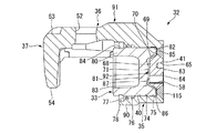
シリンダ部35のボア40の底部41には、ボア40内に突出する凸部68が形成されている。この凸部68の周囲は、ボア40の中で最も深さが深くボア40の中心線に対して直交する平面からなりボア40の中心線と同軸の円環状をなす底面69となっている。凸部68は、この底面69の内端縁部からボア40の中心線と同軸のテーパ状をなしてボア40の軸線方向に突出する円錐外面70と、円錐外面70の底面69とは反対側にあって底面69と平行をなす、ボア40の中心線と同軸の円形状の平面からなる頂面71とを有する切頭円錐状をなしている。そして、上記した流入孔58は、ボア40の軸線方向に沿って底部41の外面63から凸部68の頂面71に連通しており、凸部68の範囲内、より具体的には凸部68の頂面71の範囲内に形成されている。加えて、回止穴65も、ボア40の軸線方向に沿って底部41の外面63から形成されており、凸部68の範囲内、より具体的には凸部68の頂面71の範囲内に形成されている。   A convex portion 68 projecting into the bore 40 is formed at the bottom 41 of the bore 40 of the cylinder portion 35. The periphery of the convex portion 68 is a bottom surface 69 that is formed in a plane that is deepest in the bore 40 and orthogonal to the center line of the bore 40, and forms an annular shape that is coaxial with the center line of the bore 40. The convex portion 68 has a conical outer surface 70 that protrudes in the axial direction of the bore 40 from the inner end edge of the bottom surface 69 and is coaxial with the center line of the bore 40, and is opposite to the bottom surface 69 of the conical outer surface 70. A truncated cone shape having a top surface 71 made of a circular plane coaxial with the center line of the bore 40 and parallel to the bottom surface 69 is formed. The inflow hole 58 communicates with the top surface 71 of the convex portion 68 from the outer surface 63 of the bottom portion 41 along the axial direction of the bore 40, and more specifically within the range of the convex portion 68. It is formed within the range of 68 top surfaces 71. In addition, the anti-rotation hole 65 is also formed from the outer surface 63 of the bottom portion 41 along the axial direction of the bore 40, and is within the range of the convex portion 68, more specifically within the range of the top surface 71 of the convex portion 68. Is formed.

ボア40は、ピストン33を摺動可能に嵌合させる一定径の嵌合内径部74と、嵌合内径部74よりも底部41側であってボア40の最も底部41側にある、嵌合内径部74よりも大径の大径内径部75とを有している。また、嵌合内径部74の軸線方向における中間位置には、嵌合内径部74よりも大径で図示略のピストンシールを保持するための円環状のシール周溝76が形成されている。さらに、嵌合内径部74の軸線方向における最も底部41とは反対側には、ピストン33との間に介装される図示略のブーツの一端側を嵌合保持するための円環状のブーツ周溝77およびブーツを収容するための収容段差部78が形成されている。   The bore 40 has a fitting inner diameter portion 74 having a fixed diameter for slidably fitting the piston 33 and a fitting inner diameter portion which is closer to the bottom 41 side than the fitting inner diameter portion 74 and closest to the bottom portion 41 of the bore 40. It has a large-diameter inner diameter portion 75 that is larger in diameter than the portion 74. Further, an annular seal circumferential groove 76 having a diameter larger than that of the fitting inner diameter portion 74 and holding a piston seal (not shown) is formed at an intermediate position in the axial direction of the fitting inner diameter portion 74. Further, on the side opposite to the bottom 41 in the axial direction of the fitting inner diameter portion 74, an annular boot periphery for fitting and holding one end side of a boot (not shown) interposed between the piston 33 An accommodating stepped portion 78 for accommodating the groove 77 and the boot is formed.

ピストン33は、略円筒状の円筒状部80と、円筒状部80の軸線方向の中間位置に円筒状部80の内側を閉塞するように軸線方向一側に偏って形成された略円板状の円板状部81とを有するカップ状に形成されており、円筒状部80の外周面においてボア40の嵌合内径部74に摺動可能に嵌合する。このようにボア40に嵌合した状態でピストン33はボア40と同軸状をなす。ピストン33には、円筒状部80における円板状部81が偏った側の端部と円板状部81とで外底部82が形成されることになり、このピストン33の外底部82には、軸線方向に凹む凹部83が形成されている。また、ピストン33の外底部82とは反対側の外周面には、シリンダ部35の上記した図示略のブーツの他端側を嵌合保持するブーツ周溝84が形成されている。   The piston 33 has a substantially cylindrical shape 80 and a substantially disc-like shape formed so as to be biased to one side in the axial direction so as to close the inside of the cylindrical portion 80 at an intermediate position in the axial direction of the cylindrical portion 80. The disc-shaped portion 81 is slidably fitted to the fitting inner diameter portion 74 of the bore 40 on the outer peripheral surface of the cylindrical portion 80. The piston 33 is coaxial with the bore 40 in such a state that it is fitted to the bore 40. In the piston 33, an outer bottom portion 82 is formed by an end portion of the cylindrical portion 80 on the side where the disc-like portion 81 is biased and the disc-like portion 81, and the outer bottom portion 82 of the piston 33 is formed on the piston 33. A recess 83 that is recessed in the axial direction is formed. A boot peripheral groove 84 is formed on the outer peripheral surface of the piston 33 opposite to the outer bottom portion 82 to fit and hold the other end side of the above-described unillustrated boot of the cylinder portion 35.

ここで、ピストン33の外底部82の端面85は、ピストン33の中心線に対して直交する平面からなりピストン33の中心線と同軸の円環状をなしている。ピストン33の凹部83は、この端面85の内端縁部から軸線方向内側に、内側ほど縮径するようにピストン33の中心線と同軸のテーパ状に形成された円錐内面86と、円錐内面86の端面85とは反対側にあって中央側ほど端面85側に位置するようにピストン33の中心線と同軸の略球面状をなす球状底面87とを有している。ここで、ピストン33は端面85においてボア40の底面69に面接触で当接することになり、凹部83は、このようにピストン33が端面85においてボア40の底面69に当接した状態で、上記したボア40の底部41の凸部68を格納するようになっている。そして、この格納状態で凸部68の円錐外面70と凹部83の円錐内面86との間には全面的に隙間が形成され、凸部68の頂面71と凹部83の球状底面87との間にも全面的に隙間が形成される。   Here, the end surface 85 of the outer bottom portion 82 of the piston 33 is a plane that is orthogonal to the center line of the piston 33 and has an annular shape that is coaxial with the center line of the piston 33. The concave portion 83 of the piston 33 has a conical inner surface 86 formed in a tapered shape coaxial with the center line of the piston 33 so as to decrease in diameter toward the inner side in the axial direction from the inner end edge of the end surface 85, and a conical inner surface 86. And a spherical bottom surface 87 having a substantially spherical shape coaxial with the center line of the piston 33 so as to be located on the side opposite to the end surface 85 and closer to the end surface 85 side toward the center side. Here, the piston 33 is brought into contact with the bottom surface 69 of the bore 40 at the end face 85 by surface contact, and the recess 83 is in the state where the piston 33 is in contact with the bottom face 69 of the bore 40 at the end face 85 as described above. The convex portion 68 of the bottom 41 of the bore 40 is stored. In this stored state, a gap is entirely formed between the conical outer surface 70 of the convex portion 68 and the conical inner surface 86 of the concave portion 83, and between the top surface 71 of the convex portion 68 and the spherical bottom surface 87 of the concave portion 83. In addition, a gap is formed on the entire surface.

そして、第1実施形態においては、キャリパボディ32が、図6に示すように、爪部37と、ブリッジ部36と、シリンダ部35の底部41の一部を除いたシリンダ構成部90とからなるキャリパボディ本体91と、シリンダ部35の底部41を形成する図7に示す底蓋部材92とを摩擦攪拌接合することにより形成される。これらキャリパボディ本体91および底蓋部材92は、それぞれアルミニウム合金で個別に鋳造で一体成形されることになり、よって、これらを接合したキャリパボディ32もアルミニウム合金で形成されることになる。なお、図3に示す上記した一対のブリーダボス44も鋳造による一体成形時にキャリパボディ本体91に形成されることになる。   In the first embodiment, as shown in FIG. 6, the caliper body 32 includes a claw portion 37, a bridge portion 36, and a cylinder component 90 excluding a part of the bottom 41 of the cylinder portion 35. This is formed by friction stir welding of the caliper body main body 91 and the bottom lid member 92 shown in FIG. 7 that forms the bottom 41 of the cylinder portion 35. The caliper body main body 91 and the bottom lid member 92 are individually formed integrally by casting with an aluminum alloy, and thus the caliper body 32 to which they are joined is also formed with an aluminum alloy. The pair of bleeder bosses 44 shown in FIG. 3 are also formed on the caliper body main body 91 during integral molding by casting.

図6に示すキャリパボディ本体91には、図5に示すシリンダ部35のボア40の底面69の外径側の一部を構成する、ボア40の中心線に対し直交する平面からなりボア40と同軸の円環状をなす一定幅の底面構成面94が形成されている。また、キャリパボディ本体91には、この底面構成面94の内周縁部から、ボア40と同軸をなし一定径でボア40の軸線方向に沿って外側まで円筒面状に延出する嵌合円筒面95が形成されている。そして、嵌合円筒面95の底面構成面94とは反対側の外周縁部から外側に広がるように、図5に示す外面63の外側の一部を構成する、ボア40の中心線に対し直交する平面からなる外面構成面96が形成されている。よって、嵌合円筒面95の内側がボア40の底部41を貫通する開口部97となり、嵌合円筒面95を含むその周縁部が開口周縁部98となっている。その結果、キャリパボディ本体91に形成されるシリンダ部35のシリンダ構成部90は、有底筒状ではなく、両端が開口する無底筒状に形成されている。このキャリパボディ本体91の鋳物素材は、そのディスク回転方向の中央を基準として前後が対称の形状をなす。   The caliper body main body 91 shown in FIG. 6 has a plane that is part of the outer diameter side of the bottom surface 69 of the bore 40 of the cylinder portion 35 shown in FIG. A bottom-constituting surface 94 having a constant width and having a coaxial annular shape is formed. Further, the caliper body main body 91 has a fitting cylindrical surface that is coaxial with the bore 40 and extends from the inner peripheral edge portion of the bottom surface constituting surface 94 to the outside along the axial direction of the bore 40 with a constant diameter. 95 is formed. And it is orthogonal to the centerline of the bore 40 which comprises a part of the outer side of the outer surface 63 shown in FIG. 5 so that it may spread outside from the outer peripheral edge part on the opposite side to the bottom face constituting surface 94 of the fitting cylindrical surface 95. An outer surface constituting surface 96 made of a flat surface is formed. Therefore, the inside of the fitting cylindrical surface 95 is an opening 97 that penetrates the bottom 41 of the bore 40, and the peripheral portion including the fitting cylindrical surface 95 is an opening peripheral portion 98. As a result, the cylinder constituent portion 90 of the cylinder portion 35 formed in the caliper body main body 91 is not a bottomed cylindrical shape, but is formed in a bottomless cylindrical shape having both ends open. The casting material of the caliper body main body 91 has a symmetrical shape with respect to the center in the disk rotation direction.

図7に示す底蓋部材92は、円盤状に形成され、図8に示すようにキャリパボディ本体91のシリンダ構成部90の嵌合円筒面95に嵌合させられる。つまり、底蓋部材92は、図9に示すように、最大外径部分となる一定径の円筒面状をなす嵌合円筒面100と、この嵌合円筒面100の軸線方向の一端縁部から軸線方向に直交して内側に一定幅で形成される、図5に示すボア40の底面69の内径側の一部を構成する円環状の平面からなる底面構成面101と、この底面構成面101の内周縁部から嵌合円筒面100と同軸をなして軸線方向一側に突出するテーパ状の上記した円錐外面70と、この円錐外面70の底面構成面101とは反対側にあって底面構成面101と平行をなす上記した頂面71とを有している。また、底蓋部材92は、嵌合円筒面100の軸線方向の他端縁部から軸線方向に直交して内側に形成される円形状の平面からなる、図5に示す外面63の外側の一部を構成する外面構成面102を有している。よって、底蓋部材92は、円錐外面70および頂面71を有する凸部68が形成された一面に対して他面である外面構成面102が軸直交方向に沿う平坦面となっている。以上により、この底蓋部材92は、中心軸線を含む断面がいずれの断面においても一定形状をなしている。言い換えれば、底蓋部材92は、この断面を中心軸線を中心に回転させることにより形成される形状をなしている。よって、底蓋部材92の鋳物素材もそのディスク回転方向の中央を基準として対称の形状をなす。   The bottom lid member 92 shown in FIG. 7 is formed in a disc shape, and is fitted to the fitting cylindrical surface 95 of the cylinder component 90 of the caliper body main body 91 as shown in FIG. That is, as shown in FIG. 9, the bottom lid member 92 is formed from a fitting cylindrical surface 100 having a cylindrical surface shape having a constant diameter as a maximum outer diameter portion, and one end edge in the axial direction of the fitting cylindrical surface 100. A bottom surface forming surface 101 formed of an annular plane that forms a part on the inner diameter side of the bottom surface 69 of the bore 40 shown in FIG. The tapered outer cone surface 70 that is coaxial with the fitting cylindrical surface 100 from the inner peripheral edge portion thereof and protrudes to one side in the axial direction, and the bottom surface configuration opposite to the bottom surface constituting surface 101 of the outer cone surface 70. The top surface 71 is parallel to the surface 101. Further, the bottom cover member 92 is formed of a circular plane formed on the inner side perpendicular to the axial direction from the other end edge of the fitting cylindrical surface 100 in the axial direction. It has the outer surface constituting surface 102 which comprises a part. Therefore, in the bottom cover member 92, the outer surface constituting surface 102 which is the other surface with respect to one surface on which the convex portion 68 having the conical outer surface 70 and the top surface 71 is formed is a flat surface along the axis orthogonal direction. As described above, the bottom cover member 92 has a constant shape in any cross section including the central axis. In other words, the bottom cover member 92 has a shape formed by rotating this cross section around the central axis. Therefore, the casting material of the bottom lid member 92 also has a symmetric shape with respect to the center in the disk rotation direction.

そして、キャリパボディ32を形成する際には、アルミニウム合金で図6に示すキャリパボディ本体91を形成するための鋳物素材を一体成形する。キャリパボディ本体91の鋳物素材には、鋳造段階で、爪部37と、ブリッジ部36と、内側に下穴を有する無底筒状のシリンダ構成部90とが形成されている。そして、シリンダ構成部90内の下穴内を、嵌合円筒面95の下穴部分を介して爪部37とは反対側から挿入される切削工具により切削加工して、ボア40の内部の嵌合内径部74、シール周溝76、ブーツ周溝77、収容段差部78および嵌合円筒面95を切削する。これにより、キャリパボディ本体91には、図6に示すように、筒状に形成され両端が開口となっているシリンダ構成部90が形成されることになる。なお、大径内径部75、底面構成面94および外面構成面96は、鋳造時に形成されることになるが、これらを切削加工により形成しても良い。このようにして、アルミニウム合金の一体成形された鋳物素材を切削加工することにより形成される、シリンダ構成部90と、ディスク12を跨ぐためにシリンダ構成部90の径方向外方でその軸方向へ延びるブリッジ部36と、ブリッジ部36のシリンダ構成部90とは反対側の爪部37とを有するキャリパボディ本体91を準備する(キャリパボディ本体準備工程)。   And when forming the caliper body 32, the casting raw material for forming the caliper body main body 91 shown in FIG. 6 with an aluminum alloy is integrally molded. In the casting material of the caliper body main body 91, a claw portion 37, a bridge portion 36, and a bottomless cylindrical cylinder constituting portion 90 having a pilot hole inside are formed at the casting stage. Then, the inside of the prepared hole in the cylinder component 90 is cut by a cutting tool inserted from the opposite side of the claw portion 37 through the prepared hole portion of the fitting cylindrical surface 95, and the inside of the bore 40 is fitted. The inner diameter portion 74, the seal circumferential groove 76, the boot circumferential groove 77, the accommodation stepped portion 78, and the fitting cylindrical surface 95 are cut. As a result, as shown in FIG. 6, the caliper body main body 91 is formed with a cylinder component 90 that is formed in a cylindrical shape and has both ends opened. The large-diameter inner diameter portion 75, the bottom surface constituting surface 94, and the outer surface constituting surface 96 are formed at the time of casting, but they may be formed by cutting. In this way, the cylinder component 90 formed by cutting the cast material integrally formed of the aluminum alloy and the axially outward of the cylinder component 90 in the radial direction to straddle the disk 12 are extended. A caliper body main body 91 having the bridge portion 36 and the claw portion 37 on the opposite side of the cylinder constituting portion 90 of the bridge portion 36 is prepared (caliper body main body preparation step).

また、アルミニウム合金で一体成形された円盤状の素材から、嵌合円筒面100を切削加工することにより、図7に示すように、円盤状に形成され、一面側に凸部68が設けられた底蓋部材92を準備する(底蓋部材準備工程)。なお、底面構成面101、円錐外面70、頂面71および外面構成面102は鋳造時に形成されることになるが、これらを切削加工により形成しても良い。   Further, by cutting the fitting cylindrical surface 100 from a disk-shaped material integrally formed of an aluminum alloy, as shown in FIG. 7, a disk-shaped material is formed, and a convex portion 68 is provided on one surface side. The bottom lid member 92 is prepared (bottom lid member preparation step). The bottom surface constituting surface 101, the conical outer surface 70, the top surface 71, and the outer surface constituting surface 102 are formed at the time of casting, but they may be formed by cutting.

そして、上記のキャリパボディ本体準備工程で準備した図8に示すキャリパボディ本体91のボア40に中子治具A,Bを挿入し一体的に保持する。この状態のキャリパボディ本体91を爪部37を下側にして摩擦攪拌接合装置にセットする。続いて、上記した底蓋部材準備工程で準備した底蓋部材92を凸部68を下側にしてその嵌合円筒面100において、キャリパボディ本体91のシリンダ構成部90の嵌合円筒面95に嵌合させる。これにより、底蓋部材92はボア40内に臨む一面側に凸部68が設けられた状態になる。このとき、図示略の中子治具の同じ基準面にキャリパボディ本体91の底面構成面94と底蓋部材92の底面構成面101とが当接することになり、キャリパボディ本体91に対して底蓋部材92が、嵌合円筒部95,100同士の嵌合と合わせて位置決めされる。   Then, the core jigs A and B are inserted and held integrally in the bore 40 of the caliper body main body 91 shown in FIG. 8 prepared in the caliper body main body preparation step. The caliper body main body 91 in this state is set in the friction stir welding apparatus with the claw portion 37 facing downward. Subsequently, the bottom lid member 92 prepared in the above-described bottom lid member preparation step is arranged on the fitting cylindrical surface 95 of the cylinder constituting portion 90 of the caliper body main body 91 on the fitting cylindrical surface 100 with the convex portion 68 facing downward. Fit. As a result, the bottom lid member 92 is in a state in which the convex portion 68 is provided on one side facing the bore 40. At this time, the bottom surface constituting surface 94 of the caliper body main body 91 and the bottom surface constituting surface 101 of the bottom lid member 92 come into contact with the same reference surface of the core jig (not shown), and the bottom surface of the caliper body main body 91 is in contact with the bottom surface. The lid member 92 is positioned together with the fitting between the fitting cylindrical portions 95 and 100.

この状態で、シリンダ構成部90の底部41側を構成する、嵌合円筒面95を含む開口周縁部98に、凸部68をシリンダ構成部90の内側に配置した状態の底蓋部材92の嵌合円筒面100を含む外周縁部103を、摩擦攪拌接合により一体的に接合して、ボア40の底部41を形成する(摩擦攪拌接合工程)。   In this state, the bottom lid member 92 in a state in which the convex portion 68 is disposed on the inner side of the cylinder constituting portion 90 is formed on the opening peripheral edge portion 98 including the fitting cylindrical surface 95 constituting the bottom 41 side of the cylinder constituting portion 90. The outer peripheral edge portion 103 including the combined cylindrical surface 100 is integrally joined by friction stir welding to form the bottom 41 of the bore 40 (friction stir welding step).

ここで、この摩擦攪拌接合工程で使用される接合工具110は、円柱状の大径軸部111と、この大径軸部111よりも小径でこの大径軸部111と同軸の先端軸部112とを有しており、先細の切頭円錐状をなす先端軸部112が高速回転することにより、シリンダ構成部90の開口周縁部98および底蓋部材92の外周縁部103を摩擦により溶融させて攪拌し接合する。   Here, a welding tool 110 used in the friction stir welding process includes a cylindrical large-diameter shaft portion 111 and a tip shaft portion 112 having a smaller diameter than the large-diameter shaft portion 111 and coaxial with the large-diameter shaft portion 111. When the tip shaft 112 having a tapered truncated cone shape rotates at a high speed, the opening peripheral edge 98 of the cylinder component 90 and the outer peripheral edge 103 of the bottom cover member 92 are melted by friction. Stir and join.

上記した摩擦攪拌接合工程においては、高速回転する接合工具110の先端軸部112を、一対のブリーダボス44のうちプラグ取付穴45が形成される予定でないブリーダボス44側を開始点として、シリンダ構成部90の開口周縁部98と底蓋部材92の外周縁部103との接合境界に沿って所定方向に連続的に移動させ開口周縁部98および外周縁部103の全周に亘って円形状に摩擦攪拌接合を行うことで、底蓋部材92とキャリパボディ本体91との境界部分を一体化する。つまり、底蓋部材92とキャリパボディ本体91との境界部分に倣ってループ状の摩擦攪拌接合の接合軌跡を形成するように接合工具110を移動させる。   In the friction stir welding process described above, the front end shaft portion 112 of the welding tool 110 that rotates at a high speed starts from the bleeder boss 44 side of the pair of bleeder bosses 44 where the plug mounting holes 45 are not to be formed. Is continuously moved in a predetermined direction along the joining boundary between the opening peripheral edge 98 of the bottom cover member 92 and the outer peripheral edge 103 of the bottom cover member 92, and the friction stirring is performed in a circular shape over the entire periphery of the opening peripheral edge 98 and the outer peripheral edge 103. By joining, the boundary part of the bottom cover member 92 and the caliper body main body 91 is integrated. That is, the joining tool 110 is moved so as to form a joining locus of the loop friction stir welding following the boundary portion between the bottom lid member 92 and the caliper body main body 91.

そして、接合工具110を、これが接合開始点に近いプラグ取付穴45が形成される予定でないブリーダボス44の位置に戻ったところで、このブリーダボス44側に逃がした後、キャリパボディ32から引き抜く。その結果、接合工具110の先端軸部112により、図3に示すように、このプラグ取付穴45が形成される予定でないブリーダボス44の位置に、ボア40よりも外側に位置して残存穴部56が形成されることになる。   Then, when the joining tool 110 returns to the position of the bleeder boss 44 where the plug attachment hole 45 is not scheduled to be formed near the joining start point, the joining tool 110 escapes to the bleeder boss 44 side and is then pulled out from the caliper body 32. As a result, as shown in FIG. 3, the distal end shaft portion 112 of the joining tool 110 is positioned outside the bore 40 at the position of the bleeder boss 44 where the plug mounting hole 45 is not to be formed. Will be formed.

なお、図8に示すシリンダ構成部90の開口周縁部98と底蓋部材92の外周縁部103とは中子治具A,Bによって位置決め状態のまま摩擦攪拌接合により接合されることになり、底面構成面94と底面構成面101とで図9に示す底面69が、図8に示す外面構成面96と外面構成面102とで図9に示す外面63が形成される。摩擦攪拌接合により一端溶融状態となって一体化された後に固化する接合部115は、ボア40の中心軸線を中心とした略円環状をなし、ボア40の中心軸線を含む断面の形状が、ボア40側ほど幅が狭くなる形状をなすことになる。   In addition, the opening peripheral part 98 of the cylinder structure part 90 shown in FIG. 8 and the outer peripheral part 103 of the bottom cover member 92 will be joined by friction stir welding with the core jig | tool A and B in a positioning state, A bottom surface 69 shown in FIG. 9 is formed by the bottom surface forming surface 94 and the bottom surface forming surface 101, and an outer surface 63 shown in FIG. 9 is formed by the outer surface forming surface 96 and the outer surface forming surface 102 shown in FIG. The joint 115 that is solidified after being melted and integrated at one end by friction stir welding has a substantially annular shape centered on the central axis of the bore 40, and the cross-sectional shape including the central axis of the bore 40 has a bore shape. The shape becomes narrower toward the 40th side.

上記の摩擦攪拌接合工程で接合されたキャリパボディ本体91および底蓋部材92からなるキャリパボディ32には、ボア40の底面69よりもボア40の内部側に突出する凸部68が形成されている。言い換えれば、図9に示す外面63から底面69までの厚さt1よりも外面63から凸部68のボア40の内部側の端面である頂面71までの厚さt2の方が厚くなっている。   The caliper body 32 composed of the caliper body main body 91 and the bottom lid member 92 joined in the friction stir welding process is formed with a convex portion 68 that protrudes further to the inner side of the bore 40 than the bottom surface 69 of the bore 40. . In other words, the thickness t2 from the outer surface 63 to the top surface 71 that is the inner end face of the bore 40 of the convex portion 68 is thicker than the thickness t1 from the outer surface 63 to the bottom surface 69 shown in FIG. .

上記した摩擦攪拌接合工程で接合されたキャリパボディ本体91および底蓋部材92からなるキャリパボディ32に対して、底蓋部材92で構成されるそのシリンダ部35の底部41に、図9に示すように、上記したボア40に液圧を供給するための流入孔58と、座ぐり64と、回止穴65とを外側から穿設する(流入孔等穿設工程)。つまり、図3に示すようにキャリパボディ32のディスク回転方向における中央を通るディスク半径線上であって、ボア40の中心よりもディスク半径方向内側にずれた位置に、図9に示すように凸部68の範囲内で、凸部68が形成された一面を構成する頂面71と他面を構成する外面63とを連通するようにネジ孔からなる流入孔58を切削加工するとともに、これと同軸に座ぐり64を切削加工する。合わせて、図3に示すように、キャリパボディ32のディスク回転方向における中央を通るディスク半径線上であって、ボア40の中心よりもディスク半径方向外側にずれた位置に回止穴65を、図9に示すように途中位置まで穿設する。加えて、図3に示すように、一対のブリーダボス44のうち取付方向に応じて決まるブリーダプラグ43(図1参照)の取付側のブリーダボス44に、その突出方向に沿ってプラグ取付穴45およびブリーダ連通穴55を穿設してボア40を径方向外側に連通させる。なお、プラグ取付穴45およびブリーダ連通穴55は、上記したキャリパボディ本体準備工程において形成しても良い。   As shown in FIG. 9, the caliper body 32 composed of the caliper body main body 91 and the bottom lid member 92 joined in the friction stir welding process described above is formed on the bottom 41 of the cylinder portion 35 constituted by the bottom lid member 92. In addition, an inflow hole 58 for supplying hydraulic pressure to the above-described bore 40, a counterbore 64, and a rotation stop hole 65 are drilled from the outside (a process of drilling an inflow hole or the like). That is, as shown in FIG. 9, the convex portion is located on the disk radial line passing through the center of the caliper body 32 in the disk rotation direction as shown in FIG. In the range of 68, the inflow hole 58 formed of a screw hole is cut so as to communicate with the top surface 71 constituting one surface on which the convex portion 68 is formed and the outer surface 63 constituting the other surface, and is coaxial with this. The counterbore 64 is cut. In addition, as shown in FIG. 3, a rotation hole 65 is located at a position on the disk radial line passing through the center of the caliper body 32 in the disk rotation direction and shifted outward from the center of the bore 40 in the disk radial direction. As shown in FIG. In addition, as shown in FIG. 3, the plug mounting hole 45 and the bleeder 44 are formed along the protruding direction of the bleeder boss 44 on the mounting side of the bleeder plug 43 (see FIG. 1) determined according to the mounting direction of the pair of bleeder bosses 44. A communication hole 55 is formed to allow the bore 40 to communicate radially outward. Note that the plug attachment hole 45 and the bleeder communication hole 55 may be formed in the caliper body main body preparation step.

以上のように形成された図10に示すキャリパボディ32に対して、爪部37とシリンダ部35との間から、シール周溝76に図示略のピストンシールを嵌合し、ブーツ周溝77にブーツをの一端側を嵌合して、同じく爪部37とシリンダ部35との間から、ピストン33をボア40内に嵌合し、ブーツの他端側をブーツ周溝84に嵌合する。また、プラグ取付穴45に図1に示すブリーダプラグ43を取り付ける。このようにして、キャリパ15が組み上がる。   With the caliper body 32 shown in FIG. 10 formed as described above, a piston seal (not shown) is fitted in the seal circumferential groove 76 from between the claw portion 37 and the cylinder portion 35, and the boot circumferential groove 77 is fitted. One end side of the boot is fitted, the piston 33 is fitted into the bore 40 from between the claw portion 37 and the cylinder portion 35, and the other end side of the boot is fitted into the boot circumferential groove 84. Further, the bleeder plug 43 shown in FIG. In this way, the caliper 15 is assembled.

このようにして組み上がったキャリパ15に、図5に示すように、配管60を取り付ける。つまり、回止穴65に、配管60の口金61に固定された屈曲形状の回止フック66を係合させた状態で、ユニオンボルト62を口金61に挿入しつつ流入孔58に螺合させる。すると、回止フック66および回止穴65で回り止めされた状態で配管60の口金61がユニオンボルト62とともにキャリパ15に固定され、ボア40内に配管60が連通する。なお、このとき、口金61は座ぐり64に当接することになり流入孔58に対する垂直度を確保する。   A pipe 60 is attached to the caliper 15 assembled in this way, as shown in FIG. That is, the union bolt 62 is screwed into the inflow hole 58 while the union bolt 62 is inserted into the base 61 in a state in which the bent-shaped stop hook 66 fixed to the base 61 of the pipe 60 is engaged with the stop hole 65. Then, the base 61 of the pipe 60 is fixed to the caliper 15 together with the union bolt 62 in a state of being prevented from rotating by the stop hook 66 and the stop hole 65, and the pipe 60 communicates with the bore 40. At this time, the base 61 comes into contact with the counterbore 64 and secures the perpendicularity to the inflow hole 58.

そして、キャリパ15を車両へ装着し、真空引きにてブレーキフルードをキャリパボディ32のボア40内に充填する。このとき、真空引きの負圧で、ピストン33がボア40の内方に引っ張られ、その端面85がボア40の底面69に当接することになるが、この状態でも、ボア40の底部41の凸部68を格納するピストン33の凹部83が凸部68に対して隙間をもっているため、ピストン33のボア40の底部41への張り付きが規制される。   Then, the caliper 15 is mounted on the vehicle, and the brake fluid is filled into the bore 40 of the caliper body 32 by evacuation. At this time, the piston 33 is pulled inwardly of the bore 40 by the negative pressure of vacuuming, and the end surface 85 abuts against the bottom surface 69 of the bore 40. Even in this state, the convexity of the bottom 41 of the bore 40 is raised. Since the concave portion 83 of the piston 33 that stores the portion 68 has a gap with respect to the convex portion 68, the sticking of the piston 33 to the bottom portion 41 of the bore 40 is restricted.

ここで、上記した特許文献1のディスクブレーキでは、ボアを形成するシリンダ部が筒状に形成されるとともに、シリンダ部の底部側に設けられた開口周縁部とこの開口周縁部に嵌合される底蓋部材とを摩擦攪拌接合により一体に接合することでボアの底部を形成するようになっているが、主に二輪車用のものであるため、ボアに液圧を供給する流入孔はキャリパのディスク半径方向外側に設けられている。これに対して、一般に四輪自動車用のディスクブレーキでは、流入孔をボアの底部に形成するようになっている。このように流入孔をボアの底部に形成するものであると、流入孔を形成するためのボス部(突起)が底部の外面に形成されることになるため、この部分が摩擦攪拌接合の接合工具に当たる可能性があり、摩擦攪拌接合が困難で、製造効率が低下する可能性があった。   Here, in the above-described disc brake of Patent Document 1, the cylinder portion that forms the bore is formed in a cylindrical shape, and is fitted to the opening peripheral portion provided on the bottom side of the cylinder portion and the opening peripheral portion. The bottom part of the bore is formed by integrally joining the bottom lid member by friction stir welding, but since it is mainly for motorcycles, the inflow hole for supplying hydraulic pressure to the bore has a caliper. It is provided on the outer side in the disk radial direction. On the other hand, in general, in a disc brake for a four-wheeled vehicle, an inflow hole is formed at the bottom of the bore. If the inflow hole is formed at the bottom of the bore in this way, a boss (projection) for forming the inflow hole is formed on the outer surface of the bottom, so this part is joined by friction stir welding. There is a possibility of hitting the tool, friction stir welding is difficult, and the production efficiency may be reduced.

これに対して、第1実施形態のディスクブレーキ11によれば、底蓋部材92が、円盤状に形成され、ボア40内に臨む一面側に凸部68が設けられるとともに、ボア40に液圧を供給するための流入孔58が凸部68の範囲内で一面側の頂面71と他面である外面63とを連通して設けられているため、流入孔58を形成するための凸部68がボア40内に形成されることになり、ボア40の外側から接合工具110で行われる摩擦攪拌接合が容易となり、キャリパ15の製造効率を向上させることができる。   On the other hand, according to the disc brake 11 of the first embodiment, the bottom cover member 92 is formed in a disc shape, the convex portion 68 is provided on one side facing the bore 40, and the bore 40 is hydraulically pressurized. Since the inflow hole 58 for supplying water is provided in communication with the top surface 71 on the one surface side and the outer surface 63 which is the other surface within the range of the convex portion 68, the convex portion for forming the inflow hole 58 is provided. As a result, the friction stir welding performed by the welding tool 110 from the outside of the bore 40 is facilitated, and the manufacturing efficiency of the caliper 15 can be improved.

また、ボア40に形成された凸部68の範囲内で流入孔58を形成すれば良いため、流入孔58の位置つまり配管60の配置を含む取り回しの自由度を向上できる。   Further, since the inflow hole 58 may be formed within the range of the convex portion 68 formed in the bore 40, the degree of freedom in handling including the position of the inflow hole 58, that is, the arrangement of the pipe 60, can be improved.

また、爪部37とシリンダ部35とを接続するブリッジ部36がディスク12を跨いで設けられるフィスト型(フローティング型)のキャリパ15のキャリパボディ32であって、爪部37におけるシリンダ部35のボア40が対向する部分は、シリンダ部35の中心を覆うように形成されているため、爪部37の強度や剛性を向上することができる。これにより、爪部37の剛性不足によるブレーキ鳴きの発生を抑制することができ、ディスクブレーキの信頼性が向上する。   The bridge portion 36 that connects the claw portion 37 and the cylinder portion 35 is the caliper body 32 of the fist type (floating type) caliper 15 provided across the disk 12, and the bore of the cylinder portion 35 in the claw portion 37 is provided. Since the part where 40 opposes is formed so that the center of the cylinder part 35 may be covered, the intensity | strength and rigidity of the nail | claw part 37 can be improved. As a result, the occurrence of brake squeal due to insufficient rigidity of the claw portion 37 can be suppressed, and the reliability of the disc brake is improved.

また、爪部37側からボア40内を加工するのではなく、シリンダ部35の底部41側からボア40内を切削加工することができるため、切削工具の固定部から先端までのオーバーハングを短くすることができ、加工精度を確保した上で加工時間を短縮することができる。   Further, since the inside of the bore 40 can be cut from the bottom 41 side of the cylinder part 35 instead of machining the inside of the bore 40 from the claw part 37 side, the overhang from the fixing part to the tip of the cutting tool is shortened. Thus, the machining time can be shortened while ensuring the machining accuracy.

また、左右の取付勝手の違いに対しても共通の鋳物素材を用いることで、シリンダ部35に一対のブリーダボス44が外方に突設されることになるが、底部41を形成する際の摩擦攪拌接合の終了位置を、一対のブリーダボス44のうち、ブリーダプラグ43が配設されないブリーダボス44に設定したため、残存穴部56をボア40およびボア40に連通するブリーダ連通穴55およびプラグ取付穴45から離すことができる。よって、残存穴部56により薄肉部分が生じるのを防止することができる。また、摩擦攪拌接合の終了位置のための専用部位をキャリパ15に形成する必要がないため、キャリパ15の軽量化、ひいてはディスクブレーキの軽量化を図ることができる。   In addition, a pair of bleeder bosses 44 are projected outwardly from the cylinder portion 35 by using a common casting material for the difference between right and left mounting conveniences, but friction when the bottom portion 41 is formed. Since the end position of the stir welding is set to the bleeder boss 44 in which the bleeder plug 43 is not disposed in the pair of bleeder bosses 44, the remaining hole portion 56 is connected to the bore 40 and the bleeder communication hole 55 and the plug mounting hole 45 communicating with the bore 40. Can be released. Therefore, it is possible to prevent a thin portion from being generated by the remaining hole portion 56. In addition, since it is not necessary to form a dedicated portion for the end position of the friction stir welding in the caliper 15, it is possible to reduce the weight of the caliper 15 and hence the weight of the disc brake.

また、底蓋部材92は、外面63を構成する他面である外面構成面102が平坦となっているため、ボア40の外側から接合工具110で行われる摩擦攪拌接合がさらに容易となり、キャリパ15の製造効率をさらに向上させることができる。加えて、外面63の全体が平坦となっているため、摩擦攪拌接合が一層容易となり、キャリパ15の製造効率を一層向上させることができる。   Further, since the bottom cover member 92 has a flat outer surface constituting surface 102 which is the other surface constituting the outer surface 63, the friction stir welding performed by the welding tool 110 from the outside of the bore 40 is further facilitated, and the caliper 15 The production efficiency can be further improved. In addition, since the entire outer surface 63 is flat, friction stir welding is further facilitated, and the manufacturing efficiency of the caliper 15 can be further improved.

また、キャリパボディ32が、アルミニウム合金で形成されているため、摩擦攪拌接合がさらに容易となり、キャリパ15の製造効率をさらに向上させることができる。また、キャリパ15を軽量化することができる。   Further, since the caliper body 32 is formed of an aluminum alloy, friction stir welding is further facilitated, and the manufacturing efficiency of the caliper 15 can be further improved. Further, the caliper 15 can be reduced in weight.

また、ピストン33が、カップ状に形成されるとともに、外底部82に凸部68を格納する凹部83が形成されているため、ボア40の底部41に凸部68があっても、シリンダ部35の軸線方向長さひいてはキャリパ15の軸線方向長さが長大化することを抑制することができる。したがって、ディスクブレーキの小型化を図ることが可能となる。   In addition, since the piston 33 is formed in a cup shape and the concave portion 83 for storing the convex portion 68 is formed in the outer bottom portion 82, the cylinder portion 35 is provided even if the convex portion 68 is present in the bottom portion 41 of the bore 40. Thus, the length of the caliper 15 in the axial direction can be prevented from increasing. Therefore, it is possible to reduce the size of the disc brake.

また、底蓋部材92の流入孔58が、底蓋部材92の中心からずれているため、流入孔58を底蓋部材92の中心からずらすことにより、回止穴65を底蓋部材92の中心寄りに形成することができ、これらが形成される凸部68の径(図9のL寸法)を小さくすることができる。よって、摩擦攪拌接合時に中子治具で支持される底面構成面101を広くでき、支持剛性を確保できるので、摩擦攪拌接合の品質を安定させることができる。しかも、シリンダ部35の鋳物外径部を大きく膨らまして設定する必要がなくなるので、質量増を抑制できる。したがって、ディスクブレーキの軽量化を図ることができる。   Further, since the inflow hole 58 of the bottom cover member 92 is shifted from the center of the bottom cover member 92, the stop hole 65 is made to be the center of the bottom cover member 92 by shifting the inflow hole 58 from the center of the bottom cover member 92. They can be formed closer to each other, and the diameter (L dimension in FIG. 9) of the convex portions 68 on which these are formed can be reduced. Therefore, the bottom surface constituting surface 101 supported by the core jig at the time of friction stir welding can be widened and the support rigidity can be ensured, so that the quality of the friction stir welding can be stabilized. In addition, since it is not necessary to set the outer diameter portion of the casting of the cylinder portion 35 so as to be greatly expanded, an increase in mass can be suppressed. Therefore, the weight of the disc brake can be reduced.

第1実施形態のディスクブレーキ11の製造方法によれば、ボア40の内部を切削加工されて筒状に形成され両端が開口となっているシリンダ部35と、ディスク12を跨ぐためにシリンダ部35の径方向外方でその軸方向へ延びるブリッジ部36とを有するキャリパボディ本体91を準備する工程と、円盤状に形成され、一面側に凸部68が設けられる底蓋部材92を準備する工程と、シリンダ部35の底部41側の開口周縁部98に、凸部68をシリンダ部35の内側に配置した状態で底蓋部材92を摩擦攪拌接合により一体的に接合する工程と、キャリパボディ本体91に接合された底蓋部材92に、凸部68の範囲内で一面側の頂面71と他面である外面63とを連通する流入孔58を切削加工する工程とからなるため、流入孔58を形成するための凸部68がボア40内に形成されることになり、ボア40の外側から接合工具110で行われる摩擦攪拌接合が容易となり、キャリパ15の製造効率を向上させることができる。   According to the manufacturing method of the disc brake 11 of the first embodiment, the inside of the bore 40 is cut and formed into a cylindrical shape, and both ends of the cylinder portion 35 are opened. A step of preparing a caliper body main body 91 having a bridge portion 36 extending radially outward in the axial direction; a step of preparing a bottom lid member 92 formed in a disk shape and provided with a convex portion 68 on one surface side; A step of integrally joining the bottom lid member 92 to the opening peripheral edge portion 98 on the bottom 41 side of the cylinder portion 35 by friction stir welding in a state where the convex portion 68 is disposed inside the cylinder portion 35, and a caliper body main body 91. The bottom cover member 92 joined to the base plate member 92 includes a step of cutting the inflow hole 58 that connects the top surface 71 on the one surface side and the outer surface 63 that is the other surface within the range of the convex portion 68. Projection 68 for forming is to be formed in the bore 40, friction stir welding is facilitated to be performed by the welding tool 110 from the outside of the bore 40, thereby improving the manufacturing efficiency of the caliper 15.

また、シリンダ部35に底蓋部材92を摩擦攪拌接合により一体的に接合する工程の後、凸部68の範囲内で一面側の頂面71と他面である外面63とを連通する流入孔58を切削加工する工程を行うため、摩擦攪拌接合時に底蓋部材92のシリンダ部35に対する回転方向の位置決めが不要となり、摩擦攪拌接合がさらに容易となって、キャリパ15の製造効率をさらに向上することができる。   In addition, after the step of integrally joining the bottom cover member 92 to the cylinder portion 35 by friction stir welding, an inflow hole that communicates the top surface 71 on the one surface side with the outer surface 63 that is the other surface within the range of the convex portion 68. Since the step of cutting 58 is performed, positioning of the bottom cover member 92 in the rotational direction with respect to the cylinder portion 35 is not required at the time of friction stir welding, and friction stir welding is further facilitated, and the manufacturing efficiency of the caliper 15 is further improved. be able to.

加えて、シリンダ部35に底蓋部材92を摩擦攪拌接合により一体的に接合する工程の後に、配管60の口金61のシート面を形成する座ぐり64も行うため、座ぐり64に傷や圧痕を付けてしまうことを防止できる。つまり、底蓋部材92をキャリパボディ本体91にセットしたり、摩擦攪拌接合したり、接合後にキャリパボディ32を摩擦攪拌接合装置から取り外したりする際等に傷や圧痕を付け易いが、これを防止できることになる。   In addition, a counterbore 64 that forms the seat surface of the base 61 of the pipe 60 is also performed after the step of integrally joining the bottom lid member 92 to the cylinder portion 35 by friction stir welding. Can be prevented. That is, it is easy to make a scratch or an indentation when the bottom lid member 92 is set on the caliper body main body 91, friction stir welding is performed, or the caliper body 32 is removed from the friction stir welding apparatus after joining, but this is prevented. It will be possible.

「第2実施形態」
次に、第2実施形態を主に図11に基づいて第1実施形態との相違部分を中心に説明する。
“Second Embodiment”
Next, the second embodiment will be described mainly on the basis of FIG. 11 with a focus on differences from the first embodiment.

図11は、本発明に係る第2実施形態のディスクブレーキのキャリパボディおよびピストンを示す断面図である。なお、第1実施形態と共通する部位については、同一称呼、同一の符号で表す。   FIG. 11 is a cross-sectional view showing a caliper body and a piston of a disc brake according to a second embodiment of the present invention. In addition, about the site | part which is common in 1st Embodiment, it represents with the same name and the same code | symbol.

第2実施形態においては、底蓋部材92の形状が第1実施形態と相違している。つまり、第2実施形態では、底蓋部材92に、ボア40内に突出する凸部68に加えてボア40外に突出する凸部120が形成されており、凸部120の分、凸部68の突出高さが小さくなっている。その結果、シリンダ部35のボア40の底部41に、ディスク軸線方向両側に凸部68および凸部120が形成されている。   In the second embodiment, the shape of the bottom cover member 92 is different from that of the first embodiment. In other words, in the second embodiment, the bottom cover member 92 is formed with a convex portion 120 that protrudes outside the bore 40 in addition to the convex portion 68 that protrudes into the bore 40. The protruding height of is small. As a result, a convex portion 68 and a convex portion 120 are formed on the bottom 41 of the bore 40 of the cylinder portion 35 on both sides in the disk axial direction.

凸部68は、頂面71と底面69との間に、円錐外面ではなく、頂面71側ほど小径となるように断面円弧状に湾曲する湾曲面121が形成されている。   In the convex portion 68, a curved surface 121 that is curved in a circular arc shape is formed between the top surface 71 and the bottom surface 69 so as to have a smaller diameter toward the top surface 71 side instead of the conical outer surface.

凸部120は、ボア40の軸線方向に直交する平坦な頂面123と、頂面123側ほど小径となるように断面円弧状に湾曲する湾曲面124とを有しており、底蓋部材92の湾曲面124の周囲が、頂面123と平行な平坦面で円環状をなす外面構成面102となっている。   The convex portion 120 has a flat top surface 123 that is orthogonal to the axial direction of the bore 40 and a curved surface 124 that is curved in a circular arc shape so as to have a smaller diameter toward the top surface 123 side. The curved surface 124 is surrounded by a flat surface parallel to the top surface 123 to form an outer surface constituting surface 102 having an annular shape.

そして、凸部68および凸部120は、同軸同径となっており、これらの範囲内に、第1実施形態と同様の流入孔58、座ぐり64および回止穴65が形成されている。   And the convex part 68 and the convex part 120 have the same coaxial diameter, and the inflow hole 58, the counterbore 64, and the stop hole 65 similar to 1st Embodiment are formed in these ranges.

ここで、凸部120は、摩擦攪拌接合の接合工具110との干渉を避ける形状に形成されている。   Here, the convex part 120 is formed in the shape which avoids interference with the joining tool 110 of friction stir welding.

以上に述べた第2実施形態によれば、ボア40の底部41に、ボア40内に突出する凸部68に加えてボア40外に突出する凸部120が形成されているため、ボア40内に突出する凸部68の突出高さを低くできる。よって、ブレーキフルードをその分だけ多くボア40内に充填することができ、制動時のブレーキフルードの温度上昇を抑制することができる。   According to the second embodiment described above, the bottom portion 41 of the bore 40 is formed with the convex portion 120 projecting out of the bore 40 in addition to the convex portion 68 projecting into the bore 40. The protruding height of the protruding portion 68 protruding in the direction can be reduced. Therefore, the brake fluid can be filled in the bore 40 by that much, and the temperature increase of the brake fluid during braking can be suppressed.

なお、凸部68および凸部120の突出高さを同等に設定すれば、底蓋部材92が表裏対称形状になり、キャリパボディ本体91への摩擦攪拌接合時に表裏を確認する必要がなくなるため、キャリパ15の製造効率をさらに向上させることができる。   In addition, if the protruding heights of the convex portion 68 and the convex portion 120 are set to be equal, the bottom lid member 92 has a front and back symmetrical shape, and it is not necessary to check the front and back surfaces during friction stir welding to the caliper body main body 91. The manufacturing efficiency of the caliper 15 can be further improved.

「第3実施形態」
次に、第3実施形態を主に図12〜図14に基づいて第1実施形態との相違部分を中心に説明する。なお、第1実施形態と共通する部位については、同一称呼、同一の符号で表す。
“Third Embodiment”
Next, the third embodiment will be described mainly based on FIGS. 12 to 14 with a focus on differences from the first embodiment. In addition, about the site | part which is common in 1st Embodiment, it represents with the same name and the same code | symbol.

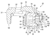
第3実施形態は、第1実施形態の配管60の回止フック66および回止穴65が設けられていない。そして、シリンダ部35のボア40の底部41には、ボア40の径方向内側であってボア40の中心からずれた位置に、第1実施形態と同様の流入孔58および座ぐり64がディスク軸線方向に沿って貫通形成されている。第3実施形態では、流入孔58が、図14に示すように、キャリパボディ32のディスク回転方向における中央を通るディスク半径線上であって、ボア40の中心よりもディスク半径方向外側(ブリッジ部36側)に全体としてずれて形成されている。   In the third embodiment, the rotation hook 66 and the rotation hole 65 of the pipe 60 of the first embodiment are not provided. The bottom 41 of the bore 40 of the cylinder portion 35 has an inflow hole 58 and a counterbore 64 similar to those of the first embodiment at a position that is radially inward of the bore 40 and shifted from the center of the bore 40. A penetration is formed along the direction. In the third embodiment, as shown in FIG. 14, the inflow hole 58 is on a disk radial line passing through the center of the caliper body 32 in the disk rotation direction and outside the center of the bore 40 in the disk radial direction (the bridge portion 36. Side) as a whole.

また、シリンダ部35のボア40の底部41には、ボア40の径方向内側であってボア40の中心からずれた位置に、一対の回止ピン取付穴130がディスク軸線方向に沿って外側から途中位置まで形成されている。一対の回止ピン取付穴130は、互いを結んだ線の中心が、キャリパボディ32のディスク回転方向における中央を通るディスク半径線上であって、ボア40の中心よりもディスク半径方向内側に全体としてずれて形成されている。この一対の回止ピン取付穴130には、図13に示す一対の平行なピン部132と、一対のピン部132を連結する連結部133とを有するH字状の回止ピン134が、一対のピン部132の連結部133より一側において圧入される。この回止ピン134は、一対のピン部132の連結部133より他側が底部41からボア40の軸線方向に沿って外側にディスク回転方向に並んで突出することになり、これらの間に配管60を挿通させることで、ユニオンボルト62の流入孔58への螺合時における口金61の連れ回りを規制する。   A pair of locking pin mounting holes 130 are formed on the bottom 41 of the bore 40 of the cylinder portion 35 from the outside along the disk axial direction at a position that is radially inward of the bore 40 and shifted from the center of the bore 40. It is formed up to the middle position. The pair of rotation-pin mounting holes 130 has a center of a line connecting each other on a disk radial line passing through the center of the caliper body 32 in the disk rotation direction, and is entirely inside the disk radial direction from the center of the bore 40. They are offset. In the pair of stop pin mounting holes 130, a pair of H-shaped stop pins 134 having a pair of parallel pin portions 132 shown in FIG. 13 and a connecting portion 133 connecting the pair of pin portions 132 are provided. The pin portion 132 is press-fitted on one side from the connecting portion 133. The other side of the locking pin 134 from the connecting portion 133 of the pair of pin portions 132 protrudes from the bottom portion 41 along the axial direction of the bore 40 to the outside in the disk rotation direction. , The rotation of the base 61 when the union bolt 62 is screwed into the inflow hole 58 is restricted.

なお、第3実施形態の流入孔58も、底部41の外面63と凸部68の頂面71とを連通しており、凸部68の範囲内に形成されている。加えて、一対の回止ピン取付穴130も凸部68の範囲内に形成されている。   In addition, the inflow hole 58 of the third embodiment also connects the outer surface 63 of the bottom portion 41 and the top surface 71 of the convex portion 68 and is formed within the range of the convex portion 68. In addition, a pair of stop pin mounting holes 130 are also formed within the range of the convex portion 68.

「第4実施形態」
次に、第4実施形態を主に図15に基づいて第1実施形態との相違部分を中心に説明する。
“Fourth Embodiment”
Next, the fourth embodiment will be described mainly based on FIG. 15 with a focus on the differences from the first embodiment.

図15は、本発明に係る第4実施形態のディスクブレーキのキャリパボディ、ピストンおよび配管類を示す断面図である。なお、第1実施形態と共通する部位については、同一称呼、同一の符号で表す。   FIG. 15 is a cross-sectional view showing a caliper body, a piston, and piping of a disc brake according to a fourth embodiment of the present invention. In addition, about the site | part which is common in 1st Embodiment, it represents with the same name and the same code | symbol.

第4実施形態では、ピストン33の球状底面87の中央部に当接凸部140が、ピストン33の軸線方向に沿って突出している。そして、この当接凸部140において、シリンダ部35のボア40の底部41に当接する。具体的には、底部41の凸部68の頂面71における流入孔58と重ならない位置に当接する。   In the fourth embodiment, the contact convex portion 140 projects along the axial direction of the piston 33 at the central portion of the spherical bottom surface 87 of the piston 33. The abutment convex portion 140 abuts the bottom 41 of the bore 40 of the cylinder portion 35. Specifically, it abuts on the top surface 71 of the convex portion 68 of the bottom portion 41 at a position that does not overlap the inflow hole 58.

ここで、ピストン33が当接凸部140において、シリンダ部35のボア40の底部41に当接した状態で、ピストンの凹部83は底部41の凸部68を格納するようになっており、このとき、ピストン33の端面85はボア40の底面69に対し離間している。この状態で、凸部68の円錐外面70と凹部83の円錐内面86との間には全面的に隙間が形成され、凸部68の頂面71と凹部83の球状底面87との間にも当接凸部140以外には隙間が形成される。   Here, in the state in which the piston 33 is in contact with the bottom 41 of the bore 40 of the cylinder part 35 in the contact convex part 140, the concave part 83 of the piston stores the convex part 68 of the bottom part 41. At this time, the end surface 85 of the piston 33 is separated from the bottom surface 69 of the bore 40. In this state, a gap is entirely formed between the conical outer surface 70 of the convex portion 68 and the conical inner surface 86 of the concave portion 83, and also between the top surface 71 of the convex portion 68 and the spherical bottom surface 87 of the concave portion 83. A gap is formed other than the contact convex portion 140.

以上に述べた第4実施形態のディスクブレーキ11によれば、キャリパボディ32を車両へ装着し、真空引きにてブレーキフルードをキャリパボディ32のボア40内に充填する際に、真空引きの負圧でシリンダ部35の底部41にピストン33が当接することになるが、ピストン33は、中央部に設けられた当接凸部140において底部41に当接することから、底部41への張り付きを防止することができる。また、ピストン33を樹脂製とした場合に、真空引き時の衝突の衝撃でピストン33の外底部82に生じる損傷を防止できる。   According to the disc brake 11 of the fourth embodiment described above, when the caliper body 32 is mounted on the vehicle and the brake fluid is filled in the bore 40 of the caliper body 32 by vacuuming, the negative pressure of vacuuming is reduced. Thus, the piston 33 comes into contact with the bottom 41 of the cylinder part 35. However, the piston 33 comes into contact with the bottom 41 at the contact convex part 140 provided at the center part, so that sticking to the bottom 41 is prevented. be able to. Further, when the piston 33 is made of resin, it is possible to prevent damage caused to the outer bottom portion 82 of the piston 33 due to the impact of collision during evacuation.

また、真空引きにてブレーキフルードをキャリパボディ32のボア40内に充填する際に、ピストン33は、当接凸部140において、底部41のうち凸部68が形成された厚肉部分に当接することになるため、衝突の衝撃で底部41に生じる損傷を防止できる。   Further, when the brake fluid is filled into the bore 40 of the caliper body 32 by evacuation, the piston 33 abuts the thick portion of the bottom 41 where the convex portion 68 is formed in the abutting convex portion 140. As a result, damage to the bottom 41 due to the impact of the collision can be prevented.

なお、以上の第1〜第4実施形態においては、シリンダ部35がディスク12の一面側のみに配置され、ディスク12の他面側には爪部37が形成され、液圧によりディスク12の一面側のみに設けられた1つのピストン33でブレーキパッド14を押圧するフィスト型のキャリパ15を例にとり説明したが、シリンダ部35がディスク12の両面側に配置される対向型のキャリパにも適用可能である。このように対向型のキャリパに適用する場合には、対向する一対のシリンダ部のうち流入孔が設けられる側のシリンダ部に摩擦攪拌接合を適用すればよく、必要があれば、両側のシリンダ部に摩擦攪拌接合を適用してもよい。また、ディスク12の一面側に2つ以上のピストンを設けたフィスト型のキャリパや対向型のキャリパにも適用可能である。さらに、第1〜第4実施形態においては、ディスク12の両面側に一対のブレーキパッド14を設けるようにしているが、二対又はそれ以上の対のブレーキパッドを設けたディスクブレーキにも適用が可能である。   In the first to fourth embodiments described above, the cylinder portion 35 is disposed only on one surface side of the disk 12, and a claw portion 37 is formed on the other surface side of the disk 12. The fist-type caliper 15 that presses the brake pad 14 with one piston 33 provided only on the side has been described as an example, but it can also be applied to a counter-type caliper in which the cylinder portion 35 is disposed on both sides of the disk 12. It is. In this way, when applied to the opposed caliper, friction stir welding may be applied to the cylinder portion on the side where the inflow hole is provided in the pair of opposed cylinder portions, and if necessary, the cylinder portions on both sides. Friction stir welding may be applied. Further, the present invention can also be applied to a fist type caliper provided with two or more pistons on one surface side of the disk 12 or a counter type caliper. Furthermore, in the first to fourth embodiments, a pair of brake pads 14 are provided on both sides of the disk 12, but the present invention can also be applied to a disk brake provided with two or more pairs of brake pads. Is possible.

上記実施の形態のディスクブレーキによれば、ディスクの両面に配置された一対のブレーキパッドのうち、少なくとも一方側のブレーキパッドを液圧により押圧するピストンが挿入されるボアが内部に形成されるシリンダ部を有するキャリパボディを備え、前記シリンダ部は、筒状に形成されるとともに、底部側に設けられた開口周縁部と該開口周縁部に嵌合される底蓋部材とを摩擦攪拌接合により一体に接合することで前記ボアの底部が形成され、前記底蓋部材は、円盤状に形成され、前記ボア内に臨む一面側に凸部が設けられるとともに、前記ボアに液圧を供給するための流入孔が前記凸部の範囲内で前記一面と他面とを連通して設けられるようになっている。これにより、ボアの外側から接合工具で行われる摩擦攪拌接合が容易となり、ディスクブレーキの製造効率を向上させることができる。   According to the disc brake of the above-described embodiment, a cylinder in which a bore into which a piston for pressing at least one of the brake pads arranged on both sides of the disc with hydraulic pressure is inserted is formed inside. The cylinder part is formed in a cylindrical shape, and an opening peripheral part provided on the bottom side and a bottom lid member fitted to the opening peripheral part are integrated by friction stir welding The bottom portion of the bore is formed by joining to the bore, and the bottom cover member is formed in a disk shape, provided with a convex portion on one side facing the bore, and for supplying hydraulic pressure to the bore An inflow hole is provided in communication with the one surface and the other surface within the range of the convex portion. Thereby, the friction stir welding performed by the welding tool from the outside of the bore is facilitated, and the manufacturing efficiency of the disc brake can be improved.

上記実施の形態のディスクブレーキによれば、キャリパボディは、前記ディスクの一方の面側に前記シリンダ部が設けられ、前記ディスクの他方の面側に爪部が設けられ、該爪部と前記シリンダ部とを接続するブリッジ部が前記ディスクを跨いで設けられるフィスト型キャリパのキャリパボディであって、前記爪部における前記シリンダ部の前記ボアが対向する部分は、前記シリンダ部の中心を覆うように形成されている。これにより、爪部の強度や剛性を向上することができ、爪部の剛性不足によるブレーキ鳴きの発生を抑制することができてディスクブレーキの信頼性が向上する。   According to the disc brake of the above embodiment, the caliper body has the cylinder portion provided on one surface side of the disc and the claw portion provided on the other surface side of the disc. The claw portion and the cylinder And a caliper body of a fist type caliper provided across the disk, and a portion of the claw portion facing the bore of the cylinder portion covers a center of the cylinder portion. Is formed. Thereby, the strength and rigidity of the claw portion can be improved, the occurrence of brake squeal due to insufficient rigidity of the claw portion can be suppressed, and the reliability of the disc brake is improved.

上記実施の形態のディスクブレーキによれば、シリンダ部は、底部の外周側にいずれか一の方向にブリーダプラグが配設され、前記シリンダ部には、一対のブリーダボスが外方に突設され、前記底部を形成する際の摩擦攪拌接合の終了位置を、前記一対のブリーダボスのうち、前記ブリーダプラグが配設されないブリーダボスに設定している。これにより、摩擦攪拌接合の終了位置に生じる残存穴部により薄肉部分が生じるのを防止することができる。また、摩擦攪拌接合の終了位置のための専用部位をキャリパボディに形成する必要がないため、キャリパボディの軽量化、ひいてはディスクブレーキの軽量化を図ることができる。   According to the disc brake of the above embodiment, the cylinder part is provided with a bleeder plug in any one direction on the outer peripheral side of the bottom part, and a pair of bleeder bosses project outwardly from the cylinder part, Of the pair of bleeder bosses, the end position of the friction stir welding at the time of forming the bottom is set to a bleeder boss in which the bleeder plug is not disposed. Thereby, it can prevent that a thin part arises by the residual hole part which arises in the completion | finish position of friction stir welding. In addition, since it is not necessary to form a dedicated portion for the end position of the friction stir welding in the caliper body, it is possible to reduce the weight of the caliper body and hence the disc brake.

上記実施の形態のディスクブレーキよれば、底蓋部材の他面を平坦に形成するようにしている。これにより、ボアの外側から接合工具で行われる摩擦攪拌接合が容易となり、ディスクブレーキの製造効率を向上させることができる。   According to the disc brake of the above embodiment, the other surface of the bottom cover member is formed flat. Thereby, the friction stir welding performed by the welding tool from the outside of the bore is facilitated, and the manufacturing efficiency of the disc brake can be improved.

上記実施の形態のディスクブレーキよれば、キャリパボディは、アルミニウム合金で形成されている。これにより、キャリパボディの軽量化、ひいてはディスクブレーキの軽量化を図ることができる。   According to the disc brake of the above embodiment, the caliper body is formed of an aluminum alloy. As a result, the caliper body can be reduced in weight, and hence the disc brake can be reduced in weight.

上記実施の形態のディスクブレーキよれば、ピストンは、カップ状に形成されるとともに、外底部に前記凸部を格納する凹部が形成されている。これにより、ボアの底部に凸部があっても、シリンダ部の軸線方向長さひいてはキャリパの軸線方向長さが長大化することを抑制することができ、ディスクブレーキの小型化を図ることが可能となる。   According to the disc brake of the above-described embodiment, the piston is formed in a cup shape, and the concave portion for storing the convex portion is formed in the outer bottom portion. As a result, even if there is a convex portion at the bottom of the bore, it is possible to suppress the axial length of the cylinder portion and hence the caliper axial length from increasing, and the disc brake can be downsized. It becomes.

上記実施の形態のディスクブレーキよれば、底蓋部材の前記流入孔は、前記底蓋部材の中心からずれて形成されている。これにより、配管接続のための回止穴を底蓋部材の中心寄りに形成することができ、これらが形成される凸部の径を小さくすることができる。これにより、摩擦攪拌接合時に中子治具で支持される底面構成面を広くでき、支持剛性を確保できるので、摩擦攪拌接合の品質を安定させることができる。しかも、シリンダ部の鋳物外径部を大きく膨らまして設定する必要がなくなるので、質量増を抑制できる。したがって、ディスクブレーキの軽量化を図ることができる。   According to the disc brake of the above embodiment, the inflow hole of the bottom cover member is formed so as to be shifted from the center of the bottom cover member. Thereby, the rotation stop hole for piping connection can be formed near the center of a bottom cover member, and the diameter of the convex part in which these are formed can be made small. Thereby, the bottom face constituting surface supported by the core jig at the time of friction stir welding can be widened and the support rigidity can be secured, so that the quality of the friction stir welding can be stabilized. In addition, since it is not necessary to set the outer diameter portion of the casting of the cylinder portion to be greatly expanded, an increase in mass can be suppressed. Therefore, the weight of the disc brake can be reduced.

上記実施の形態のディスクブレーキによれば、キャリパボディを車両へ装着し、真空引きにてフルードを前記キャリパボディの前記ボア内に充填する際に、前記シリンダ部に当接する当接凸部が、前記ピストンの中央部に設けられるようになっている。これにより、ピストンのボア底部への張り付きを防止することができる。また、ピストンを樹脂製とした場合に、真空引き時の衝突の衝撃でピストンの外底部に生じる損傷を防止できる。   According to the disc brake of the above embodiment, when the caliper body is mounted on the vehicle and the fluid is filled into the bore of the caliper body by vacuuming, the abutting convex portion that abuts on the cylinder portion, It is provided at the center of the piston. Thereby, sticking to the bore bottom part of a piston can be prevented. Further, when the piston is made of resin, it is possible to prevent damage caused to the outer bottom portion of the piston due to the impact of the collision during evacuation.

上記実施の形態のディスクブレーキによれば、ボア内部を切削加工されて筒状に形成され両端が開口となっているシリンダ部と、ディスクを跨ぐために前記シリンダ部の径方向外方でその軸方向へ延びるブリッジ部とを有するキャリパボディ本体を準備する工程と、円盤状に形成され、一面側に凸部が設けられる底蓋部材を準備する工程と、前記シリンダ部の底部側の開口周縁部に、前記凸部を前記シリンダ部の内側に配置した状態で前記底蓋部材を摩擦攪拌接合により一体的に接合する工程と、前記キャリパボディ本体に接合された前記底蓋部材に、前記凸部の範囲内で前記一面と他面とを連通する流入孔を切削加工する工程とを含んで製造されるようになっている。これにより、流入孔を形成するための凸部がボア内に形成されることになり、ボアの外側から接合工具で行われる摩擦攪拌接合が容易となって、キャリパの製造効率を向上させることができる。   According to the disc brake of the above embodiment, the inside of the bore is cut into a cylindrical shape and both ends are open, and the axial direction is radially outward of the cylinder portion to straddle the disc. A step of preparing a caliper body main body having a bridge portion extending to a step, a step of preparing a bottom lid member formed in a disc shape and provided with a convex portion on one side, and an opening peripheral portion on the bottom side of the cylinder portion A step of integrally joining the bottom lid member by friction stir welding in a state where the convex portion is disposed inside the cylinder portion; and a step of the convex portion to the bottom lid member joined to the caliper body main body. The manufacturing method includes a step of cutting an inflow hole that communicates the one surface with the other surface within the range. Thereby, the convex part for forming the inflow hole is formed in the bore, and the friction stir welding performed by the joining tool from the outside of the bore is facilitated, and the caliper manufacturing efficiency can be improved. it can.

12 ディスク
14 ブレーキパッド
15 キャリパ
32 キャリパボディ
33 ピストン
35 シリンダ部
36 ブリッジ部
37 爪部
40 ボア
41 底部
43 ブリーダプラグ
44 ブリーダボス
58 流入孔
68 当接凸部
82 外底部
83 凹部
91 キャリパボディ本体
92 底蓋部材
98 開口周縁部
12 disc 14 brake pad 15 caliper 32 caliper body 33 piston 35 cylinder part 36 bridge part 37 claw part 40 bore 41 bottom part 43 bleeder plug 44 bleeder boss 58 inflow hole 68 contact convex part 82 outer bottom part 83 concave part 91 caliper body main body 92 bottom cover Member 98 Opening peripheral edge

Claims (7)

ディスクの両面に配置された一対のブレーキパッドのうち、少なくとも一方側のブレーキパッドを液圧により押圧するピストンが挿入されるボアが内部に形成されるシリンダ部を有するキャリパボディを備え、
前記シリンダ部は、筒状に形成されるとともに、底部側に設けられた開口周縁部と該開口周縁部に嵌合される底蓋部材とを摩擦攪拌接合により一体に接合することで前記ボアの底部が形成され、
前記底蓋部材は、円盤状に形成され、前記開口周縁部に嵌合する嵌合円筒面と、前記ボア内に臨む一面側に前記嵌合円筒面の一端縁部から内側に軸線方向に直交して形成される底面構成面と、該底面構成面よりも前記ボア内に突出した凸部が設けられるとともに、前記ボアに液圧を供給するための流入孔が前記凸部の範囲内で前記一面と他面とを連通して設けられることを特徴とするディスクブレーキ。
Of the pair of brake pads arranged on both sides of the disk, a caliper body having a cylinder portion in which a bore into which a piston for pressing at least one brake pad by hydraulic pressure is inserted is formed,
The cylinder portion is formed in a cylindrical shape, and an opening peripheral portion provided on the bottom side and a bottom lid member fitted to the opening peripheral portion are integrally joined by friction stir welding to form a bore. The bottom is formed,
The bottom cover member is formed in a disc shape, and is fitted with a fitting cylindrical surface that fits into the peripheral edge of the opening , and is orthogonal to the axial direction inward from one end edge of the fitting cylindrical surface on one side facing the bore. and the bottom structure surface formed by, together with the convex portion than the bottom surface configuration surface projecting into said bore is provided, the inflow holes for supplying hydraulic pressure to the bore within the range of the protrusion A disc brake, wherein the one surface and the other surface are provided in communication with each other.
前記キャリパボディは、前記ディスクの一方の面側に前記シリンダ部が設けられ、前記ディスクの他方の面側に爪部が設けられ、該爪部と前記シリンダ部とを接続するブリッジ部が前記ディスクを跨いで設けられるフィスト型キャリパのキャリパボディであって、
前記爪部における前記シリンダ部の前記ボアが対向する部分は、前記シリンダ部の中心を覆うように形成されていることを特徴とする請求項1に記載のディスクブレーキ。
In the caliper body, the cylinder portion is provided on one surface side of the disc, a claw portion is provided on the other surface side of the disc, and a bridge portion that connects the claw portion and the cylinder portion is the disc. A caliper body of a fist type caliper provided across
2. The disc brake according to claim 1, wherein a portion of the claw portion that is opposed to the bore of the cylinder portion is formed so as to cover a center of the cylinder portion.
前記シリンダ部は、前記底部の外周側にいずれか一の方向にブリーダプラグが配設されるもので、
前記シリンダ部には、一対のブリーダボスが外方に突設され、前記底部を形成する際の摩擦攪拌接合の終了位置を、前記一対のブリーダボスのうち、前記ブリーダプラグが配設されないブリーダボスに設定したことを特徴とする請求項1または2に記載のディスクブレーキ。
The cylinder part is provided with a bleeder plug in one direction on the outer peripheral side of the bottom part,
A pair of bleeder bosses project outwardly from the cylinder portion, and the end position of friction stir welding when forming the bottom portion is set to a bleeder boss in which the bleeder plug is not disposed in the pair of bleeder bosses. The disc brake according to claim 1 or 2, characterized in that
前記ピストンは、カップ状に形成されるとともに、外底部に前記凸部を格納する凹部が形成されていることを特徴とする請求項1乃至3のいずれか一項に記載のディスクブレーキ。   The disc brake according to any one of claims 1 to 3, wherein the piston is formed in a cup shape, and a concave portion for storing the convex portion is formed in an outer bottom portion. 前記底蓋部材の前記流入孔が、前記底蓋部材の中心からずれていることを特徴とする請求項1乃至4のいずれか一項に記載のディスクブレーキ。   The disc brake according to any one of claims 1 to 4, wherein the inflow hole of the bottom cover member is deviated from a center of the bottom cover member. 前記キャリパボディを車両へ装着し、真空引きにてフルードを前記キャリパボディの前記ボア内に充填する際に、前記シリンダ部に当接する当接凸部が、前記ピストンの中央部に設けられていることを特徴とする請求項1乃至5のいずれか一項に記載のディスクブレーキ。   When the caliper body is mounted on the vehicle and the fluid is filled into the bore of the caliper body by evacuation, an abutting convex portion that abuts on the cylinder portion is provided in the central portion of the piston. The disc brake according to any one of claims 1 to 5, wherein: ボア内部を切削加工されて筒状に形成され両端が開口となっているシリンダ部と、ディスクを跨ぐために前記シリンダ部の径方向外方でその軸方向へ延びるブリッジ部とを有するキャリパボディ本体を準備する工程と、
円盤状に形成され、前記開口周縁部に嵌合する嵌合円筒面と、一面側に前記嵌合円筒面の一端縁部から内側に軸線方向に直交して形成される底面構成面と、該底面構成面よりも前記ボア内に突出した凸部が設けられる底蓋部材を準備する工程と、
前記シリンダ部の底部側の開口周縁部に、前記凸部を前記シリンダ部の内側に配置した状態で前記底蓋部材を摩擦攪拌接合により一体的に接合する工程と、
前記キャリパボディ本体に接合された前記底蓋部材に、前記凸部の範囲内で前記一面と他面とを連通する流入孔を切削加工する工程とからなることを特徴とするディスクブレーキの製造方法。
A caliper body main body having a cylinder part that is formed into a cylindrical shape by cutting the inside of the bore and has openings at both ends, and a bridge part that extends radially outward of the cylinder part in the axial direction so as to straddle the disk. A preparation process;
A fitting cylindrical surface that is formed in a disc shape and is fitted to the peripheral edge of the opening ; a bottom surface that is formed on one surface side from one end edge of the fitting cylindrical surface to the inside in a direction orthogonal to the axial direction; preparing a bottom cover member and the convex portion than the bottom surface configuration surface projecting into said bore is provided,
A step of integrally joining the bottom cover member by friction stir welding in a state in which the convex portion is disposed on the inner side of the cylinder portion on the opening peripheral portion on the bottom side of the cylinder portion;
A method of manufacturing a disc brake, comprising: a step of cutting an inflow hole communicating with the one surface and the other surface within the range of the convex portion in the bottom lid member joined to the caliper body main body. .
JP2009137328A 2009-06-08 2009-06-08 Disc brake and manufacturing method thereof Active JP5292191B2 (en)

Priority Applications (4)

Application Number Priority Date Filing Date Title
JP2009137328A JP5292191B2 (en) 2009-06-08 2009-06-08 Disc brake and manufacturing method thereof
US12/793,916 US8991563B2 (en) 2009-06-08 2010-06-04 Disk brake and method of producing the same
DE102010029727.5A DE102010029727B4 (en) 2009-06-08 2010-06-07 Disc brake and method for its manufacture
CN201010198740.2A CN101907139B (en) 2009-06-08 2010-06-08 Disk brake and manufacture method thereof

Applications Claiming Priority (1)

Application Number Priority Date Filing Date Title
JP2009137328A JP5292191B2 (en) 2009-06-08 2009-06-08 Disc brake and manufacturing method thereof

Publications (3)

Publication Number Publication Date
JP2010281429A JP2010281429A (en) 2010-12-16
JP2010281429A5 JP2010281429A5 (en) 2012-06-28
JP5292191B2 true JP5292191B2 (en) 2013-09-18

Family

ID=43070051

Family Applications (1)

Application Number Title Priority Date Filing Date
JP2009137328A Active JP5292191B2 (en) 2009-06-08 2009-06-08 Disc brake and manufacturing method thereof

Country Status (4)

Country Link
US (1) US8991563B2 (en)
JP (1) JP5292191B2 (en)
CN (1) CN101907139B (en)
DE (1) DE102010029727B4 (en)

Families Citing this family (12)

* Cited by examiner, † Cited by third party
Publication number Priority date Publication date Assignee Title
ITFI20070019A1 (en) * 2007-01-31 2008-08-01 Formula Srl CAP FOR BRAKE CALIPER
JP2013204778A (en) * 2012-03-29 2013-10-07 Hitachi Automotive Systems Ltd Method for manufacturing disc brake
JP2013248647A (en) * 2012-05-31 2013-12-12 Hitachi Automotive Systems Ltd Friction stirring and joining method and method of manufacturing disk brake
JP5961501B2 (en) * 2012-09-24 2016-08-02 日立オートモティブシステムズ株式会社 Processing method of disc brake caliper
JP5726150B2 (en) * 2012-10-18 2015-05-27 日信工業株式会社 Caliper body for disc brakes for vehicles
JP5941033B2 (en) * 2013-11-18 2016-06-29 日信工業株式会社 Vehicle disc brake and method for manufacturing caliper body thereof
JP6454586B2 (en) * 2015-03-31 2019-01-16 日立オートモティブシステムズ株式会社 Disc brake
USD771540S1 (en) * 2015-06-15 2016-11-15 Saf-Holland, Inc. Brake spider
USD801895S1 (en) * 2015-09-22 2017-11-07 Saf-Holland, Inc. Brake torque plate
CN109312797B (en) * 2016-06-20 2020-04-07 日信工业株式会社 Brake caliper body of disc brake for vehicle
US11085499B2 (en) * 2017-06-28 2021-08-10 Hitachi Astemo, Ltd. Caliper body and disc brake
WO2019129392A1 (en) * 2018-06-13 2019-07-04 Continental Teves Ag & Co. Ohg Anti-rotation banjo connection and hydraulic component mounting assembly comprising said connection

Family Cites Families (23)

* Cited by examiner, † Cited by third party
Publication number Priority date Publication date Assignee Title
DE841383C (en) 1944-07-20 1952-06-16 Wingfoot Corp Single or multi-disc friction brake operated by fluid pressure
US3243017A (en) * 1964-07-02 1966-03-29 Gen Motors Corp Hydraulically operable disc brakes for motor vehicles
DE1480356A1 (en) * 1965-12-04 1969-10-09 Teves Gmbh Alfred Pressurized disc brakes
FR1553530A (en) * 1967-07-12 1969-01-10
US3517782A (en) * 1968-08-26 1970-06-30 Kelsey Hayes Co Dual braking system including a disc brake piston and cylinder construction
DE2800300C2 (en) * 1978-01-04 1984-10-18 Deutsche Perrot-Bremse Gmbh, 6800 Mannheim Fixed-calliper disc brake
JPS54129262A (en) * 1978-03-30 1979-10-06 Nissan Motor Co Ltd Disc brake
US4844206A (en) * 1987-12-18 1989-07-04 Allied-Signal Inc. Dual disk brake
JP2520895Y2 (en) * 1990-12-28 1996-12-18 曙ブレーキ工業株式会社 Disc brake pressure oil introduction section
JP3110148B2 (en) * 1992-04-27 2000-11-20 トキコ株式会社 Disc brake and manufacturing method thereof
JPH08312696A (en) * 1995-05-17 1996-11-26 Sumitomo Electric Ind Ltd Disc brake
JPH1113793A (en) * 1997-06-27 1999-01-22 Aisin Seiki Co Ltd Cylinder of opposed type disc brake caliper and working method thereof
JP3730383B2 (en) * 1997-10-08 2006-01-05 日産自動車株式会社 Disc brake
JP3576772B2 (en) * 1997-10-08 2004-10-13 日産自動車株式会社 Disc brake
US6652006B1 (en) * 2000-10-31 2003-11-25 Frank Digiacomo Fluid transfer device
US7370737B2 (en) * 2004-03-30 2008-05-13 Nissin Kogyo Co., Ltd. Disc brake for a vehicle
US8672100B2 (en) * 2005-02-07 2014-03-18 Hitachi, Ltd. Cylinder apparatus and disk brake
JP2007010136A (en) 2005-02-07 2007-01-18 Hitachi Ltd Cylinder apparatus, disk brake and master cylinder
JP4864486B2 (en) * 2006-02-24 2012-02-01 日立オートモティブシステムズ株式会社 Disc brake manufacturing method
JP4828255B2 (en) * 2006-02-24 2011-11-30 日立オートモティブシステムズ株式会社 Disc brake
JP2008019911A (en) * 2006-07-11 2008-01-31 Shigeru Takahata Apparatus for changing friction pad of disk brake
JP4832402B2 (en) * 2007-10-22 2011-12-07 日立オートモティブシステムズ株式会社 Disc brake and method of manufacturing disc brake
KR20100043695A (en) * 2008-10-21 2010-04-29 주식회사 만도 Caliper disk brake

Also Published As

Publication number Publication date
CN101907139B (en) 2016-06-08
JP2010281429A (en) 2010-12-16
CN101907139A (en) 2010-12-08
DE102010029727B4 (en) 2022-02-03
DE102010029727A1 (en) 2010-12-16
US20100307874A1 (en) 2010-12-09
US8991563B2 (en) 2015-03-31

Similar Documents

Publication Publication Date Title
JP5292191B2 (en) Disc brake and manufacturing method thereof
KR101831449B1 (en) Disc brake
JP4828255B2 (en) Disc brake
JP4832402B2 (en) Disc brake and method of manufacturing disc brake
JP2010281429A5 (en)
JP2005163809A (en) Disk brake
JP2007285344A (en) Disk brake and method of manufacturing it
JP4864486B2 (en) Disc brake manufacturing method
JP3934095B2 (en) Radial mount type disc brake
JP4943492B2 (en) Disc brake
JP2005163810A (en) Disk brake
JP2008232397A (en) Disc brake and its manufacturing method
JP2007010136A (en) Cylinder apparatus, disk brake and master cylinder
JP2011137483A (en) Disk brake
JP5328550B2 (en) Disc brake
JP2009030625A (en) Method of manufacturing brake disk
JP3110148B2 (en) Disc brake and manufacturing method thereof
JP2007051737A (en) Disc brake
JP4982429B2 (en) Disc brake
JP6838774B2 (en) Caliper body and disc brakes
JP5203152B2 (en) Disc brake manufacturing method
JP5941726B2 (en) Disc brakes and brake pads
JP5409144B2 (en) Disc brake and manufacturing method thereof
WO2018003198A1 (en) Disc brake
JP5771428B2 (en) Disc brake

Legal Events

Date Code Title Description
A521 Request for written amendment filed

Free format text: JAPANESE INTERMEDIATE CODE: A523

Effective date: 20120510

A621 Written request for application examination

Free format text: JAPANESE INTERMEDIATE CODE: A621

Effective date: 20120510

A977 Report on retrieval

Free format text: JAPANESE INTERMEDIATE CODE: A971007

Effective date: 20130502

TRDD Decision of grant or rejection written
A01 Written decision to grant a patent or to grant a registration (utility model)

Free format text: JAPANESE INTERMEDIATE CODE: A01

Effective date: 20130514

A61 First payment of annual fees (during grant procedure)

Free format text: JAPANESE INTERMEDIATE CODE: A61

Effective date: 20130610

R150 Certificate of patent or registration of utility model

Ref document number: 5292191

Country of ref document: JP

Free format text: JAPANESE INTERMEDIATE CODE: R150

S533 Written request for registration of change of name

Free format text: JAPANESE INTERMEDIATE CODE: R313533

R350 Written notification of registration of transfer

Free format text: JAPANESE INTERMEDIATE CODE: R350

R250 Receipt of annual fees

Free format text: JAPANESE INTERMEDIATE CODE: R250

R250 Receipt of annual fees

Free format text: JAPANESE INTERMEDIATE CODE: R250

R250 Receipt of annual fees

Free format text: JAPANESE INTERMEDIATE CODE: R250