JP5290630B2 - Medical connector and manufacturing method thereof - Google Patents
Medical connector and manufacturing method thereof Download PDFInfo
- Publication number
- JP5290630B2 JP5290630B2 JP2008144648A JP2008144648A JP5290630B2 JP 5290630 B2 JP5290630 B2 JP 5290630B2 JP 2008144648 A JP2008144648 A JP 2008144648A JP 2008144648 A JP2008144648 A JP 2008144648A JP 5290630 B2 JP5290630 B2 JP 5290630B2
- Authority
- JP
- Japan
- Prior art keywords
- valve member
- housing
- ring member
- connector
- medical connector
- Prior art date
- Legal status (The legal status is an assumption and is not a legal conclusion. Google has not performed a legal analysis and makes no representation as to the accuracy of the status listed.)
- Active
Links
Images


Classifications
-
- A—HUMAN NECESSITIES
- A61—MEDICAL OR VETERINARY SCIENCE; HYGIENE
- A61M—DEVICES FOR INTRODUCING MEDIA INTO, OR ONTO, THE BODY; DEVICES FOR TRANSDUCING BODY MEDIA OR FOR TAKING MEDIA FROM THE BODY; DEVICES FOR PRODUCING OR ENDING SLEEP OR STUPOR
- A61M39/00—Tubes, tube connectors, tube couplings, valves, access sites or the like, specially adapted for medical use
- A61M39/22—Valves or arrangement of valves
-
- A—HUMAN NECESSITIES
- A61—MEDICAL OR VETERINARY SCIENCE; HYGIENE
- A61M—DEVICES FOR INTRODUCING MEDIA INTO, OR ONTO, THE BODY; DEVICES FOR TRANSDUCING BODY MEDIA OR FOR TAKING MEDIA FROM THE BODY; DEVICES FOR PRODUCING OR ENDING SLEEP OR STUPOR
- A61M39/00—Tubes, tube connectors, tube couplings, valves, access sites or the like, specially adapted for medical use
- A61M39/02—Access sites
- A61M39/04—Access sites having pierceable self-sealing members
- A61M39/045—Access sites having pierceable self-sealing members pre-slit to be pierced by blunt instrument
-
- A—HUMAN NECESSITIES
- A61—MEDICAL OR VETERINARY SCIENCE; HYGIENE
- A61M—DEVICES FOR INTRODUCING MEDIA INTO, OR ONTO, THE BODY; DEVICES FOR TRANSDUCING BODY MEDIA OR FOR TAKING MEDIA FROM THE BODY; DEVICES FOR PRODUCING OR ENDING SLEEP OR STUPOR
- A61M39/00—Tubes, tube connectors, tube couplings, valves, access sites or the like, specially adapted for medical use
- A61M39/10—Tube connectors; Tube couplings
-
- A—HUMAN NECESSITIES
- A61—MEDICAL OR VETERINARY SCIENCE; HYGIENE
- A61M—DEVICES FOR INTRODUCING MEDIA INTO, OR ONTO, THE BODY; DEVICES FOR TRANSDUCING BODY MEDIA OR FOR TAKING MEDIA FROM THE BODY; DEVICES FOR PRODUCING OR ENDING SLEEP OR STUPOR
- A61M39/00—Tubes, tube connectors, tube couplings, valves, access sites or the like, specially adapted for medical use
- A61M39/22—Valves or arrangement of valves
- A61M39/26—Valves closing automatically on disconnecting the line and opening on reconnection thereof
-
- A—HUMAN NECESSITIES
- A61—MEDICAL OR VETERINARY SCIENCE; HYGIENE
- A61M—DEVICES FOR INTRODUCING MEDIA INTO, OR ONTO, THE BODY; DEVICES FOR TRANSDUCING BODY MEDIA OR FOR TAKING MEDIA FROM THE BODY; DEVICES FOR PRODUCING OR ENDING SLEEP OR STUPOR
- A61M39/00—Tubes, tube connectors, tube couplings, valves, access sites or the like, specially adapted for medical use
- A61M39/10—Tube connectors; Tube couplings
- A61M2039/1033—Swivel nut connectors, e.g. threaded connectors, bayonet-connectors
-
- A—HUMAN NECESSITIES
- A61—MEDICAL OR VETERINARY SCIENCE; HYGIENE
- A61M—DEVICES FOR INTRODUCING MEDIA INTO, OR ONTO, THE BODY; DEVICES FOR TRANSDUCING BODY MEDIA OR FOR TAKING MEDIA FROM THE BODY; DEVICES FOR PRODUCING OR ENDING SLEEP OR STUPOR
- A61M39/00—Tubes, tube connectors, tube couplings, valves, access sites or the like, specially adapted for medical use
- A61M39/10—Tube connectors; Tube couplings
- A61M2039/1072—Tube connectors; Tube couplings with a septum present in the connector
-
- A—HUMAN NECESSITIES
- A61—MEDICAL OR VETERINARY SCIENCE; HYGIENE
- A61M—DEVICES FOR INTRODUCING MEDIA INTO, OR ONTO, THE BODY; DEVICES FOR TRANSDUCING BODY MEDIA OR FOR TAKING MEDIA FROM THE BODY; DEVICES FOR PRODUCING OR ENDING SLEEP OR STUPOR
- A61M39/00—Tubes, tube connectors, tube couplings, valves, access sites or the like, specially adapted for medical use
- A61M39/10—Tube connectors; Tube couplings
- A61M2039/1083—Tube connectors; Tube couplings having a plurality of female connectors, e.g. Luer connectors
-
- A—HUMAN NECESSITIES
- A61—MEDICAL OR VETERINARY SCIENCE; HYGIENE
- A61M—DEVICES FOR INTRODUCING MEDIA INTO, OR ONTO, THE BODY; DEVICES FOR TRANSDUCING BODY MEDIA OR FOR TAKING MEDIA FROM THE BODY; DEVICES FOR PRODUCING OR ENDING SLEEP OR STUPOR
- A61M39/00—Tubes, tube connectors, tube couplings, valves, access sites or the like, specially adapted for medical use
- A61M39/10—Tube connectors; Tube couplings
- A61M2039/1088—Tube connectors; Tube couplings having a plurality of male connectors, e.g. Luer connectors
-
- Y—GENERAL TAGGING OF NEW TECHNOLOGICAL DEVELOPMENTS; GENERAL TAGGING OF CROSS-SECTIONAL TECHNOLOGIES SPANNING OVER SEVERAL SECTIONS OF THE IPC; TECHNICAL SUBJECTS COVERED BY FORMER USPC CROSS-REFERENCE ART COLLECTIONS [XRACs] AND DIGESTS
- Y10—TECHNICAL SUBJECTS COVERED BY FORMER USPC
- Y10T—TECHNICAL SUBJECTS COVERED BY FORMER US CLASSIFICATION
- Y10T29/00—Metal working
- Y10T29/49—Method of mechanical manufacture
- Y10T29/49826—Assembling or joining
Landscapes
- Health & Medical Sciences (AREA)
- Heart & Thoracic Surgery (AREA)
- Pulmonology (AREA)
- Engineering & Computer Science (AREA)
- Anesthesiology (AREA)
- Biomedical Technology (AREA)
- Hematology (AREA)
- Life Sciences & Earth Sciences (AREA)
- Animal Behavior & Ethology (AREA)
- General Health & Medical Sciences (AREA)
- Public Health (AREA)
- Veterinary Medicine (AREA)
- Infusion, Injection, And Reservoir Apparatuses (AREA)
Description
本発明は、輸液ルートへの薬液の混注または体液の採取等の操作を行う際に、医療用接続具の接続を可能とする医療用コネクタおよびその製造方法に関するものである。 The present invention relates to a medical connector that enables connection of a medical connector and a method for manufacturing the same when performing operations such as mixed injection of a medical solution into an infusion route or collection of body fluid.
通常、輸液ルートには、薬液の混注を行ったり、輸液ルートを通じて体液の採取を行ったりするために、シリンジやルアーコネクタ等の医療用接続具を接続できる医療用コネクタが配置されている。医療用コネクタとしては、メカニカルバルブタイプと呼ばれる、中心部にスパイクを配した蛇腹筒状のゴム弁を内部に備えた筒状のコネクタ(例えば、特許文献1または2参照)や、スプリットセプタムタイプと呼ばれる、ディスク状の弁が配置されたハウジングからなるコネクタ(例えば、特許文献3参照)が知られている。
Usually, a medical connector that can be connected to a medical connector such as a syringe or a luer connector is disposed in the infusion route in order to mix medicinal solutions or collect body fluid through the infusion route. As a medical connector, a mechanical connector type called a cylindrical connector having a bellows-cylindrical rubber valve with a spike at the center (see, for example,
メカニカルバルブタイプのコネクタは、接続具の雄ルアーをコネクタの開口部に挿入して内部のゴム弁を押し込むことにより、ゴム弁先端のスリットが中心部のスパイクによって押し開かれ、輸液ルートと接続具とが内部連通するものである。このタイプのコネクタは筒状であり、ルアーロックコネクタを接続することができるものであるが、ゴム弁の形状が複雑であるため製造コストがかかる。 For mechanical valve type connectors, the male luer of the connector is inserted into the opening of the connector and the rubber valve inside is pushed in, so the slit at the tip of the rubber valve is pushed open by the spike at the center. And communicate with each other. This type of connector has a cylindrical shape and can be connected to a luer lock connector. However, since the shape of the rubber valve is complicated, the manufacturing cost is high.
一方、スプリットセプタムタイプのコネクタは、ディスク状弁が固定されたハウジングからなるコネクタであり、形状がシンプルであるため製造が容易でコストを低く抑えることができる。このタイプのコネクタは、ディスク状弁のスリットに直接接続具の雄ルアーを挿入してスリットを押し開き、輸液ルートと接続具とを内部連通させるものである。したがって、スリットの再封止性能を保持するために、ディスク状弁は弾性反発力が大きくなるようにハウジング内に固定される。 On the other hand, the split septum type connector is a connector composed of a housing to which a disk-like valve is fixed, and since the shape is simple, the manufacturing is easy and the cost can be kept low. In this type of connector, a male luer of a connection tool is inserted directly into a slit of a disk-shaped valve, and the slit is pushed open to allow the infusion route and the connection tool to communicate with each other. Therefore, in order to maintain the resealing performance of the slit, the disk-like valve is fixed in the housing so that the elastic repulsion force becomes large.
従来、ディスク状弁の固定には、スウェージング加工が利用されている(例えば、特許文献4参照)。この固定方法は、筒状のハウジング内に弁を挿入した後、ハウジングの上端をスウェージング加工により内側へ変形させて弁を固定するというものである。しかしながら、このような加工方法は変形部分の制御が難しく、ディスク状弁の固定が安定しない。また、ディスク状弁とハウジング上面とが面一にならず、両者の間に段差が生じてしまう。ディスク状弁とハウジング上面との間に段差が生じた場合、コネクタ使用前に上面の消毒が不十分になるおそれがあり、輸液ルートへの菌混入の危険性が増すことになる。 Conventionally, swaging is used to fix the disc-shaped valve (see, for example, Patent Document 4). In this fixing method, after inserting the valve into the cylindrical housing, the upper end of the housing is deformed inward by swaging to fix the valve. However, in such a processing method, it is difficult to control the deformed portion, and the fixation of the disk-shaped valve is not stable. Further, the disc-shaped valve and the upper surface of the housing are not flush with each other, and a step is generated between them. If there is a step between the disk-shaped valve and the upper surface of the housing, the upper surface may be insufficiently sterilized before using the connector, increasing the risk of contamination of the infusion route.
そこで、ディスク状弁とハウジングとを固定するために、例えば特許文献3に記載されるコネクタは、予め上端が内側へ変形された形状に成形されたハウジングを弁の上部から被せるように配置し、さらにそのハウジングを固定するためにホルダ部材を使用している。このような構成であれば、コネクタ上面に段差が形成されることはないが、部品点数は増え、形状は複雑になってしまう。また、コネクタ自体の外径が大きくなってしまうため、雄ルアーの外周に雌ネジが設けられたルアーロックコネクタを接続することはできない。そこで、ルアーロックコネクタを接続する場合は、専用のコネクタを用いる必要があり、形状がシンプルであるというスプリットセプタムタイプのコネクタのメリットは減少することになる。
Therefore, in order to fix the disk-shaped valve and the housing, for example, the connector described in
そこで本発明は、専用のコネクタを必要とすることなく医療用接続具の接続が可能であり、また形状や組み立て工程が複雑になることがない医療用コネクタおよびその製造方法を提供することを目的とする。 Accordingly, an object of the present invention is to provide a medical connector that can be connected to a medical connector without requiring a dedicated connector, and that does not complicate the shape and assembly process, and a method for manufacturing the medical connector. And
本発明者らは鋭意検討を行った結果、ハウジングの上端を直接スウェージング加工するのではなく、ディスク状の弁部材の上面に戴置した環状のリング部材とハウジング上端とをスウェージング加工することにより、弁とハウジングの上面に段差を形成することなくコネクタを容易に組み立てられることを見出し、またこれによって弁部材が強固に固定され、専用のコネクタを設けたり形状を複雑化したりすることなく任意の接続具の接続が可能となることを見出し、本発明に到達した。 As a result of intensive studies, the present inventors do not directly swaging the upper end of the housing, but swaging the annular ring member placed on the upper surface of the disk-shaped valve member and the upper end of the housing. Has found that the connector can be easily assembled without forming a step on the upper surface of the valve and the housing, and the valve member is firmly fixed by this, and it is optional without providing a dedicated connector or complicating the shape. As a result, the present inventors have reached the present invention.
すなわち本発明は、
(1) 中央部にスリットを有するディスク状の弁部材、弁部材の周縁部を狭持しうる略筒状のハウジング、および弁部材の中央部分を除く上部の周縁に配置される環状のリング部材を有してなる医療用コネクタであって、前記ハウジングは内周面に内方向へ突出するよう設けられた弁部材を戴置しうる台座を備えており、前記弁部材がハウジング内の前記台座上に戴置された後にスウェージング加工によってリング部材とハウジングが接合されることにより、弁部材がハウジング内に固定されてなることを特徴とする医療用コネクタ、
(2) 前記弁部材の上面には環状溝が形成され、前記リング部材が弁部材の環状溝に配置されることにより、弁部材の上面とリング部材の上面とが面一に構成されてなる(1)記載の医療用コネクタ、
(3) 前記リング部材は、予め上面の外周縁に凹部が形成されてなり、スウェージング加工によって溶融したハウジングの上端部が前記凹部に流れ込むことにより、ハウジングの上面、リング部材の上面および弁部材の上面が全て面一に構成されてなる(1)または(2)記載の医療用コネクタ、
(4) 前記ハウジングの外周面には、ルアーロックコネクタと螺合可能なネジ部が設けられてなる(1)または(2)記載の医療用コネクタ
(5) 下記工程からなる医療用コネクタの製造方法、
(a)中央部にスリットを有するディスク状の弁部材、弁部材の周縁部を狭持しうる略筒状のハウジング、および弁部材の中央部分を除く上部の周縁に配置される環状のリング部材を準備する工程
(b)前記ハウジング内周面に内方向へ突出するよう設けられた弁部材を戴置しうる台座上に、前記弁部材を戴置する工程
(c)前記弁部材上部に前記リング部材を配置し、スウェージング加工によってリング部材とハウジングを接合する工程、
(6) 下記工程からなる医療用コネクタの製造方法、
(a)中央部にスリットを有するディスク状の弁部材、弁部材の周縁部を狭持しうる略筒状のハウジング、および弁部材の中央部分を除く上部の周縁に配置される環状のリング部材を準備する工程
(b)前記ハウジング内周面に内方向へ突出するよう設けられた弁部材を戴置しうる台座上に、前記弁部材を戴置する工程
(c)前記弁部材の上面に設けられた環状溝に前記リング部材を配置し、弁部材の上面およびリング部材の上面を面一に配置する工程
(d)スウェージング加工によってハウジングの上端部を溶融しながら内方向へと変形し、リング部材の上面の外周縁に形成された凹部へと流し込むことによりリング部材とハウジングを接合し、ハウジングの上面、リング部材の上面および弁部材の上面を全て面一にする工程
に関する。
That is, the present invention
(1) A disk-shaped valve member having a slit at the center, a substantially cylindrical housing that can hold the periphery of the valve member, and an annular ring member that is disposed at the periphery of the upper portion excluding the center of the valve member The housing includes a pedestal on which a valve member provided to protrude inwardly on an inner peripheral surface can be placed, and the valve member is disposed on the pedestal in the housing. A medical connector characterized in that the valve member is fixed in the housing by joining the ring member and the housing by swaging after being placed on,
(2) An annular groove is formed on the upper surface of the valve member, and the upper surface of the valve member and the upper surface of the ring member are flush with each other by arranging the ring member in the annular groove of the valve member. (1) The medical connector according to the above,
(3) In the ring member, a recess is formed in advance on the outer peripheral edge of the upper surface, and the upper end of the housing melted by swaging flows into the recess, whereby the upper surface of the housing, the upper surface of the ring member, and the valve member The medical connector according to (1) or (2), wherein all of the upper surfaces of
(4) The outer peripheral surface of the housing is provided with a screw portion that can be screwed with the luer lock connector (1) or the medical connector according to (2) (5) Manufacturing of a medical connector comprising the following steps Method,
(A) A disk-shaped valve member having a slit in the center, a substantially cylindrical housing that can hold the periphery of the valve member, and an annular ring member disposed on the periphery of the upper portion excluding the center of the valve member (B) placing the valve member on a pedestal on which a valve member provided so as to protrude inwardly on the inner peripheral surface of the housing can be placed (c) Arranging the ring member and joining the ring member and the housing by swaging,
(6) A method for producing a medical connector comprising the following steps,
(A) A disk-shaped valve member having a slit in the center, a substantially cylindrical housing that can hold the periphery of the valve member, and an annular ring member disposed on the periphery of the upper portion excluding the center of the valve member (B) A step of placing the valve member on a pedestal on which a valve member provided to protrude inwardly on the inner peripheral surface of the housing can be placed. (C) On the upper surface of the valve member The ring member is disposed in the annular groove provided, and the upper surface of the valve member and the upper surface of the ring member are flush with each other. (D) The housing is deformed inward while melting the upper end of the housing by swaging. The present invention relates to a process of joining the ring member and the housing by pouring into a recess formed on the outer peripheral edge of the upper surface of the ring member, and making the upper surface of the housing, the upper surface of the ring member and the upper surface of the valve member all flush.
本発明の医療用コネクタは、弁部材上面に環状のリング部材を戴置し、リング部材とハウジング上端とをスウェージング加工により接合することにより、形状や組み立て工程を複雑化することなくハウジング内に配置される弁部材を強固に固定することができる。
また、予め弁部材の上面とリング部材の上面とが面一になるようにリング部材を弁部材上面に戴置することにより、より確実にスウェージング加工時に弁部材上面とリング部材上面との間に段差が形成されることを防止できるため、輸液ルートへ菌が混入するおそれもない。
さらに、予めリング部材の上面の外周縁に凹部を形成することにより、スウェージング加工後のハウジングの上面、リング部材の上面および弁部材の上面を、全て面一にすることができる。
このように構成された本発明の医療用コネクタは、コネクタ自体の外径が大きくならないため、ハウジングの外周面にネジ部を設けることによってルアーロックコネクタとの直接接続も可能となり、専用のコネクタを使用する必要がない。
In the medical connector of the present invention, an annular ring member is placed on the upper surface of the valve member, and the ring member and the upper end of the housing are joined by swaging, so that the shape and the assembly process are not complicated in the housing. The arranged valve member can be firmly fixed.
In addition, by placing the ring member on the valve member upper surface in advance so that the upper surface of the valve member and the upper surface of the ring member are flush with each other, the valve member upper surface and the ring member upper surface can be more reliably disposed during swaging. Since it is possible to prevent the formation of a step, there is no possibility that bacteria will enter the infusion route.
Furthermore, by forming a recess in the outer peripheral edge of the upper surface of the ring member in advance, the upper surface of the housing after swaging, the upper surface of the ring member, and the upper surface of the valve member can all be flush.
Since the medical connector of the present invention configured as described above does not increase the outer diameter of the connector itself, it can be directly connected to the luer lock connector by providing a screw portion on the outer peripheral surface of the housing. There is no need to use it.
以下、図面を用いて本発明の好ましい実施態様を詳細に説明するが、本発明はこれらに限定されるものではない。
図1は本発明の医療用コネクタの一実施例を示す斜視図であり、図2は図1に示される医療用コネクタの縦断面図である。また、図3は本発明の医療用コネクタとルアーロックコネクタとの接続の様子を示す断面図である。さらに、図4は本発明の医療用コネクタの接合方法を示す断面図であり、図5は本発明の医療用コネクタの使用例を示す斜視図である。
Hereinafter, preferred embodiments of the present invention will be described in detail with reference to the drawings, but the present invention is not limited thereto.
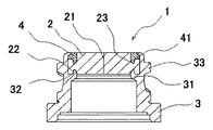
FIG. 1 is a perspective view showing an embodiment of the medical connector of the present invention, and FIG. 2 is a longitudinal sectional view of the medical connector shown in FIG. FIG. 3 is a sectional view showing a state of connection between the medical connector of the present invention and the luer lock connector. FIG. 4 is a cross-sectional view showing a method for joining the medical connector of the present invention, and FIG. 5 is a perspective view showing an example of use of the medical connector of the present invention.
図1および図2に示されるように、本発明の医療用コネクタ1は、中央部にスリット21を有するディスク状の弁部材2と、弁部材2の周縁部を狭持するハウジング3と、弁部材2の中央部分を除く上部の周縁に配置されるリング部材4とを有してなる。前記弁部材2は、ハウジング3の内周面に内方向へ突出するよう設けられた台座31上に戴置され、上部に配置されるリング部材4とハウジング3とが接合されることにより、ハウジング3内に固定される。
本発明の医療用コネクタ1は、輸液ルート上に配置され、シリンジやルアーコネクタ等の医療用接続具の先端部が弁部材2の上方から挿入されることでスリット21が押し開かれ、輸液ルートと接続具との内部連通を可能とするものである
As shown in FIGS. 1 and 2, the
The
本発明の医療用コネクタ1で用いられるディスク状の弁部材2は、直径が5.0〜6.5mm、高さが1.0〜3.0mmの略円柱状の部材である。図3に示されるように、弁部材2の直径が5.0mmより小さいと、外径が約4.0mmに統一されたルアーロックコネクタ5の雄ルアー51の挿入は困難になる。また、弁部材2の直径が6.5mmより大きいと、医療用コネクタ1の外径が大きくなり、ルアーロックコネクタ5の雌ネジ52との接続が困難になる。また、弁部材2の高さが1.0mmよりも小さいと、接続具挿入時の気密性が低下し、高さが3.0mmよりも大きいと、挿入具の挿入抵抗が大きくなり挿入が困難となる。
The disc-
前記弁部材2は、気密性や再封止性を考慮し、イソプレンゴムやシリコーンゴム等の合成ゴム、天然ゴム、熱可塑性エラストマーなどから選択される材料を用いて、プレス成形することにより成形される。さらに、成形された弁部材2は、鋭利な刃を貫通させること等によりスリット21が形成される。このスリット21の形状としては、直線状のものや十字のものがあげられる。
The
さらに、前記弁部材2には、下面に後述するハウジング3の台座31に嵌合しうる溝22や、上面に後述するリング部材4を配置するための環状溝23が設けられていてもよい。これらの溝22および23は、弁部材2とハウジング3またはリング部材4とをより安定に固定するためのものであり、その形状は図示されるものに限定されず、ハウジング3の台座31およびリング部材4の形状に応じて適宜変更することができる。
Further, the
本発明の医療用コネクタ1で用いられるハウジング3は、前記弁部材2を内部に固定できる内径を有する略筒状の部材である。前記ハウジング3は、内部に固定される弁部材2のスリット21が挿入された接続具の抜去後に再度封止しうるよう、弁部材2の周縁部を狭持しうる内径を有していることが好ましく、具体的にはその内径が弁部材2の直径に等しいことが好ましい。また、前記ハウジング3の外径は、ISO594で規定された医療用ルアーロックコネクタの接続が可能であるよう、6.0〜7.0mmであることが好ましい。またルアーロックコネクタ5の雌ネジ52に螺合するネジ部33をハウジング3の外周面に設けた場合、ハウジング3の外径は7.2〜8.0mmであることが好ましい。
The
ハウジング3には、内部に弁部材2を配置するために、内周面に内方向へ突出するように台座31が設けられる。弁部材2がハウジング3内に挿入され台座31上に戴置された時に、両者の固定がさらに安定するよう、台座31上面に上方へ突出する突部32が設けられ、弁部材2の下面には前記突部32に対応する形状の溝部22が設けられることがより好ましい。前記突部32および溝部22の形状については限定されないが、好ましくは前記突部32よび溝部22ともに環状である。
The
また、前記ハウジング3の外周面には、前述したように、ルアーロックコネクタ5と螺合可能なネジ部33が設けられてなることが好ましい。ルアーロックコネクタ5とは、図3に示されるように雄ルアー51の外周に雌ネジ52が設けられた接続具を示している。前記ネジ部33は、好ましくはISO594で規定された、ネジの山頂径が7.0±0.2mmであり、ネジの谷底径が8.0±0.1mmである医療用ルアーロックコネクタ5との接続が可能な二条ネジである。
Further, it is preferable that the outer peripheral surface of the
前記ハウジング3は、弁部材2を確実に保持できる強度を持った材料から形成されることが好ましく、材料としては具体的にはポリプロピレン、ポリエチレン、ポリカーボネート、ポリスチレン、ポリアセタール等の熱可塑性樹脂が好ましく用いられる。ハウジング3は、これらの材料から、射出成形等によって成形される。
The
本発明の医療用コネクタ1で用いられるリング部材4は、前記弁部材2をハウジング3内に固定するために、弁部材2の上部に配置される環状部材である。リング部材4は、ハウジング3の上端部に配置されるが、ハウジング3の上端部とリング部材4の上面との間に段差が形成されず確実に面一となるよう、リング部材4の周縁部がハウジング3に狭持されるよう配置されることがより好ましい。したがって、リング部材4の外径はハウジング3の上端部の内径と等しいことが好ましい。リング部材4の材料としては、ハウジング3の材料と同様、ポリプロピレン、ポリエチレン、ポリカーボネート、ポリスチレン、ポリアセタール等の熱可塑性樹脂が好ましく用いられる。
またリング部材4は、接続具が弁部材2のスリット21に挿入される接続操作を阻害しないよう、弁部材2の中央部分を除く上部の周縁に配置されるため、その内径は4.4mm以上であることが好ましい。内径が4.4mmよりも小さいと、ISO594で規定される医療用ルアーロックコネクタ5を挿入した場合、コネクタ5の雄ルアー51とリング部材4が接触して雄ルアー51を傷つけ、接続時の気密性が低下するおそれがある。
The
Moreover, since the
リング部材4は弁部材2上部に配置されたときに、既に弁部材2の上面とリング部材4の上面とが面一に構成されるよう、弁部材2の上面に設けられた環状溝23に配置されることが好ましい。この場合、弁部材2に設けられる環状溝23の深さおよび形状は、リング部材4の高さおよび下面の形状と合わせて形成される。例えば、図2に示されるように、リング部材4の下面の内周縁に下方へ環状に突出する爪部41を設け、弁部材2の上面の外周縁には前記爪部41に対応する形状の環状溝23を設けることにより、リング部材4と弁部材2とを予め安定に配置させることができる。
In the
次に、本発明の医療用コネクタの製造方法について説明する。本発明の医療用コネクタは、ハウジング3の台座31上に弁部材2を対置し、さらに弁部材2上部の周縁にリング部材4を配置した後、スウェージング加工によってリング部材4とハウジング3の上端部とが接合されることにより製造される。
スウェージング加工によるリング部材4とハウジング3の上端部との接合方法の一例を図4に示される断面図を用いて説明する。図4(a)に示されるリング部材4は、予め上面の外周縁に凹部42が形成されている。ハウジング3内部に配置された弁部材2の上面およびリング部材4の上面は、面一に配置されてはいるが、等しくハウジング3の上端部よりも0〜0.2mm上方(図4(a)参照)か、あるいは0〜1.0mm下方(図示せず)に位置されている。この状態で、両端に曲面62が形成された凹部61を有するホーン6を用いてスウェージング加工を行うと、ハウジング3の上端部が溶融しながら内方向へと変形し、リング部材4の周縁部と接合される。このとき、溶融したハウジングの上端部がリング部材4に形成された凹部42へと流れ込み、図4(b)に示されるように、ハウジング3の上面、リング部材4の上面および弁部材2の上面は全て面一となる。
このようなスウェージング加工に好適な加工条件は、超音波振動を用いる場合は、超音波振動周波数が約20〜40kHz、発振時間が約0.3秒、発振時の荷重が約20〜100Nであるが、超音波振動に代えて高周波誘導加熱などの手段を用いることも可能である。
Next, the manufacturing method of the medical connector of this invention is demonstrated. In the medical connector of the present invention, the
An example of a method of joining the
Processing conditions suitable for such swaging processing are as follows. When ultrasonic vibration is used, the ultrasonic vibration frequency is about 20 to 40 kHz, the oscillation time is about 0.3 seconds, and the load during oscillation is about 20 to 100 N. However, it is also possible to use means such as high frequency induction heating instead of ultrasonic vibration.
図5に本発明の医療用コネクタ1の具体的な使用例を示す。図5(a)に示される使用例は、プラグベース7と接合することによりプラグとしたものであり、図5(b)に示される使用例は、T字管ベース8と接合することによりT字混注管としたものであり、図5(c)に示される使用例は、三方活栓ベース9と接合することにより三方活栓としたものである。
いずれの使用例においても、本発明の医療用コネクタ1に接続される接続具、特にルアーロックコネクタ5は、螺合により医療用コネクタ1に強固に固定されるため、他の部品を用いたり、あるいは使用者が医療用コネクタ1を保持することによって接続状態を保持する必要がない。この効果は、図5(c)に示される三方活栓において特に顕著であり、接続具の接続後に、接続状態を保持することなく三方活栓の操作を行うことができる。
FIG. 5 shows a specific use example of the
In any of the usage examples, the connection tool connected to the
1 医療用コネクタ
2 弁部材
21 スリット
22 溝部
23 環状溝
3 ハウジング
31 台座
32 突部
33 ネジ部
4 カバー部材
41 爪部
5 ルアーロックコネクタ
DESCRIPTION OF
Claims (6)
(a)中央部にスリットを有するディスク状の弁部材、弁部材の周縁部を狭持しうる略筒状のハウジング、および弁部材の中央部分を除く上部の周縁に配置される環状のリング部材を準備する工程
(b)前記ハウジング内周面に内方向へ突出するよう設けられた弁部材を戴置しうる台座上に、前記弁部材を戴置する工程
(c)前記弁部材上部に前記リング部材を配置し、スウェージング加工によってリング部材とハウジングを接合する工程。 A method for producing a medical connector comprising the following steps,
(A) A disk-shaped valve member having a slit in the center, a substantially cylindrical housing that can hold the periphery of the valve member, and an annular ring member disposed on the periphery of the upper portion excluding the center of the valve member (B) placing the valve member on a pedestal on which a valve member provided so as to protrude inwardly on the inner peripheral surface of the housing can be placed (c) A step of arranging the ring member and joining the ring member and the housing by swaging.
(a)中央部にスリットを有するディスク状の弁部材、弁部材の周縁部を狭持しうる略筒状のハウジング、および弁部材の中央部分を除く上部の周縁に配置される環状のリング部材を準備する工程
(b)前記ハウジング内周面に内方向へ突出するよう設けられた弁部材を戴置しうる台座上に、前記弁部材を戴置する工程
(c)前記弁部材の上面に設けられた環状溝に前記リング部材を配置し、弁部材の上面およびリング部材の上面を面一に配置する工程
(d)スウェージング加工によってハウジングの上端部を溶融しながら内方向へと変形し、リング部材の上面の外周縁に形成された凹部へと流し込むことによりリング部材とハウジングを接合し、ハウジングの上面、リング部材の上面および弁部材の上面を全て面一にする工程。 A method for producing a medical connector comprising the following steps,
(A) A disk-shaped valve member having a slit in the center, a substantially cylindrical housing that can hold the periphery of the valve member, and an annular ring member disposed on the periphery of the upper portion excluding the center of the valve member (B) A step of placing the valve member on a pedestal on which a valve member provided to protrude inwardly on the inner peripheral surface of the housing can be placed. (C) On the upper surface of the valve member The ring member is disposed in the annular groove provided, and the upper surface of the valve member and the upper surface of the ring member are flush with each other. (D) The housing is deformed inward while melting the upper end of the housing by swaging. The step of joining the ring member and the housing by pouring into a recess formed on the outer peripheral edge of the upper surface of the ring member, and making the upper surface of the housing, the upper surface of the ring member, and the upper surface of the valve member all flush.
Priority Applications (1)
| Application Number | Priority Date | Filing Date | Title |
|---|---|---|---|
| JP2008144648A JP5290630B2 (en) | 2007-06-05 | 2008-06-02 | Medical connector and manufacturing method thereof |
Applications Claiming Priority (3)
| Application Number | Priority Date | Filing Date | Title |
|---|---|---|---|
| JP2007149133 | 2007-06-05 | ||
| JP2007149133 | 2007-06-05 | ||
| JP2008144648A JP5290630B2 (en) | 2007-06-05 | 2008-06-02 | Medical connector and manufacturing method thereof |
Related Child Applications (1)
| Application Number | Title | Priority Date | Filing Date |
|---|---|---|---|
| JP2013119801A Division JP2013198755A (en) | 2007-06-05 | 2013-06-06 | Medical connector and method of manufacturing the same |
Publications (2)
| Publication Number | Publication Date |
|---|---|
| JP2009011820A JP2009011820A (en) | 2009-01-22 |
| JP5290630B2 true JP5290630B2 (en) | 2013-09-18 |
Family
ID=39720465
Family Applications (5)
| Application Number | Title | Priority Date | Filing Date |
|---|---|---|---|
| JP2008144648A Active JP5290630B2 (en) | 2007-06-05 | 2008-06-02 | Medical connector and manufacturing method thereof |
| JP2013119801A Pending JP2013198755A (en) | 2007-06-05 | 2013-06-06 | Medical connector and method of manufacturing the same |
| JP2014159240A Active JP5817896B2 (en) | 2007-06-05 | 2014-08-05 | Medical connector |
| JP2015211097A Active JP6315288B2 (en) | 2007-06-05 | 2015-10-27 | Medical connector and manufacturing method thereof |
| JP2015211093A Active JP6183668B2 (en) | 2007-06-05 | 2015-10-27 | Medical connector and manufacturing method thereof |
Family Applications After (4)
| Application Number | Title | Priority Date | Filing Date |
|---|---|---|---|
| JP2013119801A Pending JP2013198755A (en) | 2007-06-05 | 2013-06-06 | Medical connector and method of manufacturing the same |
| JP2014159240A Active JP5817896B2 (en) | 2007-06-05 | 2014-08-05 | Medical connector |
| JP2015211097A Active JP6315288B2 (en) | 2007-06-05 | 2015-10-27 | Medical connector and manufacturing method thereof |
| JP2015211093A Active JP6183668B2 (en) | 2007-06-05 | 2015-10-27 | Medical connector and manufacturing method thereof |
Country Status (4)
| Country | Link |
|---|---|
| US (2) | US9044585B2 (en) |
| EP (1) | EP2014332A1 (en) |
| JP (5) | JP5290630B2 (en) |
| CN (1) | CN101318055B (en) |
Families Citing this family (61)
| Publication number | Priority date | Publication date | Assignee | Title |
|---|---|---|---|---|
| US20060161115A1 (en) | 2004-11-05 | 2006-07-20 | Fangrow Thomas F | Soft-grip medical connector |
| ATE506985T1 (en) | 2006-10-25 | 2011-05-15 | Icu Medical Inc | MEDICAL CONNECTOR |
| JP5290630B2 (en) * | 2007-06-05 | 2013-09-18 | ニプロ株式会社 | Medical connector and manufacturing method thereof |
| JP4999604B2 (en) * | 2007-08-23 | 2012-08-15 | 日本コヴィディエン株式会社 | Connector connection structure |
| US9168366B2 (en) | 2008-12-19 | 2015-10-27 | Icu Medical, Inc. | Medical connector with closeable luer connector |
| CN102264433B (en) * | 2008-12-26 | 2013-12-25 | 尼普洛株式会社 | Medical connector |
| US8454579B2 (en) | 2009-03-25 | 2013-06-04 | Icu Medical, Inc. | Medical connector with automatic valves and volume regulator |
| DE202010000078U1 (en) * | 2010-01-22 | 2011-05-26 | Hopf, Hans-Jürgen, 90513 | Fluid-flow connection systems for use in medicine and medical technology |
| DE202009005077U1 (en) * | 2009-07-28 | 2010-12-23 | Fa. Hans Jürgen Hopf | Connection system for fluid connections |
| US8323249B2 (en) | 2009-08-14 | 2012-12-04 | The Regents Of The University Of Michigan | Integrated vascular delivery system |
| USD644731S1 (en) | 2010-03-23 | 2011-09-06 | Icu Medical, Inc. | Medical connector |
| FR2958401A1 (en) * | 2010-04-01 | 2011-10-07 | Braun Medical Sas | DEVICE FOR COLLECTING A LIQUID SAMPLE FROM A FLEXIBLE POCKET |
| US8758306B2 (en) | 2010-05-17 | 2014-06-24 | Icu Medical, Inc. | Medical connectors and methods of use |
| WO2011146772A1 (en) | 2010-05-19 | 2011-11-24 | Tangent Medical Technologies Llc | Safety needle system operable with a medical device |
| US8771230B2 (en) | 2010-05-19 | 2014-07-08 | Tangent Medical Technologies, Llc | Integrated vascular delivery system |
| CN103052423B (en) * | 2010-09-28 | 2015-05-20 | 泰尔茂株式会社 | Connector |
| JP6553357B2 (en) | 2011-09-09 | 2019-07-31 | アイシーユー・メディカル・インコーポレーテッド | Medical connector with fluid-resistant mating interface |
| US10098767B2 (en) * | 2012-04-27 | 2018-10-16 | Medtronic Vascular, Inc. | Reconfigurable stent-graft delivery system and method of use |
| JP6678390B2 (en) * | 2012-09-21 | 2020-04-08 | ニプロ株式会社 | Medical connector and manufacturing method thereof |
| AU2013342123B2 (en) | 2012-11-12 | 2018-08-02 | Icu Medical, Inc. | Medical connector |
| AU2014238008B2 (en) | 2013-03-15 | 2018-11-08 | Icu Medical, Inc. | Medical connector |
| ITMO20130264A1 (en) * | 2013-09-25 | 2015-03-26 | Giuseppe Maffei | CONNECTOR WITHOUT NEEDLE |
| AU2014364218B2 (en) | 2013-12-11 | 2019-06-06 | Icu Medical, Inc. | Check valve |
| CA2937744C (en) | 2014-02-04 | 2022-08-09 | Icu Medical, Inc. | Self-priming systems and methods |
| JP6399317B2 (en) * | 2014-02-21 | 2018-10-03 | ニプロ株式会社 | Medical connector and method for manufacturing medical connector |
| CN104324445B (en) * | 2014-10-30 | 2017-02-01 | 四川省广元市康康医疗器械有限公司 | Medium-pressure medical three-way valve and medium-pressure sealing process of medium-pressure medical three-way valve |
| USD786427S1 (en) | 2014-12-03 | 2017-05-09 | Icu Medical, Inc. | Fluid manifold |
| JP5968987B2 (en) * | 2014-12-03 | 2016-08-10 | ニプロ株式会社 | Medical valve |
| USD793551S1 (en) | 2014-12-03 | 2017-08-01 | Icu Medical, Inc. | Fluid manifold |
| USD761421S1 (en) | 2015-03-25 | 2016-07-12 | Nipro Corporation | Medical connector |
| EP3297697B1 (en) | 2015-05-18 | 2022-05-11 | Smith & Nephew plc | Negative pressure wound therapy apparatus |
| EP3307228A4 (en) * | 2015-06-14 | 2018-12-26 | Dali Medical Devices Ltd. | Systems for interfacing between a syringe, a drug vial, and a needle |
| GB2557143B (en) | 2015-08-13 | 2021-01-06 | Smith & Nephew Inc | Systems and methods for applying reduced pressure therapy |
| JP6834120B2 (en) * | 2015-09-11 | 2021-02-24 | ニプロ株式会社 | Medical connector |
| JP6812354B2 (en) * | 2015-09-24 | 2021-01-13 | テルモ株式会社 | Medical connector |
| CN105771083A (en) * | 2016-02-01 | 2016-07-20 | 河南科技大学第附属医院 | Shear-free extracorporeal circulation pipeline connector |
| JP2017143946A (en) * | 2016-02-16 | 2017-08-24 | ニプロ株式会社 | Needleless port |
| GB201608603D0 (en) * | 2016-05-16 | 2016-06-29 | Medical Device Creations Ltd | Improved fluid line connector device |
| JP6343636B2 (en) * | 2016-07-06 | 2018-06-13 | ニプロ株式会社 | Medical valve |
| IT201600075597A1 (en) * | 2016-07-19 | 2018-01-19 | Borla Ind | FLOW COMPONENT PARTICULARLY FOR MEDICAL LINES FOR HEMODIALYSIS |
| CN114504307B (en) * | 2016-08-31 | 2024-05-31 | 尼普洛株式会社 | Guide wire connector |
| WO2018066748A1 (en) * | 2016-10-05 | 2018-04-12 | 이현우 | Medical drain unit having luer-lock connection structure |
| KR101892153B1 (en) * | 2016-10-05 | 2018-08-28 | 이현우 | Medical drain unit of with luer-lock connection structure |
| WO2018150267A2 (en) | 2017-02-15 | 2018-08-23 | Smith & Nephew Pte. Limited | Negative pressure wound therapy apparatuses and methods for using the same |
| CA3063662A1 (en) | 2017-05-23 | 2019-11-14 | Sumitomo Bakelite Co., Ltd. | Coronary artery bypass surgery treatment tool, treatment tool, part, medical connector, and medical device |
| US11389582B2 (en) | 2017-09-29 | 2022-07-19 | T.J. Smith And Nephew, Limited | Negative pressure wound therapy apparatus with removable panels |
| EP3689412B1 (en) | 2017-12-26 | 2024-03-27 | Terumo Kabushiki Kaisha | Medical connector |
| GB201813282D0 (en) | 2018-08-15 | 2018-09-26 | Smith & Nephew | System for medical device activation and opertion |
| GB201804347D0 (en) | 2018-03-19 | 2018-05-02 | Smith & Nephew Inc | Securing control of settings of negative pressure wound therapy apparatuses and methods for using the same |
| EP3787704A1 (en) | 2018-04-30 | 2021-03-10 | Smith & Nephew Asia Pacific Pte Limited | Systems and methods for controlling dual mode negative pressure wound therapy apparatus |
| GB201806988D0 (en) | 2018-04-30 | 2018-06-13 | Quintanar Felix Clarence | Power source charging for negative pressure wound therapy apparatus |
| JP6718153B2 (en) * | 2018-05-18 | 2020-07-08 | ニプロ株式会社 | Medical valve |
| GB201808438D0 (en) | 2018-05-23 | 2018-07-11 | Smith & Nephew | Systems and methods for determining blockages in a negative pressure wound therapy system |
| JP7439765B2 (en) | 2018-11-20 | 2024-02-28 | ニプロ株式会社 | male connector |
| CN109432589B (en) * | 2018-12-26 | 2022-03-08 | 台州市路桥瑞豪科技有限公司 | Manufacturing process of needleless dosing connector |
| JP7286495B2 (en) * | 2019-09-19 | 2023-06-05 | テルモ株式会社 | medical connector |
| EP3957352B1 (en) * | 2020-08-18 | 2023-06-07 | Single Use Support GmbH | Sterile connector |
| KR102542907B1 (en) * | 2020-09-09 | 2023-06-15 | 대한약품공업 주식회사 | Integrated Injection Set |
| EP4249037A4 (en) | 2020-11-17 | 2024-09-25 | Nipro Corp | Medical connector |
| KR20220118776A (en) | 2021-02-19 | 2022-08-26 | 이현우 | Connection structure of Medical solution drain set |
| EP4082600A1 (en) * | 2021-04-30 | 2022-11-02 | B. Braun Melsungen AG | Valve, method of manufacturing a valve, cap for a fluid container comprising such valve, fluid container containing such cap, and method for manufacturing such cap |
Family Cites Families (34)
| Publication number | Priority date | Publication date | Assignee | Title |
|---|---|---|---|---|
| US3751049A (en) * | 1971-02-25 | 1973-08-07 | Subterranean Tools Inc | Seal ring and method of making |
| US4219912A (en) | 1978-10-10 | 1980-09-02 | Baxter Travenol Laboratories, Inc. | Injection site having thermoplastically sealed injection port |
| AU607703B2 (en) * | 1986-12-11 | 1991-03-14 | Terumo Kabushiki Kaisha | Blood sampling tube |
| US5178607A (en) * | 1987-07-31 | 1993-01-12 | Lynn Lawrence A | Blood aspiration assembly septum and blunt needle aspirator |
| DE68926627T2 (en) | 1988-01-25 | 1997-01-02 | Baxter Int | Injection site |
| JP2582134B2 (en) | 1988-03-03 | 1997-02-19 | 株式会社 大協精工 | Plug for pharmaceutical plastic container and method for producing the same |
| MX172729B (en) | 1989-11-09 | 1994-01-10 | Baxter Int | DEVICE FOR CANNULA INSERTION |
| JPH063601Y2 (en) | 1991-06-21 | 1994-02-02 | 川澄化学工業株式会社 | Mouth of medical container |
| NZ328241A (en) | 1991-12-18 | 2000-04-28 | Icu Medical Inc | Body element for medical valve including seal in form of tube with closed end presenting swabbable surface |
| US5279571A (en) * | 1991-12-30 | 1994-01-18 | Abbott Laboratories | Access site for fluid delivery system |
| US5515705A (en) * | 1992-01-23 | 1996-05-14 | Board Of Regents, The University Of Texas System | Apparatus and method for deforming a workpiece |
| US5351383A (en) | 1992-07-29 | 1994-10-04 | Minnesota Mining And Manufacturing Company | Method of making an injection or sampling site |
| US7033339B1 (en) * | 1998-05-29 | 2006-04-25 | Becton Dickinson And Company (Part Interest) | Self sealing luer receiving stopcock |
| US5535771A (en) | 1994-08-10 | 1996-07-16 | Becton, Dickinson And Company | Valved PRN adapter for infusion devices |
| US5839715A (en) | 1995-05-16 | 1998-11-24 | Alaris Medical Systems, Inc. | Medical adapter having needleless valve and sharpened cannula |
| US5591137A (en) * | 1995-07-14 | 1997-01-07 | Merit Medical Systems, Inc. | Hemostasis valve with locking seal |
| US6371319B2 (en) * | 1997-09-22 | 2002-04-16 | Abbott Laboratories | Closure system for containers |
| JP3389983B2 (en) | 1997-10-23 | 2003-03-24 | 株式会社ジェイ・エム・エス | Medical injection port |
| DE19938131B4 (en) * | 1999-08-16 | 2006-08-31 | Ti Automotive Technology Center Gmbh | Fuel tank |
| JP3404738B2 (en) * | 2000-09-26 | 2003-05-12 | 株式会社ジェイ・エム・エス | Medical injection port |
| JP2003290362A (en) | 2002-04-02 | 2003-10-14 | Koji Karasawa | Side injection tube |
| US8377039B2 (en) * | 2002-10-04 | 2013-02-19 | Nxstage Medical, Inc. | Injection site for male luer or other tubular connector |
| US7118560B2 (en) * | 2003-02-28 | 2006-10-10 | Creative Plastic Technology, Llc | Needleless Luer activated medical connector |
| JP4289046B2 (en) | 2003-07-04 | 2009-07-01 | 株式会社ジェイ・エム・エス | Medical syringe |
| CA2534390C (en) | 2003-07-09 | 2010-10-05 | Jms Co., Ltd. | Mixture injection port |
| JP2006102255A (en) * | 2004-10-06 | 2006-04-20 | Nippon Sherwood Medical Industries Ltd | Connecting structure of infusion line and connector with the connecting structure |
| JP4292145B2 (en) * | 2004-11-19 | 2009-07-08 | 株式会社ジェイ・エム・エス | Lock connector device for channel communication |
| JP4647365B2 (en) * | 2005-03-31 | 2011-03-09 | 日本シャーウッド株式会社 | Medical connection device |
| JP2007117210A (en) * | 2005-10-25 | 2007-05-17 | Asahi Kinzoku Seisakusho:Kk | Mixed injection tube and valve device |
| US8377010B2 (en) | 2005-11-17 | 2013-02-19 | Becton, Dickinson And Company | Medical access device |
| WO2007120620A2 (en) * | 2006-04-11 | 2007-10-25 | Nypro Inc. | Medical valve with moving member and method |
| JP4802914B2 (en) * | 2006-07-28 | 2011-10-26 | 株式会社ジェイ・エム・エス | Medical pipe joint and line used for transporting infusion or blood using the same |
| JP4848881B2 (en) * | 2006-07-28 | 2011-12-28 | 株式会社ジェイ・エム・エス | Medical pipe joint and line used for transporting infusion or blood using the same |
| JP5290630B2 (en) | 2007-06-05 | 2013-09-18 | ニプロ株式会社 | Medical connector and manufacturing method thereof |
-
2008
- 2008-06-02 JP JP2008144648A patent/JP5290630B2/en active Active
- 2008-06-03 CN CN2008100859151A patent/CN101318055B/en active Active
- 2008-06-04 US US12/155,431 patent/US9044585B2/en not_active Expired - Fee Related
- 2008-06-05 EP EP08010265A patent/EP2014332A1/en not_active Withdrawn
-
2013
- 2013-06-06 JP JP2013119801A patent/JP2013198755A/en active Pending
-
2014
- 2014-02-06 US US14/174,427 patent/US9586036B2/en active Active
- 2014-08-05 JP JP2014159240A patent/JP5817896B2/en active Active
-
2015
- 2015-10-27 JP JP2015211097A patent/JP6315288B2/en active Active
- 2015-10-27 JP JP2015211093A patent/JP6183668B2/en active Active
Also Published As
| Publication number | Publication date |
|---|---|
| JP2014205073A (en) | 2014-10-30 |
| JP2016013486A (en) | 2016-01-28 |
| JP2013198755A (en) | 2013-10-03 |
| CN101318055B (en) | 2012-05-30 |
| JP5817896B2 (en) | 2015-11-18 |
| US9044585B2 (en) | 2015-06-02 |
| JP6183668B2 (en) | 2017-08-23 |
| US9586036B2 (en) | 2017-03-07 |
| EP2014332A1 (en) | 2009-01-14 |
| CN101318055A (en) | 2008-12-10 |
| JP2009011820A (en) | 2009-01-22 |
| US20080306469A1 (en) | 2008-12-11 |
| US20140155837A1 (en) | 2014-06-05 |
| JP2016028753A (en) | 2016-03-03 |
| JP6315288B2 (en) | 2018-04-25 |
Similar Documents
| Publication | Publication Date | Title |
|---|---|---|
| JP5290630B2 (en) | Medical connector and manufacturing method thereof | |
| JP5489081B2 (en) | Medical connector | |
| JP6063036B2 (en) | Connector and infusion set | |
| EP3130366B1 (en) | Medical valve | |
| JP6474035B2 (en) | Medical valve | |
| JP5372490B2 (en) | Medical valve | |
| JP6678390B2 (en) | Medical connector and manufacturing method thereof | |
| EP2623147A1 (en) | Medical instrument with attached needle | |
| JP5660347B2 (en) | Medical valve | |
| JP2015066205A (en) | Medical connector, mixed injection tube, three-way stopcock, and medicament bag | |
| CN106132471B (en) | Connector and infusion assembly | |
| JP6260867B2 (en) | Medical valve | |
| JP6399317B2 (en) | Medical connector and method for manufacturing medical connector | |
| JP5661885B2 (en) | Medical valve | |
| JP6343636B2 (en) | Medical valve | |
| JP6549347B2 (en) | Medical valve | |
| JP6718153B2 (en) | Medical valve | |
| WO2022107796A1 (en) | Medical connector | |
| WO2014162348A1 (en) | Connector, connector connection body, and male connector attachment method | |
| JP2017143946A (en) | Needleless port | |
| JP2018191777A (en) | Connector with cap |
Legal Events
| Date | Code | Title | Description |
|---|---|---|---|
| A621 | Written request for application examination |
Free format text: JAPANESE INTERMEDIATE CODE: A621 Effective date: 20110120 |
|
| A977 | Report on retrieval |
Free format text: JAPANESE INTERMEDIATE CODE: A971007 Effective date: 20120731 |
|
| A131 | Notification of reasons for refusal |
Free format text: JAPANESE INTERMEDIATE CODE: A131 Effective date: 20120911 |
|
| TRDD | Decision of grant or rejection written | ||
| A01 | Written decision to grant a patent or to grant a registration (utility model) |
Free format text: JAPANESE INTERMEDIATE CODE: A01 Effective date: 20130507 |
|
| A61 | First payment of annual fees (during grant procedure) |
Free format text: JAPANESE INTERMEDIATE CODE: A61 Effective date: 20130606 |
|
| R150 | Certificate of patent or registration of utility model |
Ref document number: 5290630 Country of ref document: JP Free format text: JAPANESE INTERMEDIATE CODE: R150 |
|
| R250 | Receipt of annual fees |
Free format text: JAPANESE INTERMEDIATE CODE: R250 |
|
| R250 | Receipt of annual fees |
Free format text: JAPANESE INTERMEDIATE CODE: R250 |
|
| R250 | Receipt of annual fees |
Free format text: JAPANESE INTERMEDIATE CODE: R250 |