EP2014332A1 - Medical connector - Google Patents
Medical connector Download PDFInfo
- Publication number
- EP2014332A1 EP2014332A1 EP08010265A EP08010265A EP2014332A1 EP 2014332 A1 EP2014332 A1 EP 2014332A1 EP 08010265 A EP08010265 A EP 08010265A EP 08010265 A EP08010265 A EP 08010265A EP 2014332 A1 EP2014332 A1 EP 2014332A1
- Authority
- EP
- European Patent Office
- Prior art keywords
- housing
- valve member
- ring member
- pedestal
- circumferential edge
- Prior art date
- Legal status (The legal status is an assumption and is not a legal conclusion. Google has not performed a legal analysis and makes no representation as to the accuracy of the status listed.)
- Withdrawn
Links
Images

Classifications
-
- A—HUMAN NECESSITIES
- A61—MEDICAL OR VETERINARY SCIENCE; HYGIENE
- A61M—DEVICES FOR INTRODUCING MEDIA INTO, OR ONTO, THE BODY; DEVICES FOR TRANSDUCING BODY MEDIA OR FOR TAKING MEDIA FROM THE BODY; DEVICES FOR PRODUCING OR ENDING SLEEP OR STUPOR
- A61M39/00—Tubes, tube connectors, tube couplings, valves, access sites or the like, specially adapted for medical use
- A61M39/22—Valves or arrangement of valves
-
- A—HUMAN NECESSITIES
- A61—MEDICAL OR VETERINARY SCIENCE; HYGIENE
- A61M—DEVICES FOR INTRODUCING MEDIA INTO, OR ONTO, THE BODY; DEVICES FOR TRANSDUCING BODY MEDIA OR FOR TAKING MEDIA FROM THE BODY; DEVICES FOR PRODUCING OR ENDING SLEEP OR STUPOR
- A61M39/00—Tubes, tube connectors, tube couplings, valves, access sites or the like, specially adapted for medical use
- A61M39/02—Access sites
- A61M39/04—Access sites having pierceable self-sealing members
- A61M39/045—Access sites having pierceable self-sealing members pre-slit to be pierced by blunt instrument
-
- A—HUMAN NECESSITIES
- A61—MEDICAL OR VETERINARY SCIENCE; HYGIENE
- A61M—DEVICES FOR INTRODUCING MEDIA INTO, OR ONTO, THE BODY; DEVICES FOR TRANSDUCING BODY MEDIA OR FOR TAKING MEDIA FROM THE BODY; DEVICES FOR PRODUCING OR ENDING SLEEP OR STUPOR
- A61M39/00—Tubes, tube connectors, tube couplings, valves, access sites or the like, specially adapted for medical use
- A61M39/10—Tube connectors; Tube couplings
-
- A—HUMAN NECESSITIES
- A61—MEDICAL OR VETERINARY SCIENCE; HYGIENE
- A61M—DEVICES FOR INTRODUCING MEDIA INTO, OR ONTO, THE BODY; DEVICES FOR TRANSDUCING BODY MEDIA OR FOR TAKING MEDIA FROM THE BODY; DEVICES FOR PRODUCING OR ENDING SLEEP OR STUPOR
- A61M39/00—Tubes, tube connectors, tube couplings, valves, access sites or the like, specially adapted for medical use
- A61M39/22—Valves or arrangement of valves
- A61M39/26—Valves closing automatically on disconnecting the line and opening on reconnection thereof
-
- A—HUMAN NECESSITIES
- A61—MEDICAL OR VETERINARY SCIENCE; HYGIENE
- A61M—DEVICES FOR INTRODUCING MEDIA INTO, OR ONTO, THE BODY; DEVICES FOR TRANSDUCING BODY MEDIA OR FOR TAKING MEDIA FROM THE BODY; DEVICES FOR PRODUCING OR ENDING SLEEP OR STUPOR
- A61M39/00—Tubes, tube connectors, tube couplings, valves, access sites or the like, specially adapted for medical use
- A61M39/10—Tube connectors; Tube couplings
- A61M2039/1033—Swivel nut connectors, e.g. threaded connectors, bayonet-connectors
-
- A—HUMAN NECESSITIES
- A61—MEDICAL OR VETERINARY SCIENCE; HYGIENE
- A61M—DEVICES FOR INTRODUCING MEDIA INTO, OR ONTO, THE BODY; DEVICES FOR TRANSDUCING BODY MEDIA OR FOR TAKING MEDIA FROM THE BODY; DEVICES FOR PRODUCING OR ENDING SLEEP OR STUPOR
- A61M39/00—Tubes, tube connectors, tube couplings, valves, access sites or the like, specially adapted for medical use
- A61M39/10—Tube connectors; Tube couplings
- A61M2039/1072—Tube connectors; Tube couplings with a septum present in the connector
-
- A—HUMAN NECESSITIES
- A61—MEDICAL OR VETERINARY SCIENCE; HYGIENE
- A61M—DEVICES FOR INTRODUCING MEDIA INTO, OR ONTO, THE BODY; DEVICES FOR TRANSDUCING BODY MEDIA OR FOR TAKING MEDIA FROM THE BODY; DEVICES FOR PRODUCING OR ENDING SLEEP OR STUPOR
- A61M39/00—Tubes, tube connectors, tube couplings, valves, access sites or the like, specially adapted for medical use
- A61M39/10—Tube connectors; Tube couplings
- A61M2039/1083—Tube connectors; Tube couplings having a plurality of female connectors, e.g. Luer connectors
-
- A—HUMAN NECESSITIES
- A61—MEDICAL OR VETERINARY SCIENCE; HYGIENE
- A61M—DEVICES FOR INTRODUCING MEDIA INTO, OR ONTO, THE BODY; DEVICES FOR TRANSDUCING BODY MEDIA OR FOR TAKING MEDIA FROM THE BODY; DEVICES FOR PRODUCING OR ENDING SLEEP OR STUPOR
- A61M39/00—Tubes, tube connectors, tube couplings, valves, access sites or the like, specially adapted for medical use
- A61M39/10—Tube connectors; Tube couplings
- A61M2039/1088—Tube connectors; Tube couplings having a plurality of male connectors, e.g. Luer connectors
-
- Y—GENERAL TAGGING OF NEW TECHNOLOGICAL DEVELOPMENTS; GENERAL TAGGING OF CROSS-SECTIONAL TECHNOLOGIES SPANNING OVER SEVERAL SECTIONS OF THE IPC; TECHNICAL SUBJECTS COVERED BY FORMER USPC CROSS-REFERENCE ART COLLECTIONS [XRACs] AND DIGESTS
- Y10—TECHNICAL SUBJECTS COVERED BY FORMER USPC
- Y10T—TECHNICAL SUBJECTS COVERED BY FORMER US CLASSIFICATION
- Y10T29/00—Metal working
- Y10T29/49—Method of mechanical manufacture
- Y10T29/49826—Assembling or joining
Definitions
- the present invention relates to a medical connector capable of allowing a connection tool with a luer lock connector to be connected thereto upon mixing/injecting medicinal solution into an infusion route, or path, or drawing out body fluid therethrough.
- a medical connector to which a medical connection tool such as a syringe or a luer lock connector can be connected, is disposed in an infusion route in order to mix and inject medicinal solution into the infusion route or to draw out body fluid therethrough.
- a cylindrical connector called a mechanical valve type in which a bellows cylindrical rubber valve with a spike built in the center portion thereof (see, for example, Japanese Patent Laid-Open No. 7-505064 or Japanese Patent Laid-Open No. 10-323397 ) and a connector called a split septum type which comprises a housing provided with a disc shaped valve (see, for example, Japanese Patent Laid-Open No. 11-197254 ).
- the mechanical valve-type connector is configured to internally communicate the connection tool with the infusion route in such a manner that a male luer of a connection tool is inserted into an opening of the connector while pushing a rubber valve and then, a slit of the distal end portion of the rubber valve is opened by the spike at the center portion.
- the mechanical valve-type connector is formed into a cylindrical shape so as to be connected to the luer lock connector, manufacturing cost increases because the shape of the rubber valve is complicated.
- the split septum-type connector is a connector formed by a housing to which the disc shaped valve is fixed, and manufacturing cost decreases because the shape is simple.
- the split septum-type connector is configured to allow the infusion route to communicate with the connection tool in such a manner that the male luer of the connection tool is directly inserted into the slit of the disc shaped valve to open the slit. Accordingly, in order to maintain resealing performance of the slit, the disc shaped valve is fixed to the inside of the housing so that an elastic repulsive force is large.
- a connector disclosed in Japanese Patent Laid-Open No. 11-197254 is configured such that a housing of which the upper end portion is deformed inward is disposed so as to cover the valve from the upside and then a holder member is used to fix the housing.
- a stepped portion is not formed on the upper surface of the connector, the shape becomes complicated because the number of components increases.
- the outer diameter of the connector itself becomes large, it is not possible to carry out a connection operation of the luer lock connector in which a female screw is formed on the outer circumference of the male luer. Accordingly, when the connection operation of the luer lock connector is carried out, it is necessary to use an exclusive connector, thereby deteriorating the merit that the shape of the split septum-type connector is simple.
- An object of the invention is therefore to provide a medical connector capable of allowing a luer lock connector to be connected thereto without using an exclusive connector, in which the shape or the assembling operation is not complicated and a stepped portion is not formed between the upper surfaces of the valve and the housing.
- the inventors have carefully studied the above-described problems and then found out that the assembling operation can be easily carried out without a stepped portion formed between the upper surfaces of the valve member and the housing in such a manner that the upper end portion of the housing is not directly subjected to the swaging process, but the annular ring member disposed on the upper surface of the disc shaped valve member and the upper end portion of the housing are subjected to the swaging process. Accordingly, the inventors have found out that the connection operation of the luer lock connector can be carried out without using an exclusive connector or complicating the shape thereof because the valve member is firmly fixed to the housing, thereby developing the invention.
- a medical connector including: a disc shaped valve member which has a slit formed at a center portion thereof; a housing with a substantially cylindrical shape which sandwiches a circumferential edge portion of the valve member; and an annular ring member which is disposed on an upper circumferential edge of the valve member other than the center portion thereof, wherein the housing has a pedestal which is formed in an inner circumferential surface thereof so as to protrude inward, the valve member being placed on the pedestal, and wherein the valve member is fixed to the inside of the housing by allowing the ring member and the housing to be joined to each other by a swaging process after the valve member is placed on the pedestal in the housing.
- an annular groove may be formed in an upper surface of the valve member and the ring member may be disposed in the annular groove of the valve member, so that the upper surface of the valve member is flush with an upper surface of the ring member.
- a concave portion is formed in an outer circumferential edge of the upper surface of the ring member in advance and an upper end portion of the housing which is melted by the swaging process flows into the concave portion, so that the upper surfaces of the housing, the ring member, and the valve member are flush with one another.
- a screw portion is formed in an outer circumferential surface of the housing so as to be screw-connected to a luer lock connector.
- a method for producing the medical connector comprising; preparing a disc shaped valve member which has a slit formed at a center portion thereof, a housing with a substantially cylindrical shape which sandwiches a circumferential edge portion of the valve member; and an annular ring member which is disposed on an upper circumferential edge of the valve member other than the center portion thereof, wherein the housing has a pedestal which is formed in an inner circumferential surface of the housing so as to protrude inward, placing the valve member on the pedestal, and joining the annular ring member to an upper portion of the housing by a swaging process so as to fix the valve member in the housing.
- the ring member is joined to the upper end portion of the housing by the swaging process in a state that the annular ring member is disposed on the upper surface of the valve member, it is possible to firmly fix the valve member to the inside of the housing without complicating the shape or the assembling operation.
- the ring member is disposed on the upper surface of the valve member so that the upper surface of the valve member is flush with the upper surface of the ring member, it is possible to more surely prevent a stepped portion from being formed between the upper surfaces of the valve member and the ring member during the swaging process, and thus germs cannot be mixed with the fluid in the infusion route.
- the medical connector of the invention with such a configuration, since the outer diameter of the connector itself does not increase, the medical connector can be directly connected to the luer lock connector, and thus it is not necessary to use the exclusive connector.
- FIG. 1 is a perspective view illustrating a medical connector according to an embodiment of the invention.
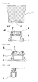
- FIG. 2 is a longitudinal sectional view illustrating the medical connector shown in FIG. 1.
- FIG. 3 is a sectional view illustrating a state where a luer lock connector is connected to the medical connector according to the invention.
- FIGS. 4A and 4B are explanatory views illustrating a method of forming the medical connector according to the invention.
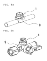
- FIGS. 5A , 5B, and 5C are perspective views illustrating usage examples of the medical connector according to the invention.
- a medical connector 1 includes a disc shaped valve member 2 having a slit 21 formed at the center thereof, a housing 3 which sandwiches a circumferential edge of the valve member 2, and a ring member 4 which is disposed in the upper circumferential edge other than the center portion of the valve member 2.
- the valve member 2 is placed on a pedestal 31 which is formed in the inner circumferential surface of the housing 3 so as to protrude inward, and is fixed to the housing 3 by allowing the housing 3 and the ring member 4 disposed in the upper portion to be joined to each other.
- the medical connector 1 is disposed in an infusion route and allows the infusion route to internally communicate with the inside of a connection tool in such a manner that a distal end portion of a medical connection tool such as a syringe or a luer connector is inserted into the valve member 2 from the upside to thereby open the slit 21.
- a medical connection tool such as a syringe or a luer connector
- the disc shaped valve member 2 which is used in the medical connector 1 according to the invention is formed into a substantially cylindrical member with a diameter in the range of 5.0 to 6.5 mm and a height in the range of 1.0 to 3.0 mm.
- a diameter in the range of 5.0 to 6.5 mm As shown in FIG. 3 , when the diameter of the valve member 2 is smaller than 5.0 mm, it is difficult to insert a male luer 51 of a luer lock connector 5 having a standardized outer diameter of about 4.0 mm into the connector 1.
- the diameter of the valve member 2 is larger than 6.5 mm, an outer diameter of the medical connector 1 becomes large, and thus it is difficult to connect a female screw 52 of the luer lock connector 5 to the medical connector 1.
- the valve member 2 is formed by a press moldings using a material that is selected from synthetic rubber such as isoprene rubber, natural rubber, silicone, thermoplastic elastomer, and the like in consideration of air-tightness or resealing.
- a slit 21 is formed in the valve member 2 by allowing a sharp knife to pass therethrough.
- the slit 21 may be formed into a linear shape or a cross shape.
- valve member 2 may be provided with a groove 22 formed on a lower surface thereof so as to be fitted to the pedestal 31 of the housing 3 and an annular groove 23 formed on an upper surface thereof so as to dispose the ring member 4 described below thereon.
- the grooves 22 and 23 are configured to more stably fix the housing 3 or the ring member 4 to the valve member 2, and the shape thereof is not limited to that shown in the drawings, but may be appropriately modified in accordance with the shape of the ring member 4 and the pedestal 31 of the housing 3.
- the housing 3 used for the medical connector 1 according to the invention is formed into a substantially cylindrical member with an inner diameter allowing the valve member 2 to be fixed to the inside thereof. It is desirable that the housing 3 has an inner diameter allowing the circumferential edge of the valve member 2 to be sandwiched in order to reseal the slit 21 of the valve member 2 fixed to the inside of the housing 3 after drawing out the connection tool inserted into the slit 21. Specifically, it is desirable that the inner diameter of the housing 3 is identical with the diameter of the valve member 2. In addition, it is desirable that the outer diameter of the housing 3 is in the range of 6.0 to 7.0 mm so that a medical luer lock connector based on ISO 594 standard can be connected thereto. When a screw portion 33 which is screw-connected to the female screw 52 of the luer lock connector 5 is formed in the outer circumferential surface of the housing 3, it is desirable that the outer diameter of the housing 3 is in the range of 7.2 to 8.0 mm.
- the pedestal 31 is formed in the inner circumferential surface of the housing 3 so as to protrude inward.
- a protrusion 32 is formed in the upper surface of the pedestal 31 so as to protrude upward and the groove 22 is formed in the lower surface of the valve member 2 so as to correspond to the protrusion 32.
- the shapes of the protrusion 32 and the groove 22 are not limited, but it is desirable that the protrusion 32 and the groove 22 are formed into a ring shape.
- a screw portion 33 is formed in the outer circumferential surface of the housing 3 so as to be screw-connected to the luer lock connector 5.
- the luer lock connector 5 indicates the connection tool in which the female screw 52 is formed in the outer circumference of the male luer 51.
- the screw portion 33 is preferably a double-thread screw to which the medical luer lock connector 5 based on ISO 594 standard having a crest diameter (diameter of the thread) of 7. 0 ⁇ 0.2 mm and a root diameter (diameter of the screw between the threads) of 8.0 ⁇ 0.1 mm can be connected.
- the housing 3 is formed of material having strength for surely holding the valve member 2, and thermoplastic resin such as polypropylene, polyethylene, polycarbonate, polystyrene, or polyacetal can be preferably used as the material.
- the housing 3 is formed of these materials by injection molding or the like.
- the ring member 4 used for the medical connector 1 according to the invention is an annular member which is disposed on the upper portion of the valve member 2 so as to fix the valve member 2 to the inside of the housing 3.
- the ring member 4 is disposed at the upper end portion of the housing 3, it is more desirable that the circumferential edge portion of the ring member 4 is sandwiched by the housing 3 in order to surely allow the upper end portion of the housing 3 to be flush with the upper surface of the ring member 4 without a stepped portion.
- the outer diameter of the ring member 4 is identical with the inner diameter of the upper end portion of the housing 3 and is identical or substantially the same as the outer diameter of the valve member 2.
- the ring member 4 is preferably formed of the same material as that of the housing, that is, a thermoplastic resin such as polypropylene, polyethylene, polycarbonate, polystyrene, or polyacetal.
- the ring member 4 is disposed on the upper circumferential edge portion of the valve member 2 other than the center portion thereof in order not to interrupt a connection operation in which the connection tool is inserted into the slit 21, it is desirable that the inner diameter is not less than 4.4 mm.
- the inner diameter is smaller than 4.4 mm and then the medical luer lock connector 5 based on ISO 594 standard is inserted, there arises a problem that the male luer 51 of the luer lock connector 5 contacts with the ring member 4 to thereby damage the male luer 51, so that air-tightness during a connection deteriorates.
- the ring member 4 is disposed on the upper portion of the valve member 2, it is preferable that the ring member 4 is disposed in an annular groove 23 which is formed in the upper surface of the valve member 2 so that the upper surface of the valve member 2 is flush with the upper surface of the ring member 4.
- the shape and the depth of the annular groove 23 which is formed in the valve member 2 correspond to the height and the shape of the lower surface of the ring member 4.
- a claw portion 41 with a ring shape is formed in the inner circumferential edge portion of the lower surface of the ring member 4 so as to protrude downward.
- an annular groove 23 is formed in the outer circumferential edge portion of the upper surface of the valve member 2 so as to correspond to the claw portion 41 . Accordingly, it is possible to stably dispose the ring member 4 in the valve member 2.
- the ring member 4 which is disposed on the upper circumferential edge portion of the valve member 2 is joined to the upper end portion of the housing 3 by a swaging process.
- An exemplary joint method will be described with reference to the sectional views shown in FIGS. 4A and 4B .
- a concave portion 42 is formed in the outer circumferential edge of the upper surface of the ring member 4 as shown in FIG. 4A .
- the upper surface of the ring member 4 is flush with the upper surface of the valve member 2 which is disposed in the housing 3, both of the upper surface of the ring member 4 and the upper surface of the valve member 2 are disposed at a position in 0 to 0.2 millimeter above the upper end portion of the housing 3 (shown in FIG.
- a frequency of an ultrasonic vibration is about in the range of 20 to 40 kHz
- an oscillation time is about 0.3 sec
- a load during the oscillation is about in the range of 20 to 100 N in a case that an ultrasonic vibration is used, but other means such as high-frequency induction heating may be used instead of the ultrasonic vibration.
- One of the specific methods for producing a medical connector 1 comprises; preparing a disc shaped valve member 2 which has a slit formed at a center portion thereof; a housing 3 with a substantially cylindrical shape which sandwiches a circumferential edge portion of the valve member 2; and an annular ring member 4 which is disposed on an upper circumferential edge of the valve member 2 other than at the center portion thereof, wherein an annular groove 23 is formed in an upper surface of the valve member 2, wherein the housing 3 has a pedestal 31 which is formed in an inner circumferential surface of the housing 3 so as to protrude inward, and wherein a concave portion 42 is formed in an outer circumferential edge of the upper surface of the ring member 4, placing the valve member 2 on the pedestal 31 of the housing 3, disposing the annular ring member 4 in the annular groove 23 of the valve member 2, so that the upper surface of the valve member 2 is flush with an upper surface of the ring member 4, and the surfaces thereof are disposed at a position above an upper end portion of the housing 3, and melting the
- FIGS. 5A , 5B, and 5C are views illustrating specific usage examples of the medical connector 1 according to the invention.
- the usage example shown in FIG. 5A indicates a plug which is connected to a plug base 7.
- the usage example shown in FIG. 5B indicates a T-shaped mixing/injection tube which is connected to a T-shaped tube base 8.
- the usage example shown in FIG. 5C indicates a three-way stopcock which is connected to a three-way stopcock base 9.
- connection tool which is connected to the medical connector 1 according to the invention that is, the luer lock connector 5 is firmly fixed to the medical connector 1 by a screw-connection operation, it is not necessary to maintain the connection state by using other components. Alternatively, it is not necessary for a user to maintain the medical connector 1 so as to maintain the connection state. As a result, this advantage is particularly apparent in the three-way stopcock shown in FIG. 5C , and thus it is possible to operate the three-way stopcock without maintaining the connection state after the connection of the connection tool.
Landscapes
- Health & Medical Sciences (AREA)
- Heart & Thoracic Surgery (AREA)
- Pulmonology (AREA)
- Engineering & Computer Science (AREA)
- Anesthesiology (AREA)
- Biomedical Technology (AREA)
- Hematology (AREA)
- Life Sciences & Earth Sciences (AREA)
- Animal Behavior & Ethology (AREA)
- General Health & Medical Sciences (AREA)
- Public Health (AREA)
- Veterinary Medicine (AREA)
- Infusion, Injection, And Reservoir Apparatuses (AREA)
Abstract
Description
- The present invention relates to a medical connector capable of allowing a connection tool with a luer lock connector to be connected thereto upon mixing/injecting medicinal solution into an infusion route, or path, or drawing out body fluid therethrough.
- In general, a medical connector, to which a medical connection tool such as a syringe or a luer lock connector can be connected, is disposed in an infusion route in order to mix and inject medicinal solution into the infusion route or to draw out body fluid therethrough. As the medical connector, there are known a cylindrical connector called a mechanical valve type in which a bellows cylindrical rubber valve with a spike built in the center portion thereof (see, for example, Japanese Patent Laid-Open No.
7-505064 10-323397 11-197254 - The mechanical valve-type connector is configured to internally communicate the connection tool with the infusion route in such a manner that a male luer of a connection tool is inserted into an opening of the connector while pushing a rubber valve and then, a slit of the distal end portion of the rubber valve is opened by the spike at the center portion. Although the mechanical valve-type connector is formed into a cylindrical shape so as to be connected to the luer lock connector, manufacturing cost increases because the shape of the rubber valve is complicated.
- Meanwhile, the split septum-type connector is a connector formed by a housing to which the disc shaped valve is fixed, and manufacturing cost decreases because the shape is simple. The split septum-type connector is configured to allow the infusion route to communicate with the connection tool in such a manner that the male luer of the connection tool is directly inserted into the slit of the disc shaped valve to open the slit. Accordingly, in order to maintain resealing performance of the slit, the disc shaped valve is fixed to the inside of the housing so that an elastic repulsive force is large.
- In the past, in order to fix the disc shaped valve, a swaging process has been used (see, for instance, PCT Japanese Translation Patent Publication No. 2-502976). The fixation method is carried out in such a manner that a valve is inserted into a cylindrical housing and then, the upper end portion of the housing is deformed inward by the swaging process to fix the valve thereto. However, in such a fixation method, it is difficult to control the deformed part and to stably fix the disc shaped valve. In addition, the upper surface of the disc shaped valve is not flush with the upper surface of the housing, and thus a stepped portion is formed therebetween. When the stepped portion is formed between the upper surfaces of the disc shaped valve and the housing, it is not possible to sufficiently disinfect the upper surfaces before using the connector, and thus germs may be mixed with the fluid in the infusion route.
- For this reason, in order to fix the disc shaped valve to the housing, for instance, a connector disclosed in Japanese Patent Laid-Open No.
11-197254 - An object of the invention is therefore to provide a medical connector capable of allowing a luer lock connector to be connected thereto without using an exclusive connector, in which the shape or the assembling operation is not complicated and a stepped portion is not formed between the upper surfaces of the valve and the housing.
- According to the invention, this object is achieved by a medical connector as defined in
claim 1 or a method for producing a medical connector as defined inclaim - The inventors have carefully studied the above-described problems and then found out that the assembling operation can be easily carried out without a stepped portion formed between the upper surfaces of the valve member and the housing in such a manner that the upper end portion of the housing is not directly subjected to the swaging process, but the annular ring member disposed on the upper surface of the disc shaped valve member and the upper end portion of the housing are subjected to the swaging process. Accordingly, the inventors have found out that the connection operation of the luer lock connector can be carried out without using an exclusive connector or complicating the shape thereof because the valve member is firmly fixed to the housing, thereby developing the invention.
- According to the invention, there is provided a medical connector including: a disc shaped valve member which has a slit formed at a center portion thereof; a housing with a substantially cylindrical shape which sandwiches a circumferential edge portion of the valve member; and an annular ring member which is disposed on an upper circumferential edge of the valve member other than the center portion thereof, wherein the housing has a pedestal which is formed in an inner circumferential surface thereof so as to protrude inward, the valve member being placed on the pedestal, and wherein the valve member is fixed to the inside of the housing by allowing the ring member and the housing to be joined to each other by a swaging process after the valve member is placed on the pedestal in the housing.
- In the medical connector according to the invention, an annular groove may be formed in an upper surface of the valve member and the ring member may be disposed in the annular groove of the valve member, so that the upper surface of the valve member is flush with an upper surface of the ring member.
- According to an embodiment of the invention, a concave portion is formed in an outer circumferential edge of the upper surface of the ring member in advance and an upper end portion of the housing which is melted by the swaging process flows into the concave portion, so that the upper surfaces of the housing, the ring member, and the valve member are flush with one another.
- According to another embodiment of the invention, a screw portion is formed in an outer circumferential surface of the housing so as to be screw-connected to a luer lock connector.
- According to the present invention there is provided a method for producing the medical connector comprising;
preparing a disc shaped valve member which has a slit formed at a center portion thereof, a housing with a substantially cylindrical shape which sandwiches a circumferential edge portion of the valve member; and an annular ring member which is disposed on an upper circumferential edge of the valve member other than the center portion thereof,
wherein the housing has a pedestal which is formed in an inner circumferential surface of the housing so as to protrude inward,
placing the valve member on the pedestal, and
joining the annular ring member to an upper portion of the housing by a swaging process so as to fix the valve member in the housing. - In the medical connector according to the invention, since the ring member is joined to the upper end portion of the housing by the swaging process in a state that the annular ring member is disposed on the upper surface of the valve member, it is possible to firmly fix the valve member to the inside of the housing without complicating the shape or the assembling operation. In addition, since the ring member is disposed on the upper surface of the valve member so that the upper surface of the valve member is flush with the upper surface of the ring member, it is possible to more surely prevent a stepped portion from being formed between the upper surfaces of the valve member and the ring member during the swaging process, and thus germs cannot be mixed with the fluid in the infusion route.
- In the medical connector of the invention with such a configuration, since the outer diameter of the connector itself does not increase, the medical connector can be directly connected to the luer lock connector, and thus it is not necessary to use the exclusive connector.
-
-
FIG. 1 is a perspective view illustrating a medical connector according to an embodiment of the invention. -
FIG. 2 is a longitudinal sectional view illustrating the medical connector shown inFIG. 1 . -
FIG. 3 is a sectional view illustrating a state where a connection tool is connected to the medical connector according to the invention. -
FIGS. 4A and 4B are explanatory views illustrating a method of forming the medical connector according to the invention. -
FIGS. 5A ,5B, and 5C are perspective views illustrating usage examples of the medical connector according to the invention. - Hereinafter, an exemplary embodiment of the invention will be described with reference to the accompanying drawings, but the invention is not limited thereto.
-
FIG. 1 is a perspective view illustrating a medical connector according to an embodiment of the invention.FIG. 2 is a longitudinal sectional view illustrating the medical connector shown inFIG. 1. FIG. 3 is a sectional view illustrating a state where a luer lock connector is connected to the medical connector according to the invention.FIGS. 4A and 4B are explanatory views illustrating a method of forming the medical connector according to the invention.FIGS. 5A ,5B, and 5C are perspective views illustrating usage examples of the medical connector according to the invention. - As shown in
FIGS. 1 and 2 , amedical connector 1 according to the invention includes a disc shapedvalve member 2 having aslit 21 formed at the center thereof, ahousing 3 which sandwiches a circumferential edge of thevalve member 2, and aring member 4 which is disposed in the upper circumferential edge other than the center portion of thevalve member 2. Thevalve member 2 is placed on apedestal 31 which is formed in the inner circumferential surface of thehousing 3 so as to protrude inward, and is fixed to thehousing 3 by allowing thehousing 3 and thering member 4 disposed in the upper portion to be joined to each other. - The
medical connector 1 according to the invention is disposed in an infusion route and allows the infusion route to internally communicate with the inside of a connection tool in such a manner that a distal end portion of a medical connection tool such as a syringe or a luer connector is inserted into thevalve member 2 from the upside to thereby open theslit 21. - The disc shaped
valve member 2 which is used in themedical connector 1 according to the invention is formed into a substantially cylindrical member with a diameter in the range of 5.0 to 6.5 mm and a height in the range of 1.0 to 3.0 mm. As shown inFIG. 3 , when the diameter of thevalve member 2 is smaller than 5.0 mm, it is difficult to insert amale luer 51 of aluer lock connector 5 having a standardized outer diameter of about 4.0 mm into theconnector 1. When the diameter of thevalve member 2 is larger than 6.5 mm, an outer diameter of themedical connector 1 becomes large, and thus it is difficult to connect afemale screw 52 of theluer lock connector 5 to themedical connector 1. When the height of thevalve member 2 is smaller than 1.0 mm, air-tightness upon inserting the connection tool into theconnector 1 deteriorates, or when the height thereof is larger than 3. 0 mm, it is difficult to insert the connection tool into theconnector 1 because an insertion resistance of the insertion tool becomes large. - The
valve member 2 is formed by a press moldings using a material that is selected from synthetic rubber such as isoprene rubber, natural rubber, silicone, thermoplastic elastomer, and the like in consideration of air-tightness or resealing. In addition, aslit 21 is formed in thevalve member 2 by allowing a sharp knife to pass therethrough. Theslit 21 may be formed into a linear shape or a cross shape. - In addition, the
valve member 2 may be provided with agroove 22 formed on a lower surface thereof so as to be fitted to thepedestal 31 of thehousing 3 and anannular groove 23 formed on an upper surface thereof so as to dispose thering member 4 described below thereon. Thegrooves housing 3 or thering member 4 to thevalve member 2, and the shape thereof is not limited to that shown in the drawings, but may be appropriately modified in accordance with the shape of thering member 4 and thepedestal 31 of thehousing 3. - The
housing 3 used for themedical connector 1 according to the invention is formed into a substantially cylindrical member with an inner diameter allowing thevalve member 2 to be fixed to the inside thereof. It is desirable that thehousing 3 has an inner diameter allowing the circumferential edge of thevalve member 2 to be sandwiched in order to reseal theslit 21 of thevalve member 2 fixed to the inside of thehousing 3 after drawing out the connection tool inserted into theslit 21. Specifically, it is desirable that the inner diameter of thehousing 3 is identical with the diameter of thevalve member 2. In addition, it is desirable that the outer diameter of thehousing 3 is in the range of 6.0 to 7.0 mm so that a medical luer lock connector based on ISO 594 standard can be connected thereto. When ascrew portion 33 which is screw-connected to thefemale screw 52 of theluer lock connector 5 is formed in the outer circumferential surface of thehousing 3, it is desirable that the outer diameter of thehousing 3 is in the range of 7.2 to 8.0 mm. - In order to dispose the
valve member 2 inside thehousing 3, thepedestal 31 is formed in the inner circumferential surface of thehousing 3 so as to protrude inward. In order to more stably fix thevalve member 2 to thehousing 3 in a state that thevalve member 2 is inserted into thehousing 3 to be thereby placed on thepedestal 31, it is more desirable that aprotrusion 32 is formed in the upper surface of thepedestal 31 so as to protrude upward and thegroove 22 is formed in the lower surface of thevalve member 2 so as to correspond to theprotrusion 32. The shapes of theprotrusion 32 and thegroove 22 are not limited, but it is desirable that theprotrusion 32 and thegroove 22 are formed into a ring shape. - In addition, as described above, it is desirable that a
screw portion 33 is formed in the outer circumferential surface of thehousing 3 so as to be screw-connected to theluer lock connector 5. As shown inFIG. 3 , theluer lock connector 5 indicates the connection tool in which thefemale screw 52 is formed in the outer circumference of themale luer 51. Thescrew portion 33 is preferably a double-thread screw to which the medicalluer lock connector 5 based on ISO 594 standard having a crest diameter (diameter of the thread) of 7. 0 ± 0.2 mm and a root diameter (diameter of the screw between the threads) of 8.0 ± 0.1 mm can be connected. - It is desirable that the
housing 3 is formed of material having strength for surely holding thevalve member 2, and thermoplastic resin such as polypropylene, polyethylene, polycarbonate, polystyrene, or polyacetal can be preferably used as the material. Thehousing 3 is formed of these materials by injection molding or the like. - The
ring member 4 used for themedical connector 1 according to the invention is an annular member which is disposed on the upper portion of thevalve member 2 so as to fix thevalve member 2 to the inside of thehousing 3. Although thering member 4 is disposed at the upper end portion of thehousing 3, it is more desirable that the circumferential edge portion of thering member 4 is sandwiched by thehousing 3 in order to surely allow the upper end portion of thehousing 3 to be flush with the upper surface of thering member 4 without a stepped portion. Accordingly, it is desirable that the outer diameter of thering member 4 is identical with the inner diameter of the upper end portion of thehousing 3 and is identical or substantially the same as the outer diameter of thevalve member 2. Thering member 4 is preferably formed of the same material as that of the housing, that is, a thermoplastic resin such as polypropylene, polyethylene, polycarbonate, polystyrene, or polyacetal. - In addition, since the
ring member 4 is disposed on the upper circumferential edge portion of thevalve member 2 other than the center portion thereof in order not to interrupt a connection operation in which the connection tool is inserted into theslit 21, it is desirable that the inner diameter is not less than 4.4 mm. When the inner diameter is smaller than 4.4 mm and then the medicalluer lock connector 5 based on ISO 594 standard is inserted, there arises a problem that themale luer 51 of theluer lock connector 5 contacts with thering member 4 to thereby damage themale luer 51, so that air-tightness during a connection deteriorates. - When the
ring member 4 is disposed on the upper portion of thevalve member 2, it is preferable that thering member 4 is disposed in anannular groove 23 which is formed in the upper surface of thevalve member 2 so that the upper surface of thevalve member 2 is flush with the upper surface of thering member 4. In this case, the shape and the depth of theannular groove 23 which is formed in thevalve member 2 correspond to the height and the shape of the lower surface of thering member 4. For instance, as shown inFIG. 2 , aclaw portion 41 with a ring shape is formed in the inner circumferential edge portion of the lower surface of thering member 4 so as to protrude downward. Then, anannular groove 23 is formed in the outer circumferential edge portion of the upper surface of thevalve member 2 so as to correspond to theclaw portion 41 . Accordingly, it is possible to stably dispose thering member 4 in thevalve member 2. - The
ring member 4 which is disposed on the upper circumferential edge portion of thevalve member 2 is joined to the upper end portion of thehousing 3 by a swaging process. An exemplary joint method will be described with reference to the sectional views shown inFIGS. 4A and 4B . Aconcave portion 42 is formed in the outer circumferential edge of the upper surface of thering member 4 as shown inFIG. 4A . Although the upper surface of thering member 4 is flush with the upper surface of thevalve member 2 which is disposed in thehousing 3, both of the upper surface of thering member 4 and the upper surface of thevalve member 2 are disposed at a position in 0 to 0.2 millimeter above the upper end portion of the housing 3 (shown inFIG. 4A ) or a position in 0 to 1.0 millimeter below the upper end portion of the housing 3 (not shown in figure). In this state, when a swaging process is carried out by using ahorn 6 having aconcave portion 61 in which curve surfaces 62 are formed at both end portions, the upper end portion of thehousing 3 is melted to be thereby deformed inward. Accordingly, the upper end portion is joined to the circumferential edge portion of thering member 4. At this time, the upper end portion of the melted housing flows into theconcave portion 42 which is formed in thering member 4. Accordingly, as shown inFIG. 4B , all the upper surfaces of thehousing 3, thering member 4, and thevalve member 2 are flush with one another. - As a condition of the swaging process suitable for the above-described process, a frequency of an ultrasonic vibration is about in the range of 20 to 40 kHz, an oscillation time is about 0.3 sec, and a load during the oscillation is about in the range of 20 to 100 N in a case that an ultrasonic vibration is used, but other means such as high-frequency induction heating may be used instead of the ultrasonic vibration.
- One of the specific methods for producing a
medical connector 1 comprises; preparing a disc shapedvalve member 2 which has a slit formed at a center portion thereof; ahousing 3 with a substantially cylindrical shape which sandwiches a circumferential edge portion of thevalve member 2; and anannular ring member 4 which is disposed on an upper circumferential edge of thevalve member 2 other than at the center portion thereof,
wherein anannular groove 23 is formed in an upper surface of thevalve member 2,
wherein thehousing 3 has apedestal 31 which is formed in an inner circumferential surface of thehousing 3 so as to protrude inward,
and wherein aconcave portion 42 is formed in an outer circumferential edge of the upper surface of thering member 4,
placing thevalve member 2 on thepedestal 31 of thehousing 3,
disposing theannular ring member 4 in theannular groove 23 of thevalve member 2, so that the upper surface of thevalve member 2 is flush with an upper surface of thering member 4, and the surfaces thereof are disposed at a position above an upper end portion of thehousing 3, and
melting the upper portion of thehousing 3 to be deformed inward and flown into theconcave portion 42 in thering member 4 by swaging so that the upper surfaces of thehousing 3, thering member 4, and thevalve member 2 are flush with one another to fix thevalve member 2 to thehousing 3. -
FIGS. 5A ,5B, and 5C are views illustrating specific usage examples of themedical connector 1 according to the invention. The usage example shown inFIG. 5A indicates a plug which is connected to aplug base 7. The usage example shown inFIG. 5B indicates a T-shaped mixing/injection tube which is connected to a T-shapedtube base 8. The usage example shown inFIG. 5C indicates a three-way stopcock which is connected to a three-way stopcock base 9. - In the above-described usage examples, since the connection tool which is connected to the
medical connector 1 according to the invention, that is, theluer lock connector 5 is firmly fixed to themedical connector 1 by a screw-connection operation, it is not necessary to maintain the connection state by using other components. Alternatively, it is not necessary for a user to maintain themedical connector 1 so as to maintain the connection state. As a result, this advantage is particularly apparent in the three-way stopcock shown inFIG. 5C , and thus it is possible to operate the three-way stopcock without maintaining the connection state after the connection of the connection tool.
Claims (6)
- A medical connector comprising:a disc shaped valve member (2) which has a slit (21) formed at a center portion thereof;a housing (3) with a substantially cylindrical shape which sandwiches a circumferential edge portion of the valve member (2); andan annular ring member (4) which is disposed on an upper circumferential edge of the valve member (2) other than the center portion thereof;wherein the housing (3) has a pedestal (31) which is formed in an inner circumferential surface thereof so as to protrude inward, the valve member (2) being placed on the pedestal (31), and
wherein the valve member (2) is fixed to the inside of the housing (3) by allowing the ring member (4) and the housing (3) to be joined to each other by a swaging process after the valve member (2) is placed on the pedestal (31) in the housing (3) . - The medical connector according to Claim 1, wherein an annular groove (23) is formed in an upper surface of the valve member (2) and the ring member (4) is disposed in the annular groove (23) of the valve member (2), so that the upper surface of the valve member (2) is flush with an upper surface of the ring member (4).
- The medical connector according to Claim 1 or 2, wherein a concave portion (42) is formed in an outer circumferential edge of the upper surface of the ring member (4) in advance and an upper end portion of the housing (3) which is melted by the swaging process flows into the concave portion (42), so that the upper surfaces of the housing (3), the ring member (4), and the valve member (2) are flush with one another.
- The medical connector according to any one of claims 1 - 3, wherein a screw portion (33) is formed in an outer circumferential surface of the housing (3) so as to be screw-connected to a luer lock connector (5).
- A method for producing a medical connector (1) comprising:preparing a disc shaped valve member (2) which has a slit (21) formed at a center portion thereof; a housing (3) with a substantially cylindrical shape which sandwiches a circumferential edge portion of the valve member (2); and an annular ring member (4) which is disposed on an upper circumferential edge of the valve member (2) other than the center portion thereof,wherein the housing (3) has a pedestal (31) which is formed in an inner circumferential surface of the housing (3) so as to protrude inward,
placing the valve member (2) on the pedestal (31), and
joining the annular ring member (4) to an upper portion of the housing (3) by swaging process so as to fix the valve member (2) in the housing (3). - A method for producing a medical connector (1) comprising:preparing a disc shaped valve member (2) which has a slit (21) formed at a center portion thereof; a housing (3) with a substantially cylindrical shape which sandwiches a circumferential edge portion of the valve member (2); and an annular ring member (4) which is disposed on an upper circumferential edge of the valve member (2) other than the center portion thereof,wherein an annular groove (23) is formed in an upper surface of the valve member (2),
wherein the housing (3) has a pedestal (31) which is formed in an inner circumferential surface of the housing (3) so as to protrude inward, and
wherein a concave portion (42) is formed in an outer circumferential edge of the upper surface of the ring member (4),
placing the valve member (2) on the pedestal (31) of the housing (3),
disposing the annular ring member (4) in the annular groove (23) of the valve member (2), so that the upper surface of the valve member (2) is flush with an upper surface of the ring member (4), and both of the upper surface of the ring member (4) and the upper surface of the valve member (2) are disposed at a position in 0 to 0.2 millimeter above an upper end portion of the housing (3) or a position in 0 to 1.0 millimeter below the upper end portion of the housing (3), and
melting the upper portion of the housing (3) by swaging so that the housing (3) is deformed inward and flows into the concave portion (42) in the ring member (4) such that the upper surfaces of the housing (3), the ring member (4) and the valve member (2) are flush with one another and the valve member (2) is fixed to the housing (3).
Applications Claiming Priority (1)
| Application Number | Priority Date | Filing Date | Title |
|---|---|---|---|
| JP2007149133 | 2007-06-05 |
Publications (1)
| Publication Number | Publication Date |
|---|---|
| EP2014332A1 true EP2014332A1 (en) | 2009-01-14 |
Family
ID=39720465
Family Applications (1)
| Application Number | Title | Priority Date | Filing Date |
|---|---|---|---|
| EP08010265A Withdrawn EP2014332A1 (en) | 2007-06-05 | 2008-06-05 | Medical connector |
Country Status (4)
| Country | Link |
|---|---|
| US (2) | US9044585B2 (en) |
| EP (1) | EP2014332A1 (en) |
| JP (5) | JP5290630B2 (en) |
| CN (1) | CN101318055B (en) |
Families Citing this family (61)
| Publication number | Priority date | Publication date | Assignee | Title |
|---|---|---|---|---|
| ATE542564T1 (en) | 2004-11-05 | 2012-02-15 | Icu Medical Inc | MEDICAL CONNECTOR WITH HIGH FLOW CHARACTERISTICS |
| WO2008052140A2 (en) | 2006-10-25 | 2008-05-02 | Icu Medical, Inc. | Medical connector |
| JP5290630B2 (en) * | 2007-06-05 | 2013-09-18 | ニプロ株式会社 | Medical connector and manufacturing method thereof |
| JP4999604B2 (en) * | 2007-08-23 | 2012-08-15 | 日本コヴィディエン株式会社 | Connector connection structure |
| US9168366B2 (en) | 2008-12-19 | 2015-10-27 | Icu Medical, Inc. | Medical connector with closeable luer connector |
| CN102264433B (en) * | 2008-12-26 | 2013-12-25 | 尼普洛株式会社 | Medical connector |
| US8454579B2 (en) | 2009-03-25 | 2013-06-04 | Icu Medical, Inc. | Medical connector with automatic valves and volume regulator |
| DE202009005077U1 (en) * | 2009-07-28 | 2010-12-23 | Fa. Hans Jürgen Hopf | Connection system for fluid connections |
| DE202010000078U1 (en) * | 2010-01-22 | 2011-05-26 | Hopf, Hans-Jürgen, 90513 | Fluid-flow connection systems for use in medicine and medical technology |
| US8323249B2 (en) | 2009-08-14 | 2012-12-04 | The Regents Of The University Of Michigan | Integrated vascular delivery system |
| USD644731S1 (en) | 2010-03-23 | 2011-09-06 | Icu Medical, Inc. | Medical connector |
| FR2958401A1 (en) * | 2010-04-01 | 2011-10-07 | Braun Medical Sas | DEVICE FOR COLLECTING A LIQUID SAMPLE FROM A FLEXIBLE POCKET |
| US8758306B2 (en) | 2010-05-17 | 2014-06-24 | Icu Medical, Inc. | Medical connectors and methods of use |
| WO2011146769A2 (en) | 2010-05-19 | 2011-11-24 | Tangent Medical Technologies Llc | Integrated vascular delivery system |
| WO2011146772A1 (en) | 2010-05-19 | 2011-11-24 | Tangent Medical Technologies Llc | Safety needle system operable with a medical device |
| SG188315A1 (en) * | 2010-09-28 | 2013-04-30 | Terumo Corp | Connector |
| BR112014005204B1 (en) | 2011-09-09 | 2021-06-22 | Icu Medical, Inc. | METHOD FOR TRANSFERRING A FLUID FROM A FLUID SOURCE TO A FLUID RECEIVER; METHOD FOR MANUFACTURING A COUPLING SYSTEM TO TRANSFER FLUID; CLOSED MALE CONNECTOR; CLOSED FEMALE CONNECTOR; MEDICINAL SYSTEM TO TRANSFER MEDICINAL FLUID; COUPLING SYSTEM |
| US10098767B2 (en) * | 2012-04-27 | 2018-10-16 | Medtronic Vascular, Inc. | Reconfigurable stent-graft delivery system and method of use |
| WO2014046271A1 (en) * | 2012-09-21 | 2014-03-27 | 二プロ株式会社 | Medical connector and method for manufacturing same |
| AU2013342123B2 (en) | 2012-11-12 | 2018-08-02 | Icu Medical, Inc. | Medical connector |
| EP2968894B1 (en) | 2013-03-15 | 2017-07-19 | ICU Medical, Inc. | Medical connector |
| ITMO20130264A1 (en) * | 2013-09-25 | 2015-03-26 | Giuseppe Maffei | CONNECTOR WITHOUT NEEDLE |
| JP7176834B2 (en) | 2013-12-11 | 2022-11-22 | アイシーユー・メディカル・インコーポレーテッド | check valve |
| JP6461174B2 (en) | 2014-02-04 | 2019-01-30 | アイシーユー・メディカル・インコーポレーテッド | Self-priming system and self-priming method |
| WO2015125923A1 (en) * | 2014-02-21 | 2015-08-27 | 二プロ株式会社 | Medical connector and method of manufacturing medical connector |
| CN104324445B (en) * | 2014-10-30 | 2017-02-01 | 四川省广元市康康医疗器械有限公司 | Medium-pressure medical three-way valve and medium-pressure sealing process of medium-pressure medical three-way valve |
| USD786427S1 (en) | 2014-12-03 | 2017-05-09 | Icu Medical, Inc. | Fluid manifold |
| USD793551S1 (en) | 2014-12-03 | 2017-08-01 | Icu Medical, Inc. | Fluid manifold |
| JP5968987B2 (en) * | 2014-12-03 | 2016-08-10 | ニプロ株式会社 | Medical valve |
| USD761421S1 (en) | 2015-03-25 | 2016-07-12 | Nipro Corporation | Medical connector |
| WO2016184913A1 (en) | 2015-05-18 | 2016-11-24 | Smith & Nephew Plc | Negative pressure wound therapy apparatus and methods |
| WO2016203464A1 (en) * | 2015-06-14 | 2016-12-22 | Dali Medical Devices Ltd. | Systems for interfacing between a syringe, a drug vial, and a needle |
| CN108136084B (en) | 2015-08-13 | 2022-09-13 | 史密夫和内修有限公司 | Systems and methods for applying reduced pressure therapy |
| JP6834120B2 (en) * | 2015-09-11 | 2021-02-24 | ニプロ株式会社 | Medical connector |
| JP6812354B2 (en) * | 2015-09-24 | 2021-01-13 | テルモ株式会社 | Medical connector |
| CN105771083A (en) * | 2016-02-01 | 2016-07-20 | 河南科技大学第附属医院 | Shear-free extracorporeal circulation pipeline connector |
| JP2017143946A (en) * | 2016-02-16 | 2017-08-24 | ニプロ株式会社 | Needleless port |
| GB201608603D0 (en) * | 2016-05-16 | 2016-06-29 | Medical Device Creations Ltd | Improved fluid line connector device |
| JP6343636B2 (en) * | 2016-07-06 | 2018-06-13 | ニプロ株式会社 | Medical valve |
| IT201600075597A1 (en) * | 2016-07-19 | 2018-01-19 | Borla Ind | FLOW COMPONENT PARTICULARLY FOR MEDICAL LINES FOR HEMODIALYSIS |
| CN114533007B (en) * | 2016-08-31 | 2024-05-24 | 尼普洛株式会社 | Guide wire and method of manufacturing a guide wire |
| KR101892153B1 (en) * | 2016-10-05 | 2018-08-28 | 이현우 | Medical drain unit of with luer-lock connection structure |
| WO2018066748A1 (en) * | 2016-10-05 | 2018-04-12 | 이현우 | Medical drain unit having luer-lock connection structure |
| AU2018220865B2 (en) | 2017-02-15 | 2023-03-16 | Smith & Nephew Asia Pacific Pte. Limited | Negative pressure wound therapy apparatuses and methods for using the same |
| WO2018216560A1 (en) | 2017-05-23 | 2018-11-29 | 住友ベークライト株式会社 | Treatment tool for coronary artery bypass surgery, component for treatment tool, medical connector, and medical appliance |
| US11389582B2 (en) | 2017-09-29 | 2022-07-19 | T.J. Smith And Nephew, Limited | Negative pressure wound therapy apparatus with removable panels |
| CN111372646B (en) | 2017-12-26 | 2022-07-19 | 泰尔茂株式会社 | Medical connector |
| GB201813282D0 (en) | 2018-08-15 | 2018-09-26 | Smith & Nephew | System for medical device activation and opertion |
| GB201804347D0 (en) | 2018-03-19 | 2018-05-02 | Smith & Nephew Inc | Securing control of settings of negative pressure wound therapy apparatuses and methods for using the same |
| US11559619B2 (en) | 2018-04-30 | 2023-01-24 | Smith & Nephew Asia Pacific Pte. Limited | Systems and methods for controlling dual mode negative pressure wound therapy apparatus |
| GB201806988D0 (en) | 2018-04-30 | 2018-06-13 | Quintanar Felix Clarence | Power source charging for negative pressure wound therapy apparatus |
| JP6718153B2 (en) * | 2018-05-18 | 2020-07-08 | ニプロ株式会社 | Medical valve |
| GB201808438D0 (en) | 2018-05-23 | 2018-07-11 | Smith & Nephew | Systems and methods for determining blockages in a negative pressure wound therapy system |
| EP3884990A4 (en) | 2018-11-20 | 2022-11-16 | Nipro Corporation | Male connector |
| CN109432589B (en) * | 2018-12-26 | 2022-03-08 | 台州市路桥瑞豪科技有限公司 | Manufacturing process of needleless dosing connector |
| JP7286495B2 (en) * | 2019-09-19 | 2023-06-05 | テルモ株式会社 | medical connector |
| EP3957352B1 (en) * | 2020-08-18 | 2023-06-07 | Single Use Support GmbH | Sterile connector |
| KR102542907B1 (en) * | 2020-09-09 | 2023-06-15 | 대한약품공업 주식회사 | Integrated Injection Set |
| US20240017050A1 (en) | 2020-11-17 | 2024-01-18 | Nipro Corporation | Medical connector |
| KR20220118776A (en) | 2021-02-19 | 2022-08-26 | 이현우 | Connection structure of Medical solution drain set |
| EP4082600A1 (en) * | 2021-04-30 | 2022-11-02 | B. Braun Melsungen AG | Valve, method of manufacturing a valve, cap for a fluid container comprising such valve, fluid container containing such cap, and method for manufacturing such cap |
Citations (9)
| Publication number | Priority date | Publication date | Assignee | Title |
|---|---|---|---|---|
| JPH02502976A (en) | 1988-01-25 | 1990-09-20 | バクスター、インターナショナル、インコーポレイテッド | Pre-slit injection site and tapered cannula |
| WO1991007206A1 (en) * | 1989-11-09 | 1991-05-30 | Baxter International Inc. | Bayonet lock cannula for pre-slit y-site |
| US5400500A (en) * | 1992-07-29 | 1995-03-28 | Minnesota Mining And Manufacturing Company | Apparatus for making an injection or sampling site |
| JPH07505064A (en) | 1991-12-18 | 1995-06-08 | アイシーユー メディカル、インコーポレイテッド | medical valve |
| JPH10323397A (en) | 1997-02-02 | 1998-12-08 | Alaris Medical Syst Inc | Medical adaptor with needleless valve and pointed cannula |
| JPH11197254A (en) | 1997-10-23 | 1999-07-27 | Jms Co Ltd | Medical mixing and filling port |
| US20060184140A1 (en) * | 2003-07-09 | 2006-08-17 | Jms Co, Ltd | Mixture injection port |
| WO2006103074A1 (en) * | 2005-03-31 | 2006-10-05 | Covidien Ag | Connector for medical applications |
| US20070112311A1 (en) * | 2005-11-17 | 2007-05-17 | Becton, Dickinson And Company | Medical access device |
Family Cites Families (25)
| Publication number | Priority date | Publication date | Assignee | Title |
|---|---|---|---|---|
| US3751049A (en) * | 1971-02-25 | 1973-08-07 | Subterranean Tools Inc | Seal ring and method of making |
| US4219912A (en) | 1978-10-10 | 1980-09-02 | Baxter Travenol Laboratories, Inc. | Injection site having thermoplastically sealed injection port |
| US5033476A (en) * | 1986-12-11 | 1991-07-23 | Terumo Kabushiki Kaisha | Blood collecting tube |
| US5178607A (en) * | 1987-07-31 | 1993-01-12 | Lynn Lawrence A | Blood aspiration assembly septum and blunt needle aspirator |
| JP2582134B2 (en) | 1988-03-03 | 1997-02-19 | 株式会社 大協精工 | Plug for pharmaceutical plastic container and method for producing the same |
| JPH063601Y2 (en) | 1991-06-21 | 1994-02-02 | 川澄化学工業株式会社 | Mouth of medical container |
| US5279571A (en) * | 1991-12-30 | 1994-01-18 | Abbott Laboratories | Access site for fluid delivery system |
| US5515705A (en) * | 1992-01-23 | 1996-05-14 | Board Of Regents, The University Of Texas System | Apparatus and method for deforming a workpiece |
| US7033339B1 (en) * | 1998-05-29 | 2006-04-25 | Becton Dickinson And Company (Part Interest) | Self sealing luer receiving stopcock |
| US5535771A (en) | 1994-08-10 | 1996-07-16 | Becton, Dickinson And Company | Valved PRN adapter for infusion devices |
| US5591137A (en) * | 1995-07-14 | 1997-01-07 | Merit Medical Systems, Inc. | Hemostasis valve with locking seal |
| US6371319B2 (en) * | 1997-09-22 | 2002-04-16 | Abbott Laboratories | Closure system for containers |
| DE19938131B4 (en) * | 1999-08-16 | 2006-08-31 | Ti Automotive Technology Center Gmbh | Fuel tank |
| JP3404738B2 (en) * | 2000-09-26 | 2003-05-12 | 株式会社ジェイ・エム・エス | Medical injection port |
| JP2003290362A (en) | 2002-04-02 | 2003-10-14 | Koji Karasawa | Side injection tube |
| US8377039B2 (en) * | 2002-10-04 | 2013-02-19 | Nxstage Medical, Inc. | Injection site for male luer or other tubular connector |
| US7118560B2 (en) * | 2003-02-28 | 2006-10-10 | Creative Plastic Technology, Llc | Needleless Luer activated medical connector |
| JP4289046B2 (en) | 2003-07-04 | 2009-07-01 | 株式会社ジェイ・エム・エス | Medical syringe |
| JP2006102255A (en) * | 2004-10-06 | 2006-04-20 | Nippon Sherwood Medical Industries Ltd | Connecting structure of infusion line and connector with the connecting structure |
| JP4292145B2 (en) * | 2004-11-19 | 2009-07-08 | 株式会社ジェイ・エム・エス | Lock connector device for channel communication |
| JP2007117210A (en) * | 2005-10-25 | 2007-05-17 | Asahi Kinzoku Seisakusho:Kk | Mixed injection tube and valve device |
| US7879012B2 (en) * | 2006-04-11 | 2011-02-01 | Nypro Inc. | Medical valve with resilient sealing member |
| JP4802914B2 (en) * | 2006-07-28 | 2011-10-26 | 株式会社ジェイ・エム・エス | Medical pipe joint and line used for transporting infusion or blood using the same |
| JP4848881B2 (en) * | 2006-07-28 | 2011-12-28 | 株式会社ジェイ・エム・エス | Medical pipe joint and line used for transporting infusion or blood using the same |
| JP5290630B2 (en) | 2007-06-05 | 2013-09-18 | ニプロ株式会社 | Medical connector and manufacturing method thereof |
-
2008
- 2008-06-02 JP JP2008144648A patent/JP5290630B2/en active Active
- 2008-06-03 CN CN2008100859151A patent/CN101318055B/en active Active
- 2008-06-04 US US12/155,431 patent/US9044585B2/en not_active Expired - Fee Related
- 2008-06-05 EP EP08010265A patent/EP2014332A1/en not_active Withdrawn
-
2013
- 2013-06-06 JP JP2013119801A patent/JP2013198755A/en active Pending
-
2014
- 2014-02-06 US US14/174,427 patent/US9586036B2/en active Active
- 2014-08-05 JP JP2014159240A patent/JP5817896B2/en active Active
-
2015
- 2015-10-27 JP JP2015211097A patent/JP6315288B2/en active Active
- 2015-10-27 JP JP2015211093A patent/JP6183668B2/en active Active
Patent Citations (9)
| Publication number | Priority date | Publication date | Assignee | Title |
|---|---|---|---|---|
| JPH02502976A (en) | 1988-01-25 | 1990-09-20 | バクスター、インターナショナル、インコーポレイテッド | Pre-slit injection site and tapered cannula |
| WO1991007206A1 (en) * | 1989-11-09 | 1991-05-30 | Baxter International Inc. | Bayonet lock cannula for pre-slit y-site |
| JPH07505064A (en) | 1991-12-18 | 1995-06-08 | アイシーユー メディカル、インコーポレイテッド | medical valve |
| US5400500A (en) * | 1992-07-29 | 1995-03-28 | Minnesota Mining And Manufacturing Company | Apparatus for making an injection or sampling site |
| JPH10323397A (en) | 1997-02-02 | 1998-12-08 | Alaris Medical Syst Inc | Medical adaptor with needleless valve and pointed cannula |
| JPH11197254A (en) | 1997-10-23 | 1999-07-27 | Jms Co Ltd | Medical mixing and filling port |
| US20060184140A1 (en) * | 2003-07-09 | 2006-08-17 | Jms Co, Ltd | Mixture injection port |
| WO2006103074A1 (en) * | 2005-03-31 | 2006-10-05 | Covidien Ag | Connector for medical applications |
| US20070112311A1 (en) * | 2005-11-17 | 2007-05-17 | Becton, Dickinson And Company | Medical access device |
Also Published As
| Publication number | Publication date |
|---|---|
| JP2014205073A (en) | 2014-10-30 |
| US20080306469A1 (en) | 2008-12-11 |
| US9044585B2 (en) | 2015-06-02 |
| US9586036B2 (en) | 2017-03-07 |
| JP6183668B2 (en) | 2017-08-23 |
| CN101318055A (en) | 2008-12-10 |
| CN101318055B (en) | 2012-05-30 |
| US20140155837A1 (en) | 2014-06-05 |
| JP6315288B2 (en) | 2018-04-25 |
| JP5817896B2 (en) | 2015-11-18 |
| JP2016028753A (en) | 2016-03-03 |
| JP2016013486A (en) | 2016-01-28 |
| JP2009011820A (en) | 2009-01-22 |
| JP5290630B2 (en) | 2013-09-18 |
| JP2013198755A (en) | 2013-10-03 |
Similar Documents
| Publication | Publication Date | Title |
|---|---|---|
| US9586036B2 (en) | Medical connector | |
| EP1459784B1 (en) | Medical valve | |
| JP5489081B2 (en) | Medical connector | |
| US10543150B2 (en) | Vial shield | |
| JP6204200B2 (en) | connector | |
| WO2014162347A1 (en) | Connector and transfusion set | |
| JP6474035B2 (en) | Medical valve | |
| JP2019072648A (en) | Medical connector and method for manufacturing the same | |
| JP5660347B2 (en) | Medical valve | |
| JP6399317B2 (en) | Medical connector and method for manufacturing medical connector | |
| WO2022107796A1 (en) | Medical connector | |
| JP5661885B2 (en) | Medical valve | |
| JP2004275472A (en) | Medical valve | |
| JP6343636B2 (en) | Medical valve | |
| JP2001104452A (en) | Solution container | |
| JP2017143946A (en) | Needleless port | |
| JP5968987B2 (en) | Medical valve | |
| JP6177762B2 (en) | connector | |
| JP2018122175A (en) | Medical valve |
Legal Events
| Date | Code | Title | Description |
|---|---|---|---|
| PUAI | Public reference made under article 153(3) epc to a published international application that has entered the european phase |
Free format text: ORIGINAL CODE: 0009012 |
|
| PUAI | Public reference made under article 153(3) epc to a published international application that has entered the european phase |
Free format text: ORIGINAL CODE: 0009012 |
|
| AK | Designated contracting states |
Kind code of ref document: A1 Designated state(s): AT BE BG CH CY CZ DE DK EE ES FI FR GB GR HR HU IE IS IT LI LT LU LV MC MT NL NO PL PT RO SE SI SK TR |
|
| AX | Request for extension of the european patent |
Extension state: AL BA MK RS |
|
| 17P | Request for examination filed |
Effective date: 20090422 |
|
| 17Q | First examination report despatched |
Effective date: 20090518 |
|
| AKX | Designation fees paid |
Designated state(s): AT BE BG CH CY CZ DE DK EE ES FI FR GB GR HR HU IE IS IT LI LT LU LV MC MT NL NO PL PT RO SE SI SK TR |
|
| GRAP | Despatch of communication of intention to grant a patent |
Free format text: ORIGINAL CODE: EPIDOSNIGR1 |
|
| INTG | Intention to grant announced |
Effective date: 20160620 |
|
| STAA | Information on the status of an ep patent application or granted ep patent |
Free format text: STATUS: THE APPLICATION IS DEEMED TO BE WITHDRAWN |
|
| 18D | Application deemed to be withdrawn |
Effective date: 20161101 |