JP4802914B2 - Medical pipe joint and line used for transporting infusion or blood using the same - Google Patents
Medical pipe joint and line used for transporting infusion or blood using the same Download PDFInfo
- Publication number
- JP4802914B2 JP4802914B2 JP2006206564A JP2006206564A JP4802914B2 JP 4802914 B2 JP4802914 B2 JP 4802914B2 JP 2006206564 A JP2006206564 A JP 2006206564A JP 2006206564 A JP2006206564 A JP 2006206564A JP 4802914 B2 JP4802914 B2 JP 4802914B2
- Authority
- JP
- Japan
- Prior art keywords
- tubular body
- pipe joint
- connection
- luer
- tube
- Prior art date
- Legal status (The legal status is an assumption and is not a legal conclusion. Google has not performed a legal analysis and makes no representation as to the accuracy of the status listed.)
- Expired - Fee Related
Links
Images


Description
本発明は、医療用管継手に関し、特に、輸液または血液搬送路を有する規格の異なる医療器具に対して接続する場合において、液密シールと係合固定とを確実に実施する技術に関する。 The present invention relates to a medical pipe joint, and more particularly to a technique for reliably performing a liquid-tight seal and engaging and fixing when connecting to a medical device having a different standard having an infusion or blood conveyance path.
輸液または血液ラインにおいて、患者に輸液や輸血を行う主送液路に薬液を混注したり、または、主送液路に流れる液をサンプル採取したりするため、主送液路に側注路を設けることがあり、このような側注路を形成する器具として、図4に示すような、混注ポート1000や三方活栓3000などがある。
混注ポート1000は、その中央の管壁に設けられた平坦な弁座部1102に貫通孔(不図示)が形成されてなる管状のポート本体1010と、弾性材料からなり上記貫通孔(不図示)を遮蔽するように弁座部102上に配されたディスク状の弁体1011と、この弁体1011をポート本体1010に装着し固定する筒状で中央に透孔1012が配されたカバー体1120及び当該カバー体1120を固定するコの字状のカバーホルダー1013から構成されている。
In the infusion or blood line, in order to mix the drug solution into the main liquid supply path for infusion or blood transfusion to the patient or to collect the sample of the liquid flowing in the main liquid supply path, a side injection path is provided in the main liquid supply path. As a device for forming such a side injection path, there are a
The
弁体1011の中央には、外部からルアー部などの細管を挿入できるようにスリット部1111が形成されている。
また、カバー体1120には、前記弁体1011に挿入した細管の接続状態を固定するために、前記筒状の筐体の側壁から径方向外方に突出する1対の突起1126が設けられている。
A
In addition, the
また、三方活栓3000は、円筒状の本体部3001と、この本体部3001の周面から放射状に三方へと延出されている第1分岐管3011、第2分岐管3012及びロックナットが付設された第3分岐管3013と、本体部3001に回転自在に挿設された円柱状でその内部において三方に分岐する貫通孔が配された通路切換部3002とから構成される。
Further, the three-
第1分岐管3011及び第2分岐管3012は、ISO規格(ISO−594)に準じて設計がなされており、端部から遠ざかるにつれその内径が漸減するいわゆるメスルアー部となっており、さらに、上記端部の外周には、おねじ部3011a及びおねじ部3012aが刻設されている。
このメスルアー部のテーパー形状と、おねじ部3011a及びおねじ部3012aの位置関係は、上記ISO規格において、厳格に決められている。
The
The taper shape of the female luer portion and the positional relationship between the
上述した混注ポート1000や三方活栓3000は、送液路を分岐させるために用いられるものであるが、輸液または血液を搬送する1つの搬送路のみを有する単なる管の端部に、第1分岐管3011と同一構造を適用したものもある。
このような管を、便宜的にメスルアー部付設管ということとする。
混注ポート1000と、三方活栓3000及びメスルアー部付設管とでは、管を連結するための連結機構がそれぞれ個別に設計されているため、即ち、規格が異なるため、1種類の管継手で、混注ポート1000と、三方活栓3000またはメスルアー部付設管の両方に接続を試みる場合、この管継手のルアー部だけを接続するいわゆるルアースリップ接続はできても、この接続を解除しないように係合機構を用いて互いを係合して固定(以下、「ロック」という。)するいわゆるルアーロック接続することは、一般的には難しい。
The
Such a pipe is referred to as a female luer-attached pipe for convenience.
In the
このような個別に設計されている異種の医療器具のいずれにもルアースリップ接続及びルアーロック接続が実現可能な管継手として、図4に示すような管継手2000がある。(例えば、非特許文献1)
この管継手2000は、個別に設計されている異種の医療器具に3通りの方法で接続することができる汎用性の高い管継手であって、接続補助体2230に管体2220が挿設されてなる。
A
This
管体2220は、硬質で円筒状の主管部2221の第1端部にルアー部2224が配され、前記第1端部の周面に環状リブ2223が配設され、主管部2221の外表面において管軸に沿って伸びる一対のストライプリブ2225が配設され、さらに、主管部2221のもう一方の第2端部に軟質な連絡管2226が接続されてなる。
接続補助体2230は、筒状の本体部2223の片側の端部に、カバー体1120に被せられてこれに係合するキャップカバー部2230が配されてなる。
The
The connection
本体部2223の内方には、内径が前記主管部2221の外径よりも僅かに大きい径小部2236と、最小内径が径小部2236の内径よりも大きいめねじ部2238とが配設されている。
このキャップカバー部2230には、その内周にカバー体1120の一対の突起1126と係合する一対の溝部2239が配されている。
A
The
接続方法(I)に示すように、管継手2000を混注ポート1000に接続する場合には、管継手2000のルアー部2224を弁体1011のスリット部1111に挿入すると共に、接続補助体2230をカバー体1120に密着させA1方向に捩ることにより、混注ポート1000の突起1126が管継手2000の溝部2239に突入し、混注ポート1000と管継手2000との位置が固定され接続される。
As shown in connection method (I), when connecting the
逆に、接続補助体2230をA2方向に捩ることにより接続が解除される。
同様に、接続方法(II)に示すように、管継手2000を三方活栓3000に接続する場合には、管継手2000のルアー部2224を、例えば、第1分岐管3011の開口部3011bに挿入すると共に、接続補助体2230をカバー体1120に密着させA1方向に捩ることにより、三方活栓3000のおねじ部3011aが管継手2000のめねじ部2238に螺合し、三方活栓3000と管継手2000との位置がロックされ、いわゆるルアーロック接続される。
Conversely, the connection is released by twisting the connection
Similarly, as shown in the connection method (II), when connecting the
また、接続補助体2230をA2方向に捩ることにより、上記ルアーロック接続が解除される。
このように、それぞれ個別に設計された混注ポート及び三方活栓であっても、1種類の管継手でこれらのどちらにも接続でき、かつ、ロックすることができる。
さらに、接続方法(III)に示すように、管継手2000の接続補助体2230を主管部2221から連絡管2226上に移動させて、接続補助体2230を用いずに、管体2220を三方活栓3000に接続する、いわゆるルアースリップ接続も行うことができる。
In this way, even a mixed injection port and a three-way stopcock designed individually can be connected to both of them and locked with one kind of pipe joint.
Further, as shown in the connection method (III), the connection
しかしながら、図4に示すように、管継手2000を混注ポート1000に接続し、接続補助体2230をA1方向に捩ってロックした場合、極稀にルアー部2224とスリット部1111の接触部分から液漏れが生じる場合(以下、「シール不良」という。)があることがわかった。
このシール不良は、図5に示すように、ルアー部2224が弁体1011のスリット部1111に差し込まれたとき、挿入量が浅いために、ルアー部2224の外径の小さな部分でスリット部1111を押し広げているため、スリット部1111の排斥量が少なくなり、上記接触部分の押圧力が不足することによって起こる。
However, as shown in FIG. 4, when the
As shown in FIG. 5, when the
一方、図4に示すように、管継手2000を三方活栓3000に接続し、接続補助体2230をA1方向に捩ってロックした場合、この係合が完全ではなかったためにロックが解除される場合(以下、「ロック不良」という。)があることが判った。
このロック不良は、図6のB部に示すように、管継手2000のめねじ部2238に対する三方活栓3000のおねじ部3011aのかかりが浅いために起きる。
On the other hand, as shown in FIG. 4, when the
This lock failure occurs because the threaded
上記ロック不良については、管継手2000のルアー部2224の外径を全体的に減少させることで、第1分岐管3011の開口部3011bへのより深い挿入が可能となるため、めねじ部2238に対するおねじ部3011aのかかりを深くすることができ、ロック不良を改善することができるが、シール不良に対しては、上述の排斥量が減少してしまい、シール不良をより悪化させてしまうため、ロック不良の改善とシール不良の改善とを両立実施することができない。
Regarding the above-mentioned lock failure, since the outer diameter of the
本発明は、このような問題を解決しようとなされたものであって、個別に設計されている異種の医療器具へのルアーロック接続がそれぞれ問題なく実施可能な医療用管継手及びこれを用いた輸液または血液の搬送に供されるラインを提供することを目的とする。 The present invention has been made to solve such problems, and uses a medical pipe joint capable of making a luer lock connection to different types of individually designed medical devices without problems. An object is to provide a line used for transporting infusions or blood.
上記目的を達成するために、本発明に係る医療用管継手は、液送路を備えて互いに異なる規格に依拠して形成された第1の管構造体と第2の管構造体とにおいて、前記第1の管構造体の液送路には管連結機構としての弁体が配設され、第2の管構造体の液送路には連結孔が配されている2種のいずれにも連結され得る医療用管継手であって、前記弁体及び前記連結孔のいずれにも嵌入されるルアー部を先端に有する管筒体と、前記管筒体を前記第1の管構造体及び前記第2の管構造体に連結固定する際に用いるものであって、前記第1の管構造体に形成された第1被係止部と係合する第1係止部と、前記第2の管構造体に形成された第2被係止部と係合する第2係止部とを有する連結補助具と、前記連結補助具に対して、前記管筒体を遊挿状態で保持する弾性部材とを備え、前記管筒体の前記ルアー部を前記弁体に嵌入して、前記第1係止部を前記第1被係止部に係合した状態と、同ルアー部を前記連結孔に嵌入して、前記第2係止部を前記第2被係止部に係合する状態との2状態間で生じる、前記管筒体と前記連結補助具との相対的位置のくい違いを、前記連結補助具に対して前記管筒体が前記管筒体の軸方向へと移動することにより吸収すると共に、前記2状態において、前記管筒体が、前記弾性部材から前記ルアー部の嵌入方向へと向かう反力を受けることを特徴とする。 In order to achieve the above object, a medical pipe joint according to the present invention includes a first pipe structure and a second pipe structure which are provided with a liquid feed path and are formed according to different standards. A valve body as a pipe connection mechanism is provided in the liquid feed path of the first pipe structure, and a connection hole is provided in the liquid feed path of the second pipe structure. A medical pipe joint that can be connected, a tubular body having a luer portion fitted at either of the valve body and the coupling hole at the tip, the tubular body at the first tubular structure, and the A first locking portion for engaging with a first locked portion formed in the first tube structure; and a second locking portion for use in connecting and fixing to the second tube structure. A connection aid having a second locking portion that engages with a second locked portion formed in the tube structure, and the tube cylinder is loosely inserted into the connection aid. A state in which the luer part of the tubular body is fitted into the valve body, and the first locking part is engaged with the first locked part, and the lure part. The relative position between the tubular body and the connection aid that occurs between the two states of inserting the second engagement portion into the connection hole and engaging the second engagement portion with the second engagement portion. The difference is absorbed by the tubular body moving in the axial direction of the tubular body with respect to the connection aid, and in the two states, the tubular body is separated from the elastic member by the elastic member. It is characterized by receiving a reaction force toward the fitting direction of the lure part.
また、上記目的を達成するために、本発明に係る輸液または血液の搬送に供されるラインは、上記医療用管継手が連結されていることを特徴とする。 In order to achieve the above object, the medical pipe joint is connected to a line provided for infusion or blood conveyance according to the present invention.
これにより、弾性部材が、管筒体のルアー部を弁体に嵌入した状態で、第1係止部を第1被係止部に係合する際と、同ルアー部を連結孔に嵌入した状態で、第2係止部を第2被係止部に係合する際とにおいて、係合に応じて受ける付勢力により変形して、管筒体及び連結補助具の管筒体軸方向における係合位置のずれを吸収するため、ルアー部先端位置を基準として、第1係止部までの距離と、第2係止部までの距離の差が大きい場合であっても、確実に係合を実施することができる。 Thereby, when the elastic member engages the first locking portion with the first locked portion in a state where the luer portion of the tubular body is fitted into the valve body, the luer portion is fitted into the connecting hole. In the state, when the second locking portion is engaged with the second locked portion, the tube is deformed by an urging force received according to the engagement, and the tube body and the connecting auxiliary tool in the tube body axis direction In order to absorb the displacement of the engaging position, even if there is a large difference between the distance to the first locking part and the distance to the second locking part with reference to the position of the tip of the luer part, it is securely engaged. Can be implemented.
さらに、管筒体のルアー部を弁体に嵌入した状態で、第1係止部を第1被係止部に係合する際と、同ルアー部を連結孔に嵌入した状態で、第2係止部を第2被係止部に係合する際とにおいて、弾性部材が管筒体をルアー部が嵌入される方向へと付勢するため、ルアー部と弁体または連結孔とが確実に密着し、液密シールされる。
これらにより、輸液または血液搬送路を有する規格の異なる医療器具へのルアーロック接続がそれぞれ問題なく実施することができる。
Furthermore, when the luer part of the tubular body is fitted in the valve body, the second locking part is engaged with the first locked part, and the second lure part is fitted in the connecting hole. When engaging the locking portion with the second locked portion, the elastic member urges the tubular body in the direction in which the luer portion is inserted, so that the luer portion and the valve body or the connection hole are securely connected. Adherent to the liquid and hermetically sealed
By these, the luer lock connection to a medical device with a different standard having an infusion or blood transport path can be implemented without any problem.
また、前記弾性部材は、ばねであって、前記管筒体に配設されていることが望ましい。
これにより、たわみに量に応じた大きさの付勢力を得ることができる。
また、前記バネのバネ定数は、5N/mm以上、20N/mm以下であることが望ましい。
これにより、ルアー部の連結補助具からの飛び出し量が不当に大きくなることが回避され、また、ルアー部と受け入れ部との押圧力が高まり、液密シール性能が向上する。さらに、ルアー部の嵌入圧力が不当に大きくなることがなく、連結を解除する際に噛みこみが生じて外れないなどの不都合の発生が避けられ、また、操作力も不当に大きくなることがない。
The elastic member is a spring and is preferably disposed on the tubular body.
As a result, it is possible to obtain an urging force having a magnitude corresponding to the amount of deflection.
The spring constant of the spring is preferably 5 N / mm or more and 20 N / mm or less.
This avoids an unreasonable increase in the amount of protrusion of the luer part from the coupling aid, and also increases the pressing force between the luer part and the receiving part, thereby improving the liquid-tight sealing performance. Furthermore, the insertion pressure of the luer part does not become unreasonably large, the occurrence of inconvenience such as the occurrence of biting when the connection is released and the disengagement can be avoided, and the operating force does not unreasonably increase.
また、前記連結補助具は、前記管筒体から着脱可能であることが望ましい。
これにより、連結補助具なしの医療用管継手としても使用、即ち、ルアースリップ接続が可能となり、より汎用性が高められ、使い勝手がよくなる。
例えば、医療用管継手の接続相手としては、第1係止部及び第2係止部のいずれにも係合するものがないメスルアー部(その内径が開口部から遠ざかるにつれ漸減する前記ルアー部の受け入れ部)も想定され、このような場合、前記連結補助具が全く意味をなさないだけでなく、メスルアー部の開口部の内径が大きめに作製されているメスルアー部においては、メスルアー部に対するルアー部の挿入深さが通常よりも深くなるため、メスルアー部と連結補助具とが干渉して接続できなくなることもある。
Moreover, it is desirable that the connection aid is detachable from the tubular body.
As a result, it can be used as a medical pipe joint without a connection auxiliary tool, that is, a luer slip connection is possible, so that versatility is improved and usability is improved.
For example, as a connection partner of a medical pipe joint, there is a female luer part that does not engage with either the first locking part or the second locking part (the luer part of which the inner diameter gradually decreases as the distance from the opening part increases). In such a case, the connection aid does not make any sense at all, and in the female luer part having a larger inner diameter of the opening part of the female luer part, the luer part relative to the female luer part Since the insertion depth becomes deeper than usual, the female luer part and the connection aid may interfere with each other and may not be connected.
このような場合、前記めねじを前記おねじから離脱可能させて、前記連結補助具を前記ルアー部から遠ざけることで、メスルアー部と連結補助具との干渉を回避することができ、接続対象の範囲を拡大することができる。
また、前記連結補助具は、筒状であって、前記管筒体に周設されており、前記ルアー部の外径が漸増する方向を漸増方向とするとき、前記管筒体の外周面には、第1突起と第2突起とが、前記漸増方向においてこの順に互いに距離をおいて配設され、前記弾性部材は、巻きバネであって、前記管筒体における前記第1突起と前記第2突起との間に周設されていることが望ましい。
In such a case, it is possible to avoid interference between the female luer part and the coupling auxiliary tool by allowing the female screw to be detached from the male screw and moving the coupling auxiliary tool away from the luer part. The range can be expanded.
In addition, the connection aid is cylindrical and is provided around the tubular body. When the direction in which the outer diameter of the luer portion gradually increases is defined as a gradually increasing direction, the connection aid is formed on the outer peripheral surface of the tubular body. The first protrusion and the second protrusion are disposed at a distance from each other in this order in the gradually increasing direction, and the elastic member is a winding spring, and the first protrusion and the first protrusion in the tubular body It is desirable to be provided between two protrusions.
これにより、簡単な構成でバネを管筒体に係止することができる。
また、さらに、前記連結補助具の内壁には、前記管筒体軸に沿って溝が配されており、前記管筒体の外周には、前記第2突起よりもさらに前記漸増方向側に、前記溝を通過可能な第3の突起を有することが望ましい。
これにより、連結補助具の管筒体における移動範囲が規制され、操作者が手の届き易いルアー部周辺に連結補助具を保持することができ、また、連結補助具が必要でない場合は、前記溝の位置と前記第3の突起の位置が合うように連結補助具と管筒体との角度調節を実施した後、前記溝に第3の突起を通過させて連結補助具を漸増方向側に移動させることにより、操作者の邪魔にならない位置に連結補助具を退避させることができる。
As a result, the spring can be locked to the tubular body with a simple configuration.
Further, the inner wall of the connection aid is provided with a groove along the tube body axis, and the outer periphery of the tube body is further on the gradually increasing direction side than the second protrusion, It is desirable to have a third protrusion that can pass through the groove.
Thereby, the movement range in the tubular body of the connection assisting tool is restricted, the operator can hold the connection assisting tool around the lure part that is easy for the operator to reach, and when the connection assisting tool is not necessary, After adjusting the angle of the connection assisting tool and the tube so that the position of the groove and the position of the third protrusion are aligned, the third protrusion is passed through the groove so that the connection assisting tool is gradually increased. By moving, the connection assisting tool can be retracted to a position that does not interfere with the operator.
本発明の実施の形態について、図面を参照しながら詳細に説明する。
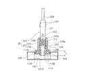
図1は、本発明の実施の形態における医療用管継手20の構成を説明する概要図である。
この医療用管継手20は、輸液や輸血を搬送する搬送路を構成する管の継ぎ手であって、主送液路に側注路を設ける混注ポート1000、三方活栓3000およびメスルアー部付設管などのいずれにも接続でき、互いの係合を固定可能、即ち、ロック可能な管継手20である。
Embodiments of the present invention will be described in detail with reference to the drawings.
FIG. 1 is a schematic diagram illustrating the configuration of a medical pipe joint 20 according to an embodiment of the present invention.
The medical pipe joint 20 is a joint of a pipe constituting a transport path for transporting infusions and blood transfusions, such as a
ここで、混注ポート1000、三方活栓3000及びメスルアー部付設管の構成について説明する。
先にも述べたように、混注ポート1000は、その中央の管壁に設けられた平坦な弁座部1102に貫通孔(不図示)が形成されてなる管状のポート本体1010と、弾性材料からなり上記貫通孔(不図示)を遮蔽するように弁座部102上に配されたディスク状の弁体1011と、この弁体1011をポート本体1010に装着し固定する筒状で中央に透孔1012が配されたカバー体1120及び当該カバー体1120を固定する両端に爪が配されたコの字状のカバーホルダー1013から構成されている。
Here, the configuration of the
As described above, the
上記弁体1011の中央には、外部から細管を挿入できるようにスリット部1111が形成されており、また、カバー体1120には、前記弁体1011に挿入した細管の接続状態を固定するために、前記筒状の筐体の側壁から径方向外方に突出する1対の突起1126が設けられている。
また、三方活栓3000は、先に述べたように、円筒状の本体部3001と、この本体部3001の周面から三方へとそれぞれ延出された第1分岐管3011、第2分岐管3012及びロックナットが付設された第3分岐管3013と、本体部3001に回転自在に挿設された円柱状で内部に三方に貫通孔が配された通路切換部3002とから構成される。
In the center of the
Further, as described above, the three-
第1分岐管3011及び第2分岐管3012は、ISO−594(規格)に準じて設計がなされており、端部から遠ざかるにつれその内径が漸減するいわゆるメスルアー部となっており、さらに上記端部の外周には、おねじ部3011a及びおねじ部3012aが刻設されている。
また、上述したように、メスルアー部付設管は、第1分岐管3011と同一構造を端部に採用した単管である。
(医療用管継手20の構成)
この医療用管継手20は、図1に示すように、輸液または血液搬送路を有する規格の異なる医療器具に3通りの方法で接続することができる汎用性の高い管継手であって、筒状の接続補助体23に管体220が挿設されてなる。
The
In addition, as described above, the female luer-attached pipe is a single pipe adopting the same structure as that of the
(Configuration of medical pipe joint 20)
As shown in FIG. 1, the medical pipe joint 20 is a highly versatile pipe joint that can be connected to a medical device having different infusion standards or blood transport paths by three methods, and has a cylindrical shape. The
管体220は、硬質で円筒状の主管部221の第1端部にルアー部224が配され、前記第1端部の周面に環状リブ223が配設され、主管部221の外表面において管軸に沿って伸びる一対の第1ストライプリブ222が配設され、さらに、主管部221のもう一方の第2端部の近傍に、第1ストライプリブ222に対して周方向に90度傾けたところに管軸に沿って伸びる一対の第2ストライプリブ225が配設され、環状リブ223と第1ストライプリブ222との間に巻きバネ211が周設され、さらに、主管部221の第2端部に軟質な連絡管226が接続されてなる。
The
第1ストライプリブ222及び第2ストライプリブ225は、上記管軸の直交方向における幅及び主管部221の外表面からの高さが同一となっている。
巻きバネ211のバネ定数は、10N/mmに設定されている。
接続補助体23は、筒状の本体部235の第1端部に、カバー体1120に被せられてこれに係合するキャップカバー部230が配されてなる。
The
The spring constant of the winding
The connection
このキャップカバー部230には、その内周にカバー体1120の一対の突起1126と係合する一対の溝部239が配されている。
本体部235は、その内径が前記主管部221の外径よりも僅かに大きい径小部236と、内径が径小部236よりも大きく、かつ、巻きバネ211の最大径より小さい径大部236aと、最小内径が径小部236の内径よりも大きいめねじ部238とが、その第2端部から第1端部にかけてこの順で配設されており、径小部236の内面には、さらに、管軸に沿って、第1ストライプリブ222及び第2ストライプリブ225が通過可能な一対の溝部237が刻設されている。
The
The
図1の接続方法(I)に示すように、管継手20を混注ポート1000に接続する場合には、管継手20の接続補助体23をルアー部224の位置する方向へと付勢しながらルアー部224を弁体1011のスリット部1111に挿入し、ルアー部224がカバー体1120の透孔1012の縁部に当接すると共に、接続補助体23をカバー体1120に密着させC1方向に捩ることにより、混注ポート1000の突起1126が管継手20の溝部239に突入し、混注ポート1000と管継手20との位置が固定され、確実に接続される。
As shown in the connection method (I) of FIG. 1, when the pipe joint 20 is connected to the
このとき、第1ストライプリブ222は溝部237の中にあり、主管部221の管軸を回転軸とする接続補助体23と管体220との相対変化が防止される。つまり、接続補助体23が捩られると、管体220も捩られる構成となっている。
ルアー部224のスリット部1111への挿入において、穿刺抵抗が最大で30Nが発生するため、この反力を受けて巻きバネ211が縮み、さらに、接続補助体23に対して管体220が後退するが、この後退量を考慮し、巻きバネ211に力が作用していない無負荷時における接続補助体23からのルアー部224の出代(図2示すL)を8mmに設定している。
At this time, the
When the
このため、接続完了時において、図2に示すように、弁体1011のスリット部1111に液密シール性能を確保するのに十分な深さまでルアー部224を挿入することができる。
同様に、接続方法(II)に示すように、管継手20を、例えば、三方活栓3000に接続する場合には、管継手20のルアー部224を、例えば、第1分岐管3011の開口部3011bに挿入すると共に、接続補助体23を第1分岐管3011に密着させC1方向に捩ることにより、三方活栓3000のおねじ部3011aが管継手20のめねじ部238に螺合し、三方活栓3000と管継手20との位置がロックされる。
For this reason, when the connection is completed, as shown in FIG. 2, the
Similarly, as shown in the connection method (II), when connecting the pipe joint 20 to, for example, the three-
このとき、接続方法(I)と同様に、上記接続の際に、接続補助体23をルアー部224側に付勢して、ルアー部224を第1分岐管3011の開口部3011bに挿入するが、ルアー部224が開口部3011bに完全に入りきるとそれ以上の挿入ができなくなり、巻きバネ211が縮み、接続補助体23に対して管体220が後退する。
このとき、第1分岐管3011のおねじ部3011aが、管継手20のめねじ部238に近づき、さらに、上記付勢に伴って、接続補助体23を捩ることにより、めねじ部238とおねじ部3011aが螺合し、その係合度合いを深めて行き、最終的には、図3のD部に示すように、係合が解除されない程度まで深く螺合される。
At this time, similarly to the connection method (I), the connection
At this time, the male threaded
この螺合が完了したとき、接続補助体23に対する管体220の後退量は、接続方法(I)よりも大きい。
さらに、接続方法(III)に示すように、管継手20の接続補助体23を主管部221から連絡管226上に移動させて、接続補助体23を用いずに、管体220を三方活栓3000に接続、即ち、スリップ接続することができる。
(バネの設定について)
本実施の形態では、巻きバネ211のバネ定数を10N/mmに設定したが、これに限らず5N/mm以上、20N/mm以下の範囲で設定すればよい。
When this screwing is completed, the retraction amount of the
Further, as shown in connection method (III), the connection
(About spring setting)
In the present embodiment, the spring constant of the winding
バネ定数の設定値を5N/mm、10N/mm及び20N/mmに変化させた場合における、図2及び図3におけるバネの出代Lの設定値及び無負荷時、混注ポート装着時及び三方活栓3000装着時(メスルアー部装着時)におけるバネに作用する力を表1に示す。 When the set value of the spring constant is changed to 5 N / mm, 10 N / mm and 20 N / mm, the set value of the spring allowance L in FIGS. 2 and 3, no load, when the mixed injection port is mounted, and the three-way stopcock Table 1 shows the force acting on the spring when 3000 is attached (when the female luer part is attached).

一方、巻きバネ211のバネ定数を20N/mmを超えて設定すると、バネの反力が90Nを超えてしまい、係合時における操作力が大きく扱い難くなってしまい実用面で問題が生じる。
さらに、ルアー部224における係合は、テーパー同士の係合となっており、バネの反力を強めすぎると係合を解除する際に外れなくなるいわゆる噛み込みが生じる場合があるため、バネ定数を20N/mm以下とすることで、このような不都合が生じないようにすることができる。
On the other hand, if the spring constant of the winding
Furthermore, the engagement at the
以上より、巻きバネ211のバネ定数は、5N/mm以上、20N/mm以下が好ましい。
(まとめ)
本実施の形態の医療用管継手20は、混注ポート1000や三方活栓3000などの接続対象器具に、管継手20をルアーロック接続する場合、接続補助体23を付勢してルアー部224をスリット部1111及び開口部3011bに挿入したとき、挿入に伴い接続補助体23に対する管体220の位置が後退し、しかも、この後退が接続対象器具毎に係合に適した位置まで行われるため、いずれの接続対象器具であっても確実に係合がなされる。
From the above, the spring constant of the winding
(Summary)
When the pipe joint 20 is connected to a connection object such as the
なお、本実施の形態の医療用管継手20では、接続補助体23及び管体220間の係合に巻きバネ211を介在させていたが、接続補助体23に対して管体220が後退する際に互いの反力を与えるように構成された弾性体であればよく、例えば、円筒状のゴムであってもよい。また、仮にバネであったとしても、その形状が巻きバネに限るものではなく、例えば、蛇腹状であってもよいし、板バネであってもよい。
In the medical pipe joint 20 of the present embodiment, the winding
また、本実施の形態の医療用管継手20では、環状リブ223と第1ストライプリブ222とで巻きバネ211を挟むことにより巻きバネ211を係止しているが、このような構成に限定するものではなく、例えば、環状リブ223の管軸方向の長さを本実施の形態よりも長くし、この部分に巻きバネ211の巻き線が丁度嵌合する溝を刻設しておき、この部位に巻きバネ211の片側の端部のみを嵌合させ、巻きバネ211のもう片方の端部は、フリーにしておく構成であってもよい。
Moreover, in the medical pipe joint 20 of this Embodiment, although the winding
このような構成を採用する場合、巻きバネ211を係止する目的としては、第1ストライプリブ222は不要となる。
When such a configuration is employed, the
本願発明は、患者に輸液や輸血を行う主送液路を構成する医療用器具に適用が可能である。 The present invention can be applied to a medical instrument that constitutes a main liquid supply path for performing infusion or blood transfusion to a patient.
20 管継手
23 接続補助体
102 弁座部
211 バネ
220 管体
221 主管部
222 ストライプリブ
223 環状リブ
224 ルアー部
225 ストライプリブ
226 連絡管
230 キャップカバー部
235 本体部
236 径小部
236a 径大部
237 溝部
238 めねじ部
239 溝部
1000 混注ポート
1010 ポート本体
1011 弁体
1013 カバーホルダー
1102 弁座部
1111 スリット部
1120 カバー体
1126 突起
3000 三方活栓
3001 本体部
3002 通路切換部
3011a おねじ部
3011b 開口部
3012a おねじ部
3011 第1分岐管
3012 第2分岐管
3013 第3分岐管
20 pipe joint 23 connection auxiliary body 102
Claims (7)
前記弁体及び前記連結孔のいずれにも嵌入されるルアー部を先端に有する管筒体と、
前記管筒体を前記第1の管構造体及び前記第2の管構造体に連結固定する際に用いるものであって、前記第1の管構造体に形成された第1被係止部と係合する第1係止部と、前記第2の管構造体に形成された第2被係止部と係合する第2係止部とを有する連結補助具と、
前記連結補助具に対して、前記管筒体を遊挿状態で保持する弾性部材とを備え、
前記管筒体の前記ルアー部を前記弁体に嵌入して、前記第1係止部を前記第1被係止部に係合した状態と、同ルアー部を前記連結孔に嵌入して、前記第2係止部を前記第2被係止部に係合する状態との2状態間で生じる、前記管筒体と前記連結補助具との相対的位置のくい違いを、前記連結補助具に対して前記管筒体が前記管筒体の軸方向へと移動することにより吸収すると共に、前記2状態において、前記管筒体が、前記弾性部材から前記ルアー部の嵌入方向へと向かう反力を受けることを特徴とする医療用管継手。 In the first pipe structure and the second pipe structure that are provided with a liquid feed path and are formed according to different standards, the liquid feed path of the first pipe structure serves as a pipe connection mechanism. A medical pipe joint that can be connected to any of two types in which a valve body is disposed and a connection hole is arranged in the liquid feeding path of the second pipe structure,
A tubular body having a luer part fitted at either end of the valve body and the connection hole;
A first locking portion formed on the first tube structure, wherein the tube tube body is used for connecting and fixing the tube structure to the first tube structure and the second tube structure; A connection aid having a first locking portion to be engaged and a second locking portion to be engaged with a second locked portion formed in the second tube structure;
An elastic member that holds the tubular body in a loosely inserted state with respect to the connection aid,
Inserting the luer part of the tubular body into the valve body, engaging the first locking part with the first locked part, and inserting the luer part into the connecting hole; A difference in the relative position between the tubular body and the connection aid that occurs between the two states of engaging the second engagement portion with the second engagement portion is described as follows. In contrast, the tubular body is absorbed by moving in the axial direction of the tubular body, and in the two states, the tubular body is moved from the elastic member toward the fitting direction of the luer portion. Medical pipe joint characterized by receiving force.
前記ルアー部の外径が漸増する方向を漸増方向とするとき、
前記管筒体の外周面には、第1突起と第2突起とが、前記漸増方向においてこの順に互いに距離をおいて配設され、
前記弾性部材は、巻きバネであって、前記管筒体における前記第1突起と前記第2突起との間に周設されていることを特徴する請求項1に記載の医療用管継手。 The connection aid is cylindrical and is provided around the tubular body,
When the direction in which the outer diameter of the luer portion gradually increases is the gradually increasing direction,
On the outer peripheral surface of the tubular body, a first protrusion and a second protrusion are disposed at a distance from each other in this order in the gradually increasing direction,
2. The medical pipe joint according to claim 1, wherein the elastic member is a wound spring and is provided between the first protrusion and the second protrusion in the tubular body.
前記管筒体の外周には、前記第2突起よりもさらに前記漸増方向側に、前記溝を通過可能な第3の突起を有することを特徴とする請求項5に記載の医療用管継手。 Furthermore, a groove is disposed along the tube axis on the inner wall of the connection aid,
6. The medical pipe joint according to claim 5, wherein a third protrusion that can pass through the groove is further provided on the outer periphery of the tubular body on the further increasing direction side than the second protrusion.
Priority Applications (1)
| Application Number | Priority Date | Filing Date | Title |
|---|---|---|---|
| JP2006206564A JP4802914B2 (en) | 2006-07-28 | 2006-07-28 | Medical pipe joint and line used for transporting infusion or blood using the same |
Applications Claiming Priority (1)
| Application Number | Priority Date | Filing Date | Title |
|---|---|---|---|
| JP2006206564A JP4802914B2 (en) | 2006-07-28 | 2006-07-28 | Medical pipe joint and line used for transporting infusion or blood using the same |
Publications (2)
| Publication Number | Publication Date |
|---|---|
| JP2008029606A JP2008029606A (en) | 2008-02-14 |
| JP4802914B2 true JP4802914B2 (en) | 2011-10-26 |
Family
ID=39119623
Family Applications (1)
| Application Number | Title | Priority Date | Filing Date |
|---|---|---|---|
| JP2006206564A Expired - Fee Related JP4802914B2 (en) | 2006-07-28 | 2006-07-28 | Medical pipe joint and line used for transporting infusion or blood using the same |
Country Status (1)
| Country | Link |
|---|---|
| JP (1) | JP4802914B2 (en) |
Families Citing this family (4)
| Publication number | Priority date | Publication date | Assignee | Title |
|---|---|---|---|---|
| JP5290630B2 (en) * | 2007-06-05 | 2013-09-18 | ニプロ株式会社 | Medical connector and manufacturing method thereof |
| JP5489081B2 (en) * | 2008-12-26 | 2014-05-14 | ニプロ株式会社 | Medical connector |
| JP2013158598A (en) * | 2012-02-08 | 2013-08-19 | Jms Co Ltd | Syringe |
| CN109526944A (en) * | 2019-01-07 | 2019-03-29 | 成都泰盟软件有限公司 | A kind of exhaust bubble structure in Perfused isolated heart system |
Family Cites Families (6)
| Publication number | Priority date | Publication date | Assignee | Title |
|---|---|---|---|---|
| JPS5987840U (en) * | 1982-12-07 | 1984-06-14 | 住友ベークライト株式会社 | luer lock connector |
| JPH0190550U (en) * | 1987-12-07 | 1989-06-14 | ||
| CA2458531C (en) * | 2001-10-09 | 2008-08-05 | Halkey-Roberts Corporation | Male luer valve |
| JP4106541B2 (en) * | 2002-08-26 | 2008-06-25 | 日本シャーウッド株式会社 | Lock type connector |
| JP2004254789A (en) * | 2003-02-25 | 2004-09-16 | Jms Co Ltd | Medical instrument |
| JP4289046B2 (en) * | 2003-07-04 | 2009-07-01 | 株式会社ジェイ・エム・エス | Medical syringe |
-
2006
- 2006-07-28 JP JP2006206564A patent/JP4802914B2/en not_active Expired - Fee Related
Also Published As
| Publication number | Publication date |
|---|---|
| JP2008029606A (en) | 2008-02-14 |
Similar Documents
| Publication | Publication Date | Title |
|---|---|---|
| US11697013B2 (en) | Medical fluid coupling and a latching connector for establishing a fluid communication between two systems | |
| US10183158B2 (en) | Connecting structure for medical use | |
| JP4971728B2 (en) | Connector connection structure | |
| EP3415194B1 (en) | Connecting structure for medical use | |
| CN109562253B (en) | Needle assembly with valve and indwelling needle assembly | |
| JP2007296317A (en) | Male luer connector | |
| US11872366B2 (en) | Connecting structure for medical use | |
| JP4848881B2 (en) | Medical pipe joint and line used for transporting infusion or blood using the same | |
| KR101136784B1 (en) | Medical use syringe | |
| JP4802914B2 (en) | Medical pipe joint and line used for transporting infusion or blood using the same | |
| JP5041920B2 (en) | Lock connector | |
| US10220198B2 (en) | Connection device for a medical fluid conduit system | |
| US11452856B2 (en) | Medical device | |
| US11027110B2 (en) | Medical connector | |
| JP2010142363A (en) | Medical valve | |
| WO2019187838A1 (en) | Medical instrument | |
| WO2022163311A1 (en) | Medical connector | |
| KR100537777B1 (en) | One-touch tube connector | |
| JP7162053B2 (en) | medical connector | |
| WO2023074314A1 (en) | Pipe joint | |
| JP2012236096A (en) | Male luer connector | |
| JP2024045522A (en) | Male Connector |
Legal Events
| Date | Code | Title | Description |
|---|---|---|---|
| A621 | Written request for application examination |
Free format text: JAPANESE INTERMEDIATE CODE: A621 Effective date: 20090701 |
|
| TRDD | Decision of grant or rejection written | ||
| A01 | Written decision to grant a patent or to grant a registration (utility model) |
Free format text: JAPANESE INTERMEDIATE CODE: A01 Effective date: 20110712 |
|
| A01 | Written decision to grant a patent or to grant a registration (utility model) |
Free format text: JAPANESE INTERMEDIATE CODE: A01 |
|
| A977 | Report on retrieval |
Free format text: JAPANESE INTERMEDIATE CODE: A971007 Effective date: 20110714 |
|
| A61 | First payment of annual fees (during grant procedure) |
Free format text: JAPANESE INTERMEDIATE CODE: A61 Effective date: 20110725 |
|
| R150 | Certificate of patent (=grant) or registration of utility model |
Free format text: JAPANESE INTERMEDIATE CODE: R150 |
|
| FPAY | Renewal fee payment (prs date is renewal date of database) |
Free format text: PAYMENT UNTIL: 20140819 Year of fee payment: 3 |
|
| R250 | Receipt of annual fees |
Free format text: JAPANESE INTERMEDIATE CODE: R250 |
|
| LAPS | Cancellation because of no payment of annual fees |