JP5289552B2 - SIM card connector - Google Patents
SIM card connector Download PDFInfo
- Publication number
- JP5289552B2 JP5289552B2 JP2011501716A JP2011501716A JP5289552B2 JP 5289552 B2 JP5289552 B2 JP 5289552B2 JP 2011501716 A JP2011501716 A JP 2011501716A JP 2011501716 A JP2011501716 A JP 2011501716A JP 5289552 B2 JP5289552 B2 JP 5289552B2
- Authority
- JP
- Japan
- Prior art keywords
- tray
- sim card
- guide groove
- case
- card connector
- Prior art date
- Legal status (The legal status is an assumption and is not a legal conclusion. Google has not performed a legal analysis and makes no representation as to the accuracy of the status listed.)
- Expired - Fee Related
Links
Images


Classifications
-
- H—ELECTRICITY
- H01—ELECTRIC ELEMENTS
- H01R—ELECTRICALLY-CONDUCTIVE CONNECTIONS; STRUCTURAL ASSOCIATIONS OF A PLURALITY OF MUTUALLY-INSULATED ELECTRICAL CONNECTING ELEMENTS; COUPLING DEVICES; CURRENT COLLECTORS
- H01R12/00—Structural associations of a plurality of mutually-insulated electrical connecting elements, specially adapted for printed circuits, e.g. printed circuit boards [PCB], flat or ribbon cables, or like generally planar structures, e.g. terminal strips, terminal blocks; Coupling devices specially adapted for printed circuits, flat or ribbon cables, or like generally planar structures; Terminals specially adapted for contact with, or insertion into, printed circuits, flat or ribbon cables, or like generally planar structures
- H01R12/70—Coupling devices
- H01R12/71—Coupling devices for rigid printing circuits or like structures
-
- G—PHYSICS
- G06—COMPUTING OR CALCULATING; COUNTING
- G06K—GRAPHICAL DATA READING; PRESENTATION OF DATA; RECORD CARRIERS; HANDLING RECORD CARRIERS
- G06K7/00—Methods or arrangements for sensing record carriers, e.g. for reading patterns
- G06K7/0013—Methods or arrangements for sensing record carriers, e.g. for reading patterns by galvanic contacts, e.g. card connectors for ISO-7816 compliant smart cards or memory cards, e.g. SD card readers
- G06K7/0021—Methods or arrangements for sensing record carriers, e.g. for reading patterns by galvanic contacts, e.g. card connectors for ISO-7816 compliant smart cards or memory cards, e.g. SD card readers for reading/sensing record carriers having surface contacts
Landscapes
- Engineering & Computer Science (AREA)
- Artificial Intelligence (AREA)
- Computer Vision & Pattern Recognition (AREA)
- Physics & Mathematics (AREA)
- General Physics & Mathematics (AREA)
- Theoretical Computer Science (AREA)
- Coupling Device And Connection With Printed Circuit (AREA)
Description
本発明は、移動無線端末に加入者識別モジュール(SIM)カードを実装するためのコネクタに関し、特に、薄いが強度が高いSIMカードコネクタに関する。 The present invention relates to a connector for mounting a subscriber identity module (SIM) card in a mobile radio terminal, and more particularly to a thin but high strength SIM card connector.
移動無線端末の使用方法には、時分割多重接続部方法である移動通信用グローバルシステム(GSM)、時分割多重アクセス(TDMA)、符号分割多数アクセス(CDMA)等、いくつかの方法がある。特に、欧州で使用されるGSMは基本的に、移動無線端末のユーザの識別用にSIMカードを採用している。 There are several methods for using a mobile radio terminal, such as a mobile communication global system (GSM), time division multiple access (TDMA), and code division multiple access (CDMA), which are time division multiple access method. In particular, GSM used in Europe basically employs a SIM card for user identification of mobile radio terminals.
SIMカードは、加入者の個人データ、電話番号、ネットワーク関係等の情報を含み、長さが約2cm、幅が約1cm、厚みが約1mmの寸法である、集積回路(IC)が内蔵されたカードである。個人データ認識手段としてのSIMカードが携帯電話に挿入されると、携帯電話は電話番号が登録され、対応するユーザが使用することができる。このような優れた携帯性、使用の利便性及びセキュリティを有するので、SIMカードは電子商取引等で実際に使用されている。 The SIM card contains information such as the subscriber's personal data, telephone number, and network information, and has an integrated circuit (IC) that is approximately 2 cm in length, approximately 1 cm in width, and approximately 1 mm in thickness. Card. When a SIM card as personal data recognition means is inserted into a mobile phone, the mobile phone is registered with a phone number and can be used by the corresponding user. Because of such excellent portability, convenience of use and security, SIM cards are actually used in electronic commerce and the like.
図7は、SIMカードを移動無線端末に実装するために使用される従来のコネクタを示す。 FIG. 7 shows a conventional connector used for mounting a SIM card on a mobile radio terminal.
この図によれば、従来のSIMカードコネクタ100は、電気端子がSIMカードと電子的に接続した状態で配列された上板111と、上板111の下部で上板111を取り囲むハウジング112により構成され、一側に開放した箱の形態であるケース110と、ケース110に分離可能に接続された合成樹脂製の引き出し型トレイ120とを具備する。SIMカードがトレイ120に載置され、トレイ120がケース110に挿入されると、SIMカードは移動端末と電気接続することができる。
According to this figure, a conventional
しかし、箱状のケース110及びケース110に挿入された樹脂製トレイ120により構成されたこのような従来のSIMカードコネクタ100によれば、SIMカードの厚みにケース110の上板111の厚み、ハウジング112の底部の厚み、トレイ120の底部の厚みがさらに追加されるので、全厚みが大きくなってしまう。
However, according to such a conventional
近年、技術が進歩しており、移動端末は、より良好な携帯性のために多機能及び高性能を維持しながら、より小さく、より薄く、より軽量になりつつある。すなわち、この従来のSIMカードコネクタは、このような傾向と相反する。 In recent years, technology has advanced, and mobile terminals are becoming smaller, thinner and lighter while maintaining multiple functions and high performance for better portability. That is, this conventional SIM card connector is contrary to such a tendency.
また、柔らかい樹脂で薄く作られた従来のトレイ120は、ケース110への挿入中や挿入後に、ケース110の内壁からの圧力により変形しがちである。例えば、柔らかいトレイ120底側が横の圧力により曲がる場合、トレイ120に挿入されたSIMカードは、上板111に形成された電気端子との接続が不十分になるおそれがあるので、接続不良を生ずるおそれがある。
In addition, the
従って、本発明は、上述の問題に鑑みてなされたものであり、移動無線端末にSIMカードをしっかりと実装するためにトレイを使用しつつ、従来のコネクタと比較して厚みを薄くできる、移動端末にSIMカードを実装するためのコネクタを提供することを目的とする。 Therefore, the present invention has been made in view of the above-mentioned problems, and the thickness can be reduced as compared with the conventional connector while using the tray to securely mount the SIM card on the mobile radio terminal. An object is to provide a connector for mounting a SIM card on a terminal.
特に、本発明は、トレイの作動部の強度を向上させながら、ケースの部品を最小にすることによりSIMカードコネクタの厚みを小さくすることを目的とする。 In particular, it is an object of the present invention to reduce the thickness of a SIM card connector by minimizing the case components while improving the strength of the operating portion of the tray.
本発明の別の目的は、トレイの強度を向上させることにより、トレイの変形を防止することである。 Another object of the present invention is to prevent deformation of the tray by improving the strength of the tray.
本発明のさらに別の目的は、SIMカードコネクタの作動部品の摩擦を低減することにより、トレイの引き込み(drawn in)及び引き出しの作動効率を上げると共に、SIMカードコネクタの耐久性を向上させることである。 Still another object of the present invention is to improve the durability of the SIM card connector while improving the efficiency of drawing and pulling in the tray by reducing the friction of the working parts of the SIM card connector. is there.
さらに、本発明の別の目的は、トレイに載置されケースに挿入されたSIMカードを正しい位置で電気接続を確実に達成できるようにトレイの作動範囲を制限すると共に、トレイの出し入れを検知することによりSIMカードを利便性よく接続し分離することである。 Furthermore, another object of the present invention is to limit the operating range of the tray and to detect the insertion and removal of the tray so that the SIM card placed on the tray and inserted into the case can be reliably connected to the correct position. Thus, the SIM card is connected and separated with good convenience.
また、本発明の別の目的は、トレイが引き出される際にトレイがケースから容易に脱落するのを防止することである。 Another object of the present invention is to prevent the tray from easily falling off the case when the tray is pulled out.
さらに、本発明の別の目的は、携帯端末の回路基板に薄いSIMカードコネクタを容易に且つしっかりと実装することである。 Furthermore, another object of the present invention is to easily and securely mount a thin SIM card connector on a circuit board of a portable terminal.
本発明によれば、上述及び別の目的は、SIMカードに電気接続された接続基板及び接続基板の両側に形成された案内溝ユニットにより構成されたケースと、SIMカードを載置する際に、摺動で案内溝ユニットに接続されるトレイとを具備するSIMカードコネクタを提供することにより達成される。 According to the present invention, the above and other objects are as follows: when the SIM card is placed on the case formed by the connection board electrically connected to the SIM card and the guide groove unit formed on both sides of the connection board; This is accomplished by providing a SIM card connector having a tray that is slidably connected to the guide groove unit.
ケースの案内溝ユニットは、接続基板に形成された接続端子を有する金属枠の両縁を曲げることにより形成することができる。接続基板は、金属枠を合成樹脂でコーティングすることにより形成される。接続端子を連結する連結片(runner)は、接続端子を互いに絶縁するために穿孔され、除去される。 The guide groove unit of the case can be formed by bending both edges of a metal frame having connection terminals formed on the connection substrate. The connection substrate is formed by coating a metal frame with a synthetic resin. A runner connecting the connecting terminals is drilled and removed to insulate the connecting terminals from each other.
トレイは、強度を向上させるために金属製であり、SIMカードを載置する底面と、摺動で案内溝ユニットと接続するために底面の縁を曲げて形成された側壁とを有する。 The tray is made of metal in order to improve the strength, and has a bottom surface on which the SIM card is placed, and a side wall formed by bending the edge of the bottom surface so as to slide and connect to the guide groove unit.
以下、添付図面を参照して、本発明の典型的な一実施形態を詳細に説明する。 Hereinafter, an exemplary embodiment of the present invention will be described in detail with reference to the accompanying drawings.
本明細書で言及される加入者識別モジュール(SIM)は、移動端末に取り付けられ、一面に電気接続用のICチップ端子を具備する薄い板の形態のさまざまなカードを一般に指す。SIMカードは、USIM等の一般的なSIMカードのみならず、他の派生的なカードをも含む。 The subscriber identity module (SIM) referred to herein generally refers to various cards in the form of thin plates that are attached to a mobile terminal and have IC chip terminals for electrical connection on one side. The SIM card includes not only a general SIM card such as a USIM but also other derivative cards.
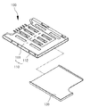
図1は、本発明の一実施形態に係るSIMカードコネクタを示す斜視図である。 FIG. 1 is a perspective view showing a SIM card connector according to an embodiment of the present invention.
SIMカードコネクタ1は、移動端末に実装されるケース10と、SIMカードを載置するものとしてケース10に接続されたトレイ20とを具備する。ケース10は、板の形態の接続基板11と、摺動でトレイ20に接続されるよう接続基板11の両側に形成された案内溝ユニット12とによって構成される。
The
接続基板11の中央部には、複数の接続端子11a(図2参照)が、SIMカードの端子に接続されるように後退して形成されている。さらに、各接続端子11aに対応するリード11b(図2参照)が、移動端末の回路基板上の電路(図示せず)に接続されるよう、SIMカードの挿入入口で延びている。
A plurality of
案内溝ユニット12は、長手方向に沿って接続基板11の両側に形成されており、トレイ20の両側が案内溝ユニット12に沿って摺動するように、トレイ20の両側を囲む平坦なU形状の断面形状を有する。
The
上述の構造によれば、本実施形態に係るSIMカードコネクタ1は、SIMカードがトレイ20内で撓むことを防止することができる。また、トレイ20を受容するケース10はSIMカードに電気接続された接続基板11及び両側に形成された案内溝ユニット12を具備するので、従来使用されてきたハウジングを省略でき、それ故、SIMカードコネクタの厚みを小さくすることができる。
According to the above-described structure, the
図2は、図1に示されたSIMカードコネクタのケースを上から見た斜視図である。図3は、図2に示されたケースを下から見た斜視図である。 FIG. 2 is a perspective view of the SIM card connector case shown in FIG. 1 as viewed from above. FIG. 3 is a perspective view of the case shown in FIG. 2 as viewed from below.
接続面に形成された接続端子11aを有するケース10は、トレイ20が作動する案内溝ユニット12の強度を向上させるために、以下のように構成される。
The
ケース10は、接続端子11aと、案内溝ユニット12と、薄く押圧された基板の形態の金属枠Fを曲げ加工して形成された、後述する支持片とを具備する。接続基板11は、合成樹脂Pでコーティングされることにより、金属枠Fの中央に形成される。
The
より具体的には、ケース10は、以下のように構成され製造される。図4を参照すると、導電性を有する金属枠Fの一部に孔が開けられる(T)ことにより、接続端子11aが製造される。金属枠Fの一部としての接続端子11aは、連結片により互いに相互接続される。薄い樹脂層である接続層は、合成樹脂Pをインサート成形することにより、金属枠Fの中央に形成される。その後、連結片に孔を開けることにより、接続端子11aは互いに絶縁される。金属枠Fの両側が曲げられることにより、ケース10の長さに沿って案内溝ユニット12が形成される。
More specifically, the
このように金属枠Fを使用することにより、ケース10の強度は全体として増大する。特に、案内溝ユニット12は、トレイ20が頻繁に引き込み及び引き出しされることによる磨耗するので、案内溝ユニット12の強度の増大により、ケース10の堅牢性を向上させることができる。
By using the metal frame F in this way, the strength of the
また、別体の接続端子を挿入し固定することなく、接続端子11aを金属枠Fにより直接形成することができる。この結果、ケース10の製造を簡素化することができる。さらに、接続端子11aを実装する空間を節約することにより、ケース10をより薄く形成することができる。
Further, the
図5は、図1に示されたSIMカードコネクタのトレイを示す斜視図である。図6は、図5のトレイに取り付けられた金属枠F’を示す斜視図である。 FIG. 5 is a perspective view showing the tray of the SIM card connector shown in FIG. FIG. 6 is a perspective view showing the metal frame F ′ attached to the tray of FIG. 5.
案内溝ユニット12に摺動可能に接続されたトレイ20は、SIMカードが載置される底面21と、SIMカードの両側を取り囲むよう底面21の両縁から上方へ曲げられた側壁22とを具備する。すなわち、トレイ20は、摺動で案内溝ユニット12に接続されている。
The
トレイ20は挿入又は引き出しの間に印加される力により変形し得るので、このような変形を防止するためにトレイ20の材料として金属を使用することが好ましい。これによれば、SIMカードが載置されるトレイ20の底面21は、従来の柔らかい樹脂製のトレイよりも薄く形成されながら、外力に対してより抗することができる。
Since the
トレイ20の側壁22は、金属枠F’製の底面21の両縁を曲げ、この曲げた部分に合成樹脂を成形することにより、形成される。
The
この場合、トレイ20の合成樹脂製の側壁22が発生する摩擦が金属の場合よりも小さいので、トレイ20は、より円滑にケース10に対して引き込み及び引き出しすることができる。
In this case, since the friction generated by the synthetic
さらに、合成樹脂が側壁22にインサート成形されつつ、さまざまな所望の形態を詳細に形成することができる。従って、後述する凹部23及びロック部24を容易に実施することができる。
Furthermore, various desired forms can be formed in detail while the synthetic resin is insert-molded on the
トレイ20を挿入する接続基板11の内面には、トレイ20の挿入長さを制限する停止突起11cが形成される。
Stop
特に、トレイ20が所定長さだけ挿入されると、停止突起11cは、トレイ20の長さ方向に形成された押圧片12aの一端と接触することによりトレイ20の更なる挿入を防止する。このため、トレイ20に載置されたSIMカードの端子は、接続基板11の内面に形成された接続端子11aの下に配置される。従って、正しい位置でSIMカード及び接続基板11を互いに電気接続することができる。
In particular, when the
押圧片12aは、案内溝ユニット12の入口付近で内側へ曲げられた形成されている。押圧片12aと係合するための凹部23は、ケース10に挿入されたトレイ20を保持するように、トレイ20の側壁22の縦の両側に形成される。
The
押圧片12aは横たえた平坦なU形状により案内溝ユニット12の側壁を打ち抜くことにより形成されるので、押圧片12aの一端12bは、挿入されるトレイ20を向く。押圧片12aが案内溝ユニット12から内方へ曲げられるのに対し、一端12bは外方へ曲げられる。従って、押圧片12aは、案内溝ユニット12の内方へ弾性的に突出することにより、案内溝ユニット12内で移動するトレイ20の外壁を弾性的且つ緊密に支持する。
Since the
さらに、凹部23は停止突起11cに対応する位置でトレイ20の両側の内方へ形成されるので、トレイ20が停止突起11cの位置まで挿入完了し、SIMカードが接続端子11aと完全に接続されると、押圧片12aはその復元力で凹部23に嵌まる。
Further, since the
従って、トレイ20は、一旦完全に挿入されると、ユーザがトレイ20を引き出すまで振動又は衝撃によりケース10から分離せず、SIMカード及び接続端子11a間の接続を維持する。
Therefore, once the
また、押圧片12aが凹部23に接続されると、接続感がユーザに直接伝わるので、ユーザはトレイ20がケース10内の適正位置に挿入されていることを確認できる。
Further, when the
さらに、ロック部24は、押圧片12aの一端12bとの干渉によりケース10からの引き出されたトレイ20の分離を防止するために、トレイ20の側壁22の縦の両側に形成される。より具体的には、SIMカードを取り外すためにトレイ20がケース10から引き出されると、ロック部24は押圧片12aの一端12bと干渉するので、トレイ20はケース10から完全には分離しない。また、押圧片12aの一端12bがロック部24にロックされると、ユーザは、ロック感に気付き、トレイ20を過度に押圧することによるトレイ20の破壊を防止する。
Further, the
このため、ロック部24はトレイ20の側壁22の各縦の側面の一端に配置されると共に、トレイ20の長さに直交して押圧される支持面24aを有する。
Therefore, the
案内溝ユニット12の上面12c又は下面12dから外方へ半田付け用の支持片12eが突出するので、移動端末の回路基板に容易に実装される。
Since the
特に、支持片12eは、案内溝ユニット12の上面12cよりも上方へ又は下面12eよりも下方へ突出する。
In particular, the
この典型的な実施形態によれば、支持片12eは、金属枠F製の案内溝ユニット12を部分的に打ち抜くことにより形成され、接続面に形成された合成樹脂Pの厚みにより上方へ突出する。この結果、ケース10は、平坦である回路基板と表面接触することができるようになる。
According to this typical embodiment, the
この場合、金属に形成された支持片12eは、半田付けの間、加熱により変形しないので、従来の半田付け実装を使用してケース10を回路基板に固定することができる。
In this case, since the
本発明の好適な実施形態を例示目的で開示したが、当業者であれば、添付特許請求の範囲に開示された発明の範囲及び真髄から逸脱することなく、さまざまな変形、追加及び置換が可能であることを理解するであろう。 While preferred embodiments of the present invention have been disclosed for purposes of illustration, those skilled in the art may make various modifications, additions and substitutions without departing from the scope and spirit of the invention disclosed in the appended claims. You will understand that.
上述したように、本発明の実施形態に係るSIMカードコネクタは、SIMカードの撓みを防止するよう低い撓み強度を有するSIMカードを載置するための、薄く形成されたトレイを採用する。トレイに接続されたケースは、接続面と、接続面の両側に形成された案内溝ユニットとを具備するので、従来のSIMカードコネクタに使用されていたハウジングを省略でき、厚みを小さくできる。この結果、移動端末は、薄いSIMカードコネクタを採用することにより、より小型に形成できるので、移動端末の競争力が向上する。 As described above, the SIM card connector according to the embodiment of the present invention employs a thinly formed tray for mounting a SIM card having a low bending strength so as to prevent the SIM card from bending. Since the case connected to the tray includes a connection surface and guide groove units formed on both sides of the connection surface, the housing used in the conventional SIM card connector can be omitted, and the thickness can be reduced. As a result, the mobile terminal can be formed more compactly by adopting a thin SIM card connector, thereby improving the competitiveness of the mobile terminal.
より具体的には、接続面の両側に形成された案内溝ユニットはSIMカードコネクタのうち、最も厚い部分であるので、本発明の実施形態に係るSIMカードコネクタの厚みは、従来のSIMカードコネクタと比較して薄くできる。 More specifically, since the guide groove unit formed on both sides of the connection surface is the thickest portion of the SIM card connector, the thickness of the SIM card connector according to the embodiment of the present invention is the same as that of the conventional SIM card connector. It can be made thinner.
すなわち、本発明に実施形態に係るSIMカードコネクタは、合成樹脂製のみから製造される従来のSIMカードコネクタと比較して厚みを小さくすることができる。 That is, the SIM card connector according to the embodiment of the present invention can be reduced in thickness as compared with a conventional SIM card connector manufactured only from a synthetic resin.
さらに、ケースが金属枠への合成樹脂の射出成形により形成される場合、SIMカードコネクタは、強度低下を生ずることなく、従来のSIMカードコネクタよりも薄く形成することができる。 Furthermore, when the case is formed by injection molding of a synthetic resin into a metal frame, the SIM card connector can be formed thinner than a conventional SIM card connector without causing a decrease in strength.
ケース以外では、トレイが作動する案内溝ユニットが、高強度の金属製である。従って、案内溝ユニットは、トレイの作動により磨耗し難いので、耐久性が向上する。 Other than the case, the guide groove unit for operating the tray is made of high-strength metal. Therefore, since the guide groove unit is not easily worn by the operation of the tray, the durability is improved.
さらに、金属製のトレイは、従来のトレイよりも薄いばかりでなく、外部衝撃による変形にも抗する。 Furthermore, the metal tray is not only thinner than the conventional tray, but also resists deformation due to external impact.
合成樹脂がトレイの壁に成形される場合、案内溝ユニットに沿ってケースに対して引き込み及び引き出しされるトレイ及び壁間の摩擦が減少するので、動作を円滑にする。 When the synthetic resin is molded on the wall of the tray, the friction between the tray and the wall that is drawn into and pulled out of the case along the guide groove unit is reduced, so that the operation is facilitated.
壁にインサート成形された合成樹脂は、壁のさまざまな設計をより可能にする。 Synthetic resin insert-molded into the wall makes various wall designs more possible.
停止突起は、トレイに載置されたSIMカードが接続端子と正しく接続される位置でトレイの挿入を妨げるので、SIMカード及び移動端末間の電気接続が確保される。 Since the stop protrusion prevents the tray from being inserted at a position where the SIM card placed on the tray is correctly connected to the connection terminal, an electrical connection between the SIM card and the mobile terminal is ensured.
押圧片及び凹部が設けられる場合、トレイがケースに挿入されると、押圧片は凹部に嵌まる。従って、トレイはユーザの引き出す動作が無くては分離しないので、SIMカード及び移動端末間の電気接続が確保される。 When the pressing piece and the recess are provided, the pressing piece fits into the recess when the tray is inserted into the case. Therefore, since the tray is not separated without the user pulling out, the electrical connection between the SIM card and the mobile terminal is ensured.
また、トレイを挿入する際に、ユーザは、押圧片及び凹部間の接続感を通してトレイが適正な深さに挿入されたことに気付く。従って、ユーザは、SIMカードの接続及び分離をより容易に実行することができる。 Further, when inserting the tray, the user notices that the tray has been inserted to an appropriate depth through a feeling of connection between the pressing piece and the recess. Therefore, the user can more easily execute connection and disconnection of the SIM card.
その一方で、押圧片及びロック部が設けられる場合、SIMカードを取り外すためにトレイが引き出されると、ロック部は押圧片の一端により妨げられるので、ケースからのトレイの分離を防止できる。 On the other hand, when the pressing piece and the lock portion are provided, when the tray is pulled out to remove the SIM card, the locking portion is hindered by one end of the pressing piece, so that separation of the tray from the case can be prevented.
また、案内溝ユニットの上部又は下部で半田付け用の支持片が外方へ突出するので、半田付けにより移動端末の回路基板に支持片を都合よく固定することができる。 In addition, since the soldering support piece protrudes outward at the upper or lower portion of the guide groove unit, the support piece can be conveniently fixed to the circuit board of the mobile terminal by soldering.
1 SIMカードコネクタ
10 ケース
11 接続基板
11a 接続端子
11c 停止突起
12 案内溝ユニット
12a 押圧片
12e 支持片
20 トレイ
21 底面
22 側壁
23 凹部
24 ロック部
F 金属枠
DESCRIPTION OF
Claims (5)
前記ケースの前記案内溝ユニットは、前記接続基板に形成された接続端子を有する金属枠の両縁を曲げることにより形成され、
前記接続基板は、前記金属枠を合成樹脂でコーティングすることにより形成されており、
前記トレイは、強度を向上させるために金属製であると共に、該トレイに前記SIMカードを載置する底面と、摺動で前記案内溝ユニットと接続するために前記底面の両縁を曲げることにより形成された側壁とを具備し、
円滑な摺動を向上させるために、前記側壁に合成樹脂が取り付けられていることを特徴とするSIMカードコネクタ。 A case constituted by a connection board electrically connected to the SIM card and guide groove units formed on both sides of the connection board, and when the SIM card is placed, it is connected to the guide groove unit by sliding. A SIM card connector comprising a tray ,
The guide groove unit of the case is formed by bending both edges of a metal frame having connection terminals formed on the connection substrate,
The connection board is formed by coating the metal frame with a synthetic resin,
The tray is made of metal to improve the strength, and a bottom surface on which the SIM card is placed on the tray, and both edges of the bottom surface are bent to connect to the guide groove unit by sliding. A side wall formed,
A SIM card connector , wherein a synthetic resin is attached to the side wall in order to improve smooth sliding .
Applications Claiming Priority (3)
| Application Number | Priority Date | Filing Date | Title |
|---|---|---|---|
| KR10-2008-0028039 | 2008-03-26 | ||
| KR20080028039A KR101496458B1 (en) | 2008-03-26 | 2008-03-26 | Sim card connector |
| PCT/KR2009/001510 WO2009120014A2 (en) | 2008-03-26 | 2009-03-25 | Connector of sim card |
Publications (2)
| Publication Number | Publication Date |
|---|---|
| JP2011519464A JP2011519464A (en) | 2011-07-07 |
| JP5289552B2 true JP5289552B2 (en) | 2013-09-11 |
Family
ID=41114454
Family Applications (1)
| Application Number | Title | Priority Date | Filing Date |
|---|---|---|---|
| JP2011501716A Expired - Fee Related JP5289552B2 (en) | 2008-03-26 | 2009-03-25 | SIM card connector |
Country Status (6)
| Country | Link |
|---|---|
| US (1) | US8021175B2 (en) |
| JP (1) | JP5289552B2 (en) |
| KR (1) | KR101496458B1 (en) |
| CN (1) | CN101978560B (en) |
| TW (1) | TWM363699U (en) |
| WO (1) | WO2009120014A2 (en) |
Families Citing this family (29)
| Publication number | Priority date | Publication date | Assignee | Title |
|---|---|---|---|---|
| JP5457888B2 (en) * | 2010-03-04 | 2014-04-02 | 第一電子工業株式会社 | Card connector and card connector manufacturing method |
| KR101314636B1 (en) * | 2012-03-05 | 2013-10-14 | (주)우주일렉트로닉스 | Menufacturing Method For Connector Cover |
| JP2013222629A (en) | 2012-04-17 | 2013-10-28 | Jst Mfg Co Ltd | Connector for card |
| JP2013222631A (en) | 2012-04-17 | 2013-10-28 | Jst Mfg Co Ltd | Connector for card |
| CN202712528U (en) * | 2012-06-05 | 2013-01-30 | 番禺得意精密电子工业有限公司 | Electric connector |
| CN103594838B (en) * | 2012-08-14 | 2015-12-02 | 富士康(昆山)电脑接插件有限公司 | Electronic card coupler |
| JP5835239B2 (en) * | 2013-01-08 | 2015-12-24 | 山一電機株式会社 | Tray type card connector |
| KR102045292B1 (en) | 2013-01-21 | 2019-12-02 | 삼성전자주식회사 | Eletronic device for recognizing card insertion error and application method thereof |
| KR200473528Y1 (en) * | 2013-02-25 | 2014-07-09 | 주식회사 제이앤티씨 | A socket for SIM Card |
| EP2816439B1 (en) * | 2013-04-22 | 2018-10-03 | Huawei Device Co., Ltd. | Device for preventing deformation of communication card |
| KR101586255B1 (en) * | 2014-03-18 | 2016-01-18 | (주)우주일렉트로닉스 | Sim card socket |
| TWI548147B (en) * | 2014-06-06 | 2016-09-01 | Molex Inc | Card holding member and card connector |
| US9761971B2 (en) * | 2014-06-06 | 2017-09-12 | Molex, Llc | Card holding member and card connector, which prevents short-circuits, prevents damage and wear, enables easier handling, and improves reliability |
| TWI623159B (en) * | 2014-06-06 | 2018-05-01 | Molex Inc | Card holding member and card connector |
| JP6395557B2 (en) * | 2014-10-20 | 2018-09-26 | モレックス エルエルシー | Card holding member and card connector set |
| KR101596316B1 (en) * | 2015-02-03 | 2016-02-22 | 몰렉스 엘엘씨 | Card tray for electronic device and tray carrier assembly using the same |
| JP6325996B2 (en) | 2015-02-23 | 2018-05-16 | モレックス エルエルシー | Card holding member and card connector |
| JP1553879S (en) * | 2015-11-03 | 2016-07-11 | ||
| JP1552812S (en) * | 2015-11-03 | 2016-06-27 | ||
| JP1553611S (en) * | 2015-11-03 | 2016-07-11 | ||
| JP1552813S (en) * | 2015-11-04 | 2016-06-27 | ||
| JP1552814S (en) * | 2015-11-04 | 2016-06-27 | ||
| JP1552815S (en) * | 2015-11-06 | 2016-06-27 | ||
| KR101875903B1 (en) * | 2015-12-11 | 2018-08-03 | 몰렉스 엘엘씨 | Card tray for electronic device |
| CN106998023A (en) * | 2016-01-22 | 2017-08-01 | 富士康(昆山)电脑接插件有限公司 | Electric connector |
| CN108701921A (en) * | 2016-11-03 | 2018-10-23 | 华为技术有限公司 | Sim card holder and sim card |
| KR102514864B1 (en) * | 2016-11-08 | 2023-03-29 | 삼성전자주식회사 | Device for accommodating storage medium and electronic device with the same |
| CN108604755B (en) * | 2016-11-17 | 2020-08-14 | 华为技术有限公司 | Electronic equipment |
| JP2020024848A (en) * | 2018-08-07 | 2020-02-13 | シャープ株式会社 | Card tray and electronic equipment |
Family Cites Families (15)
| Publication number | Priority date | Publication date | Assignee | Title |
|---|---|---|---|---|
| JP3068754B2 (en) * | 1994-09-16 | 2000-07-24 | 松下電器産業株式会社 | Plug-in SIM connection device |
| SE516154C2 (en) * | 1999-06-14 | 2001-11-26 | Ericsson Telefon Ab L M | A card receiving device for a communication device as well as a communication device |
| JP4403040B2 (en) * | 2004-08-19 | 2010-01-20 | 日本圧着端子製造株式会社 | Card holder for SIM socket |
| JP4386811B2 (en) * | 2004-08-19 | 2009-12-16 | 日本圧着端子製造株式会社 | Memory card socket |
| JP2006215881A (en) | 2005-02-04 | 2006-08-17 | Otax Co Ltd | Memory card slot with malfunction prevention device |
| CN100546104C (en) | 2005-03-04 | 2009-09-30 | 日本电气株式会社 | card connector and electronic device |
| JP4138765B2 (en) * | 2005-03-08 | 2008-08-27 | 山一電機株式会社 | Tray type card connector |
| JP4167237B2 (en) | 2005-03-08 | 2008-10-15 | 山一電機株式会社 | Tray type card connector |
| CN1866634A (en) * | 2005-05-16 | 2006-11-22 | 富士康(昆山)电脑接插件有限公司 | Electronic card connector |
| JP4628183B2 (en) * | 2005-05-20 | 2011-02-09 | モレックス インコーポレイテド | Tray card socket |
| JP4571028B2 (en) * | 2005-07-11 | 2010-10-27 | 日本圧着端子製造株式会社 | Card connector |
| JP4489664B2 (en) * | 2005-08-29 | 2010-06-23 | Smk株式会社 | Memory card connector |
| CN2862507Y (en) * | 2005-12-29 | 2007-01-24 | 富港电子(东莞)有限公司 | Pull-out SIM card connector |
| JP5049003B2 (en) * | 2006-05-25 | 2012-10-17 | 第一電子工業株式会社 | Card Connector and Housing SubAssy Manufacturing Method |
| CN100585952C (en) * | 2006-05-25 | 2010-01-27 | 第一电子工业株式会社 | Card connector and method for producing rack assembly |
-
2008
- 2008-03-26 KR KR20080028039A patent/KR101496458B1/en not_active Expired - Fee Related
-
2009
- 2009-03-06 TW TW098203445U patent/TWM363699U/en not_active IP Right Cessation
- 2009-03-25 JP JP2011501716A patent/JP5289552B2/en not_active Expired - Fee Related
- 2009-03-25 CN CN2009801111422A patent/CN101978560B/en not_active Expired - Fee Related
- 2009-03-25 WO PCT/KR2009/001510 patent/WO2009120014A2/en not_active Ceased
-
2010
- 2010-09-24 US US12/889,940 patent/US8021175B2/en active Active
Also Published As
| Publication number | Publication date |
|---|---|
| WO2009120014A2 (en) | 2009-10-01 |
| WO2009120014A3 (en) | 2009-12-23 |
| TWM363699U (en) | 2009-08-21 |
| CN101978560A (en) | 2011-02-16 |
| US20110039442A1 (en) | 2011-02-17 |
| KR20090102533A (en) | 2009-09-30 |
| KR101496458B1 (en) | 2015-02-26 |
| CN101978560B (en) | 2013-08-28 |
| US8021175B2 (en) | 2011-09-20 |
| JP2011519464A (en) | 2011-07-07 |
Similar Documents
| Publication | Publication Date | Title |
|---|---|---|
| JP5289552B2 (en) | SIM card connector | |
| US8376764B1 (en) | Card connector | |
| US7682178B2 (en) | Surface contact card holder | |
| CN101030684B (en) | card connector | |
| US7780464B2 (en) | Surface contact card holder and portable electronic device using the same | |
| US7789691B2 (en) | Chip card retaining mechanism and printed circuit board module incorporating same | |
| US7409225B2 (en) | Dual connection device for memory mediums and mobile communication terminals with the same | |
| CN203225369U (en) | Connector used for card | |
| JP2004126877A (en) | Card holding structure | |
| US9002403B2 (en) | Portable terminal and wireless module | |
| US6527189B2 (en) | Card reader connector with removable extension bracket | |
| CN203225368U (en) | Connector used for card | |
| KR100587305B1 (en) | Card connection device of mobile communication terminal | |
| KR200235498Y1 (en) | IC card connector | |
| KR101135050B1 (en) | Connector of socket for sim card | |
| KR101586255B1 (en) | Sim card socket | |
| KR100919951B1 (en) | Sim card connector | |
| JP5218921B2 (en) | IC card connector | |
| KR101315675B1 (en) | Dual socket | |
| TWI455415B (en) | Chip card hoiding device and portable electronic device employing the same | |
| CN101752703B (en) | Socket connector for IC card | |
| JP2010040327A (en) | Connector for card | |
| KR101316847B1 (en) | Micro sd card socket and manufacturing method thereof | |
| JP2005149993A (en) | Card connector | |
| KR20140016561A (en) | Socket for subscriber identification module card |
Legal Events
| Date | Code | Title | Description |
|---|---|---|---|
| A621 | Written request for application examination |
Free format text: JAPANESE INTERMEDIATE CODE: A621 Effective date: 20120203 |
|
| A977 | Report on retrieval |
Free format text: JAPANESE INTERMEDIATE CODE: A971007 Effective date: 20130214 |
|
| A131 | Notification of reasons for refusal |
Free format text: JAPANESE INTERMEDIATE CODE: A131 Effective date: 20130218 |
|
| A521 | Request for written amendment filed |
Free format text: JAPANESE INTERMEDIATE CODE: A523 Effective date: 20130416 |
|
| TRDD | Decision of grant or rejection written | ||
| A01 | Written decision to grant a patent or to grant a registration (utility model) |
Free format text: JAPANESE INTERMEDIATE CODE: A01 Effective date: 20130509 |
|
| A61 | First payment of annual fees (during grant procedure) |
Free format text: JAPANESE INTERMEDIATE CODE: A61 Effective date: 20130604 |
|
| R150 | Certificate of patent or registration of utility model |
Ref document number: 5289552 Country of ref document: JP Free format text: JAPANESE INTERMEDIATE CODE: R150 |
|
| R250 | Receipt of annual fees |
Free format text: JAPANESE INTERMEDIATE CODE: R250 |
|
| R250 | Receipt of annual fees |
Free format text: JAPANESE INTERMEDIATE CODE: R250 |
|
| R250 | Receipt of annual fees |
Free format text: JAPANESE INTERMEDIATE CODE: R250 |
|
| R250 | Receipt of annual fees |
Free format text: JAPANESE INTERMEDIATE CODE: R250 |
|
| LAPS | Cancellation because of no payment of annual fees |