JP5288545B2 - Manufacturing method of bearing device - Google Patents
Manufacturing method of bearing device Download PDFInfo
- Publication number
- JP5288545B2 JP5288545B2 JP2008222505A JP2008222505A JP5288545B2 JP 5288545 B2 JP5288545 B2 JP 5288545B2 JP 2008222505 A JP2008222505 A JP 2008222505A JP 2008222505 A JP2008222505 A JP 2008222505A JP 5288545 B2 JP5288545 B2 JP 5288545B2
- Authority
- JP
- Japan
- Prior art keywords
- rolling bearing
- shaft
- sleeve
- bonding groove
- rolling
- Prior art date
- Legal status (The legal status is an assumption and is not a legal conclusion. Google has not performed a legal analysis and makes no representation as to the accuracy of the status listed.)
- Active
Links
Images


Classifications
-
- F—MECHANICAL ENGINEERING; LIGHTING; HEATING; WEAPONS; BLASTING
- F16—ENGINEERING ELEMENTS AND UNITS; GENERAL MEASURES FOR PRODUCING AND MAINTAINING EFFECTIVE FUNCTIONING OF MACHINES OR INSTALLATIONS; THERMAL INSULATION IN GENERAL
- F16C—SHAFTS; FLEXIBLE SHAFTS; ELEMENTS OR CRANKSHAFT MECHANISMS; ROTARY BODIES OTHER THAN GEARING ELEMENTS; BEARINGS
- F16C35/00—Rigid support of bearing units; Housings, e.g. caps, covers
- F16C35/08—Rigid support of bearing units; Housings, e.g. caps, covers for spindles
- F16C35/12—Rigid support of bearing units; Housings, e.g. caps, covers for spindles with ball or roller bearings
-
- F—MECHANICAL ENGINEERING; LIGHTING; HEATING; WEAPONS; BLASTING
- F16—ENGINEERING ELEMENTS AND UNITS; GENERAL MEASURES FOR PRODUCING AND MAINTAINING EFFECTIVE FUNCTIONING OF MACHINES OR INSTALLATIONS; THERMAL INSULATION IN GENERAL
- F16C—SHAFTS; FLEXIBLE SHAFTS; ELEMENTS OR CRANKSHAFT MECHANISMS; ROTARY BODIES OTHER THAN GEARING ELEMENTS; BEARINGS
- F16C35/00—Rigid support of bearing units; Housings, e.g. caps, covers
- F16C35/04—Rigid support of bearing units; Housings, e.g. caps, covers in the case of ball or roller bearings
- F16C35/06—Mounting or dismounting of ball or roller bearings; Fixing them onto shaft or in housing
-
- F—MECHANICAL ENGINEERING; LIGHTING; HEATING; WEAPONS; BLASTING
- F16—ENGINEERING ELEMENTS AND UNITS; GENERAL MEASURES FOR PRODUCING AND MAINTAINING EFFECTIVE FUNCTIONING OF MACHINES OR INSTALLATIONS; THERMAL INSULATION IN GENERAL
- F16C—SHAFTS; FLEXIBLE SHAFTS; ELEMENTS OR CRANKSHAFT MECHANISMS; ROTARY BODIES OTHER THAN GEARING ELEMENTS; BEARINGS
- F16C19/00—Bearings with rolling contact, for exclusively rotary movement
- F16C19/54—Systems consisting of a plurality of bearings with rolling friction
-
- F—MECHANICAL ENGINEERING; LIGHTING; HEATING; WEAPONS; BLASTING
- F16—ENGINEERING ELEMENTS AND UNITS; GENERAL MEASURES FOR PRODUCING AND MAINTAINING EFFECTIVE FUNCTIONING OF MACHINES OR INSTALLATIONS; THERMAL INSULATION IN GENERAL
- F16C—SHAFTS; FLEXIBLE SHAFTS; ELEMENTS OR CRANKSHAFT MECHANISMS; ROTARY BODIES OTHER THAN GEARING ELEMENTS; BEARINGS
- F16C2226/00—Joining parts; Fastening; Assembling or mounting parts
- F16C2226/30—Material joints
- F16C2226/40—Material joints with adhesive
-
- F—MECHANICAL ENGINEERING; LIGHTING; HEATING; WEAPONS; BLASTING
- F16—ENGINEERING ELEMENTS AND UNITS; GENERAL MEASURES FOR PRODUCING AND MAINTAINING EFFECTIVE FUNCTIONING OF MACHINES OR INSTALLATIONS; THERMAL INSULATION IN GENERAL
- F16C—SHAFTS; FLEXIBLE SHAFTS; ELEMENTS OR CRANKSHAFT MECHANISMS; ROTARY BODIES OTHER THAN GEARING ELEMENTS; BEARINGS
- F16C2370/00—Apparatus relating to physics, e.g. instruments
- F16C2370/12—Hard disk drives or the like
Description
本発明は、軸受装置の製造方法に関するものである。 The present invention relates to the production how the bearing device.
従来から、各種の情報を磁気的又は光学的にディスクに記憶・再生させるハードディスクなどの情報記録再生装置が知られている。一般的に、情報記録再生装置は、ディスクに信号を記録再生する磁気ヘッドが先端に設けられたスイングアームを有するアクチュエータを備えている。このアクチュエータはその基端側に設けられた軸受装置に回動可能に支持されている。つまり、この軸受装置を回動させることで、スイングアームを水平面に沿って回動させることができ、スイングアーム先端の磁気ヘッドをディスクの所定位置に移動することで、信号の記録や再生を行うことができる。 2. Description of the Related Art Conventionally, an information recording / reproducing apparatus such as a hard disk for storing and reproducing various kinds of information on a disk magnetically or optically is known. Generally, an information recording / reproducing apparatus includes an actuator having a swing arm provided with a magnetic head for recording / reproducing a signal on / from a disk. This actuator is rotatably supported by a bearing device provided on the base end side. In other words, the swing arm can be rotated along a horizontal plane by rotating this bearing device, and the signal is recorded and reproduced by moving the magnetic head at the tip of the swing arm to a predetermined position on the disk. be able to.
この軸受装置は、一般的にシャフトとスリーブとの間に転がり軸受を介装したものが用いられている。転がり軸受の固定方法としては、シャフトおよびスリーブに対して転がり軸受を圧入固定する方法、接着剤を用いながら圧入固定する方法、または接着剤のみで固定する方法が用いられている(例えば、特許文献1参照)。ここで、転がり軸受を圧入して固定する場合は、転がり軸受、シャフトおよびスリーブに厳しい加工精度が要求されるため、歩留まりが低下するという問題があった。したがって、転がり軸受とシャフトおよびスリーブとの間は接着固定する方法が望ましい。
ところで、特許文献1の軸受の接着固定部構造は、接着剤を塗布する凹部から多少盛り上がるように接着剤を塗布すると、転がり軸受をシャフトおよびスリーブに挿入する際に、接着剤が転がり軸受に引きずられて、シャフトおよびスリーブの凹部以外の面に付着するおそれがある。このような状態で接着剤を熱硬化させると、接着剤が膨張するために転がり軸受に歪みが生じ、転がり軸受の真円度が悪化する。特に、転がり軸受の内輪および外輪の転走面に接着剤が付着した状態で接着剤を硬化させると、転走面に歪みが生じ、転動体の動きに支障がでて、トルク変動が大きくなるという問題があった。 By the way, the adhesive fixing portion structure of the bearing of Patent Document 1 is such that when the adhesive is applied so as to rise somewhat from the concave portion where the adhesive is applied, the adhesive is dragged to the rolling bearing when the rolling bearing is inserted into the shaft and sleeve. And may adhere to surfaces other than the recesses of the shaft and sleeve. When the adhesive is heat-cured in such a state, the adhesive expands, so that the rolling bearing is distorted, and the roundness of the rolling bearing is deteriorated. In particular, if the adhesive is hardened with the adhesive on the rolling surfaces of the inner and outer rings of the rolling bearing, the rolling surface is distorted, which hinders the movement of the rolling elements and increases torque fluctuation. There was a problem.
また、ハードディスクに用いるスイングアームに組み込まれる軸受装置のトルク変動が大きくなると、スイングアームがスムーズに動作しなくなったり、読み書きができなくなったりするという不具合が発生する虞がある。 In addition, when the torque fluctuation of the bearing device incorporated in the swing arm used for the hard disk becomes large, there is a risk that the swing arm may not operate smoothly or may not be able to read and write.
そこで、本発明は、上述の事情に鑑みてなされたものであり、転走面の歪みを抑制でき、トルク変動が大きくなるのを抑制することができる軸受装置の製造方法を提供するものである。 The present invention has been made in view of the above circumstances, in which rolling strain of contact surface can be suppressed, to provide a manufacturing how the bearing device can be prevented from torque fluctuation becomes larger is there.
上記の課題を解決するために、本発明は以下の手段を提供する。
本発明に係る軸受装置の製造方法は、円柱状に形成され、軸方向の一方端部に拡径されたフランジ部を有するシャフトと、該シャフトの外周面に対して所定間隔離間して同軸状に配される円筒状のスリーブと、前記シャフトと前記スリーブとの間に配置され、内輪が前記シャフトに接着固定されるとともに、外輪が前記スリーブに接着固定され、前記内輪が前記フランジ部に当接された第一転がり軸受と、該第一転がり軸受から前記シャフトの軸方向に所定間隔離間した位置に配され、内輪が前記シャフトに接着固定されるとともに、外輪が前記スリーブに接着固定された第二転がり軸受と、を備え、前記シャフトの外周面における前記第一転がり軸受との当接箇所に形成された第一接着用溝部と、前記シャフトの外周面における前記第二転がり軸受との当接箇所に形成された第二接着用溝部と、前記スリーブの内周面における前記第一転がり軸受との当接箇所に形成された第三接着用溝部と、前記スリーブの内周面における前記第二転がり軸受との当接箇所に形成された第四接着用溝部と、前記スリーブにおける前記第一転がり軸受と前記第二転がり軸受との間で、前記第一転がり軸受と前記第二転がり軸受との間隔を所定距離に保持するスペーサ部が、前記スリーブの周方向に当接されるとともに、前記スリーブの径方向内側に向かって突出配置された軸受装置の製造方法において、前記第一接着用溝部が、前記第一転がり軸受の前記内輪と前記外輪との間に介装される転動体を配置するために前記内輪および前記外輪に形成された転走面の軸方向における第一中央部よりも前記フランジ側に形成され、前記第二接着用溝部が、前記第二転がり軸受の前記内輪と前記外輪との間に介装される転動体を配置するために前記内輪および前記外輪に形成された転走面の軸方向における第二中央部よりも前記フランジ側に形成され、前記第三接着用溝部が、前記第一中央部よりも前記スペーサ側に形成され、前記第四接着用溝部が、前記第二中央部よりも前記スペーサ側に形成されており、前記第一接着用溝部に接着剤を塗布する工程と、前記第一転がり軸受に前記シャフトを挿通して、前記フランジ部と前記第一転がり軸受の内輪とを当接させる工程と、前記第四接着用溝部に接着剤を塗布する工程と、前記スリーブに前記第二転がり軸受を挿入して、前記スペーサ部と前記第二転がり軸受の外輪とを当接させる工程と、前記第二接着用溝部および第三接着用溝部に接着剤を塗布する工程と、前記第二転がり軸受が取り付けられた前記スリーブに前記第一転がり軸受が取り付けられた前記シャフトを挿通して、前記スペーサ部と前記第一転がり軸受の外輪とを当接させる工程と、を有していることを特徴としている。
In order to solve the above problems, the present invention provides the following means.
The method of manufacturing a bearing device according to the present invention includes a shaft formed in a cylindrical shape and having a flange portion whose diameter is enlarged at one end portion in the axial direction, and a coaxial shape spaced apart from the outer peripheral surface of the shaft by a predetermined distance. A cylindrical sleeve disposed between the shaft and the sleeve, and an inner ring is bonded and fixed to the shaft, an outer ring is bonded and fixed to the sleeve, and the inner ring contacts the flange portion. A first rolling bearing in contact with the first rolling bearing and a position spaced apart from the first rolling bearing by a predetermined distance in the axial direction of the shaft, the inner ring being bonded and fixed to the shaft, and the outer ring being bonded and fixed to the sleeve A first rolling groove on the outer peripheral surface of the shaft, and a first rolling groove formed on the outer peripheral surface of the shaft. A second bonding groove formed at a contact portion with the bearing, a third bonding groove formed at a contact portion with the first rolling bearing on the inner peripheral surface of the sleeve, and an inner portion of the sleeve. Between the first rolling bearing and the second rolling bearing in the sleeve, between the first rolling bearing and the second rolling bearing formed in a contact portion with the second rolling bearing on the peripheral surface, and the first rolling bearing and the spacer portions for holding the distance between the second rolling bearing to the predetermined distance, while being abutted in the circumferential direction of the sleeve, in the manufacturing method of the protrusion arranged bearing device towards the radially inner side of the sleeve, the A first bonding groove is provided in the axial direction of the rolling surface formed on the inner ring and the outer ring in order to dispose a rolling element interposed between the inner ring and the outer ring of the first rolling bearing. Before the center Rollers formed on the inner ring and the outer ring in order to dispose the rolling elements formed on the flange side and the second bonding groove portion interposed between the inner ring and the outer ring of the second rolling bearing. It is formed on the flange side with respect to the second central portion in the axial direction of the running surface, the third bonding groove is formed on the spacer side with respect to the first central portion, and the fourth bonding groove is It is formed on the spacer side than the second central portion, and the step of applying an adhesive to the groove for the first adhesive, and inserting the shaft into the first rolling bearing, the flange portion and the first A step of bringing the inner ring of the rolling bearing into contact, a step of applying an adhesive to the fourth bonding groove, the second rolling bearing being inserted into the sleeve, and the spacer portion and the second rolling bearing. Contacting the outer ring, and A step of applying an adhesive to the second bonding groove and the third bonding groove, and inserting the shaft having the first rolling bearing through the sleeve to which the second rolling bearing is mounted, and the spacer. it is characterized in having a step of contact with the outer ring parts between the first rolling bearing, a.
また、本発明に係る軸受装置の製造方法は、円柱状に形成され、軸方向の一方端部に拡径されたフランジ部を有するシャフトと、該シャフトの外周面に対して所定間隔離間して同軸状に配される円筒状のスリーブと、前記シャフトと前記スリーブとの間に配置され、内輪が前記シャフトに接着固定されるとともに、外輪が前記スリーブに接着固定され、前記内輪が前記フランジ部に当接された第一転がり軸受と、該第一転がり軸受から前記シャフトの軸方向に所定間隔離間した位置に配され、内輪が前記シャフトに接着固定されるとともに、外輪が前記スリーブに接着固定された第二転がり軸受と、を備え、前記シャフトの外周面における前記第一転がり軸受との当接箇所に形成された第一接着用溝部と、前記シャフトの外周面における前記第二転がり軸受との当接箇所に形成された第二接着用溝部と、前記スリーブの内周面における前記第一転がり軸受との当接箇所に形成された第三接着用溝部と、前記スリーブの内周面における前記第二転がり軸受との当接箇所に形成された第四接着用溝部と、前記スリーブにおける前記第一転がり軸受と前記第二転がり軸受との間で、前記第一転がり軸受と前記第二転がり軸受との間隔を所定距離に保持するスペーサ部が、前記スリーブの周方向に当接されるとともに、前記スリーブの径方向内側に向かって突出配置された軸受装置の製造方法において、前記第一接着用溝部が、前記第一転がり軸受の前記内輪と前記外輪との間に介装される転動体を配置するために前記内輪および前記外輪に形成された転走面の軸方向における第一中央部よりも前記フランジ側に形成され、前記第二接着用溝部が、前記第二転がり軸受の前記内輪と前記外輪との間に介装される転動体を配置するために前記内輪および前記外輪に形成された転走面の軸方向における第二中央部よりも前記フランジ側に形成され、前記第三接着用溝部が、前記第一中央部よりも前記スペーサ側に形成され、前記第四接着用溝部が、前記第二中央部よりも前記スペーサ側に形成されており、前記第三接着用溝部に接着剤を塗布する工程と、前記スリーブに前記第一転がり軸受を挿入して、前記スペーサ部と前記第一転がり軸受の外輪とを当接させる工程と、前記第一接着用溝部に接着剤を塗布する工程と、前記第一転がり軸受が取り付けられた前記スリーブに前記シャフトを挿通して、前記フランジ部と前記第一転がり軸受の内輪とを当接させる工程と、前記第二接着用溝部および前記第四接着用溝部に接着剤を塗布する工程と、前記第二転がり軸受を前記シャフトに挿通させ、前記スペーサ部と前記第二転がり軸受の外輪とを当接させる工程と、を有していることを特徴としている。
The bearing device manufacturing method according to the present invention includes a shaft having a flange portion that is formed in a columnar shape and has an enlarged diameter at one end in the axial direction, and is spaced a predetermined distance from the outer peripheral surface of the shaft. A cylindrical sleeve arranged coaxially, and disposed between the shaft and the sleeve, an inner ring is bonded and fixed to the shaft, an outer ring is bonded and fixed to the sleeve, and the inner ring is fixed to the flange portion A first rolling bearing in contact with the first rolling bearing and a position spaced apart from the first rolling bearing by a predetermined distance in the axial direction of the shaft, the inner ring is bonded and fixed to the shaft, and the outer ring is fixed to the sleeve A first rolling groove formed on the outer peripheral surface of the shaft in contact with the first rolling bearing, and the outer peripheral surface of the shaft. A second bonding groove formed at a contact point with the second rolling bearing, a third bonding groove formed at a contact point with the first rolling bearing on the inner peripheral surface of the sleeve, and the sleeve A fourth bonding groove formed in a contact portion with the second rolling bearing on the inner peripheral surface, and the first rolling bearing between the first rolling bearing and the second rolling bearing in the sleeve. In the manufacturing method of the bearing device in which the spacer portion that holds the interval with the second rolling bearing at a predetermined distance is in contact with the circumferential direction of the sleeve and is arranged to protrude radially inward of the sleeve . In the axial direction of the rolling surface formed on the inner ring and the outer ring, the first bonding groove portion is provided with a rolling element interposed between the inner ring and the outer ring of the first rolling bearing. First center Is also formed on the flange side, and the second bonding groove is formed on the inner ring and the outer ring to dispose a rolling element interposed between the inner ring and the outer ring of the second rolling bearing. The third bonding groove is formed on the spacer side of the first central portion, and the fourth bonding groove is formed on the flange side of the second central portion in the axial direction of the rolling surface. the second and than the central portion is formed on the spacer side, a step of applying an adhesive to the third groove for adhesive, and inserting the first rolling bearing in the sleeve, the said spacer portion A step of contacting an outer ring of the first rolling bearing; a step of applying an adhesive to the first bonding groove; and inserting the shaft into the sleeve to which the first rolling bearing is attached; Section and the first rolling shaft A step of abutting the inner ring of the receiving portion, a step of applying an adhesive to the second bonding groove portion and the fourth bonding groove portion, and inserting the second rolling bearing through the shaft, and the spacer portion and the It is characterized by having a step of abutting the outer ring of the second rolling bearing, the.
このように構成することで、第一転がり軸受および第二転がり軸受をシャフトおよびスリーブに取り付ける際に、接着剤が塗布された各接着用溝部と転がり軸受の内周面または外周面とが重なり合う長さを最小限に抑えることができる。つまり、接着剤が接着用溝部以外の転がり軸受とシャフトおよびスリーブとの隙間にひきずられて転走面の中央部に付着するのを抑制することができる。したがって、このような状態で接着剤を熱硬化させても、転がり軸受の真円度が悪化することなく、転走面の歪みを抑制することが可能になり、トルク変動が大きくなるのを抑制することができる。 With this configuration, when the first rolling bearing and the second rolling bearing are attached to the shaft and the sleeve, the length of the adhesive groove portion to which the adhesive is applied overlaps with the inner peripheral surface or the outer peripheral surface of the rolling bearing. Can be minimized. That is, it is possible to suppress the adhesive from being dragged into the gap between the rolling bearing other than the bonding groove and the shaft and the sleeve and adhering to the center of the rolling surface. Therefore, even if the adhesive is heat-cured in such a state, it becomes possible to suppress the distortion of the rolling surface without deteriorating the roundness of the rolling bearing, and to suppress an increase in torque fluctuation. can do.
本発明に係る軸受装置の製造方法によれば、第一転がり軸受および第二転がり軸受をシャフトおよびスリーブに取り付ける際に、接着剤が塗布された各接着用溝部と転がり軸受の内周面または外周面とが重なり合う長さを最小限に抑えることができる。つまり、接着剤が接着用溝部以外の転がり軸受とシャフトおよびスリーブとの隙間にひきずられるのを抑制することができる。したがって、このような状態で接着剤を熱硬化させても、転がり軸受の真円度が悪化することなく、トルク変動が大きくなるのを抑制することができる。結果として、歩留まりを向上することができる。 According to the manufacturing method of the bearing device according to the present invention, when the first rolling bearing and the second rolling bearing are attached to the shaft and the sleeve, the adhesive groove portions to which the adhesive is applied and the inner peripheral surface or the outer peripheral surface of the rolling bearing. The length that the surface overlaps can be minimized. That is, it is possible to suppress the adhesive from being dragged into the gap between the rolling bearing other than the bonding groove and the shaft and sleeve. Therefore, even if the adhesive is heat-cured in such a state, it is possible to suppress an increase in torque fluctuation without deteriorating the roundness of the rolling bearing. As a result, the yield can be improved.
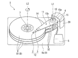
次に、本発明に係る軸受装置の実施形態を図1〜図9に基づいて説明する。なお、本実施形態では、軸受装置が情報記録再生装置のピボット軸に用いられている場合について説明する。 Next, an embodiment of a bearing device according to the present invention will be described with reference to FIGS. In the present embodiment, the case where the bearing device is used for the pivot shaft of the information recording / reproducing apparatus will be described.
図1は、本発明に係る情報記録再生装置1の概略構成図である。なお、本実施形態の情報記録再生装置1は、垂直記録層を有するディスク(磁気記録媒体)Dに対して、垂直記録方式で書き込みを行う装置である。 FIG. 1 is a schematic configuration diagram of an information recording / reproducing apparatus 1 according to the present invention. Note that the information recording / reproducing apparatus 1 of the present embodiment is an apparatus for writing on a disk (magnetic recording medium) D having a perpendicular recording layer by a perpendicular recording method.
図1に示すように、情報記録再生装置1は、キャリッジ11と、キャリッジ11の基端側から光導波路32を介して光束を供給するレーザ光源20と、キャリッジ11の先端側に支持されたヘッドジンバルアセンブリ(HGA)12と、ヘッドジンバルアセンブリ12をディスク面D1(ディスクDの表面)に平行な水平面内方向にスキャン移動させるアクチュエータ6と、ディスクDを回転軸L2を中心に回転させるスピンドルモータ7と、情報に応じて変調した電流をヘッドジンバルアセンブリ12のスライダ2に対して供給する制御部5と、これら各構成品を内部に収容するハウジング9と、を備えている。
As shown in FIG. 1, the information recording / reproducing apparatus 1 includes a
ハウジング9は、アルミニウム等の金属材料からなる上部開口部を有する箱型形状のものであり、上面視四角形状の底部9aと、底部9aの周縁において底部9aに対して鉛直方向に立設する周壁(不図示)とで構成されている。そして、周壁に囲まれた内側には、上述した各構成品を収容する凹部が形成される。なお、図1においては、説明を分かりやすくするため、ハウジング9の周囲を取り囲む周壁を省略している。
The
また、このハウジング9には、ハウジング9の開口を塞ぐように図示しない蓋が着脱可能に固定されるようになっている。底部9aの略中心には、上記スピンドルモータ7が取り付けられており、該スピンドルモータ7に中心孔を嵌め込むことでディスクDが着脱自在に固定されている。
Further, a lid (not shown) is detachably fixed to the
ディスクDの外側で、底部9aの一つの隅角部には、上述したアクチュエータ6が取り付けられている。このアクチュエータ6には、ピボット軸(軸受装置)10を中心に水平面内で回転軸L1を中心に回動可能なキャリッジ11が取り付けられている。このキャリッジ11は、基端部から先端部に向けて(ディスクD方向に向けて)延設されたアーム部14と、アーム部14を基端部を介して片持ち状に支持する基部15とが、削り出し加工等により一体形成されたものである。基部15は、略直方体形状に形成されたものであり、ピボット軸10まわりを回動可能に支持されている。つまり、基部15はピボット軸10を介してアクチュエータ6に連結されており、このピボット軸10がキャリッジ11の回転中心となっている。
The
アーム部14は、基部15におけるアクチュエータ6が取り付けられた側面15aと反対側の側面(隅角部の反対側の側面)15bにおいて、基部15の上面の面方向(水平面内方向)と平行に延出する平板状のものであり、基部15の高さ方向(垂直方向)に沿って3枚延出している。具体的には、アーム部14は、基端部から先端部に向かうにつれ先細るテーパ形状に形成されており、各アーム部14,14間に、ディスクDが挟み込まれるように配置されている。つまり、アーム部14とディスクDとが、交互に配置可能に構成されており、アクチュエータ6の駆動によってアーム部14がディスクDの表面に平行な方向(水平面内方向)に移動可能になっている。なお、キャリッジ11及びヘッドジンバルアセンブリ12は、ディスクDの回転停止時にアクチュエータ6の駆動によって、ディスクD上から退避するようになっている。
The
ヘッドジンバルアセンブリ12は、アーム部14の先端に連接されており、サスペンション3と、サスペンション3の先端に取り付けられたスライダ2とを備えている。また、ヘッドジンバルアセンブリ12は、図示しない近接場光発生素子を有するスライダ2に、レーザ光源20からの光束を導いて近接場光(スポット光)を発生させ、該近接場光を利用してディスクDに各種情報を記録再生させるものである。なお、近接場光発生素子は、例えば、光学的微小開口や、ナノメートルサイズに形成された突起部等により構成されている。
The
図2に示すように、ピボット軸10は、略円柱状に形成されたシャフト41と、シャフト41の外周面41aに対して所定間隔離間して配される略円筒状のスリーブ43と、シャフト41とスリーブ43との間に介装される第一転がり軸受51と、シャフト41とスリーブ43との間に、第一転がり軸受51と所定間隔離間して並列して介装される第二転がり軸受52と、を有している。
As shown in FIG. 2, the
シャフト41は、略円柱形状の棒状部材であり、長手方向(軸方向)の一端側に第一転がり軸受51が装着され、第一転がり軸受51と軸方向に所定間隔を空けて第二転がり軸受52が装着されている。また、シャフト41の一端側の端面には、シャフト41の直径よりも拡径され、第一転がり軸受51と当接されるフランジ部44が形成されている。さらに、シャフト41の外周面41aにおける第一転がり軸受51および第二転がり軸受52と当接する位置に接着剤Bを塗布する第一接着用溝部71および第二接着用溝部72がシャフト41の外周面41aの全周に亘ってそれぞれ形成されている。
The
スリーブ43は、略円筒形状に形成された部材であり、長手方向(軸方向)の一端側に第一転がり軸受51が装着され、他端側に第二転がり軸受52が装着される。また、スリーブ43における第一転がり軸受51と第二転がり軸受52とが配される間には、第一転がり軸受51と第二転がり軸受52との間隔を所定距離に保持するスペーサ部45が径方向内側に突出形成されている。さらに、スリーブ43の内周面43aにおける第一転がり軸受51および第二転がり軸受52と当接する位置に接着剤を塗布する第三接着用溝部73および第四接着用溝部74がスリーブ43の内周面43aの全周に亘ってそれぞれ形成されている。なお、スリーブ43とスペーサ部45とは別部材で構成してもよい。
The
第一転がり軸受51および第二転がり軸受52は、同一形状で形成された軸受である。具体的には、第一転がり軸受51は、内輪51aと、内輪51aに対して同軸に配置される外輪51bと、内輪51aと外輪51bとの間に介装され、所定位置で転動する複数の転動体51cとを有している。同様に、第二転がり軸受52は、内輪52aと、内輪52aに対して同軸に配置される外輪52bと、内輪52aと外輪52bとの間に介装され、所定位置で転動する複数の転動体52cとを有している。なお、転動体51c,52cは、それぞれの内輪と外輪との間で、図示しない保持器により保持されている。
The first rolling bearing 51 and the second rolling bearing 52 are bearings formed in the same shape. Specifically, the first rolling bearing 51 is interposed between the
また、第一転がり軸受51の内輪51aおよび外輪51bには、転動体51cを転動可能に保持する凹陥状の転走面51dが対向するように形成されている。同様に、第二転がり軸受52の内輪52aおよび外輪52bには、転動体52cを転動可能に保持する凹陥状の転走面52dが対向するように形成されている。
Further, the
ここで、第一接着用溝部71〜第四接着用溝部74は、転走面51d,52dと軸L1方向において重ならない位置に形成されている。また、第一接着用溝部71は転動体51c(転走面51dの軸L1方向における中央となる第一中央部51e)よりもフランジ部44側に形成され、第二接着用溝部72は転動体52c(転走面52dの軸L1方向における中央となる第二中央部52e)よりも第一転がり軸受51側に形成されている。一方、第三接着用溝部73は転動体51cよりも第二転がり軸受52側に形成され、第四接着用溝部74は転動体52cよりも第一転がり軸受51側に形成されている。なお、第一接着用溝部71〜第四接着用溝部74は軸L1に沿う方向の断面形状が略長方形に形成されている。
Here, the
次に、ピボット軸10の製造方法について図3〜図6を用いて説明する。
まず、図3に示すように、シャフト41の外周面41aに形成された第一接着用溝部71に接着剤Bを塗布する。なお、接着剤としては例えば熱硬化性の接着剤を使用する。そして、第一転がり軸受51にシャフト41を挿通して、第一転がり軸受51の内輪51aがフランジ部44に当接するまで押し込む。
Next, a method for manufacturing the
First, as shown in FIG. 3, the adhesive B is applied to the
次に、図4に示すように、スリーブ43の内周面43aに形成された第四接着用溝部74に接着剤Bを塗布する。スリーブ43に第二転がり軸受52を挿入して、第二転がり軸受52の外輪52bがスペーサ部45に当接するまで押し込む。
Next, as shown in FIG. 4, the adhesive B is applied to the
次に、図5に示すように、シャフト41の外周面41aに形成された第二接着用溝部72に接着剤Bを塗布するとともに、スリーブ43の内周面43aに形成された第三接着用溝部73に接着剤Bを塗布する。
そして、第二転がり軸受52が取り付けられた上記スリーブ43に、第一転がり軸受51が取り付けられた上記シャフト41を挿通して、第一転がり軸受51の外輪51bがスペーサ部45に当接するまで押し込む。
Next, as shown in FIG. 5, the adhesive B is applied to the
Then, the
そして、図6に示すように、第二転がり軸受52の内輪52aを第一転がり軸受51側に所定圧力で押圧しながら第一転がり軸受51および第二転がり軸受52をシャフト41およびスリーブ43に固定する。なお、第二転がり軸受52の内輪52aを所定圧力で押圧する際には押圧冶具75を用いる。この押圧冶具75は、先端が平坦面に形成されたものであり、押圧冶具75を第二転がり軸受52の内輪52aの端面に当接させることができる。
Then, as shown in FIG. 6, the first rolling bearing 51 and the second rolling bearing 52 are fixed to the
押圧冶具75を用いて第一転がり軸受51および第二転がり軸受52をシャフト41およびスリーブ43に固定した後に、恒温槽に入れて接着剤Bを熱硬化させることによりピボット軸10の製造が完了する。
After the first rolling bearing 51 and the second rolling bearing 52 are fixed to the
ここで、本実施形態では、第一接着用溝部71〜第四接着用溝部74を転走面51d,52dと軸L1方向において重ならない位置に形成している。つまり、第一接着用溝部71〜第四接着用溝部74に対向する位置の内輪51a,52aおよび外輪51b,52bの肉厚は厚いため、接着剤Bを熱硬化させる際に接着剤Bが膨張しても、転走面51d,52dはその影響を受けない。結果として、転走面51d,52dの歪みを抑制でき、トルク変動が大きくなるのを抑制することができる。
Here, in this embodiment, the
また、本実施形態によれば、第一接着用溝部71は転動体51cよりもフランジ部44側に形成し、第二接着用溝部72は転動体52cよりも第一転がり軸受51側に形成した。一方、第三接着用溝部73は転動体51cよりも第二転がり軸受52側に形成し、第四接着用溝部74は転動体52cよりも第一転がり軸受51側に形成した。
Further, according to the present embodiment, the
このように第一接着用溝部71〜第四接着用溝部74を形成することで、第一転がり軸受51および第二転がり軸受52をシャフト41およびスリーブ43に取り付ける際に、接着剤Bが塗布された第一接着用溝部71〜第四接着用溝部74と第一転がり軸受51および第二転がり軸受52の内輪51a,52aの内周面または外輪51b,52bの外周面とが重なり合う長さ(擦れ合う長さ)を最小限に抑えることができる。つまり、接着剤Bが第一接着用溝部71〜第四接着用溝部74以外の転がり軸受51,52とシャフト41およびスリーブ43との隙間にひきずられて転走面51d,52dの中央部51e,52eに付着するのを抑制することができる。したがって、このような状態で接着剤Bを熱硬化させても、転がり軸受51,52の真円度が悪化することなく、転走面51d,52dの歪みを抑制することが可能になり、トルク変動が大きくなるのを抑制することができる。
By forming the
そして、本実施形態に係る情報記録再生装置1は、接着剤Bのひきずりを抑制し、トルク変動が大きくなることを抑制することができるピボット軸10を備えているため、ディスクDに対してヘッドジンバルアセンブリ12を高精度に位置制御をすることができる。
The information recording / reproducing apparatus 1 according to the present embodiment includes the
次に、ピボット軸10の別の製造方法について図7〜図9を用いて説明する。
まず、図7に示すように、スリーブ43の内周面43aに形成された第三接着用溝部73に接着剤Bを塗布する。スリーブ43に第一転がり軸受51を挿入して、第一転がり軸受51の外輪51bがスペーサ部45に当接するまで押し込む。
次に、図8に示すように、シャフト41の外周面41aに形成された第一接着用溝部71に接着剤Bを塗布する。そして、第一転がり軸受51が取り付けられたスリーブ43にシャフト41を挿通して、第一転がり軸受51の内輪51aがフランジ部44に当接するまで押し込む。
Next, another method for manufacturing the
First, as shown in FIG. 7, the adhesive B is applied to the
Next, as shown in FIG. 8, the adhesive B is applied to the
次に、図9に示すように、シャフト41の外周面41aに形成された第二接着用溝部72およびスリーブ43の内周面43aに形成された第四接着用溝部74に接着剤Bを塗布する。シャフト41とスリーブ43との間に第二転がり軸受52を挿入して、第二転がり軸受52の外輪52bがスペーサ部45に当接するまで押し込む。
Next, as shown in FIG. 9, the adhesive B is applied to the
そして、上記図6と同様に、第二転がり軸受52の内輪52aを第一転がり軸受51側に所定圧力で押圧しながら第一転がり軸受51および第二転がり軸受52をシャフト41およびスリーブ43に固定する。
6, the first rolling bearing 51 and the second rolling bearing 52 are fixed to the
押圧冶具75を用いて第一転がり軸受51および第二転がり軸受52をシャフト41およびスリーブ43に固定した後に、恒温槽に入れて接着剤Bを熱硬化させることによりピボット軸10の製造が完了する。このような製造手順でピボット軸10を製造しても、上述と同様に接着剤Bのひきずりを抑制することができる。
After the first rolling bearing 51 and the second rolling bearing 52 are fixed to the
尚、本発明は、上述した実施形態に限定されるものではなく、本発明の趣旨を逸脱しない範囲において、上述した実施形態に種々の変更を加えたものを含む。すなわち、実施形態で挙げた具体的な形状や構成等は一例にすぎず、適宜変更が可能である。
例えば、本実施形態では、軸受装置を近接場光ヘッドを有する情報記録再生装置のピボット軸に採用した場合の説明をしたが、これに限らず、一般的なHDDや光ディスク装置などの軸受装置や各種装置の回転軸部に採用することができる。
Note that the present invention is not limited to the above-described embodiment, and includes various modifications made to the above-described embodiment without departing from the spirit of the present invention. That is, the specific shapes, configurations, and the like given in the embodiment are merely examples, and can be changed as appropriate.
For example, in the present embodiment, the case where the bearing device is adopted as the pivot shaft of the information recording / reproducing device having the near-field optical head has been described. It can be employed in the rotating shaft portion of various devices.
また、本実施形態では、接着用溝部を転走面と重ならない位置に形成したが、少なくとも転走面の軸方向における中央部を避けた位置に形成することにより、従来のものより転走面の歪みを抑制することができる。 Further, in this embodiment, the bonding groove is formed at a position that does not overlap the rolling surface, but at least at the position avoiding the central portion in the axial direction of the rolling surface, the rolling surface is more than conventional. Can be suppressed.
さらに、本実施形態では、接着用溝部の形状を断面長方形の場合で説明したが、図10に示すように、転走面の軸方向における中央部に向かって徐々に浅くなる断面三角形に形成してもよい。
このように構成することで、接着用溝部の加工が容易になり生産効率を向上することができる。また、転走面の軸方向における中央部に向かって徐々に浅くなる断面三角形に形成することにより、内輪および外輪の肉厚の薄い転走面に対向する位置に塗布する接着剤の量を少なくすることができる。したがって、転走面に対向する位置近傍の接着剤の膨張量を小さくすることができるため、転走面の歪みを抑制でき、トルク変動が大きくなるのを抑制することができる。なお、接着用溝部の断面形状は三角形でなくてもよく、端部から中央部に向かって徐々に浅くなるように形成すれば略同一の効果が得られる。
Furthermore, in the present embodiment, the shape of the bonding groove has been described in the case of a rectangular cross section, but as shown in FIG. 10, it is formed in a cross sectional triangle that gradually becomes shallower toward the central portion in the axial direction of the rolling surface. May be.
By comprising in this way, the process of the groove part for adhesion | attachment becomes easy and it can improve production efficiency. Also, by forming a cross-sectional triangle that gradually decreases toward the center in the axial direction of the rolling surface, the amount of adhesive applied to the position facing the thin rolling surface of the inner ring and outer ring is reduced. can do. Therefore, since the expansion amount of the adhesive in the vicinity of the position facing the rolling surface can be reduced, distortion of the rolling surface can be suppressed, and increase in torque fluctuation can be suppressed. Note that the cross-sectional shape of the bonding groove portion does not have to be triangular, and substantially the same effect can be obtained if it is formed so as to gradually become shallower from the end portion toward the central portion.
そして、図11に示すように、接着用溝部は転がり軸受の軸方向の端部に対応する位置まで延設させて形成してもよい。
このように接着用溝部を形成することにより転がり軸受の端部にテーパが形成されている場合、接着剤溜まりの空間Sを大きく確保することができ、転がり軸受をシャフトおよびスリーブに強固に接着することが可能となる。
And as shown in FIG. 11, you may form the groove part for adhesion | attachment by extending to the position corresponding to the edge part of the axial direction of a rolling bearing.
When the end portion of the rolling bearing is tapered by forming the bonding groove in this way, a large space S for the adhesive pool can be secured, and the rolling bearing is firmly bonded to the shaft and the sleeve. It becomes possible.
1…情報記録再生装置 10…ピボット軸(軸受装置) 11…キャリッジ 12…ヘッドジンバルアセンブリ 14…アーム部 20…レーザ光源(光源) 41…シャフト 41a…周面 43…スリーブ 43a…内周面 44…フランジ部 45…スペーサ部 51…第一転がり軸受 51a…内輪 51b…外輪 51c…転動体 51d…転走面 51e…第一中央部 52…第二転がり軸受 52a…内輪 52b…外輪 52c…転動体 52d…転走面 52e…第二中央部 71…第一接着用溝部 72…第二接着用溝部 73…第三接着用溝部 74…第四接着用溝部 75…押圧冶具(冶具) B…接着剤 D…ディスク(磁気記録媒体)
DESCRIPTION OF SYMBOLS 1 ... Information recording / reproducing
Claims (2)
該シャフトの外周面に対して所定間隔離間して同軸状に配される円筒状のスリーブと、
前記シャフトと前記スリーブとの間に配置され、内輪が前記シャフトに接着固定されるとともに、外輪が前記スリーブに接着固定され、前記内輪が前記フランジ部に当接された第一転がり軸受と、
該第一転がり軸受から前記シャフトの軸方向に所定間隔離間した位置に配され、内輪が前記シャフトに接着固定されるとともに、外輪が前記スリーブに接着固定された第二転がり軸受と、を備え、
前記シャフトの外周面における前記第一転がり軸受との当接箇所に形成された第一接着用溝部と、
前記シャフトの外周面における前記第二転がり軸受との当接箇所に形成された第二接着用溝部と、
前記スリーブの内周面における前記第一転がり軸受との当接箇所に形成された第三接着用溝部と、
前記スリーブの内周面における前記第二転がり軸受との当接箇所に形成された第四接着用溝部と、
前記スリーブにおける前記第一転がり軸受と前記第二転がり軸受との間で、前記第一転がり軸受と前記第二転がり軸受との間隔を所定距離に保持するスペーサ部が、前記スリーブの周方向に当接されるとともに、前記スリーブの径方向内側に向かって突出配置された軸受装置の製造方法において、
前記第一接着用溝部が、前記第一転がり軸受の前記内輪と前記外輪との間に介装される転動体を配置するために前記内輪および前記外輪に形成された転走面の軸方向における第一中央部よりも前記フランジ側に形成され、
前記第二接着用溝部が、前記第二転がり軸受の前記内輪と前記外輪との間に介装される転動体を配置するために前記内輪および前記外輪に形成された転走面の軸方向における第二中央部よりも前記フランジ側に形成され、
前記第三接着用溝部が、前記第一中央部よりも前記スペーサ側に形成され、
前記第四接着用溝部が、前記第二中央部よりも前記スペーサ側に形成されており、
前記第一接着用溝部に接着剤を塗布する工程と、
前記第一転がり軸受に前記シャフトを挿通して、前記フランジ部と前記第一転がり軸受の内輪とを当接させる工程と、
前記第四接着用溝部に接着剤を塗布する工程と、
前記スリーブに前記第二転がり軸受を挿入して、前記スペーサ部と前記第二転がり軸受の外輪とを当接させる工程と、
前記第二接着用溝部および第三接着用溝部に接着剤を塗布する工程と、
前記第二転がり軸受が取り付けられた前記スリーブに前記第一転がり軸受が取り付けられた前記シャフトを挿通して、前記スペーサ部と前記第一転がり軸受の外輪とを当接させる工程と、を有していることを特徴とする軸受装置の製造方法。 A shaft having a flange portion formed in a cylindrical shape and having a diameter expanded at one end portion in the axial direction;
A cylindrical sleeve disposed coaxially with a predetermined interval from the outer peripheral surface of the shaft;
A first rolling bearing disposed between the shaft and the sleeve, wherein an inner ring is bonded and fixed to the shaft, an outer ring is bonded and fixed to the sleeve, and the inner ring is in contact with the flange portion;
A second rolling bearing disposed at a position spaced apart from the first rolling bearing in the axial direction of the shaft by a predetermined interval, an inner ring being bonded and fixed to the shaft, and an outer ring being bonded and fixed to the sleeve;
A first adhering groove formed in a contact portion with the first rolling bearing on the outer peripheral surface of the shaft;
A second bonding groove formed at a contact point with the second rolling bearing on the outer peripheral surface of the shaft;
A third bonding groove formed in a contact portion with the first rolling bearing on the inner peripheral surface of the sleeve;
A fourth bonding groove formed at a contact portion with the second rolling bearing on the inner peripheral surface of the sleeve;
Between the first rolling bearing and the second rolling bearing in the sleeve, a spacer portion that holds a distance between the first rolling bearing and the second rolling bearing at a predetermined distance is applied in the circumferential direction of the sleeve. In the manufacturing method of the bearing device that is in contact with and arranged to protrude radially inward of the sleeve,
In the axial direction of the rolling surface formed on the inner ring and the outer ring, the first bonding groove portion is provided with a rolling element interposed between the inner ring and the outer ring of the first rolling bearing. Formed on the flange side from the first central portion,
In the axial direction of the rolling surface formed on the inner ring and the outer ring, the second bonding groove portion is disposed between the inner ring and the outer ring of the second rolling bearing. Formed on the flange side from the second central portion,
The third bonding groove is formed closer to the spacer than the first central portion;
The fourth bonding groove is formed closer to the spacer than the second central portion;
Applying an adhesive to the first bonding groove;
Inserting the shaft through the first rolling bearing to bring the flange portion into contact with the inner ring of the first rolling bearing;
Applying an adhesive to the fourth bonding groove;
Inserting the second rolling bearing into the sleeve and bringing the spacer portion into contact with the outer ring of the second rolling bearing;
Applying an adhesive to the second bonding groove and the third bonding groove;
Inserting the shaft on which the first rolling bearing is attached to the sleeve to which the second rolling bearing is attached, and abutting the spacer portion with the outer ring of the first rolling bearing. A method for manufacturing a bearing device.
該シャフトの外周面に対して所定間隔離間して同軸状に配される円筒状のスリーブと、
前記シャフトと前記スリーブとの間に配置され、内輪が前記シャフトに接着固定されるとともに、外輪が前記スリーブに接着固定され、前記内輪が前記フランジ部に当接された第一転がり軸受と、
該第一転がり軸受から前記シャフトの軸方向に所定間隔離間した位置に配され、内輪が前記シャフトに接着固定されるとともに、外輪が前記スリーブに接着固定された第二転がり軸受と、を備え、
前記シャフトの外周面における前記第一転がり軸受との当接箇所に形成された第一接着用溝部と、
前記シャフトの外周面における前記第二転がり軸受との当接箇所に形成された第二接着用溝部と、
前記スリーブの内周面における前記第一転がり軸受との当接箇所に形成された第三接着用溝部と、
前記スリーブの内周面における前記第二転がり軸受との当接箇所に形成された第四接着用溝部と、
前記スリーブにおける前記第一転がり軸受と前記第二転がり軸受との間で、前記第一転がり軸受と前記第二転がり軸受との間隔を所定距離に保持するスペーサ部が、前記スリーブの周方向に当接されるとともに、前記スリーブの径方向内側に向かって突出配置された軸受装置の製造方法において、
前記第一接着用溝部が、前記第一転がり軸受の前記内輪と前記外輪との間に介装される転動体を配置するために前記内輪および前記外輪に形成された転走面の軸方向における第一中央部よりも前記フランジ側に形成され、
前記第二接着用溝部が、前記第二転がり軸受の前記内輪と前記外輪との間に介装される転動体を配置するために前記内輪および前記外輪に形成された転走面の軸方向における第二中央部よりも前記フランジ側に形成され、
前記第三接着用溝部が、前記第一中央部よりも前記スペーサ側に形成され、
前記第四接着用溝部が、前記第二中央部よりも前記スペーサ側に形成されており、
前記第三接着用溝部に接着剤を塗布する工程と、
前記スリーブに前記第一転がり軸受を挿入して、前記スペーサ部と前記第一転がり軸受の外輪とを当接させる工程と、
前記第一接着用溝部に接着剤を塗布する工程と、
前記第一転がり軸受が取り付けられた前記スリーブに前記シャフトを挿通して、前記フランジ部と前記第一転がり軸受の内輪とを当接させる工程と、
前記第二接着用溝部および前記第四接着用溝部に接着剤を塗布する工程と、
前記第二転がり軸受を前記シャフトに挿通させ、前記スペーサ部と前記第二転がり軸受の外輪とを当接させる工程と、を有していることを特徴とする軸受装置の製造方法。 A shaft having a flange portion formed in a cylindrical shape and having a diameter expanded at one end portion in the axial direction;
A cylindrical sleeve disposed coaxially with a predetermined interval from the outer peripheral surface of the shaft;
A first rolling bearing disposed between the shaft and the sleeve, wherein an inner ring is bonded and fixed to the shaft, an outer ring is bonded and fixed to the sleeve, and the inner ring is in contact with the flange portion;
A second rolling bearing disposed at a position spaced apart from the first rolling bearing in the axial direction of the shaft by a predetermined interval, an inner ring being bonded and fixed to the shaft, and an outer ring being bonded and fixed to the sleeve;
A first adhering groove formed in a contact portion with the first rolling bearing on the outer peripheral surface of the shaft;
A second bonding groove formed at a contact point with the second rolling bearing on the outer peripheral surface of the shaft;
A third bonding groove formed in a contact portion with the first rolling bearing on the inner peripheral surface of the sleeve;
A fourth bonding groove formed at a contact portion with the second rolling bearing on the inner peripheral surface of the sleeve;
Between the first rolling bearing and the second rolling bearing in the sleeve, a spacer portion that holds a distance between the first rolling bearing and the second rolling bearing at a predetermined distance is applied in the circumferential direction of the sleeve. In the manufacturing method of the bearing device that is in contact with and arranged to protrude radially inward of the sleeve,
In the axial direction of the rolling surface formed on the inner ring and the outer ring, the first bonding groove portion is provided with a rolling element interposed between the inner ring and the outer ring of the first rolling bearing. Formed on the flange side from the first central portion,
In the axial direction of the rolling surface formed on the inner ring and the outer ring, the second bonding groove portion is disposed between the inner ring and the outer ring of the second rolling bearing. Formed on the flange side from the second central portion,
The third bonding groove is formed closer to the spacer than the first central portion;
The fourth bonding groove is formed closer to the spacer than the second central portion;
Applying an adhesive to the third bonding groove;
Inserting the first rolling bearing into the sleeve and bringing the spacer portion into contact with the outer ring of the first rolling bearing;
Applying an adhesive to the first bonding groove;
Inserting the shaft through the sleeve to which the first rolling bearing is attached and bringing the flange portion into contact with the inner ring of the first rolling bearing;
Applying an adhesive to the second bonding groove and the fourth bonding groove;
And a step of inserting the second rolling bearing into the shaft and bringing the spacer portion into contact with the outer ring of the second rolling bearing .
Priority Applications (1)
| Application Number | Priority Date | Filing Date | Title |
|---|---|---|---|
| JP2008222505A JP5288545B2 (en) | 2008-08-29 | 2008-08-29 | Manufacturing method of bearing device |
Applications Claiming Priority (1)
| Application Number | Priority Date | Filing Date | Title |
|---|---|---|---|
| JP2008222505A JP5288545B2 (en) | 2008-08-29 | 2008-08-29 | Manufacturing method of bearing device |
Publications (2)
| Publication Number | Publication Date |
|---|---|
| JP2010054030A JP2010054030A (en) | 2010-03-11 |
| JP5288545B2 true JP5288545B2 (en) | 2013-09-11 |
Family
ID=42070168
Family Applications (1)
| Application Number | Title | Priority Date | Filing Date |
|---|---|---|---|
| JP2008222505A Active JP5288545B2 (en) | 2008-08-29 | 2008-08-29 | Manufacturing method of bearing device |
Country Status (1)
| Country | Link |
|---|---|
| JP (1) | JP5288545B2 (en) |
Families Citing this family (5)
| Publication number | Priority date | Publication date | Assignee | Title |
|---|---|---|---|---|
| JP2011256989A (en) * | 2010-06-11 | 2011-12-22 | Seiko Instruments (Thailand) Ltd | Bearing device and information recording/reproducing device |
| JP5746905B2 (en) * | 2011-04-28 | 2015-07-08 | ミネベア株式会社 | Pivot assembly bearing |
| JP6304795B2 (en) * | 2012-10-15 | 2018-04-04 | セイコーインスツル株式会社 | Manufacturing method of bearing device |
| JP5380598B1 (en) * | 2012-11-22 | 2014-01-08 | ミネベア株式会社 | Pivot assembly bearing device |
| NL2019379B1 (en) * | 2017-07-31 | 2019-02-19 | Vostermans Ventilation B V | Method for realizing a bearing for bearing a rotatable shaft in a bearing receiving space and bearing obtainable by the method |
Family Cites Families (4)
| Publication number | Priority date | Publication date | Assignee | Title |
|---|---|---|---|---|
| JP3255945B2 (en) * | 1991-10-01 | 2002-02-12 | 日本電産株式会社 | Spindle motor |
| JPH08184322A (en) * | 1994-12-28 | 1996-07-16 | Ntn Corp | Structure of bondedly fixed part of bearing and its fixing method |
| JPH11182543A (en) * | 1997-12-19 | 1999-07-06 | Nippon Seiko Kk | Double row rolling bearing unit and manufacture thereof |
| JP2005276291A (en) * | 2004-03-24 | 2005-10-06 | Hitachi Global Storage Technologies Netherlands Bv | Rotary disk-shaped storage device and pivot bearing assembly |
-
2008
- 2008-08-29 JP JP2008222505A patent/JP5288545B2/en active Active
Also Published As
| Publication number | Publication date |
|---|---|
| JP2010054030A (en) | 2010-03-11 |
Similar Documents
| Publication | Publication Date | Title |
|---|---|---|
| JP5288545B2 (en) | Manufacturing method of bearing device | |
| KR20030009086A (en) | Rotor assembly, information-recording/-reproducing device using the rotor assembly and method of assembling the rotor assembly | |
| JP2009150505A (en) | Bearing mechanism, motor and storage disk drive device | |
| JP5181343B2 (en) | Bearing device and information recording / reproducing device | |
| JP5181342B2 (en) | Bearing device, bearing device manufacturing method, and information recording / reproducing device | |
| US9091299B2 (en) | Bearing device, method of manufacturing bearing device, and information recording/reproducing apparatus | |
| JP2013054810A (en) | Bearing device and information recording and reproducing device | |
| JP2013174339A (en) | Rolling bearing, bearing device, information record reproducing device and method of manufacturing rolling bearing | |
| JP2014070701A (en) | Bearing device, manufacturing method of bearing device, and information recording and reproducing device | |
| WO2011111550A1 (en) | Torque measurement method for rolling bearing device, torque measurement device for rolling bearing device, torque measurement method for rolling bearing and torque measurement device for rolling bearing | |
| US9934799B2 (en) | Preloaded roller bearing device, information recording and reproducing device, and manufacturing method for bearing device | |
| JP6209374B2 (en) | Bearing device, bearing device manufacturing method, and information recording / reproducing device | |
| JPH10262355A (en) | Manufacture of spindle motor for disk storage | |
| US8786981B2 (en) | Bearing device, method of manufacturing bearing device, and information recording/reproducing apparatus | |
| JP5486826B2 (en) | Bearing device and information recording / reproducing device | |
| JP6529211B2 (en) | Bearing device, manufacturing method of bearing device, and information recording and reproducing apparatus | |
| JP5580664B2 (en) | Rolling bearing, bearing device, information recording / reproducing device | |
| JP2013181604A (en) | Rolling bearing, bearing device, and information recording/reproducing device | |
| JP6230421B2 (en) | Bearing device and information recording / reproducing device | |
| JP5677014B2 (en) | Rolling bearing, bearing device, information recording / reproducing device | |
| JP6210623B2 (en) | Bearing device, bearing device manufacturing method, and information recording / reproducing device | |
| JP2012189182A (en) | Rolling bearing, bearing device, and information recording/reproducing device | |
| JP6493935B2 (en) | Manufacturing method of bearing device | |
| JP2011204317A (en) | Rolling bearing device and pivot device | |
| JP2011256989A (en) | Bearing device and information recording/reproducing device |
Legal Events
| Date | Code | Title | Description |
|---|---|---|---|
| A711 | Notification of change in applicant |
Free format text: JAPANESE INTERMEDIATE CODE: A712 Effective date: 20100910 |
|
| A621 | Written request for application examination |
Free format text: JAPANESE INTERMEDIATE CODE: A621 Effective date: 20110610 |
|
| A977 | Report on retrieval |
Free format text: JAPANESE INTERMEDIATE CODE: A971007 Effective date: 20120530 |
|
| A131 | Notification of reasons for refusal |
Free format text: JAPANESE INTERMEDIATE CODE: A131 Effective date: 20120612 |
|
| A521 | Request for written amendment filed |
Free format text: JAPANESE INTERMEDIATE CODE: A523 Effective date: 20120802 |
|
| A131 | Notification of reasons for refusal |
Free format text: JAPANESE INTERMEDIATE CODE: A131 Effective date: 20121113 |
|
| A521 | Request for written amendment filed |
Free format text: JAPANESE INTERMEDIATE CODE: A523 Effective date: 20121227 |
|
| TRDD | Decision of grant or rejection written | ||
| A01 | Written decision to grant a patent or to grant a registration (utility model) |
Free format text: JAPANESE INTERMEDIATE CODE: A01 Effective date: 20130514 |
|
| RD03 | Notification of appointment of power of attorney |
Free format text: JAPANESE INTERMEDIATE CODE: A7423 Effective date: 20130531 |
|
| A61 | First payment of annual fees (during grant procedure) |
Free format text: JAPANESE INTERMEDIATE CODE: A61 Effective date: 20130531 |
|
| R150 | Certificate of patent or registration of utility model |
Ref document number: 5288545 Country of ref document: JP Free format text: JAPANESE INTERMEDIATE CODE: R150 |
|
| R250 | Receipt of annual fees |
Free format text: JAPANESE INTERMEDIATE CODE: R250 |
|
| R250 | Receipt of annual fees |
Free format text: JAPANESE INTERMEDIATE CODE: R250 |
|
| R250 | Receipt of annual fees |
Free format text: JAPANESE INTERMEDIATE CODE: R250 |
|
| R250 | Receipt of annual fees |
Free format text: JAPANESE INTERMEDIATE CODE: R250 |
|
| R250 | Receipt of annual fees |
Free format text: JAPANESE INTERMEDIATE CODE: R250 |
|
| R250 | Receipt of annual fees |
Free format text: JAPANESE INTERMEDIATE CODE: R250 |