JP5287828B2 - Head-up display device - Google Patents
Head-up display device Download PDFInfo
- Publication number
- JP5287828B2 JP5287828B2 JP2010239815A JP2010239815A JP5287828B2 JP 5287828 B2 JP5287828 B2 JP 5287828B2 JP 2010239815 A JP2010239815 A JP 2010239815A JP 2010239815 A JP2010239815 A JP 2010239815A JP 5287828 B2 JP5287828 B2 JP 5287828B2
- Authority
- JP
- Japan
- Prior art keywords
- axis direction
- liquid crystal
- concave
- image
- crystal display
- Prior art date
- Legal status (The legal status is an assumption and is not a legal conclusion. Google has not performed a legal analysis and makes no representation as to the accuracy of the status listed.)
- Expired - Fee Related
Links
Images


Classifications
-
- G—PHYSICS
- G02—OPTICS
- G02B—OPTICAL ELEMENTS, SYSTEMS OR APPARATUS
- G02B27/00—Optical systems or apparatus not provided for by any of the groups G02B1/00 - G02B26/00, G02B30/00
- G02B27/01—Head-up displays
-
- G—PHYSICS
- G02—OPTICS
- G02B—OPTICAL ELEMENTS, SYSTEMS OR APPARATUS
- G02B27/00—Optical systems or apparatus not provided for by any of the groups G02B1/00 - G02B26/00, G02B30/00
- G02B27/01—Head-up displays
- G02B27/0101—Head-up displays characterised by optical features
-
- G—PHYSICS
- G02—OPTICS
- G02B—OPTICAL ELEMENTS, SYSTEMS OR APPARATUS
- G02B27/00—Optical systems or apparatus not provided for by any of the groups G02B1/00 - G02B26/00, G02B30/00
- G02B27/01—Head-up displays
- G02B27/0101—Head-up displays characterised by optical features
- G02B2027/0118—Head-up displays characterised by optical features comprising devices for improving the contrast of the display / brillance control visibility
Landscapes
- Physics & Mathematics (AREA)
- General Physics & Mathematics (AREA)
- Optics & Photonics (AREA)
- Instrument Panels (AREA)
Description
本発明は、ウィンドシールド等の表示部材に表示像を投影するヘッドアップディスプレイ装置に関するものである。 The present invention relates to a head-up display device that projects a display image on a display member such as a windshield.
従来、ヘッドアップディスプレイ装置において、ウィンドシールド等の表示部材に投影される表示像の輝度のむらを低減する技術が知られている。例えば特許文献1に開示の照明装置は、表示像の基となる基画像を形成する液晶表示素子と、液晶表示素子に向けて光を放射する発光ダイオードと、表示部に表示像を投影するための凹面鏡とを備えている。この特許文献1には、凹面鏡と液晶表示素子との間に凹レンズを設けることにより、表示像の輝度のむらを低減しつつ、基画像に対する表示像の拡大比率を高めることができる旨の記載がある(特許文献1 段落0037参照)。 2. Description of the Related Art Conventionally, in a head-up display device, a technique for reducing unevenness in luminance of a display image projected on a display member such as a windshield is known. For example, the illumination device disclosed in Patent Document 1 projects a display image on a liquid crystal display element that forms a base image serving as a base of a display image, a light emitting diode that emits light toward the liquid crystal display element, and a display unit. And a concave mirror. Japanese Patent Laid-Open No. 2004-228688 describes that by providing a concave lens between a concave mirror and a liquid crystal display element, it is possible to increase the magnification ratio of the display image with respect to the base image while reducing unevenness in luminance of the display image. (See Patent Document 1, paragraph 0037).
この液晶表示素子と凹面鏡との間に設けられる凹レンズの作用について以下に説明する。液晶表示素子から出射される光の強度は、発光ダイオードから凹面鏡に向かう光軸に対する角度が大きくなるにつれて、低下する。故に、光軸に沿って液晶表示素子を透過した光を凹レンズの作用によって拡散させることにより、表示部材に投影される表示像の中央部分の輝度が抑制される。一方、表示像の外周部分の輝度は高められる。以上により、輝度むらの低減された表示像の投影が可能になる。 The operation of the concave lens provided between the liquid crystal display element and the concave mirror will be described below. The intensity of light emitted from the liquid crystal display element decreases as the angle with respect to the optical axis from the light emitting diode toward the concave mirror increases. Therefore, the light at the central portion of the display image projected on the display member is suppressed by diffusing the light transmitted through the liquid crystal display element along the optical axis by the action of the concave lens. On the other hand, the brightness of the outer peripheral portion of the display image is increased. As described above, it is possible to project a display image with reduced luminance unevenness.
さて、凹面鏡と液晶表示素子との間に、凹面鏡と凹レンズの凹曲面とが対向するように当該凹レンズを位置させた場合、以下に説明するような問題が発生することが判明した。その問題とは、表示像への外乱光の映り込みである。詳しく説明すると、特定の方向から入射した外乱光は、凹面鏡によって反射され、当該凹面鏡と対向する凹レンズの凹曲面に到達する。凹曲面に入射した外乱光は、発光ダイオードから凹面鏡に向かう光軸に対して垂直に位置している凹曲面の領域によって、凹面鏡に向けて反射される。するとこの外乱光は、液晶表示素子を透過した基画像の光像と共に表示部に投影され、表示像に映り込んでしまうのである。 When the concave lens is positioned between the concave mirror and the liquid crystal display element so that the concave mirror and the concave curved surface of the concave lens face each other, it has been found that the problem described below occurs. The problem is the reflection of ambient light on the display image. More specifically, disturbance light incident from a specific direction is reflected by the concave mirror and reaches the concave curved surface of the concave lens facing the concave mirror. The disturbance light incident on the concave curved surface is reflected toward the concave mirror by the concave curved region located perpendicular to the optical axis from the light emitting diode toward the concave mirror. Then, the disturbance light is projected onto the display unit together with the light image of the base image transmitted through the liquid crystal display element, and is reflected on the display image.
本願発明は、上記問題点に鑑みてなされたものであって、その目的は、輝度のむらの低減と、外乱光の映り込みの抑制とが実現された表示像を投影することができるヘッドアップディスプレイ装置を提供することである。 The present invention has been made in view of the above problems, and its purpose is a head-up display capable of projecting a display image in which reduction in luminance unevenness and suppression of disturbance light reflection are realized. Is to provide a device.
上記目的を達成するために、請求項1に記載の発明は、車両に搭載され、車両の鉛直方向よりも水平方向に長い横長の表示像を表示部材に投影するヘッドアップディスプレイ装置であって、表示像の基となる基画像を形成する液晶表示部と、液晶表示部の背面側から当該液晶表示部に向けて光を放射する光源部と、液晶表示部を通過した基画像の光像を反射することにより、表示部材に表示像を投影する反射鏡部と、車両の水平方向に沿ってx軸方向を規定した三次元の座標が設定され、y軸方向に沿い且つx軸方向おいて凹状に湾曲し反射鏡部と対向する凹曲面を有し、x軸周りに回転させることにより、光源部から反射鏡部に向かう光軸に対してz軸を傾斜させた姿勢にて、液晶表示部と反射鏡部との間に位置する凹シリンドリカルレンズと、を備えるヘッドアップディスプレイ装置とする。 To achieve the above object, an invention according to claim 1 is mounted on a vehicle, a head-up display apparatus for projecting a shadow on the display member horizontally long display image in the horizontal direction than the vertical direction of the vehicle A liquid crystal display unit that forms a base image as a basis of the display image, a light source unit that emits light from the back side of the liquid crystal display unit toward the liquid crystal display unit, and an optical image of the base image that has passed through the liquid crystal display unit Is reflected, and a reflecting mirror portion for projecting a display image on the display member, and three-dimensional coordinates defining the x-axis direction along the horizontal direction of the vehicle are set, along the y-axis direction and along the x-axis direction. The liquid crystal has a concave curved surface that has a concave curved surface facing the reflecting mirror part, and is rotated around the x axis so that the z axis is inclined with respect to the optical axis from the light source part toward the reflecting mirror part. Concave cylindrical carlen located between display and reflector When, the head-up display device comprising a.
この発明によれば、凹シリンドリカルレンズは、設定された三次元の座標においてx軸周りに回転されることにより、光源部から反射鏡部に向かう光軸に対してz軸を傾斜させた姿勢にて、液晶表示部と反射鏡部との間に位置している。加えて、この凹シリンドリカルレンズの凹曲面は、x軸方向においては凹状に湾曲しているものの、y軸方向に沿っている。故に、光軸に対するz軸方向の傾斜によって、光源部から反射鏡部に向かう光軸に対して垂直となる領域が、凹曲面から無くなり得る。以上により、反射鏡部にて反射された外乱光が凹シリンドリカルレンズの凹曲面に到達した場合であっても、この外乱光は、凹曲面にて反射鏡部とは異なる方向に向けて反射され得る。故に、凹曲面にて反射された外乱光が基画像の光像と共に表示部材に投影されてしまう事態は、抑制される。 According to the present invention, the concave cylindrical lens is rotated around the x axis in the set three-dimensional coordinates, so that the z axis is inclined with respect to the optical axis from the light source part toward the reflecting mirror part. And located between the liquid crystal display unit and the reflecting mirror unit. In addition, the concave curved surface of the concave cylindrical lens is curved in a concave shape in the x-axis direction, but is along the y-axis direction. Therefore, the region perpendicular to the optical axis from the light source unit toward the reflecting mirror unit may be eliminated from the concave curved surface due to the inclination in the z-axis direction with respect to the optical axis. As described above, even when the disturbance light reflected by the reflecting mirror portion reaches the concave curved surface of the concave cylindrical lens, the disturbance light is reflected toward the direction different from the reflecting mirror portion by the concave curved surface. obtain. Therefore, the situation where the disturbance light reflected by the concave curved surface is projected onto the display member together with the light image of the base image is suppressed.
加えて凹シリンドリカルレンズは、x軸方向において凹状に湾曲する凹曲面の作用によって、液晶表示部を透過した光を屈折により拡散させる。これにより、表示部材に投影される表示像においては、中央部分と外周部分との輝度差が低減される。したがって、ヘッドアップディスプレイ装置は、輝度のむらの低減と、外乱光の映り込みの抑制とが実現された表示像を投影することができる。
さらに、車両の水平方向に沿って凹シリンドリカルレンズのx軸方向を向けることにより、当該凹シリンドリカルレンズを通過した基画像の光像は、水平方向に拡散するように屈折される。これにより表示像においては、水平方向の輝度のむらが低減される。鉛直方向よりも水平方向に長い横長の表示像を表示部材に投影する形態では、当該水平方向の輝度のむらが顕著になり易い。故に、横長の表示像を投影する形態のヘッドアップディスプレイ装置では、凹シリンドリカルレンズのx軸方向を車両の水平方向に沿わせることが好適なのである。
In addition, the concave cylindrical lens diffuses light transmitted through the liquid crystal display unit by refraction by the action of a concave curved surface that is curved in a concave shape in the x-axis direction. Thereby, in the display image projected on the display member, the luminance difference between the central portion and the outer peripheral portion is reduced. Therefore, the head-up display device can project a display image in which reduction in luminance unevenness and suppression of disturbance light reflection are realized .
Furthermore, by directing the x-axis direction of the concave cylindrical lens along the horizontal direction of the vehicle, the light image of the base image that has passed through the concave cylindrical lens is refracted so as to diffuse in the horizontal direction. Thereby, in the display image, uneven brightness in the horizontal direction is reduced. In a mode in which a horizontally long display image that is longer in the horizontal direction than in the vertical direction is projected onto the display member, the uneven luminance in the horizontal direction is likely to be noticeable. Therefore, in a head-up display device that projects a horizontally long display image, it is preferable that the x-axis direction of the concave cylindrical lens be aligned with the horizontal direction of the vehicle.
請求項2に記載の発明では、基画像に対する表示像の拡大率が複数種類の中から設定されるヘッドアップディスプレイ装置であって、当該設定された拡大率に応じて凹曲面の曲率半径を規定された凹シリンドリカルレンズが液晶表示部と反射鏡部との間に位置し、光軸に対してx軸方向及びy軸方向に角度を持って出射される光のうち、光軸に沿う方向に出射される光に対して所定の強度比を維持している当該角度の範囲が、視野角として規定され、x軸方向における視野角は、複数種類の拡大率のうちで最も小さい拡大率が想定された場合にx軸方向において必要とされる視野角に合わせて規定され、y軸方向における視野角は、複数種類の拡大率のうちで最も大きい拡大率が想定された場合にy軸方向において必要とされる視野角に合わせて規定されることを特徴とする。 The invention according to claim 2 is a head-up display device in which an enlargement ratio of a display image with respect to a base image is set from a plurality of types, and a curvature radius of a concave curved surface is defined according to the set enlargement ratio The concave cylindrical lens is positioned between the liquid crystal display unit and the reflecting mirror unit, and in the direction along the optical axis of the light emitted with an angle in the x-axis direction and the y-axis direction with respect to the optical axis. The range of the angle maintaining a predetermined intensity ratio with respect to the emitted light is defined as the viewing angle, and the viewing angle in the x-axis direction is assumed to be the smallest among a plurality of types of magnifications. The viewing angle in the y-axis direction is defined in accordance with the viewing angle required in the x-axis direction, and the viewing angle in the y-axis direction is determined in the y-axis direction when the largest magnification rate among a plurality of types of magnification rates is assumed. According to the required viewing angle Characterized in that it is defined Te.
上述したように、光源部から放射され液晶表示部から出射される光の強度は、光軸に対する角度が大きくなるにつれて、低下する。故に、光軸に対して角度を持って出射される光のうち、光軸に沿う方向に出射される光に対して所定の強度比を維持している当該角度の範囲が視野角として規定されている。基画像に対する表示像の拡大率を大きくしようとすると、液晶表示部から反射鏡部までの距離が短くされると共に、必要とされる視野角も大きくなる。この発明では、拡大率は、複数種類の中から設定される。 As described above, the intensity of light emitted from the light source unit and emitted from the liquid crystal display unit decreases as the angle with respect to the optical axis increases. Therefore, the range of the angle maintaining a predetermined intensity ratio with respect to the light emitted in the direction along the optical axis among the light emitted with an angle with respect to the optical axis is defined as the viewing angle. ing. When the enlargement ratio of the display image with respect to the base image is increased, the distance from the liquid crystal display unit to the reflecting mirror unit is shortened and the required viewing angle is also increased. In the present invention, the enlargement ratio is set from a plurality of types.
まず、複数種類の拡大率のうちで最も大きい拡大率に設定された場合を説明する。液晶表示部及び光源部のx軸方向における視野角は、最も小さい拡大率が想定された場合にx軸方向において必要とされる視野角に合わせて規定されている。しかし、凹シリンドリカルレンズは、拡大率に応じて曲率半径を規定された凹曲面によって、x軸方向に拡散するよう光を屈折させることにより、視野角を拡大させる作用を発揮する。故に、凹シリンドリカルレンズを通過した後におけるx軸方向の視野角は、最も大きい拡大率が想定された場合にx軸方向において必要とされる視野角を満たしたものになり得る。 First, a case where the largest enlargement ratio among a plurality of kinds of enlargement ratios is set will be described. The viewing angle in the x-axis direction of the liquid crystal display unit and the light source unit is defined in accordance with the viewing angle required in the x-axis direction when the smallest enlargement ratio is assumed. However, the concave cylindrical lens exerts an effect of enlarging the viewing angle by refracting light so as to diffuse in the x-axis direction by a concave curved surface having a radius of curvature defined according to the magnification. Therefore, the viewing angle in the x-axis direction after passing through the concave cylindrical lens can satisfy the viewing angle required in the x-axis direction when the greatest magnification is assumed.
一方、液晶表示部及び光源部のy軸方向における視野角は、最も大きい拡大率が想定された場合においてy軸方向に必要とされる視野角に合わせて規定されている。故に、凹シリンドリカルレンズがy軸方向に光を拡散することできなくても、y軸方向に必要な視野角は、確保され得る。 On the other hand, the viewing angle in the y-axis direction of the liquid crystal display unit and the light source unit is defined in accordance with the viewing angle required in the y-axis direction when the largest enlargement ratio is assumed. Therefore, even if the concave cylindrical lens cannot diffuse light in the y-axis direction, a viewing angle required in the y-axis direction can be ensured.
次に、複数種類の拡大率のうちで最も小さい拡大率に設定された場合を説明する。液晶表示部及び光源部のx軸方向における視野角は、最も小さい拡大率が想定された場合においてx軸方向に必要とされる視野角に合わせて規定されている。故に、x軸方向において必要な視野角は確保され得る。一方、液晶表示部及び光源部のy軸方向における視野角は、上述したように最も大きい拡大率が想定された場合においてy軸方向に必要とされる視野角に合わせて規定されている。故に、y軸方向において必要な視野角は当然に確保され得る。 Next, the case where the smallest enlargement ratio among the plurality of kinds of enlargement ratios is set will be described. The viewing angle in the x-axis direction of the liquid crystal display unit and the light source unit is defined in accordance with the viewing angle required in the x-axis direction when the smallest enlargement ratio is assumed. Therefore, a necessary viewing angle in the x-axis direction can be ensured. On the other hand, the viewing angle in the y-axis direction of the liquid crystal display unit and the light source unit is defined in accordance with the viewing angle required in the y-axis direction when the largest enlargement ratio is assumed as described above. Therefore, a necessary viewing angle in the y-axis direction can be naturally secured.
以上のように、液晶表示部及び光源部を共有しても、複数種類の拡大率のそれぞれにおいて、ヘッドアップディスプレイ装置は、輝度むらの低減された表示像を表示することができる。したがって、輝度むらの低減及び外乱光の映り込み抑制を果たしたヘッドアップディスプレイ装置の安価な提供が実現できる。 As described above, even if the liquid crystal display unit and the light source unit are shared, the head-up display device can display a display image with reduced luminance unevenness at each of a plurality of types of magnifications. Therefore, it is possible to provide an inexpensive head-up display device that can reduce luminance unevenness and suppress reflection of ambient light.
請求項3に記載の発明では、車両に搭載され、表示部材として湾曲したウィンドシールドに表示像を投影するヘッドアップディスプレイ装置であって、反射鏡部は、ウィンドシールドの湾曲及び凹曲面の湾曲によって生じる表示像の歪みを補正するように形状を規定される反射面、を有することを特徴とする。 According to a third aspect of the present invention, there is provided a head-up display device that is mounted on a vehicle and projects a display image onto a curved windshield as a display member, and the reflecting mirror portion is formed by the curvature of the windshield and the curved curved surface. And a reflective surface whose shape is defined so as to correct the distortion of the display image.
一般に、車両のウィンドシールドには、車両毎に異なる湾曲が形成されている。故に、反射鏡部の有する反射面の形状は、ウィンドシールドにて生じる表示像の歪みが補正されるように、車両毎に規定されている。ここで、本発明では、液晶表示部を透過した基画像の光像は、凹シリンドリカルレンズの凹曲面によって屈折される。故に、凹曲面における屈折に起因した歪みが、基画像の光像には生じ得る。そこで、反射鏡部の有する反射面の形状を、ウィンドシールドの湾曲に起因した歪みと共に凹曲面の湾曲に起因した歪みも補正するように規定することにより、ヘッドアップディスプレイ装置の構成を複雑化することなく、表示像の歪みは補正され得る。以上により、ヘッドアップディスプレイ装置は、輝度むらの低減と外乱光の映り込みの抑制とが図られた歪みの無い表示像をウィンドシールドに投影することができる。 Generally, the vehicle windshield has a different curvature for each vehicle. Therefore, the shape of the reflecting surface of the reflecting mirror is defined for each vehicle so that the distortion of the display image generated by the windshield is corrected. Here, in the present invention, the light image of the base image transmitted through the liquid crystal display unit is refracted by the concave curved surface of the concave cylindrical lens. Therefore, distortion due to refraction on the concave curved surface can occur in the optical image of the base image. Therefore, the configuration of the head-up display device is complicated by defining the shape of the reflecting surface of the reflecting mirror unit so as to correct the distortion caused by the curvature of the concave curved surface as well as the distortion caused by the curvature of the windshield. Without being distorted, the distortion of the display image can be corrected. As described above, the head-up display device can project a distortion-free display image on the windshield in which luminance unevenness is reduced and disturbance light reflection is suppressed.
請求項4に記載の発明では、凹シリンドリカルレンズは、液晶表示部の表示面に当接し、当該液晶表示部を透過した基画像の光像を当該凹シリンドリカルレンズ内に入射させる、xy平面に沿う平坦な入射面、を有することを特徴とする。 In the invention according to claim 4 , the concave cylindrical lens is in contact with the display surface of the liquid crystal display unit, and enters the optical image of the base image transmitted through the liquid crystal display unit into the concave cylindrical lens along the xy plane. A flat incident surface.
この発明によれば、xy平面に沿って平坦な入射面を液晶表示部の表示面に当接させることにより、凹シリンドリカルレンズのx軸周り及びy軸周りの回転を抑制したうえで、液晶表示部に対する凹シリンドリカルレンズのxy平面方向の相対位置が調整され得る。これにより、液晶表示部に対する凹シリンドリカルレンズの位置決めが正確になされる。故に、液晶表示部に対する凹シリンドリカルレンズの相対位置のずれに起因する表示像の歪み及び輝度むらは、低減される。 According to the present invention, the flat incident surface is brought into contact with the display surface of the liquid crystal display unit along the xy plane, thereby suppressing the rotation of the concave cylindrical lens around the x axis and the y axis and the liquid crystal display. The relative position of the concave cylindrical lens in the xy plane direction with respect to the portion can be adjusted. Thereby, the concave cylindrical lens is accurately positioned with respect to the liquid crystal display unit. Therefore, display image distortion and luminance unevenness due to a shift in the relative position of the concave cylindrical lens with respect to the liquid crystal display unit are reduced.
以下、本発明の一実施形態を図面に基づいて説明する。 Hereinafter, an embodiment of the present invention will be described with reference to the drawings.
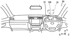
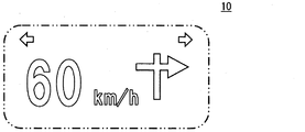
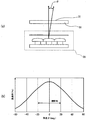
本発明の一実施形態によるヘッドアップディスプレイ装置100は、図1に示されるような車両のインスツルメントパネル91内に収容されている。ヘッドアップディスプレイ装置100は、例えば車両の湾曲したウィンドシールド90等の表示部材に、表示像10を投影する。表示像10は、図2に示されるように、車両の鉛直方向よりも水平方向に長い横長である。表示像10は、例えばヘッドアップディスプレイ装置100の搭載されている車両の走行速度、ナビゲーションシステムによる車両の進行方向の指示、方向指示器の作動を示すインジケータ、及び図示しない複数のウォーニング等を表示すことができる。表示像10は、図3に示されるように、ウィンドシールド90の前方にて結像され、虚像として運転者等の視認者に視認される。
A head-up
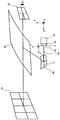
まず、ヘッドアップディスプレイ装置100の構成を、図3及び図4に基づいて説明する。ヘッドアップディスプレイ装置100は、液晶表示部30、標準光源20、及び凹面鏡40を備えている。
First, the configuration of the head-up
液晶表示部30は、ドットマトリクス方式の液晶表示パネルを有している。液晶表示部30は、液晶表示パネルに配列された複数の画素を制御することにより、カラー表示を行うことができる。液晶表示部30は、表示像10の基となる基画像11を液晶表示パネルによって形成する。液晶表示部30は、凹面鏡40と対向する平坦な表示面31を有している。液晶表示部30は、標準光源20によって背面側から透過照明される。
The liquid
標準光源20は、液晶表示部30の背面側に位置しており、液晶表示部30の背面側から当該液晶表示部30に向けて光を放射する。これにより標準光源20は、液晶表示部30を背面側から照明し、基画像11の光像を凹面鏡40に到達させる。標準光源20は、発光ダイオード21、インナーレンズ23、及び拡散板25を有している。発光ダイオード21は、電力の印加によって例えば白色光を放射する光源である。発光ダイオード21は、回路基板22に等間隔で配列されている。
The standard
インナーレンズ23は、アクリル樹脂又はポリカーボネート樹脂等の透光性の材料によって形成されている。インナーレンズ23には、入射面23a及び出射面23bが形成されている。入射面23aは、各発光ダイオード21から放射された光をインナーレンズ23内に入射させる。入射面23aは、回路基板22において各発光ダイオード21の実装されている実装面に沿う平面である。出射面23bは、液晶表示部30に向かって凸状に突出する凸曲面である。インナーレンズ23は、出射面23bによる屈折作用によって、当該出射面23bから出射される光を収束させる。
The
拡散板25は、アクリル樹脂又はポリカーボネート樹脂等の透光性の材料によって板状に形成されている。拡散板25の両表面には、微細な凹凸であるシボが形成されている。拡散板25は、シボによる拡散作用によって、インナーレンズ23から出射された光を拡散させる。このような拡散板25の作用により、液晶表示部30の全域には、輝度むらの低減された光が到達する。
The
凹面鏡40は、液晶表示部30を通過した基画像11の光像をウィンドシールド90に向けて反射する。凹面鏡40は、湾曲させた例えば透光性の樹脂材料又はガラス等の板材に、アルミニウム等の金属を蒸着させることにより形成されている。凹面鏡40は、液晶表示部30の表示面31と対向する反射面41を有している。反射面41は、液晶表示部30に対して凹状に湾曲している。この反射面41の形状は、ウィンドシールド90の湾曲によって生じる表示像10の歪みを補正するように規定されている。加えて反射面41の湾曲した形状により、ウィンドシールド90には、基画像11から所定の倍率で拡大された表示像10が投影される。
The
以上の構成によるヘッドアップディスプレイ装置100によって、ウィンドシールド90には、横長の表示像10が投影される。本実施形態によるヘッドアップディスプレイ装置100では、運転者等の視認者の視点位置として想定される範囲が、アイボックス16として規定されている。このアイボックス16を通して視認されることにより、表示像10の虚像は、視認者に正しく知覚される。
By the head-up
ここで、図1及び図3に示されるように、表示像10の長手方向であって静止状態における車両の幅方向に沿う水平方向をX軸方向とし、静止状態における車両の鉛直方向をY軸方向とし、光軸OAに沿う車両の前後方向をZ軸方向とする。
Here, as shown in FIG. 1 and FIG. 3, the horizontal direction that is the longitudinal direction of the
次に、液晶表示部30の視野角特性について、図5(a)及び(b)に基づいて詳しく説明する。
Next, the viewing angle characteristics of the liquid
液晶表示部30には、表示面31に対して垂直な方向に沿って入射する光を透過させ易く、当該垂直方向に対して角度θを持って入射する光を透過させ難いという特性がある。故に、標準光源20から放射され液晶表示部30から出射される光の強度は、光軸OAに対する角度θが大きくなるにつれて、低下する。そのため、光軸OAに対して角度を持って出射される光のうち、光軸OAに沿う方向に出射される光に対して所定の強度比を維持している当該角度の範囲が、視野角として規定されている。(例えば、光軸OAに沿う方向に出射される光に対して50〜80パーセントの強度を維持している範囲。)
The liquid
以上のような液晶表示部30の特性を補うための構成であって、ヘッドアップディスプレイ装置100の特徴部分である凹シリンドリカルレンズ50等について、以下図3,図4及び図6〜図10に基づいて詳しく説明する。
The concave
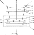
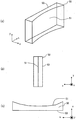
凹シリンドリカルレンズ50は、アクリル樹脂又はポリカーボネート樹脂等の透光性材料によって形成されている。ここで、凹シリンドリカルレンズ50の形状を説明するため、三次元の座標を設定する。図7に示されるように、ヘッドアップディスプレイ装置100に設置された状態において、凹シリンドリカルレンズ50のx軸方向は、上述したX軸方向に沿っている。また凹シリンドリカルレンズ50は、x軸周りに10〜20°程度回転されることにより、光軸OAに対してz軸を傾斜させた姿勢にて、液晶表示部30と凹面鏡40との間に位置している。
The concave
図4及び図6に示されるように、凹シリンドリカルレンズ50は、入射面53及び凹曲面51を有している。入射面53は、液晶表示部30を透過した基画像11の光像を凹シリンドリカルレンズ50内に入射させる。入射面53は、xy平面に沿う平坦面であって、液晶表示部30の表示面31に当接しており、当該表示面31と密着している。凹シリンドリカルレンズ50の液晶表示部30に対する相対位置は、入射面53を表示面31に密着させた状態下でxy平面方向に移動させることにより、基画像11の光像に歪みが生じないように調整される。
As shown in FIGS. 4 and 6, the concave
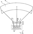
凹曲面51は、z軸方向において入射面53とは反対側に位置する面である。凹曲面51は、光軸OAに沿って、凹面鏡40の反射面41と対向している(図3参照)。凹曲面51は、y軸方向に沿い且つx軸方向おいて凹状に湾曲している。凹曲面51による屈折作用によって、凹シリンドリカルレンズ50は、当該凹曲面51から出射される光を拡散させる。
The concave
また図3に示される凹面鏡40における反射面41の形状は、凹曲面51の形状に基づいて規定されている。詳しく説明すると、基画像11の光像は、凹曲面51において屈折される。そのため、表示像10には、凹曲面51における屈折に起因した歪みが生じ得る。そこで、凹面鏡40における反射面41の形状は、ウィンドシールド90の湾曲によって生じる表示像10の歪みと共に、凹曲面51の湾曲によって生じる表示像10の歪みを補正するように規定されている。
The shape of the reflecting
ここまで説明した凹シリンドリカルレンズ50の凹曲面51は、凹シリンドリカルレンズ50のx軸方向においては凹状に湾曲しているものの、y軸方向に沿った形状である。故に、光軸OAに対するz軸方向の傾斜によって、標準光源20から凹面鏡40に向かう光軸OAに対して垂直となる領域が、凹曲面51に生じない。このような形態において、ウィンドシールド90を透過して反射面41に入射した外乱光ALが当該反射面41によって反射されて凹曲面51に到達した場合が、図7に示されている。外乱光ALは、光軸OAに対して垂直な領域を持たない凹曲面51によって、凹面鏡40とは異なる方向に向けて反射される。
The concave
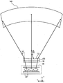
さらに、本実施形態のヘッドアップディスプレイ装置100は、基画像11に対する表示像10の拡大率が複数種類の中から設定される。ヘッドアップディスプレイ装置100における基画像11に対する表示像10の拡大率は、四倍、六倍、八倍の中から選択される。そして、ヘッドアップディスプレイ装置100では、設定される拡大率に応じて凹曲面の曲率半径を規定された凹シリンドリカルレンズ50,150が予め用意されている。さらにヘッドアップディスプレイ装置100では、設定される拡大率に応じて反射面の大きさ及び反射面の曲率半径を規定された凹面鏡40,140,240が予め用意されている(図8〜図10参照)。
Further, in the head-up
凹シリンドリカルレンズ50及び凹面鏡40は、拡大率が八倍に設定された場合に、ヘッドアップディスプレイ装置100に設置される(図8参照)。凹シリンドリカルレンズ150及び凹面鏡140は、拡大率が六倍に設定された場合に、ヘッドアップディスプレイ装置100に設置される(図9参照)。そして、拡大率が四倍に設定された場合には、凹面鏡240がヘッドアップディスプレイ装置100に設置される。拡大率が四倍に設定された場合には、凹シリンドリカルレンズは設置されない(図10参照)。
The concave
図8〜図10に示されるように、基画像11に対する表示像10の拡大率が大きくなるほど、凹シリンドリカルレンズ50における凹曲面51の曲率半径は、小さくされている。これにより、凹曲面51による屈折作用を強めることができるので、凹曲面51の後段における視野角は拡大する。具体的に、八倍の拡大率が想定されることにより形状を規定される凹シリンドリカルレンズ50では、凹曲面51の曲率半径は、30ミリメートルに設定されている。一方、六倍の拡大率が想定されることにより形状を規定される凹シリンドリカルレンズ150では、凹曲面151の曲率半径は、50ミリメートルに設定されている。
As shown in FIGS. 8 to 10, the radius of curvature of the concave
一方、標準光源20及び液晶表示部30は、上述した拡大率にかかわらず同じ仕様のものが用いられる。ヘッドアップディスプレイ装置100では、標準光源20及び液晶表示部30から、各凹面鏡40,140,240までの距離は、拡大率が大きくなるに従い、短くされる。本実施形態では、拡大率が八倍に設定された場合、凹面鏡40に到達する基画像11の光像に要求されるx軸方向及びy軸方向における視野角は、それぞれ(45°,12°)となる。また、拡大率が六倍に設定された場合、凹面鏡140に到達する基画像11の光像に要求されるx軸方向及びy軸方向における視野角は、それぞれ(35°,11°)となる。さらに、拡大率が四倍に設定された場合、凹面鏡240に到達する基画像11の光像に要求されるx軸方向及びy軸方向における視野角は、それぞれ(20°,10°)となる。
On the other hand, the standard
本実施形態では、標準光源20及び液晶表示部30におけるx軸方向における視野角は、複数種類の拡大率のうちで最も小さい拡大率が想定された場合にx軸方向において必要とされる視野角に合わせて規定されている。一方、標準光源20及び液晶表示部30におけるy軸方向における視野角は、複数種類の拡大率のうちで最も大きい拡大率が想定された場合にy軸方向において必要とされる視野角に合わせて規定されている。これらにより、標準光源20及び液晶表示部30のx軸方向及びy軸方向の視野角は、それぞれ(20°,12°)となる。
In the present embodiment, the viewing angle in the x-axis direction of the standard
以上の構成において、ヘッドアップディスプレイ装置100の拡大率が、複数種類の拡大率のうちで最も大きい八倍に設定された場合を説明する。図8に示されるように、標準光源20及び液晶表示部30のx軸方向における視野角は、最も小さい四倍の拡大率が想定された場合にx軸方向において必要とされる20°の視野角に合わせて規定されている。しかし、八倍の拡大率に合わせて凹曲面51の形状が規定された凹シリンドリカルレンズ50は、x軸方向に拡散するよう光を屈折させることにより、視野角を45°にまで拡大させる。これにより、凹シリンドリカルレンズ50を通過した後におけるx軸方向の視野角は、八倍の拡大率が想定された場合にx軸方向において必要とされる45°の視野角を満たしたものになる。
In the above configuration, a case will be described in which the enlargement ratio of the head-up
一方、標準光源20及び液晶表示部30のy軸方向における視野角は、最も大きい八倍の拡大率が想定された場合においてy軸方向に必要とされる12°の視野角に合わせて規定されている。故に、凹シリンドリカルレンズ50がy軸方向に光を拡散することできなくても、y軸方向において必要とされる12°の視野角は、確保され得る。
On the other hand, the viewing angle in the y-axis direction of the standard
次に、ヘッドアップディスプレイ装置100の拡大率が、複数種類の拡大率のうちの中間である六倍に設定された場合を説明する。図9に示されるように、六倍の拡大率に合わせて凹曲面151の形状が規定される凹シリンドリカルレンズ150は、x軸方向に拡散するよう光を屈折させることにより、視野角を35°にまで拡大させる。これにより、凹シリンドリカルレンズ150を通過した後におけるx軸方向の視野角は、六倍の拡大率が想定された場合にx軸方向において必要とされる35°の視野角を満たしたものになる。一方、標準光源20及び液晶表示部30は、y軸方向において12°の視野角を備える。故に、凹シリンドリカルレンズ150がy軸方向に光を拡散することできなくても、y軸方向において必要とされる11°の視野角は、当然に確保され得る。
Next, a case will be described in which the enlargement ratio of the head-up
さらに、ヘッドアップディスプレイ装置100の拡大率が、複数種類の拡大率のうちで最も小さい四倍に設定された場合を説明する。標準光源20及び液晶表示部30のx軸方向における視野角は、最も小さい四倍の拡大率が想定された場合においてx軸方向に必要とされる20°の視野角に合わせて規定されている。故に、図10に示されるように、凹シリンドリカルレンズによる拡散作用を得ることなく、x軸方向において必要な視野角は確保され得る。一方、標準光源20及び液晶表示部30は、y軸方向において12°の視野角を備える。故に、y軸方向において必要とされる10°の視野角は、当然に確保され得る。
Furthermore, the case where the enlargement ratio of the head-up
ここまで説明した本実施形態によれば、凹曲面51の形状及び凹シリンドリカルレンズ50の姿勢によって、凹曲面51にて反射された外乱光ALが基画像11の光像と共にウィンドシールド90に投影されてしまう事態は、抑制される。加えて、光を屈折により拡散させる凹曲面51の作用によって、ウィンドシールド90に投影される表示像10の中央部分と外周部分との輝度差が低減される。これらにより、ヘッドアップディスプレイ装置100は、輝度のむらの低減と、外乱光の映り込みの抑制とが実現された表示像を投影することができる。
According to the present embodiment described so far, the disturbance light AL reflected by the concave
加えて本実施形態によれば、凹面鏡40の有する反射面41の形状は、ウィンドシールド90の湾曲に起因した歪みと共に、凹曲面51の湾曲に起因した歪みも補正するように規定されている。故に、ヘッドアップディスプレイ装置100の構成を複雑化することなく、表示像10の歪みは補正され得る。したがって、ヘッドアップディスプレイ装置100は、輝度むらの低減と外乱光の映り込みの抑制とが図られた歪みの無い表示像10をウィンドシールド90に投影することができる。
In addition, according to the present embodiment, the shape of the reflecting
また本実施形態によれば、表示像10の長手方向であるX軸方向に沿って、凹シリンドリカルレンズ50のx軸方向を向けることにより、当該凹シリンドリカルレンズ50を通過した基画像11の光像は、当該表示像10の長手方向に拡散するよう屈折される。これにより表示像10においては、長手方向であるX軸方向の輝度のむらが低減される。Y軸方向よりもX軸方向に長い横長の表示像10をウィンドシールド90に投影する本実施形態では、当該X軸方向の輝度のむらが顕著になり易い。故に、横長の表示像10を投影するヘッドアップディスプレイ装置100では、凹シリンドリカルレンズ50のx軸方向を、X軸方向に沿わせることが好適なのである。
Further, according to the present embodiment, the optical image of the
さらに本実施形態のように横長の表示像10を表示する形態では、拡大率が大きくなっても、y軸方向に必要とされる視野角は、x軸方向に必要とされる視野角に比べて小さいままである。故に、y軸方向における視野角の確保は、x軸方向における視野角の確保よりも容易である。そのため、主にx軸方向において光を拡散させる作用を発揮する凹シリンドリカルレンズ50,150を用いる形態であっても、表示像10におけるY軸方向(図1等参照)の輝度のむらは、生じ難い。
Further, in the form in which the horizontally
また加えて本実施形態では、標準光源20及び液晶表示部30を共有しても、複数種類の拡大率のそれぞれにおいて、ヘッドアップディスプレイ装置100は、輝度むらの低減された表示像10を表示することができる。したがって、輝度むらの低減及び外乱光ALの映り込み抑制を果たしたヘッドアップディスプレイ装置100の安価な提供が実現できる。
In addition, in this embodiment, even if the standard
さらに加えて本実施形態では、xy平面に沿って平坦な入射面53を液晶表示部30の表示面31に当接させることにより、凹シリンドリカルレンズ50のx軸周り及びy軸周りの回転が抑制される。そのうえで、xy平面に沿って液晶表示部30に対する凹シリンドリカルレンズのxy平面方向の相対位置が調整される。以上により、液晶表示部30に対する凹シリンドリカルレンズ50の位置決めは、正確になされる。故に、液晶表示部30に対する凹シリンドリカルレンズ50の相対位置のずれに起因した表示像10の歪み及び輝度むらは、低減される。
In addition, in this embodiment, the
尚、本実施形態において、標準光源20が特許請求の範囲に記載の「光源部」に相当し、凹面鏡40が特許請求の範囲に記載の「反射鏡部」に相当し、ウィンドシールド90が特許請求の範囲に記載の「表示部材」に相当する。
In this embodiment, the standard
(他の実施形態)
以上、本発明による一実施形態について説明したが、本発明は、上記実施形態に限定して解釈されるものではなく、本発明の要旨を逸脱しない範囲内において種々の実施形態及び組み合わせに適用することができる。
(Other embodiments)
As mentioned above, although one embodiment by the present invention was described, the present invention is not interpreted limited to the above-mentioned embodiment, and is applied to various embodiments and combinations within the range which does not deviate from the gist of the present invention. be able to.
上記実施形態では、凹シリンドリカルレンズ50の入射面53は、当該凹シリンドリカルレンズ50の位置調整のために、xy方向に沿う平坦面とされていた。しかし、凹曲面において光を拡散させる作用を発揮できる凹シリンドリカルレンズであれば、例えば表示面31と対向する入射面は、表示面31に対して凹状に湾曲する曲面であってもよい。又は、入射面は、表示面31に対して凸状に湾曲する曲面であってもよい。さらに、凹シリンドリカルレンズの入射面は、液晶表示部30の表示面31から離間した位置で、例えばヘッドアップディスプレイ装置の筐体(図示しない)に固定されていてもよい。
In the above embodiment, the
上記実施形態では、一枚の各凹面鏡40,140,240が、特許請求の範囲に記載の「反射鏡部」に相当する構成であった。しかし、複数の凹面鏡群及びレンズ群を組み合わせることによって、「反射鏡部」が構成されていてもよい。また、平坦な反射面を有する反射鏡が、「反射鏡部」に用いられていてもよい。 In the said embodiment, each concave mirror 40,140,240 was the structure corresponded to the "reflecting mirror part" as described in a claim. However, the “reflecting mirror portion” may be configured by combining a plurality of concave mirror groups and lens groups. Further, a reflecting mirror having a flat reflecting surface may be used for the “reflecting mirror part”.
上記実施形態では、ヘッドアップディスプレイ装置の拡大率が四倍に設定された場合、凹シリンドリカルレンズは、省略されていた。しかし、標準光源20から凹面鏡40までの距離が上記実施形態よりも短く、大きな視野角が必要とされる形態においては、四倍の拡大率であっても、凹シリンドリカルレンズは設置されてもよい。さらに、ヘッドアップディスプレイ装置に設定される拡大率は、例示した四倍、六倍、八倍に限定されることなく、例えばさらに大きな10倍等であってもよい。さらに、各拡大率において必要とされる視野角は、上記実施形態のものに限定されるものではなく、光源部から反射鏡部までの距離等によって、適宜変更されてよい。
In the above embodiment, the concave cylindrical lens is omitted when the enlargement ratio of the head-up display device is set to four times. However, in a form in which the distance from the standard
上記実施形態では、拡大率が変更された場合であっても、標準光源20及び液晶表示部30は共用されていた。しかし、ヘッドアップディスプレイ装置100に設定される各拡大率において、最適な視野角を備える標準光源及び液晶表示部が、それぞれ用意されていてもよい。
In the above embodiment, the standard
上記実施形態では、凹シリンドリカルレンズ50の凹曲面51は、y軸方向に沿っており、y軸方向において無限大の曲率半径を有していた。しかし、凹シリンドリカルレンズを10°から20°程度の傾斜によって、光軸OAに対して垂直となる領域を凹曲面から無くすことができるのであれば、y軸方向における僅かな湾曲が凹曲面に形成されていてもよい。
In the above embodiment, the concave
上記実施形態では、ウィンドシールド90には横長の表示像10が投影されていた。しかし、縦長の表示像がウィンドシールド90に投影される形態のヘッドアップディスプレイ装置であってもよい。この場合、凹シリンドリカルレンズのx軸方向は、車両の鉛直方向であるY軸方向に沿うように配置されることが望ましい。そして、凹シリンドリカルレンズは、x軸周りに回転されることにより、光軸OAに対してz軸を傾斜させた姿勢にて配置されるのがよい。
In the above embodiment, the horizontally
上記実施形態では、ヘッドアップディスプレイ装置100は、表示像10をウィンドシールド90に投影していた。しかし、例えばインスツルメントパネル91の上面に設置されたコンバイナ等の透光性の板材に、表示像10を投影するヘッドアップディスプレイ装置であってもよい。このような形態では、凹面鏡40の反射面41の曲率は、車種毎に変更されなくてもよくなる。
In the above embodiment, the head-up
上記実施形態では、車両のウィンドシールド90に虚像である表示像10を投影するヘッドアップディスプレイ装置100に本発明を適用した例を示したが、本発明は、各種の輸送機器に搭載され、視認者の前方に表示像10を投影するヘッドアップディスプレイ装置に適用することができる。
In the above-described embodiment, an example in which the present invention is applied to the head-up
10 表示像、11 基画像、16 アイボックス、20 標準光源(光源部)、21 発光ダイオード、22 回路基板、23 インナーレンズ、23a 入射面、23b 出射面、25 拡散板、30 液晶表示部、31 表示面、40,140,240 凹面鏡(反射鏡部)、41, 反射面、50,150 凹シリンドリカルレンズ、51,151 凹曲面、53 入射面、90 ウィンドシールド(表示部材)、91 インスツルメントパネル、100 ヘッドアップディスプレイ装置、OA 光軸、AL 外乱光
DESCRIPTION OF
Claims (4)
前記表示像の基となる基画像を形成する液晶表示部と、
前記液晶表示部の背面側から当該液晶表示部に向けて光を放射する光源部と、
前記液晶表示部を通過した前記基画像の光像を反射することにより、前記表示部材に前記表示像を投影する反射鏡部と、
前記車両の水平方向に沿ってx軸方向を規定した三次元の座標が設定され、y軸方向に沿い且つx軸方向おいて凹状に湾曲し前記反射鏡部と対向する凹曲面を有し、x軸周りに回転させることにより、前記光源部から前記反射鏡部に向かう光軸に対してz軸を傾斜させた姿勢にて、前記液晶表示部と前記反射鏡部との間に位置する凹シリンドリカルレンズと、
を備えることを特徴とするヘッドアップディスプレイ装置。 Is mounted on a vehicle, a head-up display apparatus for projecting a shadow on the display member horizontally long display image in the horizontal direction than the vertical direction of the vehicle,
A liquid crystal display unit for forming a base image as a base of the display image;
A light source unit that emits light from the back side of the liquid crystal display unit toward the liquid crystal display unit;
A reflecting mirror that projects the display image onto the display member by reflecting the light image of the base image that has passed through the liquid crystal display;
A three-dimensional coordinate defining the x-axis direction along the horizontal direction of the vehicle is set, and has a concave curved surface that curves in a concave shape along the y-axis direction and in the x-axis direction and faces the reflecting mirror part; A recess positioned between the liquid crystal display unit and the reflecting mirror unit in a posture in which the z axis is inclined with respect to the optical axis from the light source unit toward the reflecting mirror unit by rotating around the x axis. A cylindrical lens,
A head-up display device comprising:
当該設定された拡大率に応じて前記凹曲面の曲率半径を規定された前記凹シリンドリカルレンズが前記液晶表示部と前記反射鏡部との間に位置し、
光軸に対してx軸方向及びy軸方向に角度を持って出射される光のうち、光軸に沿う方向に出射される光に対して所定の強度比を維持している当該角度の範囲が、視野角として規定され、
前記x軸方向における視野角は、複数種類の拡大率のうちで最も小さい拡大率が想定された場合にx軸方向において必要とされる視野角に合わせて規定され、
前記y軸方向における視野角は、複数種類の拡大率のうちで最も大きい拡大率が想定された場合にy軸方向において必要とされる視野角に合わせて規定されることを特徴とする請求項1に記載のヘッドアップディスプレイ装置。 A head-up display device in which an enlargement ratio of the display image with respect to the base image is set from a plurality of types,
The concave cylindrical lens in which the radius of curvature of the concave curved surface is defined according to the set magnification is positioned between the liquid crystal display unit and the reflecting mirror unit;
Among the light emitted with an angle in the x-axis direction and the y-axis direction with respect to the optical axis, a range of the angle maintaining a predetermined intensity ratio with respect to the light emitted in the direction along the optical axis Is defined as the viewing angle,
The viewing angle in the x-axis direction is defined according to the viewing angle required in the x-axis direction when the smallest magnification among a plurality of types of magnification is assumed.
The viewing angle in the y-axis direction is defined according to a viewing angle required in the y-axis direction when the largest magnification among a plurality of types of magnifications is assumed. 2. The head-up display device according to 1.
前記反射鏡部は、前記ウィンドシールドの湾曲及び前記凹曲面の湾曲によって生じる前記表示像の歪みを補正するように形状を規定される反射面、を有することを特徴とする請求項1又は2に記載のヘッドアップディスプレイ装置。 A head-up display device that is mounted on a vehicle and projects the display image onto a curved windshield as the display member,
3. The reflecting surface according to claim 1, wherein the reflecting mirror portion has a reflecting surface whose shape is defined so as to correct distortion of the display image caused by the curvature of the windshield and the curvature of the concave curved surface. The head-up display device described.
前記液晶表示部の表示面に当接し、当該液晶表示部を透過した前記基画像の光像を当該凹シリンドリカルレンズ内に入射させる、xy平面に沿う平坦な入射面、を有することを特徴とする請求項1〜3のいずれか一項に記載のヘッドアップディスプレイ装置。 The concave cylindrical lens is
The contact with the display surface of the liquid crystal display unit, light is incident image of the base image that has passed through the liquid crystal display unit in those concave cylindrical lens, characterized Rukoto to have a flat entrance surface along the xy plane The head-up display apparatus as described in any one of Claims 1-3 .
Priority Applications (3)
| Application Number | Priority Date | Filing Date | Title |
|---|---|---|---|
| JP2010239815A JP5287828B2 (en) | 2010-10-26 | 2010-10-26 | Head-up display device |
| US13/278,352 US9004691B2 (en) | 2010-10-26 | 2011-10-21 | Head-up display device using a concave cylindrical lens for projecting image on screen |
| KR1020110109363A KR101274891B1 (en) | 2010-10-26 | 2011-10-25 | Head-up display device for projecting image on screen |
Applications Claiming Priority (1)
| Application Number | Priority Date | Filing Date | Title |
|---|---|---|---|
| JP2010239815A JP5287828B2 (en) | 2010-10-26 | 2010-10-26 | Head-up display device |
Publications (2)
| Publication Number | Publication Date |
|---|---|
| JP2012093506A JP2012093506A (en) | 2012-05-17 |
| JP5287828B2 true JP5287828B2 (en) | 2013-09-11 |
Family
ID=45972739
Family Applications (1)
| Application Number | Title | Priority Date | Filing Date |
|---|---|---|---|
| JP2010239815A Expired - Fee Related JP5287828B2 (en) | 2010-10-26 | 2010-10-26 | Head-up display device |
Country Status (3)
| Country | Link |
|---|---|
| US (1) | US9004691B2 (en) |
| JP (1) | JP5287828B2 (en) |
| KR (1) | KR101274891B1 (en) |
Cited By (1)
| Publication number | Priority date | Publication date | Assignee | Title |
|---|---|---|---|---|
| CN106646891A (en) * | 2017-03-21 | 2017-05-10 | 上海乐蜗信息科技有限公司 | Virtual reality equipment |
Families Citing this family (45)
| Publication number | Priority date | Publication date | Assignee | Title |
|---|---|---|---|---|
| JP5941292B2 (en) * | 2012-02-10 | 2016-06-29 | 矢崎総業株式会社 | Vehicle display device |
| TWI459356B (en) * | 2012-08-31 | 2014-11-01 | Nat Univ Tsing Hua | A sectional dynamic-driving backlight module and a head-up display device thereof |
| JP5741540B2 (en) | 2012-09-04 | 2015-07-01 | 株式会社デンソー | Head-up display device |
| JP5783155B2 (en) | 2012-10-05 | 2015-09-24 | 株式会社デンソー | Display device |
| DE102013203616B4 (en) * | 2013-03-04 | 2019-10-24 | Sypro Optics Gmbh | Apparatus for projecting an image into a display area with screen for intermediate image display |
| JP6226603B2 (en) * | 2013-07-22 | 2017-11-08 | パイオニア株式会社 | Head-up display |
| JP6268835B2 (en) * | 2013-09-11 | 2018-01-31 | 大日本印刷株式会社 | Head-up display display unit |
| JP6127912B2 (en) * | 2013-10-28 | 2017-05-17 | 株式会社Jvcケンウッド | Image display device |
| EP2869112A1 (en) * | 2013-10-30 | 2015-05-06 | Johnson Controls GmbH | Projection screen for projecting an image and method for adapting a projections screen |
| WO2015186488A1 (en) * | 2014-06-03 | 2015-12-10 | 矢崎総業株式会社 | Projection display device for vehicle |
| KR20160018917A (en) * | 2014-08-07 | 2016-02-18 | 현대자동차주식회사 | Lamp for vehicle |
| JP6375825B2 (en) | 2014-09-23 | 2018-08-22 | 株式会社デンソー | Head-up display device |
| JP6550716B2 (en) | 2014-10-16 | 2019-07-31 | 日本精機株式会社 | Head-up display device |
| JP6409511B2 (en) * | 2014-11-04 | 2018-10-24 | 日本精機株式会社 | Head-up display device |
| EP3070510B1 (en) * | 2014-12-08 | 2018-12-12 | Panasonic Intellectual Property Management Co., Ltd. | Head-up display, illuminating device and vehicle equipped with the same |
| JP6282986B2 (en) * | 2015-01-26 | 2018-02-21 | カルソニックカンセイ株式会社 | Head-up display device |
| WO2016136407A1 (en) * | 2015-02-27 | 2016-09-01 | ソニー株式会社 | Optical device and image display device |
| CN105954873A (en) * | 2015-03-09 | 2016-09-21 | 矽创电子股份有限公司 | Optical imaging device |
| JP6465353B2 (en) * | 2015-04-28 | 2019-02-06 | 日本精機株式会社 | Head-up display device |
| JP6551730B2 (en) * | 2015-04-28 | 2019-07-31 | 株式会社リコー | Image display device and moving body |
| WO2017022176A1 (en) * | 2015-08-06 | 2017-02-09 | パナソニックIpマネジメント株式会社 | Head-up display and moving body equipped with head-up display |
| JPWO2017061040A1 (en) * | 2015-10-09 | 2018-08-16 | マクセル株式会社 | Projection optical system and head-up display device |
| CN109477968B (en) * | 2016-07-07 | 2021-08-13 | 麦克赛尔株式会社 | head-up display |
| JP6762807B2 (en) | 2016-08-30 | 2020-09-30 | マクセル株式会社 | Information display device |
| JP2018084596A (en) * | 2016-11-21 | 2018-05-31 | マクセル株式会社 | Information display device |
| JP2019008203A (en) * | 2017-06-27 | 2019-01-17 | 矢崎総業株式会社 | Vehicle display device |
| WO2019008684A1 (en) | 2017-07-04 | 2019-01-10 | マクセル株式会社 | Projection optical system and head-up display device |
| JP6791058B2 (en) * | 2017-08-09 | 2020-11-25 | 株式会社デンソー | 3D display device |
| JP2019045605A (en) * | 2017-08-31 | 2019-03-22 | 国立大学法人東北大学 | Head-up display device |
| DE102017120598A1 (en) * | 2017-09-07 | 2019-03-07 | Valeo Schalter Und Sensoren Gmbh | Head-up display with diffuser for a vehicle |
| US10303045B1 (en) | 2017-12-20 | 2019-05-28 | Micron Technology, Inc. | Control of display device for autonomous vehicle |
| JP6993068B2 (en) * | 2018-01-09 | 2022-01-13 | アルパイン株式会社 | Display system |
| JP7202539B2 (en) | 2018-03-19 | 2023-01-12 | 株式会社リコー | Image display device, image projection device and moving body |
| TWI816758B (en) * | 2018-05-10 | 2023-10-01 | 日商索尼股份有限公司 | Image display device, projection optical system and image display system |
| JP7035940B2 (en) * | 2018-09-28 | 2022-03-15 | 株式会社Jvcケンウッド | Head-up display device |
| FR3094098A1 (en) * | 2019-03-22 | 2020-09-25 | Valeo Comfort And Driving Assistance | Head-up display with curved screen |
| US12325302B2 (en) * | 2019-10-21 | 2025-06-10 | Maxell, Ltd. | Light source apparatus, and information display system and head-up display apparatus using the same |
| JP7018922B2 (en) * | 2019-12-04 | 2022-02-14 | マクセル株式会社 | Head-up display device |
| JP7278447B2 (en) * | 2020-07-22 | 2023-05-19 | マクセル株式会社 | vehicle |
| JP7090127B2 (en) * | 2020-07-22 | 2022-06-23 | マクセル株式会社 | Optical system and head-up display device |
| JP7374273B2 (en) * | 2020-09-09 | 2023-11-06 | マクセル株式会社 | information display device |
| CN113534465B (en) * | 2021-07-08 | 2025-02-07 | 合肥疆程技术有限公司 | Backlight system, vehicle head-up display and vehicle |
| TWI788049B (en) * | 2021-10-13 | 2022-12-21 | 怡利電子工業股份有限公司 | Directional backlit display device with eye tracking |
| JP7485828B2 (en) * | 2022-03-07 | 2024-05-16 | マクセル株式会社 | vehicle |
| CN116107088B (en) * | 2022-11-15 | 2025-07-29 | 浙江炽云科技有限公司 | Head-up display device and head-up display system |
Family Cites Families (16)
| Publication number | Priority date | Publication date | Assignee | Title |
|---|---|---|---|---|
| US3887273A (en) * | 1973-07-27 | 1975-06-03 | Friedemann Conrad J | Speedometer optical projection system |
| JPS63182935A (en) | 1987-01-26 | 1988-07-28 | Hitachi Cable Ltd | Handshake communication method in circuit switched loop network |
| JPS63182935U (en) * | 1987-05-19 | 1988-11-25 | ||
| JP2922604B2 (en) * | 1990-08-24 | 1999-07-26 | 矢崎総業株式会社 | Display device for vehicles |
| JPH05341226A (en) * | 1992-06-11 | 1993-12-24 | Fujitsu Ltd | Head up display |
| KR960031223A (en) * | 1995-02-17 | 1996-09-17 | 아시이 쇼주 | Remote display for vehicles |
| JP2000056254A (en) | 1998-08-06 | 2000-02-25 | Asahi Glass Co Ltd | Information display device |
| JP2002202475A (en) * | 2000-12-28 | 2002-07-19 | Yazaki Corp | Display device for vehicles |
| JP2004126025A (en) | 2002-09-30 | 2004-04-22 | Nippon Seiki Co Ltd | Display device |
| JP2003215552A (en) * | 2002-11-01 | 2003-07-30 | Matsushita Electric Ind Co Ltd | Image display device, view finder using the same, and projection type display device |
| JP4437675B2 (en) | 2003-12-26 | 2010-03-24 | 日本精機株式会社 | Lighting device |
| WO2005083493A1 (en) * | 2004-02-27 | 2005-09-09 | Matsushita Electric Industrial Co., Ltd. | Illuminating light source and two-dimensional image display using same |
| DE102005012011A1 (en) * | 2005-03-16 | 2006-09-28 | Carl Zeiss Jena Gmbh | Projection unit for a head-up display |
| JP4760336B2 (en) | 2005-11-29 | 2011-08-31 | 株式会社デンソー | Head-up display device |
| JP2007272061A (en) * | 2006-03-31 | 2007-10-18 | Denso Corp | Head-up display device |
| JP5125147B2 (en) * | 2007-02-27 | 2013-01-23 | 株式会社日立製作所 | Projection display |
-
2010
- 2010-10-26 JP JP2010239815A patent/JP5287828B2/en not_active Expired - Fee Related
-
2011
- 2011-10-21 US US13/278,352 patent/US9004691B2/en not_active Expired - Fee Related
- 2011-10-25 KR KR1020110109363A patent/KR101274891B1/en not_active Expired - Fee Related
Cited By (1)
| Publication number | Priority date | Publication date | Assignee | Title |
|---|---|---|---|---|
| CN106646891A (en) * | 2017-03-21 | 2017-05-10 | 上海乐蜗信息科技有限公司 | Virtual reality equipment |
Also Published As
| Publication number | Publication date |
|---|---|
| KR20120068687A (en) | 2012-06-27 |
| US20120099032A1 (en) | 2012-04-26 |
| KR101274891B1 (en) | 2013-06-17 |
| JP2012093506A (en) | 2012-05-17 |
| US9004691B2 (en) | 2015-04-14 |
Similar Documents
| Publication | Publication Date | Title |
|---|---|---|
| JP5287828B2 (en) | Head-up display device | |
| US8736964B2 (en) | Head-up display apparatus | |
| JP6589890B2 (en) | Head-up display device | |
| JP6465353B2 (en) | Head-up display device | |
| JP2014149405A (en) | Head-up display device | |
| JP6601431B2 (en) | Head-up display device | |
| JP7587034B2 (en) | Space floating image display device and light source device | |
| JP7587417B2 (en) | Space floating image display device and light source device | |
| CN106716228A (en) | Head-up display device | |
| JPWO2016092724A1 (en) | Head-up display, lighting device, and moving body equipped with the same | |
| US20190031028A1 (en) | Head-up display device | |
| US11561396B2 (en) | Head-up display device and transportation device | |
| WO2022185927A1 (en) | Spatial floating image display device | |
| US20180252915A1 (en) | Head-up display device with narrow angle diffusion sheet | |
| KR102706046B1 (en) | Display devices, head-up displays and automobiles | |
| JP2016180922A (en) | Head-up display device | |
| TWI802087B (en) | Image generating unit and head-up display therefor | |
| US11092803B2 (en) | Head-up display device with reflecting target diffuser sheet | |
| US12072488B2 (en) | Display device, head-up display, and mobile object | |
| WO2022019048A1 (en) | Image generation apparatus and head-up display | |
| JP2015060015A (en) | Head-up display device | |
| US20260118716A1 (en) | Display device and head-up display apparatus | |
| JP7495702B2 (en) | Lighting equipment | |
| JP2025170457A (en) | Virtual image display device | |
| CN120981758A (en) | Head-up display for vehicles with a screen that provides precise and low-loss reflection in a projector-based image generator. |
Legal Events
| Date | Code | Title | Description |
|---|---|---|---|
| A621 | Written request for application examination |
Free format text: JAPANESE INTERMEDIATE CODE: A621 Effective date: 20120809 |
|
| A977 | Report on retrieval |
Free format text: JAPANESE INTERMEDIATE CODE: A971007 Effective date: 20121127 |
|
| A131 | Notification of reasons for refusal |
Free format text: JAPANESE INTERMEDIATE CODE: A131 Effective date: 20121204 |
|
| A521 | Request for written amendment filed |
Free format text: JAPANESE INTERMEDIATE CODE: A523 Effective date: 20130130 |
|
| TRDD | Decision of grant or rejection written | ||
| A01 | Written decision to grant a patent or to grant a registration (utility model) |
Free format text: JAPANESE INTERMEDIATE CODE: A01 Effective date: 20130507 |
|
| A61 | First payment of annual fees (during grant procedure) |
Free format text: JAPANESE INTERMEDIATE CODE: A61 Effective date: 20130520 |
|
| R151 | Written notification of patent or utility model registration |
Ref document number: 5287828 Country of ref document: JP Free format text: JAPANESE INTERMEDIATE CODE: R151 |
|
| R250 | Receipt of annual fees |
Free format text: JAPANESE INTERMEDIATE CODE: R250 |
|
| R250 | Receipt of annual fees |
Free format text: JAPANESE INTERMEDIATE CODE: R250 |
|
| R250 | Receipt of annual fees |
Free format text: JAPANESE INTERMEDIATE CODE: R250 |
|
| R250 | Receipt of annual fees |
Free format text: JAPANESE INTERMEDIATE CODE: R250 |
|
| LAPS | Cancellation because of no payment of annual fees |