JP5287403B2 - Information processing apparatus, information processing method, and program - Google Patents
Information processing apparatus, information processing method, and program Download PDFInfo
- Publication number
- JP5287403B2 JP5287403B2 JP2009068620A JP2009068620A JP5287403B2 JP 5287403 B2 JP5287403 B2 JP 5287403B2 JP 2009068620 A JP2009068620 A JP 2009068620A JP 2009068620 A JP2009068620 A JP 2009068620A JP 5287403 B2 JP5287403 B2 JP 5287403B2
- Authority
- JP
- Japan
- Prior art keywords
- detection area
- state
- display panel
- detected
- selected state
- Prior art date
- Legal status (The legal status is an assumption and is not a legal conclusion. Google has not performed a legal analysis and makes no representation as to the accuracy of the status listed.)
- Expired - Fee Related
Links
Images


Classifications
-
- G—PHYSICS
- G06—COMPUTING; CALCULATING OR COUNTING
- G06F—ELECTRIC DIGITAL DATA PROCESSING
- G06F3/00—Input arrangements for transferring data to be processed into a form capable of being handled by the computer; Output arrangements for transferring data from processing unit to output unit, e.g. interface arrangements
- G06F3/01—Input arrangements or combined input and output arrangements for interaction between user and computer
- G06F3/03—Arrangements for converting the position or the displacement of a member into a coded form
- G06F3/041—Digitisers, e.g. for touch screens or touch pads, characterised by the transducing means
- G06F3/0412—Digitisers structurally integrated in a display
-
- G—PHYSICS
- G06—COMPUTING; CALCULATING OR COUNTING
- G06F—ELECTRIC DIGITAL DATA PROCESSING
- G06F3/00—Input arrangements for transferring data to be processed into a form capable of being handled by the computer; Output arrangements for transferring data from processing unit to output unit, e.g. interface arrangements
- G06F3/01—Input arrangements or combined input and output arrangements for interaction between user and computer
- G06F3/048—Interaction techniques based on graphical user interfaces [GUI]
- G06F3/0487—Interaction techniques based on graphical user interfaces [GUI] using specific features provided by the input device, e.g. functions controlled by the rotation of a mouse with dual sensing arrangements, or of the nature of the input device, e.g. tap gestures based on pressure sensed by a digitiser
- G06F3/0488—Interaction techniques based on graphical user interfaces [GUI] using specific features provided by the input device, e.g. functions controlled by the rotation of a mouse with dual sensing arrangements, or of the nature of the input device, e.g. tap gestures based on pressure sensed by a digitiser using a touch-screen or digitiser, e.g. input of commands through traced gestures
Description
本発明は、情報処理装置、情報処理方法、およびプログラムに関する。 The present invention relates to an information processing apparatus, an information processing method, and a program.
従来のタッチパネル(表示パネル)では、指、スタイラス等の操作体によるタッチパネルに対する接触状態を検知することで、タッチパネルに表示されているオブジェクトの選択等、ユーザと機器間でのインタラクションが行われる。一方、操作体による近接状態を検知することで、ユーザと機器間でのインタラクションを可能にする形式のタッチパネルが知られている。 In a conventional touch panel (display panel), interaction between the user and the device, such as selection of an object displayed on the touch panel, is performed by detecting a contact state with respect to the touch panel by an operation body such as a finger or a stylus. On the other hand, there is known a touch panel of a type that enables interaction between a user and a device by detecting a proximity state by an operating body.
しかしながら、一般に、近接状態の検知では、接触状態の検知に比べて操作体の位置情報の検出精度が低下してしまう。このため、操作体の僅かな動作により、オブジェクト毎に設定されている検知領域の内部で検知されていた操作体が外部で検知され、または検知領域の外部で検知されていた操作体が内部で検知されることで、誤操作が発生してしまう場合がある。特に、選択対象であるオブジェクトの検知領域内で検知されていた操作体が、選択対象でないオブジェクトの検知領域内で検知されると、選択対象であるオブジェクトの代わりに選択対象でないオブジェクトが選択状態にされてしまい、誤操作が発生してしまう場合がある。 However, in general, in the detection of the proximity state, the detection accuracy of the position information of the operating tool is lower than in the detection of the contact state. For this reason, the operation body detected inside the detection area set for each object is detected outside by the slight movement of the operation body, or the operation body detected outside the detection area is inside. An erroneous operation may occur due to the detection. In particular, when an operation object that has been detected in the detection area of the object that is the selection target is detected in the detection area of the object that is not the selection target, the object that is not the selection target is put in the selected state instead of the object that is the selection target. May result in erroneous operation.
そこで、本発明は、操作体の近接状態を検知するタッチパネルの操作性を向上可能な、情報処理装置、情報処理方法、およびプログラムを提供しようとするものである。 Therefore, the present invention intends to provide an information processing apparatus, an information processing method, and a program capable of improving the operability of a touch panel that detects the proximity state of an operating tool.
本発明の第1の観点によれば、選択状態または非選択状態にある1以上のオブジェクトが表示される表示パネルと、オブジェクトの表示領域を含む第1の検知領域、および第1の検知領域を含み第1の検知領域より大きな第2の検知領域を、表示パネル上でオブジェクト毎に設定する検知領域設定部と、表示パネル上に近接する操作体を検知する操作体検知部と、非選択状態にあるオブジェクトの第1の検知領域内で操作体が検知される場合に、オブジェクトを選択状態にし、選択状態にあるオブジェクトの第2の検知領域内で操作体が検知されない場合に、オブジェクトを非選択状態にする状態管理部と、を備える情報処理装置が提供される。 According to the first aspect of the present invention, a display panel on which one or more objects in a selected state or a non-selected state are displayed, a first detection region including a display region of the objects, and a first detection region are provided. A detection area setting unit that sets a second detection area that is larger than the first detection area for each object on the display panel, an operation object detection unit that detects an operation object close to the display panel, and a non-selected state When the operating body is detected in the first detection area of the object in the area, the object is selected, and when the operating body is not detected in the second detection area of the object in the selected state, the object is hidden. An information processing apparatus is provided that includes a state management unit for selecting a state.
かかる構成によれば、情報処理装置は、非選択状態にあるオブジェクトを、第1の検知領域内で操作体が検知されるまで選択状態とせず、選択状態にあるオブジェクトを、第1の検知領域内で操作体が検知されなくても第2の検知領域内で操作体が検知されている限り非選択状態としない。これにより、選択対象でないオブジェクトが誤って選択状態にされ難くなるとともに、選択対象であるオブジェクトが誤って非選択状態にされ難くなる。よって、操作体の僅かな動作に伴う誤操作の発生が防止されることで、タッチパネルの操作性を向上させることができる。 According to this configuration, the information processing apparatus does not select the object in the non-selected state until the operating body is detected in the first detection region, and does not select the object in the selected state in the first detection region. Even if the operating tool is not detected within the second detection area, the non-selected state is not set as long as the operating tool is detected within the second detection region. This makes it difficult for an object that is not a selection target to be erroneously selected, and makes it difficult for an object that is a selection target to be erroneously unselected. Therefore, it is possible to improve the operability of the touch panel by preventing the occurrence of an erroneous operation associated with a slight operation of the operating body.
また、上記検知領域設定部は、表示パネルに対して水平方向でオブジェクトの表示領域を含む第1の検知領域、および第1の検知領域を含み表示パネルに対して水平方向で第1の検知領域よりも外側に拡がる第2の検知領域を、表示パネル上でオブジェクト毎に設定し、上記状態管理部は、非選択状態にあるオブジェクトの第1の検知領域内で、表示パネルから所定の垂直距離内に近接する操作体が検知された場合に、オブジェクトを選択状態にし、選択状態にあるオブジェクトの第2の検知領域内で、表示パネルから所定の垂直距離内に近接する操作体が検知されない場合に、オブジェクトを非選択状態にしてもよい。これにより、表示パネルに対して水平方向で第1および第2の検知領域を設定し、検知領域内における操作体の検知状況に応じて、オブジェクトを選択状態/非選択状態にすることで、表示パネルに対して水平方向での操作体の僅かな動作に伴う誤操作の発生を防止することができる。 The detection area setting unit includes a first detection area including an object display area in the horizontal direction with respect to the display panel, and a first detection area including the first detection area in the horizontal direction with respect to the display panel. A second detection area that extends outward from the display panel is set for each object on the display panel, and the state management unit sets a predetermined vertical distance from the display panel within the first detection area of the object in the non-selected state. When an operation body that is close to the inside is detected, the object is selected, and an operation body that is close within a predetermined vertical distance from the display panel is not detected within the second detection area of the selected object. In addition, the object may be in a non-selected state. Thereby, the first and second detection areas are set in the horizontal direction with respect to the display panel, and the object is selected / unselected according to the detection state of the operating body in the detection area, thereby displaying It is possible to prevent an erroneous operation caused by a slight operation of the operating body in the horizontal direction with respect to the panel.
また、上記検知領域設定部は、表示パネルに対して水平方向および垂直方向でオブジェクトの表示領域を含む第1の検知領域、および第1の検知領域を含み表示パネルに対して水平方向で第1の検知領域よりも外側に拡がり、かつ表示パネルに対して垂直方向で第1の検知領域よりも表示パネルから離間して拡がる第2の検知領域を、表示パネル上でオブジェクト毎に設定し、上記状態管理部は、非選択状態にあるオブジェクトの第1の検知領域内で操作体が検知された場合に、オブジェクトを選択状態にし、選択状態にあるオブジェクトの第2の検知領域内で操作体が検知されない場合に、オブジェクトを非選択状態にしてもよい。これにより、表示パネルに対して水平方向および垂直方向で第1および第2の検知領域を設定し、検知領域内における操作体の検知状況に応じて、オブジェクトを選択状態/非選択状態にすることで、表示パネルに対して水平方向および垂直方向での操作体の僅かな動作に伴う誤操作の発生を防止することができる。 The detection area setting unit includes a first detection area including an object display area in a horizontal direction and a vertical direction with respect to the display panel, and a first detection area including the first detection area in the horizontal direction with respect to the display panel. A second detection area extending outside the detection area and extending away from the display panel in a direction perpendicular to the display panel and extending from the display panel for each object on the display panel, and The state management unit sets the object in the selected state when the operating body is detected in the first detection area of the object in the non-selected state, and the operating body is in the second detection area of the object in the selected state. If it is not detected, the object may be in a non-selected state. Thus, the first and second detection areas are set in the horizontal direction and the vertical direction with respect to the display panel, and the object is selected / unselected according to the detection state of the operating body in the detection area. Thus, it is possible to prevent an erroneous operation caused by a slight operation of the operating body in the horizontal direction and the vertical direction with respect to the display panel.
また、上記操作体検知部は、表示パネル上に近接して移動する操作体の移動履歴を検知し、上記検知領域設定部は、操作体の移動履歴に応じて、第1の検知領域および/または第2の検知領域を表示パネル上でオブジェクト毎に設定してもよい。これにより、操作体の移動履歴に応じて、オブジェクトの第1および第2の検知領域を設定することで、操作体の僅かな動作に伴う誤操作の発生を防止することができる。 Further, the operating tool detection unit detects a movement history of the operating tool that moves close to the display panel, and the detection area setting unit detects the first detection area and / or the detection history according to the movement history of the operating tool. Alternatively, the second detection area may be set for each object on the display panel. Thus, by setting the first and second detection areas of the object according to the movement history of the operating body, it is possible to prevent an erroneous operation associated with a slight operation of the operating body.
また、上記検知領域設定部は、第1の方向から第2の方向に向けて、オブジェクトの第1の検知領域の外部から内部に移動してくる操作体が第1の検知領域の内部で検知された場合に、オブジェクトの第2の検知領域を第1の方向で第2の検知領域の外側に拡張してもよい。これにより、操作体の移動履歴からユーザによるオブジェクトの選択意図を推定し、第2の検知領域を第1の方向で第2の検知領域の外側に拡張することで、選択対象であるオブジェクトが誤って非選択状態にされることを防止することができる。 In addition, the detection area setting unit detects an operation body moving from the outside of the first detection area of the object toward the second direction from the first direction to the inside of the first detection area. In this case, the second detection area of the object may be extended outside the second detection area in the first direction. As a result, the user's intention to select the object is estimated from the movement history of the operating tool, and the second detection area is expanded outside the second detection area in the first direction, so that the object to be selected is erroneously displayed. Thus, the non-selected state can be prevented.
また、上記検知領域設定部は、第1の方向から第2の方向に向けて、オブジェクトの第1の検知領域の内部から外部に移動していく操作体が第1の検知領域の外部で検知された場合に、オブジェクトの第1の検知領域を第1の方向で第1の検知領域の内側に縮小してもよい。これにより、操作体の移動履歴からユーザによるオブジェクトの非選択意図を推定し、第1の検知領域を第1の方向で第1の検知領域の内側に縮小することで、選択対象でないオブジェクトが誤って選択状態にされることを防止することができる。 Further, the detection area setting unit detects an operating body moving from the inside of the first detection area of the object to the outside from the first direction to the second direction outside the first detection area. In such a case, the first detection area of the object may be reduced inward of the first detection area in the first direction. As a result, the non-selection intention of the object by the user is estimated from the movement history of the operating tool, and the first detection area is reduced to the inside of the first detection area in the first direction. Thus, it is possible to prevent the selection state.
また、上記状態管理部は、選択状態にある第1のオブジェクトの第2の検知領域と、非選択状態にある第2のオブジェクトの第1の検知領域とが重複する領域で操作体が検知された場合に、第1のオブジェクトの選択状態を維持してもよい。これにより、第1のオブジェクトの選択状態を維持することで、選択対象であるオブジェクトが誤って非選択状態にされることを防止することができる。 In addition, the state management unit detects an operating body in an area where the second detection area of the first object in the selected state overlaps the first detection area of the second object in the non-selected state. In this case, the selected state of the first object may be maintained. Thereby, by maintaining the selection state of the first object, it is possible to prevent the object to be selected from being erroneously set to the non-selection state.
本発明の第2の観点によれば、選択状態または非選択状態にある1以上のオブジェクトを表示パネルに表示し、オブジェクトの表示領域を含む第1の検知領域、および第1の検知領域を含み第1の検知領域より大きな第2の検知領域を、表示パネルでオブジェクト毎に設定し、表示パネル上に近接する操作体を検知し、非選択状態にあるオブジェクトの第1の検知領域内で操作体が検知される場合に、オブジェクトを選択状態にし、選択状態にあるオブジェクトの第2の検知領域内で操作体が検知されない場合に、オブジェクトを非選択状態にする情報処理方法が提供される。 According to a second aspect of the present invention, one or more objects in a selected state or a non-selected state are displayed on a display panel, and include a first detection region including a display region of the object, and a first detection region. A second detection area that is larger than the first detection area is set for each object on the display panel, an operating body that is close to the display panel is detected, and an operation is performed within the first detection area of the object that is in a non-selected state. An information processing method is provided in which an object is selected when a body is detected, and an object is not selected when an operating body is not detected in the second detection area of the object in the selected state.
かかる方法によれば、非選択状態にあるオブジェクトは、第1の検知領域内で操作体が検知されるまで選択状態とならず、選択状態にあるオブジェクトは、第1の検知領域内で操作体が検知されなくても第2の検知領域内で操作体が検知されている限り非選択状態とならない。これにより、選択対象でないオブジェクトが誤って選択状態にされ難くなるとともに、選択対象であるオブジェクトが誤って非選択状態にされ難くなる。よって、操作体の僅かな動作に伴う誤操作の発生が防止されることで、タッチパネルの操作性を向上させることができる。 According to this method, the object in the non-selected state is not in the selected state until the operating body is detected in the first detection area, and the object in the selected state is not in the operating body in the first detection area. Even if is not detected, as long as the operating tool is detected in the second detection region, the non-selected state is not obtained. This makes it difficult for an object that is not a selection target to be erroneously selected, and makes it difficult for an object that is a selection target to be erroneously unselected. Therefore, it is possible to improve the operability of the touch panel by preventing the occurrence of an erroneous operation associated with a slight operation of the operating body.
本発明の第3の観点によれば、本発明の第2の観点による情報処理方法をコンピュータに実行させるためのプログラムが提供される。 According to a third aspect of the present invention, there is provided a program for causing a computer to execute the information processing method according to the second aspect of the present invention.
以上説明したように本発明によれば、操作体の近接状態を検知するタッチパネルの操作性を向上可能な、情報処理装置、情報処理方法、およびプログラムを提供することができる。 As described above, according to the present invention, it is possible to provide an information processing apparatus, an information processing method, and a program capable of improving the operability of a touch panel that detects the proximity state of an operating tool.
以下に、添付した図面を参照しながら、本発明の好適な実施形態について詳細に説明する。なお、本明細書および図面において、実質的に同一の機能構成を有する構成要素については、同一の符号を付することにより重複説明を省略する。 Hereinafter, preferred embodiments of the present invention will be described in detail with reference to the accompanying drawings. In the present specification and drawings, components having substantially the same functional configuration are denoted by the same reference numerals, and redundant description is omitted.
[1.情報処理装置100の概要]
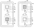
図1は、本発明の一実施形態に係る情報処理装置100の概要を示す図である。図1に示すように、本発明の一実施形態に係る情報処理装置100は、指、スタイラス等の操作体Mによる近接状態を検知可能なタッチパネル(表示パネル)110を有する。なお、以下では、情報処理装置100に内蔵式のタッチパネル110が設けられる場合について説明するが、情報処理装置100には、通信手段を介して外付けされるタッチパネル110が設けられてもよい。
[1. Overview of information processing apparatus 100]
FIG. 1 is a diagram showing an overview of an
情報処理装置100は、アイコン等の1以上のオブジェクトOをタッチパネル110に表示し、オブジェクトOの表示領域を含む検知領域Aをタッチパネル110上でオブジェクトO毎に設定する。情報処理装置100は、タッチパネル110上に近接する操作体Mを検知し、オブジェクトOの検知領域A内での操作体Mの検知状況に応じて、オブジェクトOを選択状態または非選択状態にする(以下では、選択状態および非選択状態にあるオブジェクトが濃いハッチングおよび薄いハッチングで各々に表される。)。なお、オブジェクトOには、例えば、アイコン、ボタン、サムネイル等、グラフィカルユーザインタフェースを構成する任意のオブジェクトが含まれる。
The
ここで、情報処理装置100は、オブジェクトOの表示領域を含む検知領域A1と併せて、検知領域A1を含み検知領域A1より大きな検知領域A2を、タッチパネル110上でオブジェクトO毎に設定する。そして、情報処理装置100は、図1の左側に示すように、非選択状態(薄いハッチング)にあるオブジェクトOの検知領域A1内で操作体Mが検知される場合に、オブジェクトOを選択状態にする。また、情報処理装置100は、図1の右側に示すように、選択状態(濃いハッチング)にあるオブジェクトOの検知領域A2内で操作体Mが検知されない場合に、オブジェクトOを非選択状態にする。
Here, the
これにより、非選択状態にあるオブジェクトOは、オブジェクトOの検知領域A1内で操作体Mが検知されるまで選択状態にならず、選択状態にあるオブジェクトOは、オブジェクトOの検知領域A1内で操作体Mが検知されなくても検知領域A2内で操作体Mが検知されている限り非選択状態にならない。つまり、選択対象でないオブジェクトOが誤って選択状態にされ難くなるとともに、選択対象であるオブジェクトOが誤って非選択状態にされ難くなる。よって、操作体Mの僅かな動作に伴う誤操作の発生が防止されることで、タッチパネル110の操作性を向上させることができる。
Thereby, the object O in the non-selected state is not in the selected state until the operating tool M is detected in the detection area A1 of the object O, and the object O in the selected state is not in the detection area A1 of the object O. Even if the operating tool M is not detected, as long as the operating tool M is detected in the detection area A2, the non-selected state is not obtained. That is, the object O that is not the selection target is less likely to be erroneously selected, and the object O that is the selection target is less likely to be erroneously selected. Therefore, the operability of the
[2.情報処理装置100の機能構成]
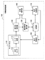
図2は、本発明の一実施形態に係る情報処理装置100の機能構成例を示す図である。図2に示すように、情報処理装置100は、タッチパネル(表示パネル)110、検知領域設定部120、操作体検知部130、状態管理部140、表示制御部150、記憶部160、実行処理部170を含んで構成される。
[2. Functional configuration of information processing apparatus 100]
FIG. 2 is a diagram illustrating a functional configuration example of the
タッチパネル110は、表示制御部150から供給される表示データに基づいて、情報処理装置100による情報処理結果を表示し、特に、オブジェクトデータおよび位置データに基づいて、アイコン等のオブジェクトOを表示する。タッチパネル110は、タッチパネル110上に近接し、またはタッチパネル110に接触する操作体Mを検知する。
The
タッチパネル110は、光学センサ112およびリード回路114を含み、光学センサ112は、タッチパネル110へ入射する外部光の強度を検知し、リード回路114は、光学センサ112により検知された外部光の強度を読取り、操作体Mの陰影を検知する。操作体Mの陰影は、操作体Mの形状、タッチパネル110上での位置を表す陰影データとなる。操作体Mがタッチパネル110上に近接し、またはタッチパネル110に接触すると、操作体Mの陰影がタッチパネル110に投影され、投影された陰影がリード回路114により読み取られ、陰影データとして操作体検知部130に供給される。
The
検知領域設定部120は、タッチパネル110上でオブジェクトO毎に検知領域A1、A2を設定する。ここで、検知領域A1は、オブジェクトOの表示領域を含む領域であり、検知領域A2は、検知領域A1を含み検知領域A1より大きな領域である。検知領域設定部120は、記憶部160に格納されているオブジェクトOの位置データ、および所定の設定値に基づいて、オブジェクトOの表示領域を含む検知領域A1、A2をタッチパネル110上で設定する。ここで、設定値は、オブジェクトOの表示領域に応じて検知領域A1、A2の範囲を設定するために用いられる。
The detection
検知領域A1は、詳細は後述するが、オブジェクトOの表示領域を含むようにタッチパネル110に対して水平方向(X−Y方向)で設定される領域を、タッチパネル110に対して垂直上向き方向(Z方向)に延長した領域(空間)として設定される。また、検知領域A2は、検知領域A1(空間)を含み検知領域A1をX−Y、および/またはZ方向にさらに延長した領域(空間)として設定される。
Although the details will be described later, the detection area A <b> 1 is an area set in the horizontal direction (XY direction) with respect to the
操作体検知部130は、リード回路114から供給される陰影データに基づいて操作体Mを検知し、タッチパネル110上に近接する操作体Mの位置を検出する。操作体Mがタッチパネル110上に近接すると、操作体Mの近接距離に応じて操作体Mの陰影がリード回路114により検知され、操作体Mの形状、タッチパネル110上での位置を表す陰影データとして操作体検知部130に供給される。操作体検知部130は、例えば、陰影データを解析処理等し、指、スタイラスの先端部等、操作体Mの特定位置を検出する。操作体Mの特定位置は、操作体位置データとして、状態管理部140に供給される。
The operating
また、詳細は後述するが、検知領域A1および/または検知領域A2の設定は、タッチパネル110上を近接して移動する操作体Mの移動履歴に応じて変更することができる。この場合、操作体検知部130は、タッチパネル110上を移動する操作体Mの移動履歴を保持し、検知領域設定部120は、操作体Mの移動履歴に基づいて、検知領域A1および/または検知領域A2の設定を変更する。
Although details will be described later, the setting of the detection area A1 and / or the detection area A2 can be changed according to the movement history of the operating tool M that moves close to the
状態管理部140は、タッチパネル110上に近接する操作体Mの検知状況に応じて、オブジェクトOの選択状態または非選択状態を表す状態データを変更する。状態管理部140は、各オブジェクトOの検知領域A1、A2の領域設定データを検知領域設定部120から読出し、操作体位置データを操作体検知部130から供給される。状態管理部140は、予め保持しているオブジェクトOの状態データと、領域設定データおよび操作体位置データに基づいて、状態データを変更するオブジェクトOを特定した上で、オブジェクトOの状態データを変更し、オブジェクトIDとともに実行処理部170に供給する。
The
状態管理部140は、非選択状態にあるオブジェクトOの検知領域A1内で操作体Mが検知される場合に、オブジェクトOの状態データを選択状態に変更する。また、状態管理部140は、選択状態にあるオブジェクトOの検知領域A2内で操作体Mが検知されない場合に、オブジェクトOの状態データを非選択状態に変更する。
The
表示制御部150は、タッチパネル110による情報処理結果の表示を制御し、特にオブジェクトOの表示を制御する。表示制御部150は、情報処理結果の表示を制御するために、実行処理部170から供給される処理結果に基づいて、表示データ等をタッチパネル110に供給する。表示制御部150は、特にオブジェクトOの表示を制御するために、記憶部160に格納されているオブジェクトデータおよび位置データをタッチパネル110に供給する。
The
記憶部160は、オブジェクトデータ、位置データ、オブジェクトOに対応する実体データ、および実体データに対応する実行アプリケーションを、オブジェクトOのオブジェクトIDに関連付けて格納している。オブジェクトデータは、例えばオブジェクトOの画像データである。位置データは、タッチパネル110上での表示位置および表示領域を指定するデータであり、オブジェクトOの移動操作が行われる場合には、移動操作に応じて更新される。
The
実体データとは、タッチパネル110に表示されるオブジェクトOが選択操作された場合に実行される所定の処理に対応するデータであり、オブジェクトOに対応する画像データ等である。実行アプリケーションとは、実行データに対する所定の処理を実行するためのプログラムであり、画像データの表示プログラム等である。
The entity data is data corresponding to a predetermined process executed when the object O displayed on the
実行処理部170は、状態管理部140から供給される状態データおよびオブジェクトIDに基づいて、オブジェクトOに対応する所定の処理を実行する。実行処理部170は、例えば、オブジェクトOの状態データが非選択状態から選択状態に変更された場合に、オブジェクトIDに基づいて、オブジェクトOに対応する実体データ、実行アプリケーションを記憶部160から読出し、所定の処理を実行する。実行処理部170は、例えば、画像表示アプリケーションを用いて実体データである画像データを処理し、処理結果を表示制御部150に供給する。
The
なお、情報処理装置100の各構成要素は、汎用的な部材・回路により構成されてもよく、各構成要素の機能に特化したハードウェアにより構成されてもよい。また、各構成要素の機能のうち少なくとも一部は、CPU上で実行されるプログラムにより実現されてもよい。
In addition, each component of the
[3.情報処理装置100の動作方法]
以下では、図3〜図12を参照しながら、情報処理装置100の動作方法について説明する。
[3. Operation method of information processing apparatus 100]
Hereinafter, an operation method of the
図3は、タッチパネル110に表示されるオブジェクトOの一例を示す図である。図3に示すように、タッチパネル110には、ブラウザ起動用アイコンO1、カメラ撮影モード起動用アイコンO2等、各種のオブジェクトOが表示される。ユーザは、タッチパネル110上で操作体Mを移動することで、オブジェクトOの選択または非選択を操作する。オブジェクトOの選択または非選択が操作されると、情報処理装置100は、例えばブラウザ用プログラム、カメラ撮影用プログラムの実行等、オブジェクトOに対応する処理の実行を開始または終了する。
FIG. 3 is a diagram illustrating an example of the object O displayed on the
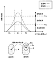
図4は、操作体位置の検出方法を示す図である。情報処理装置100は、操作体Mがタッチパネル110上に近接し、またはタッチパネル110に接触すると、タッチパネル110に投影される操作体Mの陰影を検知することで、操作体Mの近接位置または接触位置を検出する。図4には、タッチパネル110のピクセル座標が横軸に示され、ピクセル毎に検知された操作体Mの陰影が縦軸に示されている。図4に示すように、指、スタイラス等、操作体Mの陰影は、操作体Mの中央部Mmで濃くなり、輪郭部Meで薄くなる。
FIG. 4 is a diagram illustrating a method for detecting the operating body position. When the operating tool M approaches or touches the
操作体Mがタッチパネル110に接触せずに所定の近接距離内でタッチパネル110に近接すると、所定の閾値Thaを超える陰影(実線)が検知されることで、タッチパネル110に近接する操作体Mの中央部Mmが検知される。また、操作体Mがタッチパネル110に接触すると、閾値Thaよりも大きな所定の閾値Thbを超える陰影(点線)が検知されることで、タッチパネル110に接触する操作体Mの中央部Mmおよびタッチパネル110に近接する操作体Mの輪郭部Meが検知される。これにより、タッチパネル110に対してX−Y方向での操作体Mの中央部Mm等の位置から操作体MのX−Y方向位置を検出し、陰影の濃淡から操作体MのZ方向位置を検出することで、操作体位置データを取得することができる。
When the operating tool M approaches the
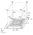
図5は、タッチパネル110上でオブジェクトO毎に設定される検知領域A1、A2を示す模式図である。検知領域A1は、オブジェクトOの表示領域を含む領域であり、検知領域A2は、検知領域A1を含み検知領域A1より大きな領域である。図5に示すように、検知領域A1は、オブジェクトOの表示領域を含むようにタッチパネル110に対して水平方向(X−Y方向)で設定される領域Axy1を、タッチパネル110に対してタッチパネル110から垂直方向(Z方向)に延長した領域(空間)として設定される。また、検知領域A2は、検知領域A1を含み検知領域A1よりもX−Y方向で外側に拡がる領域Axy2を、検知領域A1よりもZ方向にさらに延長した領域(空間)として設定される。
FIG. 5 is a schematic diagram showing detection areas A <b> 1 and A <b> 2 set for each object O on the
なお、タッチパネル110に対して水平方向および垂直方向で検知領域(空間)A1、A2を設定する代わりに、水平方向のみで検知領域A1、A2を設定してもよい。この場合、タッチパネル110に対して所定の垂直距離内に位置する操作体Mが、検知領域A1の内部または外部、A2の内部または外部で検知される。
Instead of setting the detection areas (spaces) A1 and A2 in the horizontal direction and the vertical direction with respect to the
オブジェクトO毎に設定された検知領域A1、A2は、領域設定データにより特定される。例えば、検知領域A1、A2が四角柱状の領域(空間)としてタッチパネル110上に設定される場合、領域設定データは、四角柱状の領域の各頂点を指定するデータとなる。図5に示す例では、検知領域A1は、タッチパネル110上の位置P11〜P18を指定するデータにより特定され、検知領域A2は、タッチパネル110上の位置P21〜P28を指定するデータにより特定される。
The detection areas A1 and A2 set for each object O are specified by the area setting data. For example, when the detection areas A1 and A2 are set on the
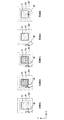
図6は、タッチパネル110に対してX−Y方向での操作体Mの位置に応じて、オブジェクトOの状態が遷移する様子を示す模式図である。なお、図6〜図9については、特に断らない限り、タッチパネル110に対してZ方向で、操作体Mがタッチパネル110に近接して(例えば、図4に示した閾値Thaを超える操作体Mの陰影が検知される距離内)で移動する場合を前提として説明する。
FIG. 6 is a schematic diagram illustrating a state in which the state of the object O transitions according to the position of the operating tool M in the XY direction with respect to the
状態6Aにおいて、検知領域設定部120は、オブジェクトOについて検知領域A1、A2の領域設定データを設定する。状態管理部140は、オブジェクトOの状態データを非選択状態に設定している。操作体検知部130は、検知領域A1外で操作体Mを検知し、操作体位置データを状態管理部140に供給する。状態管理部140は、領域設定データを検知領域設定部120から読出し、領域設定データおよび操作体位置データに基づいて、オブジェクトOの状態データを非選択状態に維持する。
In the state 6A, the detection
状態6Bにおいて、検知領域A1内で操作体Mが検知されると、状態管理部140は、オブジェクトOの状態データを非選択状態から選択状態に変更する。状態6Cにおいて、検知領域A1外かつ検知領域A2内で操作体Mが検知されると、状態管理部140は、オブジェクトOの状態データを選択状態に維持する。状態6Dにおいて、検知領域A2外で操作体Mが検知されると、状態管理部140は、オブジェクトOの状態データを選択状態から非選択状態に変更する。なお、状態6Eにおいて、状態6Aから状態6Dへの遷移途中で、タッチパネル110に対してZ方向で所定の距離内で操作体Mが検知されなくなると、状態管理部140は、オブジェクトOの状態データを非選択状態に維持し、または選択状態から非選択状態に変更する。
When the operating tool M is detected in the detection area A1 in the state 6B, the
状態管理部140は、オブジェクトOの状態データを変更すると、状態データの変更をオブジェクトIDとともに実行処理部170に通知し、実行処理部170は、状態データに応じて、オブジェクトOに対応する所定の処理の実行を開始または終了する。
When the
図7は、タッチパネル110に対してX−Y方向で移動する操作体Mの位置に応じて、オブジェクトOの状態が遷移する様子を示す模式図である。
FIG. 7 is a schematic diagram illustrating a state in which the state of the object O changes according to the position of the operating tool M that moves in the XY direction with respect to the
状態7Aにおける処理は、図6に示した状態6Aにおける処理と同様である。状態7Bにおいて、検知領域A1外から検知領域A1内へ移動した操作体Mが検知されると、状態管理部140は、オブジェクトOの状態データを非選択状態から選択状態に変更する。状態7Cにおいて、検知領域A1内から検知領域A1外かつ検知領域A2内へ移動した操作体Mが検知されると、状態管理部140は、オブジェクトOの状態データを選択状態に維持する。状態7Dにおいて、検知領域A1外かつ検知領域A2内から検知領域A2外へ移動した操作体Mが検知されると、状態管理部140は、オブジェクトOの状態データを選択状態から非選択状態に変更する。なお、状態7Eにおける処理は、図6に示した状態6Eにおける処理と同様である。
The process in state 7A is the same as the process in state 6A shown in FIG. When the operating tool M that has moved from outside the detection area A1 into the detection area A1 is detected in the state 7B, the
図8は、タッチパネル110に対してX−Y方向で移動する操作体Mの位置に応じて、隣接するオブジェクトOa、Obの状態が遷移する様子を示す模式図である。
FIG. 8 is a schematic diagram illustrating a state in which the states of the adjacent objects Oa and Ob change according to the position of the operating tool M that moves in the XY direction with respect to the
状態8Aにおいて、検知領域設定部120は、オブジェクトOa、Obについて、検知領域A1a、A2a、A1b、A2bの領域設定データを設定する。状態管理部140は、オブジェクトOa、Obの状態データを非選択状態に設定している。ここで、オブジェクトOaの検知領域A2aには、オブジェクトObの検知領域A1bと重複する重複領域Aoが含まれている。操作体検知部130は、オブジェクトOa、Obの検知領域A1a、A1b外で操作体Mを検知し、操作体位置データを状態管理部140に供給する。状態管理部140は、領域設定データを検知領域設定部120から読出し、領域設定データおよび操作体位置データに基づいて、オブジェクトOa、Obの状態データを非選択状態に維持する。
In the state 8A, the detection
状態8Bにおいて、オブジェクトOaの検知領域A1a内で操作体Mが検知されると、状態管理部140は、オブジェクトOaの状態データを非選択状態から選択状態に変更する。状態8Cにおいて、オブジェクトOaの検知領域A2aに含まれる重複領域Aoで操作体Mが検知されると、状態管理部140は、オブジェクトOaの状態データを選択状態に維持する。
When the operating tool M is detected in the detection area A1a of the object Oa in the state 8B, the
状態8Dにおいて、オブジェクトOaの検知領域A2a外かつオブジェクトObの検知領域A1b内で操作体Mが検知されると、状態管理部140は、オブジェクトOaの状態データを選択状態から非選択状態に変更するとともに、オブジェクトObの状態データを非選択状態から選択状態に変更する。状態8Eにおいて、オブジェクトObの検知領域A1b外かつ検知領域A2b内で操作体Mが検知されると、状態管理部140は、オブジェクトObの状態データを選択状態に維持する。状態8Fにおいて、オブジェクトObの検知領域A2b外で操作体Mが検知されると、状態管理部140は、オブジェクトObの状態データを選択状態から非選択状態に変更する。
When the operating tool M is detected outside the detection area A2a of the object Oa and within the detection area A1b of the object Ob in the state 8D, the
図9は、タッチパネル110に対してX−Y方向で移動する操作体Mの移動履歴に応じて、検知領域A1、A2の設定を変更する方法を示す模式図である。
FIG. 9 is a schematic diagram illustrating a method of changing the settings of the detection areas A1 and A2 in accordance with the movement history of the operating tool M that moves in the XY direction with respect to the
状態9Aにおける処理は、検知領域A2外で操作体Mが検知されている以外は、図6に示した状態6Aにおける処理と同様である。状態9Bにおいて、操作体MがオブジェクトOに対して右方向に移動すると、操作体検知部130は、操作体Mの移動履歴を保持する。検知領域A2外から検知領域A1内へ移動した操作体Mが検知されると、状態管理部140は、オブジェクトOの状態データを非選択状態から選択状態に変更し、状態データの変更を検知領域設定部120に通知する。検知領域設定部120は、操作体検知部130から移動履歴を読出し、オブジェクトOに対して右方向に移動した操作体Mにより、オブジェクトOの状態データが非選択状態から選択状態に変更されたことを確認する。
The process in the state 9A is the same as the process in the state 6A shown in FIG. 6 except that the operating tool M is detected outside the detection area A2. When the operating tool M moves in the right direction with respect to the object O in the state 9B, the operating
そして、状態9Cに示すように、検知領域設定部120は、オブジェクトOに対する操作体Mの接近方向であるオブジェクトOの左側で検知領域A2をオブジェクトOの左側に拡張する。これにより、状態9Dに示すように、操作体Mが左方向へ僅かに移動しても、拡張された検知領域A2’内で操作体Mが検知されている限り、オブジェクトOが非選択状態にされることを防止することができる。
Then, as shown in the state 9C, the detection
状態9Eにおける処理は、オブジェクトOの状態データが選択状態に設定され、検知領域A1内で操作体Mが検知されている以外は、図6に示した状態6Aにおける処理と同様である。状態9Fにおいて、操作体MがオブジェクトOに対して右方向に移動すると、操作体検知部130は、操作体Mの移動履歴を保持する。検知領域A1内から検知領域A2外へ移動した操作体Mが検知されると、状態管理部140は、オブジェクトOの状態データを選択状態から非選択状態に変更する。検知領域設定部120は、操作体Mの移動履歴に基づいて、オブジェクトOに対して右方向に移動した操作体Mにより、オブジェクトOの状態データが選択状態から非選択状態に変更されたことを確認する。
The process in the state 9E is the same as the process in the state 6A shown in FIG. 6 except that the state data of the object O is set to the selected state and the operating tool M is detected in the detection area A1. When the operating tool M moves in the right direction with respect to the object O in the state 9F, the operating
そして、状態9Gに示すように、検知領域設定部120は、オブジェクトOに対する操作体Mの離隔方向であるオブジェクトOの右側で検知領域A1をオブジェクトOの左側に縮小する。これにより、状態9Hに示すように、操作体Mが左方向へ僅かに移動しても、縮小された検知領域A1’外で操作体Mが検知されている限り、オブジェクトOが選択状態にされることを防止することができる。
Then, as shown in the state 9G, the detection
図10は、タッチパネル110に対してZ方向に移動する操作体Mの位置に応じて、オブジェクトOの状態が遷移する様子を示す模式図である。なお、図10〜図12については、特に断らない限り、タッチパネル110に対してX−Y方向で、操作体MがオブジェクトOの検知領域A1、A2内で移動する場合を前提として説明する。
FIG. 10 is a schematic diagram illustrating a state in which the state of the object O transitions according to the position of the operating tool M that moves in the Z direction with respect to the
状態10Aにおいて、検知領域設定部120は、オブジェクトOについて検知領域A1、A2の領域設定データを設定する。状態管理部140は、オブジェクトOの状態データを非選択状態に設定している。操作体検知部130は、オブジェクトOの検知領域A1外で操作体Mを検知し、操作体位置データを状態管理部140に供給する。状態管理部140は、領域設定データを検知領域設定部120から読出し、領域設定データおよび操作体位置データに基づいて、オブジェクトOの状態データを非選択状態に維持する。
In the state 10A, the detection
状態10Bにおいて、検知領域A1内で操作体Mが検知されると、状態管理部140は、オブジェクトOの状態データを非選択状態から選択状態に変更する。状態10Cにおいて、検知領域A1外かつ検知領域A2内で操作体Mが検知されると、状態管理部140は、オブジェクトOの状態データを選択状態に維持する。状態10Dにおいて、検知領域A2外で操作体Mが検知されると、状態管理部140は、オブジェクトOの状態データを選択状態から非選択状態に変更する。なお、状態10Eにおいて、状態10Aから状態10Dへの遷移途中で、タッチパネル110に対してX−Y方向で、オブジェクトOの検知領域A1、A2内で操作体Mが検知されなくなると、状態管理部140は、オブジェクトOの状態データを非選択状態に維持し、または選択状態から非選択状態に変更する。
When the operating tool M is detected in the detection area A1 in the state 10B, the
図11は、タッチパネル110に対してZ方向に移動する操作体Mの移動履歴に応じて、検知領域A1、A2の設定を変更する方法を示す模式図である。
FIG. 11 is a schematic diagram illustrating a method of changing the settings of the detection areas A1 and A2 according to the movement history of the operating tool M that moves in the Z direction with respect to the
状態11Aにおける処理は、検知領域A2外で操作体Mが検知されている以外は、図10に示した状態10Aにおける処理と同様である。状態11Bにおいて、タッチパネル110に対してZ方向で操作体Mがタッチパネル110に近接する方向に移動すると、操作体検知部130は、操作体Mの移動履歴を保持する。検知領域A2外から検知領域A1内へ移動した操作体Mが検知されると、状態管理部140は、オブジェクトOの状態データを非選択状態から選択状態に変更し、状態データの変更を検知領域設定部120に通知する。検知領域設定部120は、操作体検知部130から移動履歴を読出し、タッチパネル110に近接する方向に移動した操作体Mにより、オブジェクトOの状態データが非選択状態から選択状態に変更されたことを確認する。
The process in the state 11A is the same as the process in the state 10A illustrated in FIG. 10 except that the operating tool M is detected outside the detection area A2. In the state 11B, when the operating tool M moves in the Z direction with respect to the
そして、状態11Cに示すように、検知領域設定部120は、検知領域A2をタッチパネル110の上方に拡張する。これにより、状態11Dに示すように、操作体Mが僅かに上方向へ移動しても、拡張された検知領域A2’内で操作体Mが検知されている限り、オブジェクトOが非選択状態にされることを防止することができる。
Then, as shown in the state 11C, the detection
状態11Eにおける処理は、オブジェクトOの状態データが選択状態に設定され、検知領域A1内で操作体Mが検知されている以外は、図10に示した状態10Aにおける処理と同様である。状態11Fにおいて、タッチパネル110に対してZ方向で操作体Mがタッチパネル110から離隔する方向に移動すると、操作体検知部130は、操作体Mの移動履歴を保持する。検知領域A1内から検知領域A2外へ移動した操作体Mが検知されると、状態管理部140は、オブジェクトOの状態データを選択状態から非選択状態に変更する。検知領域設定部120は、操作体Mの移動履歴に基づいて、タッチパネル110から離隔する方向に移動した操作体Mにより、オブジェクトOの状態データが選択状態から非選択状態に変更されたことを確認する。
The process in the state 11E is the same as the process in the state 10A shown in FIG. 10 except that the state data of the object O is set to the selected state and the operating tool M is detected in the detection area A1. When the operating tool M moves in the Z direction with respect to the
そして、状態11Gに示すように、検知領域設定部120は、検知領域A1をタッチパネル110の下方に縮小する。これにより、状態11Hに示すように、操作体Mが僅かに下方向へ移動しても、縮小された検知領域A1’内で操作体Mが検知されない限り、オブジェクトOが選択状態にされることを防止することができる。
Then, as shown in the state 11G, the detection
図12A、12Bは、タッチパネル110に対してX−Y、Z方向に移動する操作体Mの位置に応じて、オブジェクトOの状態が遷移する様子を示す図である。
12A and 12B are diagrams illustrating a state in which the state of the object O changes according to the position of the operating tool M that moves in the XY and Z directions with respect to the
状態12Aにおける処理は、図10に示した状態10Aにおける処理と同様である。ここで、操作体検知部130は、X−Y、Z方向で検知領域A1外で操作体Mを検知している。状態12Bにおいて、X−Y方向で検知領域A1内、およびZ方向において検知領域A1外で操作体Mが検知されると、状態管理部140は、オブジェクトOの状態データを非選択状態に維持する。なお、X−Y方向で検知領域A1外、およびZ方向で検知領域A1内で操作体Mが検知される場合も同様である。
The process in the state 12A is the same as the process in the state 10A shown in FIG. Here, the operating
状態12Cにおいて、X−Y、Z方向で検知領域A1内で操作体Mが検知されると、状態管理部140は、オブジェクトOの状態データを非選択状態から選択状態に変更する。状態12Dにおいて、X−Y方向で検知領域A1外かつ検知領域A2内およびZ方向で検知領域A1内で操作体Mが検知されると、状態管理部140は、オブジェクトOの状態データを選択状態に維持する。なお、X−Y方向で検知領域A1内およびZ方向で検知領域A1外かつ検知領域A2内で操作体Mが検知される場合も同様である。状態12Eにおいて、X−Y方向およびZ方向で検知領域A1外かつ検知領域A2内で操作体Mが検知されると、状態管理部140は、オブジェクトOの状態データを選択状態に維持する。
In the state 12C, when the operating tool M is detected in the detection area A1 in the XY and Z directions, the
状態12Fにおいて、X−Y方向で検知領域A2外、およびZ方向で検知領域A1外かつ検知領域A2内で操作体Mが検知されると、状態管理部140は、オブジェクトOの状態データを選択状態から非選択状態に変更する。なお、X−Y方向で検知領域A1外かつ検知領域A2内、およびZ方向で検知領域A2外で操作体Mが検知される場合も同様である。状態12Gにおいて、X−Y方向およびX方向で検知領域A2外で操作体Mが検知されると、状態管理部140は、オブジェクトOの状態データを非選択状態に維持する。
When the operating tool M is detected outside the detection area A2 in the XY direction and outside the detection area A1 and within the detection area A2 in the Z direction in the state 12F, the
[4.情報処理装置100のハードウェア構成]
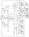
図13は、情報処理装置100のハードウェア構成例を示すブロック図である。
[4. Hardware configuration of information processing apparatus 100]
FIG. 13 is a block diagram illustrating a hardware configuration example of the
情報処理装置100は、主に、CPU901、ROM903、RAM905、ホストバス907、ブリッジ911、外部バス913、インタフェース915、入力装置917、出力装置919、ストレージ装置921、ドライブ923、接続ポート925、通信装置927を含んで構成される。
The
CPU901は、演算処理装置および制御装置として機能し、ROM903、RAM905、ストレージ装置919、またはリムーバブル記録媒体927に記録された各種プログラムに従って、情報処理装置100の動作を少なくとも部分的に制御する。ROM903は、CPU901が用いるプログラムやパラメータ等を記憶する。RAM905は、CPU901が実行するプログラム、プログラム実行時のパラメータ等を一時記憶する。CPU901、ROM903、RAM905は、ホストバス907により互いに接続される。ホストバス907は、ブリッジ909を介して外部バス911に接続される。
The
入力装置915は、例えば、マウス、キーボード、タッチパネル110、ボタン、スイッチ等、ユーザが操作可能な操作手段である。また、入力装置915は、例えば、赤外線等の電波を用いた遠隔操作手段でもよく、情報処理装置100の操作に対応した携帯電話機、PDA等の外部機器929でもよい。入力装置915は、例えば上記の操作手段を用いてユーザにより入力された操作情報に基づいて入力信号を生成し、CPU901に出力する入力制御回路等を含んで構成される。情報処理装置100のユーザは、入力装置915の操作を介して、情報処理装置100に対して各種のデータを入力し、処理動作を指示する。
The
出力装置917は、例えば、CRTディスプレイ、液晶ディスプレイ、ランプ等の表示装置、スピーカ、ヘッドフォン等の音声出力装置、プリンタ、携帯電話機、ファクシミリ等、取得された情報をユーザに対して視覚的または聴覚的に通知可能な装置を含んで構成される。出力装置917は、情報処理装置100の処理結果を出力する。例えば、表示装置は、情報処理装置100による処理結果を、テキスト情報またはイメージ情報として表示し、音声出力装置は、再生された音声データ、音響データ等のオーディオ信号をアナログ信号に変換して出力する。
The
ストレージ装置919は、データ格納用の装置であり、例えば、HDD等の磁気記憶デバイス、半導体記憶デバイス、光記憶デバイス、または光磁気記憶デバイス等を含む。ストレージ装置919は、CPU901が実行するプログラム、各種データ、外部から取得された各種データ等を格納する。
The
ドライブ921は、記録媒体用リーダライタであり、情報処理装置100に内蔵または外付けされる。ドライブ921は、装着される磁気ディスク、光ディスク、光磁気ディスク、または半導体メモリ等のリムーバブル記録媒体927に対して、記録済みデータを読出してRAM905に出力し、記録対象のデータを書き込む。
The
接続ポート923は、例えば、USBポート、SCSIポート、RS232Cポート等、外部機器929を情報処理装置100に直接接続するためのポートである。情報処理装置100は、接続ポート923に接続された外部機器929に対して、接続ポート923を介してデータを取得し、データを提供する。
The
通信装置925は、通信網Nに接続するための通信デバイス等から構成される通信インタフェース913である。通信装置925は、例えば、有線または無線LAN、WUSB用の通信カード、ADSL用のルータ、通信用モデム等である。通信装置925は、例えばインターネットや他の通信機器との間で、所定のプロトコルに則して信号等を送受信する。通信装置925に接続される通信網Nは、有線または無線により接続されたネットワーク等により構成され。例えば、インターネット、家庭内LAN、赤外線通信、ラジオ波通信、または衛星通信等でもよい。
The
以上、本発明の実施形態に係る情報処理装置100の機能を実現するためのハードウェア構成の一例について説明した。なお、上記ハードウェアの各構成要素は、汎用的なデバイスを用いて構成されてもよく、各構成要素の機能の特化したデバイスを用いて構成されてもよい。
Heretofore, an example of the hardware configuration for realizing the functions of the
[5.まとめ]
以上説明したように、本実施形態に係る情報処理装置100によれば、非選択状態にあるオブジェクトOは、検知領域A1内で操作体Mが検知されるまで選択状態にならず、選択状態にあるオブジェクトOは、検知領域A1内で操作体Mが検知されなくても検知領域A2内で操作体Mが検知されている限り非選択状態にならない。これにより、選択対象でないオブジェクトOが誤って選択状態にされ難くなるとともに、選択対象であるオブジェクトOが誤って非選択状態にされ難くなる。よって、操作体Mの僅かな動作に伴う誤操作の発生が防止されることで、タッチパネル110の操作性を向上させることができる。
[5. Summary]
As described above, according to the
以上、添付図面を参照しながら本発明の好適な実施形態について説明したが、本発明は係る例に限定されない。当業者であれば、特許請求の範囲に記載された技術的思想の範疇内において、各種の変更例または修正例に想到し得ることは明らかであり、それらについても当然に本発明の技術的範囲に属するものと了解される。 As mentioned above, although preferred embodiment of this invention was described referring an accompanying drawing, this invention is not limited to the example which concerns. It is obvious for those skilled in the art that various changes or modifications can be conceived within the scope of the technical idea described in the claims. It is understood that it belongs to.
100 情報処理装置
110 タッチパネル(表示パネル)
120 検知領域設定部
130 操作体検知部
140 状態管理部
100
120 Detection
Claims (8)
前記オブジェクトの表示領域を含む第1の検知領域、および前記第1の検知領域を含み前記第1の検知領域より大きな第2の検知領域を、前記表示パネル上で前記オブジェクト毎に設定する検知領域設定部と、
前記表示パネル上に近接する操作体を検知する操作体検知部と、
非選択状態にある前記オブジェクトの前記第1の検知領域内で前記操作体が検知される場合に、前記オブジェクトを選択状態にし、選択状態にある前記オブジェクトの前記第2の検知領域内で前記操作体が検知されない場合に、前記オブジェクトを非選択状態にする状態管理部と、
を備え、
前記操作体検知部は、前記表示パネル上に近接して移動する前記操作体の移動履歴を検知し、
前記検知領域設定部は、前記操作体の移動履歴に応じて、前記第1の検知領域および/または前記第2の検知領域を前記表示パネル上で前記オブジェクト毎に変更する情報処理装置。 A display panel on which one or more objects in a selected state or a non-selected state are displayed;
A detection area for setting a first detection area including the display area of the object and a second detection area including the first detection area and larger than the first detection area for each object on the display panel A setting section;
An operating tool detection unit for detecting an operating tool close to the display panel;
When the operation body is detected in the first detection area of the object in the non-selected state, the object is selected, and the operation is performed in the second detection area of the object in the selected state. A state management unit for deselecting the object when no body is detected;
Equipped with a,
The operating tool detection unit detects a movement history of the operating tool that moves close to the display panel,
The information processing apparatus, wherein the detection area setting unit changes the first detection area and / or the second detection area for each object on the display panel in accordance with a movement history of the operating body .
前記状態管理部は、非選択状態にある前記オブジェクトの前記第1の検知領域内で、前記表示パネルから所定の垂直距離内に近接する前記操作体が検知された場合に、前記オブジェクトを選択状態にし、選択状態にある前記オブジェクトの前記第2の検知領域内で、前記表示パネルから所定の垂直距離内に近接する前記操作体が検知されない場合に、前記オブジェクトを非選択状態にする、請求項1に記載の情報処理装置。 The detection area setting unit includes a first detection area including a display area of the object in a horizontal direction with respect to the display panel, and a first detection area including the first detection area in the horizontal direction with respect to the display panel. A second detection area extending outside the detection area is set for each object on the display panel;
The state management unit selects the object in the first detection area of the object that is in the non-selected state when the operating body that is close to the display panel within a predetermined vertical distance is detected. The object is set in a non-selected state when the operating body that is close to the display panel within a predetermined vertical distance is not detected within the second detection area of the object in the selected state. The information processing apparatus according to 1.
前記状態管理部は、非選択状態にある前記オブジェクトの前記第1の検知領域内で前記操作体が検知された場合に、前記オブジェクトを選択状態にし、選択状態にある前記オブジェクトの前記第2の検知領域内で前記操作体が検知されない場合に、前記オブジェクトを非選択状態にする、請求項1に記載の情報処理装置。 The detection area setting unit includes a first detection area including a display area of the object in a horizontal direction and a vertical direction with respect to the display panel, and a horizontal direction with respect to the display panel including the first detection area. A second detection area extending outward from the first detection area and extending away from the display panel from the first detection area in a direction perpendicular to the display panel is formed on the display panel. Set for each object,
The state management unit sets the object to a selected state when the operating body is detected within the first detection area of the object in a non-selected state, and sets the second object of the object in a selected state. The information processing apparatus according to claim 1, wherein the object is set to a non-selected state when the operation body is not detected in a detection area.
前記オブジェクトの表示領域を含む第1の検知領域、および前記第1の検知領域を含み前記第1の検知領域より大きな第2の検知領域を、前記表示パネルで前記オブジェクト毎に設定し、
前記表示パネル上に近接する操作体を検知し、
非選択状態にある前記オブジェクトの前記第1の検知領域内で前記操作体が検知される場合に、前記オブジェクトを選択状態にし、選択状態にある前記オブジェクトの前記第2の検知領域内で前記操作体が検知されない場合に、前記オブジェクトを非選択状態にし、
さらに、前記表示パネル上に近接して移動する前記操作体の移動履歴を検知し、前記操作体の移動履歴に応じて、前記第1の検知領域および/または前記第2の検知領域を前記表示パネル上で前記オブジェクト毎に設定変更する情報処理方法。 Display one or more objects in the selected or unselected state on the display panel,
A first detection area including the display area of the object, and a second detection area including the first detection area and larger than the first detection area are set for each object on the display panel,
Detecting an operating body close to the display panel,
When the operation body is detected in the first detection area of the object in the non-selected state, the object is selected, and the operation is performed in the second detection area of the object in the selected state. If no body is detected, deselect the object ,
Further, a movement history of the operating body that moves close to the display panel is detected, and the first detection area and / or the second detection area is displayed according to the movement history of the operating body. An information processing method for changing settings for each object on a panel .
前記オブジェクトの表示領域を含む第1の検知領域、および前記第1の検知領域を含み前記第1の検知領域より大きな第2の検知領域を、前記表示パネルで前記オブジェクト毎に設定し、
前記表示パネル上に近接する操作体を検知し、
非選択状態にある前記オブジェクトの前記第1の検知領域内で前記操作体が検知される場合に、前記オブジェクトを選択状態にし、選択状態にある前記オブジェクトの前記第2の検知領域内で前記操作体が検知されない場合に、前記オブジェクトを非選択状態にし、
さらに、前記表示パネル上に近接して移動する前記操作体の移動履歴を検知し、前記操作体の移動履歴に応じて、前記第1の検知領域および/または前記第2の検知領域を前記表示パネル上で前記オブジェクト毎に設定変更する情報処理方法をコンピュータに実行させるためのプログラム。 Display one or more objects in the selected or unselected state on the display panel,
A first detection area including the display area of the object, and a second detection area including the first detection area and larger than the first detection area are set for each object on the display panel,
Detecting an operating body close to the display panel,
When the operation body is detected in the first detection area of the object in the non-selected state, the object is selected, and the operation is performed in the second detection area of the object in the selected state. If no body is detected, deselect the object ,
Further, a movement history of the operating body that moves close to the display panel is detected, and the first detection area and / or the second detection area is displayed according to the movement history of the operating body. A program for causing a computer to execute an information processing method for changing a setting for each object on a panel .
Priority Applications (4)
| Application Number | Priority Date | Filing Date | Title |
|---|---|---|---|
| JP2009068620A JP5287403B2 (en) | 2009-03-19 | 2009-03-19 | Information processing apparatus, information processing method, and program |
| EP10250093.1A EP2230586A3 (en) | 2009-03-19 | 2010-01-21 | Information processing apparatus, information processing method, and program |
| US12/719,617 US9811187B2 (en) | 2009-03-19 | 2010-03-08 | Information processing apparatus, information processing method, and program |
| CN2010101341132A CN101840284B (en) | 2009-03-19 | 2010-03-12 | Information processing apparatus, information processing method |
Applications Claiming Priority (1)
| Application Number | Priority Date | Filing Date | Title |
|---|---|---|---|
| JP2009068620A JP5287403B2 (en) | 2009-03-19 | 2009-03-19 | Information processing apparatus, information processing method, and program |
Publications (3)
| Publication Number | Publication Date |
|---|---|
| JP2010224663A JP2010224663A (en) | 2010-10-07 |
| JP2010224663A5 JP2010224663A5 (en) | 2012-04-05 |
| JP5287403B2 true JP5287403B2 (en) | 2013-09-11 |
Family
ID=42105862
Family Applications (1)
| Application Number | Title | Priority Date | Filing Date |
|---|---|---|---|
| JP2009068620A Expired - Fee Related JP5287403B2 (en) | 2009-03-19 | 2009-03-19 | Information processing apparatus, information processing method, and program |
Country Status (4)
| Country | Link |
|---|---|
| US (1) | US9811187B2 (en) |
| EP (1) | EP2230586A3 (en) |
| JP (1) | JP5287403B2 (en) |
| CN (1) | CN101840284B (en) |
Families Citing this family (15)
| Publication number | Priority date | Publication date | Assignee | Title |
|---|---|---|---|---|
| US8730309B2 (en) | 2010-02-23 | 2014-05-20 | Microsoft Corporation | Projectors and depth cameras for deviceless augmented reality and interaction |
| JP5561089B2 (en) * | 2010-10-15 | 2014-07-30 | ソニー株式会社 | Information processing apparatus, information processing method, and computer program |
| JP2012133729A (en) * | 2010-12-24 | 2012-07-12 | Sony Corp | Information processing device, information processing method and program |
| EP2523129B1 (en) * | 2011-05-11 | 2020-07-01 | Dassault Systèmes | Selection of a manipulator of an object among a plurality of manipulators |
| US20130057515A1 (en) * | 2011-09-07 | 2013-03-07 | Microsoft Corporation | Depth camera as a touch sensor |
| KR101354234B1 (en) * | 2011-12-05 | 2014-01-22 | (주)이스트소프트 | Method for providing application in device of touch-input |
| JP2015084124A (en) * | 2012-02-06 | 2015-04-30 | パナソニック株式会社 | Information processing device |
| JP5620947B2 (en) * | 2012-06-27 | 2014-11-05 | キヤノン株式会社 | Electronic device, control method therefor, program, and storage medium |
| US10261612B2 (en) * | 2013-02-22 | 2019-04-16 | Samsung Electronics Co., Ltd. | Apparatus and method for recognizing proximity motion using sensors |
| JP5820414B2 (en) * | 2013-03-19 | 2015-11-24 | 株式会社Nttドコモ | Information processing apparatus and information processing method |
| JP2015022496A (en) * | 2013-07-18 | 2015-02-02 | 富士通株式会社 | Control program, control method, and control device |
| JP6181192B2 (en) * | 2013-09-26 | 2017-08-16 | テルモ株式会社 | Information processing apparatus and program |
| KR20160063812A (en) * | 2014-11-27 | 2016-06-07 | 삼성전자주식회사 | Method for configuring screen, electronic apparatus and storage medium |
| JP6943562B2 (en) * | 2016-11-25 | 2021-10-06 | トヨタ自動車株式会社 | Display control device |
| JP7190820B2 (en) * | 2018-04-02 | 2022-12-16 | パナソニックホールディングス株式会社 | Intrusion detection system and intrusion detection method |
Family Cites Families (11)
| Publication number | Priority date | Publication date | Assignee | Title |
|---|---|---|---|---|
| JPH073651B2 (en) * | 1987-03-16 | 1995-01-18 | 富士通株式会社 | Touch input detection method |
| JP3123558B2 (en) * | 1991-05-09 | 2001-01-15 | ソニー株式会社 | Information input processing device and method |
| JP3029905B2 (en) * | 1991-12-17 | 2000-04-10 | シャープ株式会社 | Data input device |
| FI112119B (en) * | 2002-06-25 | 2003-10-31 | Nokia Corp | Touch screen control command interpreting method for electronic device e.g. mobile station, involves interpreting contact area larger than area before touch, as same area when area has been touched for release of touch |
| JP4723799B2 (en) | 2003-07-08 | 2011-07-13 | 株式会社ソニー・コンピュータエンタテインメント | Control system and control method |
| JP2005215749A (en) * | 2004-01-27 | 2005-08-11 | Nec Corp | Selection system and selection method of operating element |
| JP4148187B2 (en) * | 2004-06-03 | 2008-09-10 | ソニー株式会社 | Portable electronic device, input operation control method and program thereof |
| JP4479962B2 (en) * | 2005-02-25 | 2010-06-09 | ソニー エリクソン モバイル コミュニケーションズ, エービー | Input processing program, portable terminal device, and input processing method |
| JP4819467B2 (en) * | 2005-10-04 | 2011-11-24 | 任天堂株式会社 | Object movement control program and information processing apparatus |
| US8284165B2 (en) * | 2006-10-13 | 2012-10-09 | Sony Corporation | Information display apparatus with proximity detection performance and information display method using the same |
| JP4794004B2 (en) | 2007-09-14 | 2011-10-12 | 東洋ゴム工業株式会社 | Anti-vibration bush |
-
2009
- 2009-03-19 JP JP2009068620A patent/JP5287403B2/en not_active Expired - Fee Related
-
2010
- 2010-01-21 EP EP10250093.1A patent/EP2230586A3/en not_active Withdrawn
- 2010-03-08 US US12/719,617 patent/US9811187B2/en active Active
- 2010-03-12 CN CN2010101341132A patent/CN101840284B/en not_active Expired - Fee Related
Also Published As
| Publication number | Publication date |
|---|---|
| EP2230586A3 (en) | 2014-09-10 |
| CN101840284A (en) | 2010-09-22 |
| CN101840284B (en) | 2012-10-10 |
| EP2230586A2 (en) | 2010-09-22 |
| US9811187B2 (en) | 2017-11-07 |
| US20100238107A1 (en) | 2010-09-23 |
| JP2010224663A (en) | 2010-10-07 |
Similar Documents
| Publication | Publication Date | Title |
|---|---|---|
| JP5287403B2 (en) | Information processing apparatus, information processing method, and program | |
| JP2010224663A5 (en) | ||
| JP5402322B2 (en) | Information processing apparatus and information processing method | |
| US8836649B2 (en) | Information processing apparatus, information processing method, and program | |
| JP4818427B2 (en) | Information processing apparatus and screen selection method | |
| JP5703873B2 (en) | Information processing apparatus, information processing method, and program | |
| JP4900361B2 (en) | Image processing apparatus, image processing method, and program | |
| JP2010086230A (en) | Information processing apparatus, information processing method and program | |
| JP2010176332A (en) | Information processing apparatus, information processing method, and program | |
| JP6123879B2 (en) | Display device, display method, program thereof, and terminal device | |
| JPWO2010095255A1 (en) | Information processing apparatus, display control method, and display control program | |
| US9927914B2 (en) | Digital device and control method thereof | |
| JP2005301668A (en) | Information processor and information processing program | |
| WO2010029619A1 (en) | Portable terminal | |
| US8819584B2 (en) | Information processing apparatus and image display method | |
| JP5232033B2 (en) | Information processing apparatus, information operation method, and program | |
| JP3809424B2 (en) | Selection area control device, selection area control method, and selection area control program | |
| US20140253479A1 (en) | Display device and display method | |
| US20160179352A1 (en) | Information processing apparatus, computer-readable recording medium storing display control program, and display control method | |
| US8972889B2 (en) | Display processing apparatus and display processing method | |
| US20170228149A1 (en) | Information processing apparatus and information processing method | |
| JP4977162B2 (en) | Information processing apparatus, command execution control method, and command execution control program | |
| WO2018159414A1 (en) | Terminal device and operation control program | |
| US10963137B2 (en) | Information display apparatus and non-transitory recording medium storing program for controlling information display apparatus | |
| US20120151409A1 (en) | Electronic Apparatus and Display Control Method |
Legal Events
| Date | Code | Title | Description |
|---|---|---|---|
| A521 | Written amendment |
Free format text: JAPANESE INTERMEDIATE CODE: A523 Effective date: 20120222 |
|
| A621 | Written request for application examination |
Free format text: JAPANESE INTERMEDIATE CODE: A621 Effective date: 20120222 |
|
| A977 | Report on retrieval |
Free format text: JAPANESE INTERMEDIATE CODE: A971007 Effective date: 20121213 |
|
| A131 | Notification of reasons for refusal |
Free format text: JAPANESE INTERMEDIATE CODE: A131 Effective date: 20121218 |
|
| A521 | Written amendment |
Free format text: JAPANESE INTERMEDIATE CODE: A523 Effective date: 20130123 |
|
| TRDD | Decision of grant or rejection written | ||
| A01 | Written decision to grant a patent or to grant a registration (utility model) |
Free format text: JAPANESE INTERMEDIATE CODE: A01 Effective date: 20130507 |
|
| A61 | First payment of annual fees (during grant procedure) |
Free format text: JAPANESE INTERMEDIATE CODE: A61 Effective date: 20130520 |
|
| LAPS | Cancellation because of no payment of annual fees |