JP2010176332A - Information processing apparatus, information processing method, and program - Google Patents
Information processing apparatus, information processing method, and program Download PDFInfo
- Publication number
- JP2010176332A JP2010176332A JP2009017204A JP2009017204A JP2010176332A JP 2010176332 A JP2010176332 A JP 2010176332A JP 2009017204 A JP2009017204 A JP 2009017204A JP 2009017204 A JP2009017204 A JP 2009017204A JP 2010176332 A JP2010176332 A JP 2010176332A
- Authority
- JP
- Japan
- Prior art keywords
- display
- information processing
- processing apparatus
- moving
- movement
- Prior art date
- Legal status (The legal status is an assumption and is not a legal conclusion. Google has not performed a legal analysis and makes no representation as to the accuracy of the status listed.)
- Pending
Links
Images


Classifications
-
- G—PHYSICS
- G06—COMPUTING; CALCULATING OR COUNTING
- G06F—ELECTRIC DIGITAL DATA PROCESSING
- G06F3/00—Input arrangements for transferring data to be processed into a form capable of being handled by the computer; Output arrangements for transferring data from processing unit to output unit, e.g. interface arrangements
- G06F3/01—Input arrangements or combined input and output arrangements for interaction between user and computer
- G06F3/048—Interaction techniques based on graphical user interfaces [GUI]
- G06F3/0487—Interaction techniques based on graphical user interfaces [GUI] using specific features provided by the input device, e.g. functions controlled by the rotation of a mouse with dual sensing arrangements, or of the nature of the input device, e.g. tap gestures based on pressure sensed by a digitiser
- G06F3/0488—Interaction techniques based on graphical user interfaces [GUI] using specific features provided by the input device, e.g. functions controlled by the rotation of a mouse with dual sensing arrangements, or of the nature of the input device, e.g. tap gestures based on pressure sensed by a digitiser using a touch-screen or digitiser, e.g. input of commands through traced gestures
- G06F3/04883—Interaction techniques based on graphical user interfaces [GUI] using specific features provided by the input device, e.g. functions controlled by the rotation of a mouse with dual sensing arrangements, or of the nature of the input device, e.g. tap gestures based on pressure sensed by a digitiser using a touch-screen or digitiser, e.g. input of commands through traced gestures for inputting data by handwriting, e.g. gesture or text
-
- G—PHYSICS
- G06—COMPUTING; CALCULATING OR COUNTING
- G06F—ELECTRIC DIGITAL DATA PROCESSING
- G06F1/00—Details not covered by groups G06F3/00 - G06F13/00 and G06F21/00
- G06F1/16—Constructional details or arrangements
- G06F1/1613—Constructional details or arrangements for portable computers
- G06F1/1633—Constructional details or arrangements of portable computers not specific to the type of enclosures covered by groups G06F1/1615 - G06F1/1626
- G06F1/1637—Details related to the display arrangement, including those related to the mounting of the display in the housing
- G06F1/1643—Details related to the display arrangement, including those related to the mounting of the display in the housing the display being associated to a digitizer, e.g. laptops that can be used as penpads
-
- G—PHYSICS
- G06—COMPUTING; CALCULATING OR COUNTING
- G06F—ELECTRIC DIGITAL DATA PROCESSING
- G06F1/00—Details not covered by groups G06F3/00 - G06F13/00 and G06F21/00
- G06F1/16—Constructional details or arrangements
- G06F1/1613—Constructional details or arrangements for portable computers
- G06F1/1633—Constructional details or arrangements of portable computers not specific to the type of enclosures covered by groups G06F1/1615 - G06F1/1626
- G06F1/1637—Details related to the display arrangement, including those related to the mounting of the display in the housing
- G06F1/1647—Details related to the display arrangement, including those related to the mounting of the display in the housing including at least an additional display
-
- G—PHYSICS
- G06—COMPUTING; CALCULATING OR COUNTING
- G06F—ELECTRIC DIGITAL DATA PROCESSING
- G06F3/00—Input arrangements for transferring data to be processed into a form capable of being handled by the computer; Output arrangements for transferring data from processing unit to output unit, e.g. interface arrangements
- G06F3/01—Input arrangements or combined input and output arrangements for interaction between user and computer
- G06F3/048—Interaction techniques based on graphical user interfaces [GUI]
- G06F3/0484—Interaction techniques based on graphical user interfaces [GUI] for the control of specific functions or operations, e.g. selecting or manipulating an object, an image or a displayed text element, setting a parameter value or selecting a range
- G06F3/0486—Drag-and-drop
Abstract
Description
本発明は、情報処理装置、情報処理方法およびプログラムに関する。 The present invention relates to an information processing apparatus, an information processing method, and a program.
近年、小型の電子機器や自動取引装置には、ユーザが表示画面に直接接触して画面内に表示されたオブジェクトを操作するためのタッチパネルが搭載されていることが多い。タッチパネルを用いることにより、直感的な操作感が実現され、キーボードやキーパッド等の操作に不慣れなユーザでも容易に操作が行えるという利点が得られる。最近の電子機器には、ユーザがタッチパネルを操作することにより、画面内に表示された表示オブジェクトが移動されたり、この移動操作により所定の処理が実行されたりするものもある。 In recent years, small electronic devices and automatic transaction apparatuses are often equipped with a touch panel for a user to directly touch a display screen and operate an object displayed in the screen. By using the touch panel, an intuitive feeling of operation is realized, and an advantage is obtained that even a user unfamiliar with the operation of a keyboard, a keypad, or the like can easily perform the operation. Some recent electronic devices have a display object displayed on the screen moved by a user operating a touch panel, and a predetermined process is executed by the moving operation.
上述のような表示画面が2つ連結された折り畳み式の電子機器の場合、1つの表示画面しか存在しない電子機器に比べ2つの表示画面に多くの情報を表示させることが可能となるため、ユーザの利便性は向上することとなる。しかしながら、2つの表示画面が互いに連結されている部分では、オブジェクトの表示ができない場合が多いため、折り畳み式の電子機器では、このような連結部分に対する対応が重要となる。 In the case of a foldable electronic device in which two display screens are connected as described above, more information can be displayed on two display screens than an electronic device that has only one display screen. The convenience will be improved. However, since there are many cases where an object cannot be displayed in a portion where two display screens are connected to each other, it is important to deal with such a connected portion in a foldable electronic device.
例えば、以下に示す特許文献1では、一方の表示画面から他方の表示画面へと表示オブジェクトの移動を行う際に、移動指示が終了した時点における移動速度が所定の速度以上であった場合に、画面間にまたがる移動を実行する技術が開示されている。また、以下に示す特許文献2では、2つの表示画面の間に位置する連結部分を含め、2つの表示画面を仮想的な1つの表示画面として取り扱うプログラムが開示されている。 For example, in Patent Document 1 shown below, when moving a display object from one display screen to the other display screen, when the movement speed at the time when the movement instruction ends is equal to or higher than a predetermined speed, A technique for performing movement across screens is disclosed. Patent Document 2 shown below discloses a program that handles two display screens as one virtual display screen, including a connection portion positioned between the two display screens.
しかしながら、上記特許文献1に記載の技術では、2つの画面にまたがるオブジェクトの移動を行いたいユーザは、移動指示終了時の移動速度を考慮した操作を行う必要があるため、装置の操作性に問題がある。また、上記特許文献2に記載のプログラムでは、表示オブジェクトに対する移動処理の結果、2つの表示画面の間に位置する連結部分に表示オブジェクトの一部が存在してしまう場合については、考慮していない。 However, in the technique described in Patent Document 1, a user who wants to move an object across two screens needs to perform an operation in consideration of the movement speed at the end of the movement instruction. There is. Further, the program described in Patent Document 2 does not take into consideration the case where a part of the display object exists in the connection portion positioned between the two display screens as a result of the movement process for the display object. .
そこで、本発明は、上記問題に鑑みてなされたものであり、本発明の目的とするところは、特別な操作を行うことなく、一方の表示画面に表示されている表示オブジェクトを他方の表示画面へと容易に移動させることが可能な、情報処理装置、情報処理方法およびプログラムを提供することにある。 Therefore, the present invention has been made in view of the above problems, and an object of the present invention is to display a display object displayed on one display screen without performing a special operation. To provide an information processing apparatus, an information processing method, and a program that can be easily moved.
上記課題を解決するために、本発明のある観点によれば、複数のオブジェクトを表示可能であり、前記オブジェクトが表示されない非表示領域となる連結部を介して互いに連結された第1および第2の表示パネルと、前記表示パネル上に位置する操作体の位置を検出する入力位置検出部と、検出された前記操作体の位置の時間変化に基づいて、前記操作体の移動方向を検知する方向検知部と、前記操作体により選択された前記オブジェクトを前記操作体が描く軌跡に応じて移動させる際の移動位置を算出する移動位置算出部と、算出された移動後の前記オブジェクトの少なくとも一部が前記非表示領域に位置する場合に、当該オブジェクトの表示位置または前記操作体の移動方向に基づいて、前記非表示領域から前記オブジェクトを移動させる表示位置補正部と、を備える情報処理装置が提供される。 In order to solve the above-described problem, according to an aspect of the present invention, a plurality of objects can be displayed, and a first and a second are connected to each other via a connecting portion that is a non-display area where the objects are not displayed. A display panel, an input position detection unit that detects the position of the operating body located on the display panel, and a direction in which the moving direction of the operating body is detected based on a time change of the detected position of the operating body A detection unit; a movement position calculation unit that calculates a movement position when moving the object selected by the operation body according to a trajectory drawn by the operation body; and at least a part of the calculated moved object Is located in the non-display area, the object is moved from the non-display area based on the display position of the object or the moving direction of the operating body. The information processing apparatus is provided comprising, a display position correction unit.
かかる構成によれば、入力位置検出部は、表示パネル上に位置する操作体の位置を検出し、方向検知部は、検出された操作体の位置の時間変化に基づいて、操作体の移動方向を検知する。また、移動位置算出部は、操作体により選択されたオブジェクトを操作体が描く軌跡に応じて移動させる際の移動位置を算出する。また、表示位置補正部は、算出された移動後のオブジェクトの少なくとも一部が非表示領域に位置する場合に、当該オブジェクトの表示位置または操作体の移動方向に基づいて、非表示領域からオブジェクトを移動させる。 According to such a configuration, the input position detection unit detects the position of the operation body located on the display panel, and the direction detection unit detects the movement direction of the operation body based on the time change of the detected position of the operation body. Is detected. In addition, the movement position calculation unit calculates a movement position when moving the object selected by the operation body according to the locus drawn by the operation body. In addition, when at least a part of the calculated moved object is located in the non-display area, the display position correction unit removes the object from the non-display area based on the display position of the object or the moving direction of the operation tool. Move.
前記表示位置補正部は、前記オブジェクトの重心の存在位置に基づいて、前記オブジェクトを前記重心が存在する側の前記表示パネルへと移動させることが好ましい。 Preferably, the display position correction unit moves the object to the display panel on the side where the center of gravity exists based on the position where the center of gravity of the object exists.
前記表示位置補正部は、前記オブジェクトが前記非表示領域に近接している場合に、前記オブジェクトを前記操作体の移動方向側の前記表示パネルへと移動させてもよい。 The display position correction unit may move the object to the display panel on the moving direction side of the operating body when the object is close to the non-display area.
前記表示位置補正部は、一方の前記表示パネルから他方の前記表示パネルへと前記オブジェクトを移動させることでオブジェクトに関連付けられた属性情報が変更となる場合に、前記オブジェクトを前記操作体の移動方向側の前記表示パネルへと移動させてもよい。 The display position correction unit moves the object in the moving direction of the operation body when attribute information associated with the object is changed by moving the object from one display panel to the other display panel. You may move to the said display panel of the side.
また、上記課題を解決するために、本発明の別の観点によれば、複数のオブジェクトが表示可能であり、前記オブジェクトが表示されない非表示領域となる連結部を介して互いに連結された第1および第2の表示パネル上に位置する操作体の位置を検出するステップと、検出された前記操作体の位置の時間変化に基づいて、前記操作体の移動方向を検知するステップと、前記操作体により選択された前記オブジェクトを前記操作体が描く軌跡に応じて移動させる際の移動位置を算出するステップと、算出された移動後の前記オブジェクトの少なくとも一部が前記非表示領域に位置する場合に、当該オブジェクトの表示位置または前記操作体の移動方向に基づいて、前記非表示領域から前記オブジェクトを移動させるステップと、を含む情報処理方法が提供される。 In order to solve the above problem, according to another aspect of the present invention, a plurality of objects can be displayed, and the first objects are connected to each other via a connecting portion that is a non-display area where the objects are not displayed. And a step of detecting a position of the operating body located on the second display panel, a step of detecting a moving direction of the operating body based on a time change of the detected position of the operating body, and the operating body A step of calculating a movement position when moving the object selected in accordance with a trajectory drawn by the operating body, and when at least a part of the calculated object after movement is located in the non-display area And moving the object from the non-display area based on the display position of the object or the moving direction of the operating body. A method is provided.
また、上記課題を解決するために、本発明の更に別の観点によれば、複数のオブジェクトが表示可能であり、前記オブジェクトが表示されない非表示領域となる連結部を介して互いに連結された第1および第2の表示パネルを有するコンピュータに、前記表示パネル上に位置する操作体の位置を検出する入力位置検出機能と、検出された前記操作体の位置の時間変化に基づいて、前記操作体の移動方向を検知する方向検知機能と、前記操作体により選択された前記オブジェクトを前記操作体が描く軌跡に応じて移動させる際の移動位置を算出する移動位置算出機能と、算出された移動後の前記オブジェクトの少なくとも一部が前記非表示領域に位置する場合に、当該オブジェクトの表示位置または前記操作体の移動方向に基づいて、前記非表示領域から前記オブジェクトを移動させる表示位置補正機能と、を実現させるためのプログラムが提供される。 In order to solve the above-described problem, according to still another aspect of the present invention, a plurality of objects can be displayed, and the objects are connected to each other via a connecting portion that is a non-display area where the objects are not displayed. The computer having the first and second display panels has an input position detection function for detecting the position of the operating body positioned on the display panel, and the operating body based on the time change of the detected position of the operating body. A direction detecting function for detecting the moving direction of the object, a moving position calculating function for calculating a moving position when the object selected by the operating body is moved according to a trajectory drawn by the operating body, and a calculated post-movement When at least part of the object is located in the non-display area, the non-display is based on the display position of the object or the moving direction of the operating body. Program for realizing a display position correction function for moving the object from the area is provided.
以上説明したように本発明によれば、移動後のオブジェクトの少なくとも一部が非表示領域に位置する場合に、当該オブジェクトの表示位置または操作体の移動方向に基づいて、非表示領域からオブジェクトを移動させる処理を行う。そのため、ユーザは、特別な操作を行うことなく、一方の表示画面に表示されている表示オブジェクトを他方の表示画面へと容易に移動させることが可能である。 As described above, according to the present invention, when at least a part of the moved object is located in the non-display area, the object is moved from the non-display area based on the display position of the object or the moving direction of the operating tool. Process to move. Therefore, the user can easily move the display object displayed on one display screen to the other display screen without performing a special operation.
以下に添付図面を参照しながら、本発明の好適な実施の形態について詳細に説明する。なお、本明細書及び図面において、実質的に同一の機能構成を有する構成要素については、同一の符号を付することにより重複説明を省略する。 Exemplary embodiments of the present invention will be described below in detail with reference to the accompanying drawings. In addition, in this specification and drawing, about the component which has the substantially same function structure, duplication description is abbreviate | omitted by attaching | subjecting the same code | symbol.
なお、説明は、以下の順序で行うものとする。
(1)目的
(2)第1の実施形態
(2−1)情報処理装置の外観について
(2−2)情報処理装置の構成について
(2−3)情報処理方法について
(3)本発明の各実施形態に係る情報処理装置のハードウェア構成について
(4)まとめ
The description will be made in the following order.
(1) Purpose (2) First embodiment (2-1) Appearance of information processing device (2-2) Configuration of information processing device (2-3) Information processing method (3) Each of the present invention Hardware configuration of information processing apparatus according to embodiment (4) Summary
<目的>
本発明の各実施形態に係る情報処理装置および情報処理方法について説明するに先立ち、図13を参照しながら、2つの表示画面を有する電子機器において生じうる問題点について説明し、本発明の目的とするところについて、説明を行う。
<Purpose>
Prior to describing the information processing apparatus and information processing method according to each embodiment of the present invention, problems that may occur in an electronic device having two display screens will be described with reference to FIG. The place to do is explained.
例えば図13に示したように、2つの表示画面501A,501Bが存在する電子機器において、どちらか一方の表示画面に表示されていたアイコン等のオブジェクト503をユーザによるドラッグ操作等により移動させる場合を考える。この際に、図13に示したように、ユーザ操作によっては、移動後のオブジェクト503の一部が、表示画面501Aと表示画面501Bとの間に位置する連結部505に位置してしまう場合が生じうる。
For example, as shown in FIG. 13, in an electronic device having two display screens 501A and 501B, a case where an
ここで、連結部505の裏にも画素が存在している場合には、図13(a)に示したように、連結部505の裏にオブジェクト503の一部が表示されるものの、連結部505の外装によりオブジェクト503の一部が遮蔽されてしまうこととなる。その結果、ユーザは、オブジェクト503の内容把握が困難となってしまう。
Here, when pixels are also present on the back side of the connecting
また、連結部505の裏に画素が存在していない場合には、図13(b)に示したように、オブジェクトが途中で分断されて表示されることとなる。その結果、ユーザは、オブジェクトの大きさが異なっているように感じてしまう。
If no pixel is present behind the connecting
このように、2つの表示画面が、オブジェクトが表示されない連結部を介して連結されているような電子機器において、オブジェクトの一部が連結部に存在してしまった場合には、1画面だけでオブジェクトを閲覧した場合に比べて見え方に違和感が生じてしまう。そのため、画面間をまたぐオブジェクトの移動処理を実行する際には、ユーザによる特別な操作によらず、連結部にオブジェクトが位置しないようにする技術が必要となる。 In this way, in an electronic device in which two display screens are connected via a connecting part that does not display an object, if a part of the object exists in the connecting part, only one screen is required. Compared to the case of browsing the object, the appearance is uncomfortable. For this reason, when executing an object movement process across screens, a technique is required to prevent the object from being positioned at the connecting portion regardless of a special operation by the user.
そこで、以下で説明する本発明の実施形態では、特別な操作を行うことなく、一方の表示画面に表示されている表示オブジェクトを他方の表示画面へと容易に移動させることが可能な情報処理装置および情報処理方法を提供することを目的とした。 Therefore, in the embodiment of the present invention described below, an information processing apparatus capable of easily moving a display object displayed on one display screen to the other display screen without performing a special operation. And an information processing method.
(第1の実施形態)
<情報処理装置の外観について>
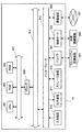
まず、図1を参照しながら、本発明の第1の実施形態に係る情報処理装置の全体構成について説明する。図1は、本実施形態に係る情報処理装置10の外観を説明するための説明図である。
(First embodiment)
<External appearance of information processing device>
First, the overall configuration of the information processing apparatus according to the first embodiment of the present invention will be described with reference to FIG. FIG. 1 is an explanatory diagram for explaining the appearance of the
図1に示すように、情報処理装置10は、2つのタッチパネルを備えた表示部(以下、タッチパネルと略記する。)101A,101Bを有し、それぞれのタッチパネルが設けられた部材が、折り畳み可能に接続されている。各タッチパネル101A,101Bには、文字や画像などといった様々な情報が表示される。各タッチパネル101A,101Bに表示されている各種情報は、操作体12の接触や移動に対応して、スクロール等の所定の処理が施される。また、タッチパネル101A,101Bには、特定処理領域が設けられていてもよい。この特定処理領域には、例えば、所定の処理を実行するためのアイコン等のオブジェクトが表示されており、この特定表示領域が選択されることにより、表示されたオブジェクトに対応付けられた所定の処理が実行される。
As illustrated in FIG. 1, the
なお、このような折り畳み式の情報処理装置10において、ユーザは、操作体12を操作することにより、各タッチパネル101A,101B(以下、タッチパネル101と略記する場合がある。)に対して別々に操作を行うことが可能である。また、ユーザは、操作体12を操作することにより、タッチパネル101A,101Bにまたがる操作を行うことも可能である。
In such a foldable
また、情報処理装置10は、操作体12の接触や移動に対し、オブジェクトの選択や表示内容の移動といった特定の処理のみを実行するわけではない。例えば、操作体12がタッチパネル101に接触した状態で所定の軌跡を描きながら移動した場合、情報処理装置10は、操作体12が描いた軌跡に対応する所定の処理を実行する。つまり、情報処理装置10は、ジェスチャー入力機能を有している。例えば、所定のジェスチャーが入力された場合に、そのジェスチャーに対応付けられているアプリケーションが起動したり、あるいは、そのジェスチャーに対応付けられている所定の処理が実行されたりする。
Further, the
操作体12としては、例えば、ユーザの指等が用いられる。また、操作体12として、例えば、スタイラスやタッチペン等が用いられることもある。また、タッチパネル101が光学式のものである場合、任意の物体が操作体12になり得る。例えば、タッチパネル101が光学式のものである場合、タッチパネル101の押圧が難しいブラシのような軟質の道具も操作体12として用いることができる。さらに、タッチパネル101がインセル型の光学式タッチパネルである場合、タッチパネル101に陰影が映るものであれば、どのような物体でも操作体12になり得る。
As the
ここで、インセル型の光学式タッチパネルについて簡単に説明する。光学式タッチパネルには、いくつかの種類がある。例えば、液晶ディスプレイを構成する液晶パネルの外枠に光学センサが設けられており、この光学センサにより液晶パネルに接触した操作体12の位置や移動方向が検知される方式の光学式タッチパネルが比較的良く知られている。この方式とは異なり、インセル型の光学式タッチパネルは、液晶パネルに光学式センサアレイを搭載し、この光学式センサアレイにより液晶パネルに接触又は近接した操作体12の位置や移動方向を検知する機構を有するものである。
Here, the in-cell type optical touch panel will be briefly described. There are several types of optical touch panels. For example, an optical sensor is provided on an outer frame of a liquid crystal panel constituting a liquid crystal display, and an optical touch panel of a type in which the position and moving direction of the operating
より詳細には、光学式タッチパネルのガラス基板上に光センサおよびリード回路が形成されており、その光センサにより外部から入射される光が検知され、その強度がリード回路により読み出されることで操作体12の陰影が認識される。このように、インセル型の光学式タッチパネルにおいては、操作体12の陰影に基づいて操作体12の形状や接触面積等が認識できる。そのため、他の光学式タッチパネルでは難しいとされていた接触「面」による操作が実現可能になる。また、インセル型の光学式タッチパネルを適用することにより、認識精度の向上や表示品質の向上、さらには、それを搭載した液晶ディスプレイ等におけるデザイン性の向上というメリットが得られる。
More specifically, an optical sensor and a lead circuit are formed on the glass substrate of the optical touch panel, and light incident from the outside is detected by the optical sensor, and the intensity is read by the lead circuit, whereby the operating body is read. Twelve shades are recognized. As described above, in the in-cell type optical touch panel, the shape, the contact area, and the like of the
なお、情報処理装置10の機能は、例えば、携帯情報端末、携帯電話、携帯ゲーム機、携帯ミュージックプレーヤ、放送機器、パーソナルコンピュータ、カーナビゲーションシステム、または、情報家電等により実現される。
Note that the functions of the
<情報処理装置の構成について>
続いて、図2を参照しながら、本実施形態に係る情報処理装置の構成について、詳細に説明する。図2は、本実施形態に係る情報処理装置の構成を説明するためのブロック図である。
<Configuration of information processing device>
Next, the configuration of the information processing apparatus according to the present embodiment will be described in detail with reference to FIG. FIG. 2 is a block diagram for explaining the configuration of the information processing apparatus according to the present embodiment.
本実施形態に係る情報処理装置10は、例えば図2に示したように、2つのタッチパネル101A,101Bと、表示制御部105と、オブジェクト選択部107と、方向検知部109と、オブジェクト移動制御部111と、記憶部117と、を主に備える。
For example, as illustrated in FIG. 2, the
タッチパネル101A,101Bは、本実施形態に係る情報処理装置10に設けられた操作入力部である。これらのタッチパネル101は、上述のような静電式タッチパネルであっても、圧力感知型のタッチパネルであっても、光学式タッチパネルであってもよく、インセル型の光学式タッチパネルであってもよい。これらのタッチパネル101は、情報処理装置10が備えるディスプレイデバイス等の表示部(図示せず。)と一体に形成されていてもよいし、別体として形成されていてもよい。このタッチパネル101は、さらに、入力位置検出部103を備える。
The
入力位置検出部103は、操作体12によって接触されたタッチパネル101の位置を検出する。入力位置検出部103は、操作体12により接触された際にタッチパネル101に掛かった押圧力を検知できるように構成されていてもよい。また、入力位置検出部103は、操作体12により直接接触されていなくても、タッチパネル101に近接したタッチパネル101上の空間に操作体12が存在するのを検知し、接触位置として認識できる機能を有していてもよい。つまり、ここで言う接触位置は、操作体12がタッチパネル101の画面上で空を描くように行った動作に対する位置情報を含むものであってもよい。
The input
入力位置検出部103は、検出した接触位置に関する情報(より詳細には、接触位置の座標)を、入力位置情報として、後述する表示制御部105、オブジェクト選択部107および方向検知部109に伝送する。例えば、図3に示したように、検出した接触位置が1箇所である場合には、入力位置検出部103は、入力位置情報として、1つの座標(X1,Y1)を出力する。また、検出した接触位置が2箇所である場合には、入力位置検出部103は、検出した複数の座標(X1,Y1)、(X2、Y2)を出力する。
The input
表示制御部105は、例えば、CPU(Central Processing Unit)、ROM(Read Only Memory)、RAM(Random Access Memory)等から構成されている。表示制御部105は、タッチパネル101に表示される内容を制御する制御手段である。例えば、表示制御部105は、後述する記憶部117に記録された任意の画像データのサムネイル画像や、写真やアルバムジャケット等の画像といったオブジェクトデータを読み出して、タッチパネル101に表示させる。このとき、表示制御部105は、タッチパネル101に対してオブジェクトの表示位置を指定し、その表示位置にオブジェクトデータを表示させる。そのため、表示制御部105には、タッチパネル101A,101Bに表示されるオブジェクトの表示位置等を示す情報が保持されている。オブジェクトの表示位置等を示す情報は、表示制御部105からオブジェクト選択部107に伝送される。
The
表示制御部105には、入力位置検出部103から入力位置情報が入力される。例えば、タッチパネル101A,101Bに接触している操作体12が移動すると、表示制御部105には、入力位置検出部103からリアルタイムに入力位置情報が入力される。表示制御部105は、情報処理装置10が有するオブジェクトを後述する記憶部117等から取得し、表示画面に表示させる。また、後述するオブジェクト選択部107から、選択されたオブジェクトに関する情報が入力された場合には、表示制御部105は、選択されたオブジェクトを強調するように表示を変更することが可能である。例えば、表示制御部105は、選択されたオブジェクトの明るさ(明度)を明るくして、選択されなかったオブジェクトの明るさを暗くするような制御を行うことが可能である。
Input position information is input to the
オブジェクト選択部107は、例えば、CPU、ROM、RAM等から構成されている。オブジェクト選択部107には、入力位置検出部103から入力位置情報が入力される。さらに、オブジェクト選択部107には、表示制御部105からオブジェクト等の表示位置を示す情報も入力される。そこで、オブジェクト選択部107は、入力位置検出部103から入力された入力位置情報と、表示制御部105から入力された表示位置を示す情報とを比較する。そして、オブジェクト選択部107は、操作体12によって選択されたオブジェクトを検知する。この処理により、オブジェクト選択部107は、選択された動画コンテンツのオブジェクトや、サムネイル画像といったオブジェクト等に関する情報を、表示制御部105や、後述するオブジェクト移動制御部111等に伝送する。
The
方向検知部109は、例えば、CPU、ROM、RAM等から構成されている。方向検知部109は、入力位置検出部103から伝送された入力位置情報である座標値を用いて、操作体12の移動方向を検知する。
The
より詳細には、方向検知部109は、所定の時間間隔毎(例えば、数ミリ秒〜数百ミリ秒毎)に伝送される入力位置情報の変化に基づいて、操作体12の移動方向を検知する。例えば、図4に示したように、方向検知部109には、操作体12の移動の有無を判定するために利用される移動判定エリアが設定されている。この移動判定エリアは、タッチパネル101における隣接する2つの接触位置を区別可能な分解能等の性能に応じて、任意の広さに設定することが可能であり、例えば、半径10ピクセル程度とすることができる。方向検知部109は、伝送される入力位置情報が、この移動判定エリアの範囲を超えて変化した場合に、操作体12は移動したと判断する。また、伝送される入力位置情報が、移動判定エリアの範囲を超えないような変化をした場合には、方向検知部109は、操作体12により、いわゆるタッピング動作がなされたと判断することが可能である。この操作体12が移動したか否かに関する判断は、同じタイミングで伝送された全ての入力位置情報に対して行われる。すなわち、同じタイミングで2個の座標値が入力位置情報として伝送された場合には、方向検知部109は、この2個の座標値それぞれの時間変化について上述のような判断を行う。
More specifically, the
また、伝送された入力位置情報が、移動判定エリアの範囲を超えて変化した場合に、方向検知部109は、伝送された入力位置情報が時間変化と共に描く軌跡がつくるベクトルの方向を、移動方向として検知する。また、上記ベクトルの大きさが、操作体12の移動量となる。
In addition, when the transmitted input position information changes beyond the range of the movement determination area, the
例えば、図4に示したように、入力位置検出部103から、時刻t1において座標A(X1(t1),Y1(t1))が伝送され、この入力位置情報に対応する時刻t2における位置が、座標A’(X3(t2),Y3(t2))であった場合を考える。この際、方向検知部109は、始点座標A、終点座標A’で定義されるベクトルV1が表す方向を、座標Aに接触した操作体12の移動方向として検知する。また、方向検知部109は、ベクトルV1の大きさを、操作体12の移動量とする。
For example, as shown in FIG. 4, the coordinates A (X1 (t1), Y1 (t1)) are transmitted from the input
また、図4に示したように、入力位置検出部103から、時刻t1において、座標A(X1(t1),Y1(t1))および座標B(X2(t1),Y2(t1))が伝送された場合を考える。この場合にも、それぞれの入力位置情報に対応する時刻t2における座標A’およびB’に基づいて、それぞれベクトルV1およびベクトルV2が定義される。ここで、方向検知部109は、同じタイミングで複数個の入力位置情報が伝送された場合には、それぞれの入力位置情報から生成される個々のベクトルを移動方向とするのではなく、以下のような方法で、移動方向を決定する。
Further, as shown in FIG. 4, the coordinate A (X1 (t1), Y1 (t1)) and the coordinate B (X2 (t1), Y2 (t1)) are transmitted from the input
例えば、図4に示したように、方向検知部109は、2つのベクトルV1およびV2の和に該当する方向を、移動方向として決定することが可能である。また、2個の入力位置座標が伝送された場合だけでなく、3個以上の入力位置座標が同じタイミングで伝送された場合であっても、個々の入力位置座標の時間変化に伴って定義されるベクトル同士の和をとることで、移動方向を一意に決定することが可能である。複数のベクトルに基づいて移動方向を決定した場合には、方向検知部109は、ベクトルの和の大きさを移動量としてもよく、いずれか一つのベクトルの大きさを移動量としてもよい。
For example, as illustrated in FIG. 4, the
また、図4に示したように、方向検知部109は、2つのベクトルV1およびV2のなす角θに着目して、移動方向を決定することも可能である。この場合においても、方向検知部109は、3個以上の入力位置座標が同じタイミングで伝送された際に、まず、個々の入力位置座標の時間変化に伴って定義されるベクトルを定義する。続いて、方向検知部109は、定義したベクトルの中から1つのベクトルに着目し、この1つのベクトルと他のベクトルとのなす角を考慮することで、移動方向を決定することができる。すなわち、なす角θが所定の閾値よりも小さく、例えば鋭角である場合には、それぞれのベクトルは、同様の方向を指していることを示す。また、なす角θが所定の閾値よりも大きく、例えば鈍角である場合には、それぞれのベクトルは、互いに離れていくような方向を指していることを示す。
As shown in FIG. 4, the
また、方向検知部109は、検知した操作体12の移動量と、移動時間とに基づいて、操作体12の移動速度や加速度等を算出することができる。方向検知部109は、移動量や移動速度や加速度等に基づいて、操作体12による操作が、いわゆるドラッグ操作であるのか、または、フリック操作であるのかを判定することが可能である。ドラッグ操作とは、タッチパネル101上で操作体12を引きずる操作であり、ほぼ一定の移動速度で操作体12が移動すると考えられる。また、フリック操作とは、タッチパネル101を弾く操作であり、短時間に速い移動速度(または、大きな加速度)で操作体12が移動すると考えられる。
In addition, the
方向検知部109は、上述のようにして検知された操作体12の移動方向および移動量を含む方向情報を、オブジェクト移動制御部111に伝送する。また、方向検知部109は、操作体12によってなされた操作がドラッグ操作であるのか、フリック操作であるのかの判定結果を、あわせてオブジェクト移動制御部111に伝送する。
The
オブジェクト移動制御部111は、例えば、CPU、ROM、RAM等から構成されている。オブジェクト移動制御部111は、オブジェクト選択部107から、操作体12によって選択されたオブジェクトに関する情報(以下、選択オブジェクト情報と称する。)が伝送される。また、オブジェクト移動制御部111には、方向検知部109から、操作体12の移動方向および移動量に関する情報と、操作体12によって行われた操作の種類に関する情報(以下、操作種別情報と称する。)とが伝送される。さらに、オブジェクト移動制御部111には、表示制御部105からオブジェクト等の表示位置を示す情報が入力される。
The object
オブジェクト移動制御部111は、伝送された選択オブジェクト情報、操作体の移動方向および移動量に関する情報、および、操作種別情報に基づいて、選択されたオブジェクトの移動制御を行う。
The object
例えば図5(a)に示したように、操作体12によって選択されたオブジェクト151に対してドラッグ操作がなされた場合には、オブジェクト移動制御部111は、選択されたオブジェクト151を、同一の画面内で操作体12が描く軌跡に追随させる。すなわち、選択されたオブジェクト151に対してドラッグ操作がなされた場合には、この選択されたオブジェクト151は、画面をまたいで移動することはない。図5(a)に示した例では、操作体12によって選択されたオブジェクト151は、タッチパネル101A側に表示されているため、このオブジェクトは、タッチパネル101A内で操作体12の動きに追随する。
For example, as illustrated in FIG. 5A, when a drag operation is performed on the
また、図5(b)に示したように、操作体12によって選択されたオブジェクト151に対してフリック操作(オブジェクトを弾く操作)がなされた場合には、オブジェクト移動制御部111は、選択されたオブジェクト151を、操作体12の移動方向に素早くスクロールさせる。スクロールの際、操作体12がオブジェクト151から離れた以降も、操作体12の移動速度、移動量、加速度等に応じて、オブジェクト151は、慣性運動を行う。すなわち、オブジェクト移動制御部111は、操作体12がオブジェクト151から離れた後、オブジェクトを一定の移動速度で移動させた後に移動速度を徐々に低下させ、ある程度オブジェクトが自動的に移動した後に停止するように制御を行う。また、オブジェクト151が移動する位置は、例えば、操作体12の移動速度や移動量等に応じて決定される。また、図5(b)に示したように、フリック操作がなされたオブジェクト151は、画面をまたいで移動することが可能である。すなわち、図5(b)に示した例では、フリック操作がなされたオブジェクト151はタッチパネル101A側に表示されているが、フリック操作の状況に応じて、オブジェクト151はタッチパネル101B側に移動することが可能である。
Further, as shown in FIG. 5B, when a flick operation (an operation of flipping an object) is performed on the
上述のようなオブジェクトの移動制御を行うオブジェクト移動制御部111は、移動位置算出部113と、表示位置補正部115と、を更に備える。
The object
移動位置算出部113は、例えば、CPU、ROM、RAM等から構成されている。移動位置算出部113は、伝送された選択オブジェクト情報、操作体の移動方向および移動量に関する情報、および、操作種別情報に基づいて、選択されたオブジェクトの移動位置を算出する。
The movement
より詳細には、移動位置算出部113は、操作種別情報がドラッグ操作を表すものである場合には、操作体12が接触しているオブジェクトを表す画像内の点が、タッチパネル101における移動後の操作体12の座標と一致するように、移動位置を算出する。また、移動位置算出部113は、操作種別情報がフリック操作を表すものである場合には、操作体12の移動方向、移動量、移動速度、加速度等に基づいて、選択されたオブジェクトが自動的に移動して最終的に停止する位置を算出する。なお、最終的に停止する位置は、オブジェクトの重心等といった特徴的な点が停止する位置座標であってもよく、オブジェクトの端部(例えば矩形のオブジェクトである場合にはオブジェクトの辺)が位置する座標であってもよい。
More specifically, when the operation type information represents a drag operation, the movement
移動位置算出部113がオブジェクトの移動位置を算出することで、オブジェクト移動制御部111は、表示画面上である大きさに表示されているオブジェクトが、最終的にどの位置に表示されることとなるのかを知ることができる。
When the movement
移動位置算出部113は、算出したオブジェクトの移動位置に関する情報(以下、移動位置情報と称する。)を、表示位置補正部115に伝送する。
The movement
表示位置補正部115は、例えば、CPU、ROM、RAM等から構成されている。表示位置補正部115は、移動位置算出部113から伝送された、選択されたオブジェクトの移動位置情報に基づいて、オブジェクトの表示位置の補正を実行するか否かを判断する。また、表示位置の補正を実行する場合には、表示位置補正部115は、補正後のオブジェクトの表示位置を決定する。
The display
より詳細には、表示位置補正部115は、伝送されたオブジェクトの移動位置情報と、当該オブジェクトの表示画面上での大きさとに基づいて、移動後のオブジェクトの少なくとも一部が、非表示領域に含まれるか否かを判定する。換言すれば、表示位置補正部115は、移動位置情報と、オブジェクトの表示画面上での大きさと、表示画面(すなわちタッチパネル101)の大きさとに基づいて、移動後のオブジェクトが全て同一のタッチパネル101内に表示されるか否かを判断する。ここで、非表示領域とは、タッチパネル101Aとタッチパネル101Bとの間に位置する連結部に該当し、オブジェクトを含む各種情報が表示されない領域である。移動後のオブジェクトの少なくとも一部が非表示領域に含まれる場合、該当するオブジェクトは2つのタッチパネル101A,101Bにまたがって表示されることとなり、非表示領域によってオブジェクトが分断されて表示される。そのため、表示位置補正部115は、移動後のオブジェクトに対して、表示位置の補正を行う旨の判断を下す。また、移動後のオブジェクトが全て同一のタッチパネル101内に表示される場合には、表示位置補正部115は、移動後のオブジェクトに対して、表示位置の補正を行わない旨の判断を下す。
More specifically, the display
また、表示位置の補正を行う旨の判断を下した場合には、表示位置補正部115は、移動後のオブジェクト画像の重心が、2つのタッチパネル101A,101Bのどちらに属しているかに応じて、オブジェクトを移動させる方向を決定する。以下に、オブジェクトの移動方向の決定方法について、図6および図7を参照しながら、詳細に説明する。
When the display
例えば図6(a)に示したように、移動後のオブジェクト151が非表示領域153によって分断されており、オブジェクト画像の重心155がタッチパネル101Aに属している場合を考える。この場合、表示位置補正部115は、図6(b)に示したように、該当するオブジェクト151を重心155が属するタッチパネル101A側に移動させるようにオブジェクト移動制御部111に要請する。
For example, as shown in FIG. 6A, a case is considered where the moved
また、表示位置補正部115は、該当するオブジェクトの移動量を、重心155が属さない側のタッチパネル101にはみ出した大きさ以上に設定する。すなわち、図6(a)に示した例では、タッチパネル101B側にはみ出した長さdを、移動量の下限値に設定する。
In addition, the display
表示位置補正部115は、決定した移動方向と移動量の下限値を、オブジェクト移動制御部111に伝送し、オブジェクト移動制御部111は、該当するオブジェクト151の表示位置を上側に移動させる。このように表示位置を補正することで、2画面にまたがって表示されていたオブジェクトは、1画面で表示されることとなる。
The display
他方、例えば図7(a)に示したように、移動後のオブジェクト151が非表示領域153によって分断されており、オブジェクト画像の重心155がタッチパネル101B側に属している場合を考える。この場合、表示位置補正部115は、図7(b)に示したように、該当するオブジェクト151を重心155が属するタッチパネル101B側に移動させるようにオブジェクト移動制御部111に要請する。また、この場合についても、表示位置補正部115は、移動量の下限値を、タッチパネル101A側にはみ出した長さdに設定する。
On the other hand, as shown in FIG. 7A, for example, consider a case where the moved
なお、図6(b)および図7(b)では、オブジェクト移動制御部111が、該当するオブジェクト151を2dだけ移動させた場合について図示している。また、オブジェクト移動制御部111は、オブジェクトの表示位置の補正を行う際に、停止しつつあったオブジェクトを再加速させて該当するタッチパネル側に飛び出させるなどのアニメーションを付加してもよい。このようなアニメーションを付加することで、ユーザに対して、「連結部(すなわち、非表示領域)にオブジェクトを配置できない」旨を意識させることができる。
FIGS. 6B and 7B show a case where the object
このように、表示位置補正部115は、原則としてオブジェクトの重心がどちらのタッチパネル101に属するかに基づいて、補正のための移動方向を決定する。しかしながら、以下のような場合には、表示位置補正部115は、オブジェクトの重心の位置ではなく、操作体12の移動方向に基づいて、補正のための移動方向を決定してもよい。
As described above, the display
ケース1:表示画面が変更になることでオブジェクトの属性が変化する場合
ケース2:表示画面の占有面積が大きなオブジェクトに対して操作がなされた場合
ケース3:非表示領域に近接するオブジェクトに対して操作がなされた場合
Case 1: When the attribute of an object changes due to a change in the display screen Case 2: When an operation is performed on an object with a large display screen area Case 3: For an object close to the non-display area When an operation is performed
[ケース1:表示画面が変更になることでオブジェクトの属性が変化する場合]
まず、図8を参照しながら、表示画面が変更になることでオブジェクトの属性が変化する場合における補正処理について、詳細に説明する。
[Case 1: When the attribute of an object changes as the display screen changes]
First, with reference to FIG. 8, the correction process in the case where the attribute of the object changes due to the change of the display screen will be described in detail.
本ケースは、タッチパネル101Aに表示されているオブジェクトの属性と、タッチパネル101Bに表示されているオブジェクトの属性とが異なっており、オブジェクトを異なる画面に移動させることで、オブジェクトの属性が変化する場合である。オブジェクトの属性の例として、例えば、オブジェクトに対応する情報の所有者、オブジェクトの所在を表す所在情報等を挙げることができる。
In this case, the attribute of the object displayed on the
図8において、タッチパネル101AにはユーザAが所有するコンテンツ等に関するオブジェクトが表示されており、タッチパネル101BにはユーザBが所有するコンテンツ等に関するオブジェクトが表示されているものとする。この場合、タッチパネル101Aに表示されているオブジェクトをタッチパネル101Bへと移動させることで、該当するオブジェクトの所有者を表す情報がユーザBに変更になるものとする。
In FIG. 8, it is assumed that an object related to contents and the like owned by the user A is displayed on the
このような場合に、あるユーザがオブジェクト151に対して下方向のフリック操作をした時点で、ユーザは該当するオブジェクト151をタッチパネル101B側へ移動させるという意図を有していることが判断できる。そこで、図8(a)に示したように、オブジェクトが両画面にまたがって表示され、オブジェクトの重心がタッチパネル101Aに属していた場合であっても、ユーザの意図を汲み取って、表示位置補正部115は、タッチパネル101B側への移動を要請する。また、オブジェクト151の重心155がタッチパネル101B側に属していた場合には、表示位置補正部115は、補正のための移動方向を、原則どおり重心が存在する側のタッチパネルに向かう方向に設定する。
In such a case, when a certain user performs a downward flick operation on the
[ケース2:表示画面の占有面積が大きなオブジェクトに対して操作がなされた場合]
次に、図9を参照しながら、表示画面の占有面積が大きなオブジェクトに対して操作がなされた場合における補正処理について、詳細に説明する。
[Case 2: When an operation is performed on an object having a large display screen area]
Next, the correction processing when an operation is performed on an object having a large occupied area on the display screen will be described in detail with reference to FIG.
本ケースは、図9(a)に示したように、表示画面の占有面積が大きなオブジェクトに対して、フリック操作がなされた場合における補正処理である。図9(a)に示したような大きなオブジェクトに対してフリック操作がなされ、図9(b)に示したように、両画面にまたがってオブジェクトが表示されることとなった場合を考える。 In this case, as shown in FIG. 9A, correction processing is performed when a flick operation is performed on an object having a large occupied area on the display screen. Consider a case in which a flick operation is performed on a large object as shown in FIG. 9A and the object is displayed across both screens as shown in FIG. 9B.
このような場合にも、上述のケース1と同様に、あるユーザがオブジェクト151に対して下方向のフリック操作をした時点で、ユーザは該当するオブジェクト151をタッチパネル101B側へ移動させるという意図を有していることが判断できる。そこで、図9(c)に示したように、オブジェクトが両画面にまたがって表示され、オブジェクトの重心がタッチパネル101Aに属していた場合であっても、ユーザの意図を汲み取って、表示位置補正部115は、タッチパネル101B側への移動を要請する。また、オブジェクト151の重心155がタッチパネル101B側に属していた場合には、表示位置補正部115は、補正のための移動方向を、原則どおり重心が存在する側のタッチパネルに向かう方向に設定する。
Even in such a case, as in the case 1 described above, when a certain user performs a downward flick operation on the
[ケース3:非表示領域に近接するオブジェクトに対して操作がなされた場合]
続いて、図10を参照しながら、非表示領域に近接するオブジェクトに対して操作がなされた場合における補正処理について、詳細に説明する。
[Case 3: When an operation is performed on an object close to the non-display area]
Next, the correction process when an operation is performed on an object close to the non-display area will be described in detail with reference to FIG.
本ケースは、図10(a)に示したように、非表示領域153に近接または隣接するオブジェクト151に対して、フリック操作がなされた場合における補正処理である。図10(a)に示したような、非表示領域153に近接するオブジェクト151に対してフリック操作がなされ、図10(b)に示したように、両画面にまたがってオブジェクトが表示されることとなった場合を考える。
In this case, as illustrated in FIG. 10A, the correction process is performed when a flick operation is performed on the
このような場合にも、上述のケース1およびケース2と同様に、あるユーザがオブジェクト151に対して下方向のフリック操作をした時点で、ユーザは該当するオブジェクト151をタッチパネル101B側へ移動させるという意図を有していることが判断できる。そこで、図10(c)に示したように、オブジェクトが両画面にまたがって表示され、オブジェクトの重心がタッチパネル101Aに属していた場合であっても、ユーザの意図を汲み取って、表示位置補正部115は、タッチパネル101B側への移動を要請する。また、オブジェクト151の重心155がタッチパネル101B側に属していた場合には、表示位置補正部115は、補正のための移動方向を、原則どおり重心が存在する側のタッチパネルに向かう方向に設定する。
Also in such a case, as in the case 1 and case 2 described above, when a certain user performs a downward flick operation on the
以上説明したように、表示位置補正部115は、オブジェクトの重心位置、または、操作体の移動方向に応じて、移動の結果両画面にまたがって表示されることとなったオブジェクトの表示位置を補正する。
As described above, the display
再び図2に戻って、本実施形態に係る情報処理装置10が有する記憶部117について説明する。
Returning to FIG. 2 again, the
記憶部117には、タッチパネル101A、101Bに表示されるオブジェクトデータが格納されている。ここで言うオブジェクトデータには、例えば、アイコン、ボタン、サムネイル等のグラフィカルユーザインターフェース(以下、GUI)を構成する任意のパーツ類が含まれる。また、記憶部117には、個々のオブジェクトデータに対し、属性情報が対応付けて格納されている。属性情報としては、例えば、オブジェクトデータまたは実体データの作成日時、更新日時、作成者名、更新者名、実体データの種別、実体データのサイズ、重要度、優先度等がある。
The
また、記憶部117には、オブジェクトデータに対応する実体データも相互に対応付けて格納されている。ここで言う実体データは、タッチパネル101A,101Bに表示されたオブジェクトが操作された際に実行される所定の処理に対応するデータである。例えば、動画コンテンツに対応するオブジェクトデータには、その動画コンテンツのコンテンツデータが実体データとして対応付けられている。また、記憶部117には、その動画コンテンツを再生するための動画再生アプリケーションもオブジェクトデータ、コンテンツデータ、または属性情報に対応付けて格納されている。
In addition, the
記憶部117に格納されているオブジェクトデータは、表示制御部105により読み出されてタッチパネル101A,101Bに表示される。
The object data stored in the
また、記憶部117は、これらのデータ以外にも、情報処理装置10が、何らかの処理を行う際に保存する必要が生じた様々なパラメータや処理の途中経過等、または、各種のデータベース等を、適宜記憶することが可能である。この記憶部117は、入力位置検出部103、表示制御部105、オブジェクト選択部107、方向検知部109、オブジェクト移動制御部111、移動位置算出部113、表示位置補正部115等が、自由に読み書きを行うことが可能である。
Further, in addition to these data, the
以上、本実施形態に係る情報処理装置10の機能の一例を示した。上記の各構成要素は、汎用的な部材や回路を用いて構成されていてもよいし、各構成要素の機能に特化したハードウェアにより構成されていてもよい。また、各構成要素の機能を、CPU等が全て行ってもよい。従って、本実施形態を実施する時々の技術レベルに応じて、適宜、利用する構成を変更することが可能である。
Heretofore, an example of the function of the
なお、上述のような本実施形態に係る情報処理装置の各機能を実現するためのコンピュータプログラムを作製し、パーソナルコンピュータ等に実装することが可能である。また、このようなコンピュータプログラムが格納された、コンピュータで読み取り可能な記録媒体も提供することができる。記録媒体は、例えば、磁気ディスク、光ディスク、光磁気ディスク、フラッシュメモリなどである。また、上記のコンピュータプログラムは、記録媒体を用いずに、例えばネットワークを介して配信してもよい。 It should be noted that a computer program for realizing each function of the information processing apparatus according to the present embodiment as described above can be produced and installed in a personal computer or the like. In addition, a computer-readable recording medium storing such a computer program can be provided. The recording medium is, for example, a magnetic disk, an optical disk, a magneto-optical disk, a flash memory, or the like. Further, the above computer program may be distributed via a network, for example, without using a recording medium.
<情報処理方法について>
次に、図11を参照しながら、本実施形態に係る情報処理方法について、詳細に説明する。図11は、本実施形態に係る情報処理方法を説明するための流れ図である。
<About information processing method>
Next, the information processing method according to the present embodiment will be described in detail with reference to FIG. FIG. 11 is a flowchart for explaining the information processing method according to the present embodiment.
まず、情報処理装置10のユーザは、指やスタイラス等の操作体12を用いてタッチパネル101A,101Bを操作し、オブジェクトの一覧表示等を行うアプリケーションに関連づけられたアイコン等のオブジェクトを選択する。これにより、情報処理装置10は、選択されたオブジェクトに関連づけられたアプリケーションを起動する(ステップS101)。
First, the user of the
続いて、情報処理装置10は、ユーザによる入力を待ち受け、アプリケーションの終了操作が入力されたか否かを判断する(ステップS103)。ユーザによりアプリケーションの終了操作が入力された場合には、情報処理装置10は、起動中のアプリケーションを終了する(ステップS105)。
Subsequently, the
また、アプリケーションの終了操作が入力されない場合には、情報処理装置10は、更に、ユーザによる入力を待ち受ける。
Further, when the application termination operation is not input, the
ユーザが、操作体12を操作して、タッチパネル101Aまたはタッチパネル101Bに触ると、該当するタッチパネルの入力位置検出部103は、操作体12がタッチパネル101に接触している位置を検出する(ステップS107)。入力位置検出部103は、接触位置に該当する座標値を、入力位置情報として表示制御部105、オブジェクト選択部107および方向検知部109に伝送する。
When the user operates the
オブジェクト選択部107は、伝送された入力位置情報と、表示制御部105から取得したオブジェクトの表示位置に関する情報とに基づいて、操作体12がオブジェクトと接触しているか否かを判定する(ステップS109)。操作体12がオブジェクトと接触していないと判定した場合には、情報処理装置10は再びステップS107に戻って、入力位置の検出を行う。また、操作体12がオブジェクトと接触していると判定した場合には、オブジェクト選択部107は、選択されたオブジェクトに関する情報をオブジェクト移動制御部111に伝送する。オブジェクト移動制御部111中の移動位置算出部113は、オブジェクト選択部107から伝送されたオブジェクトについて、方向検知部109から伝送された操作体12の移動方向に基づいて移動位置の算出を行う。オブジェクト移動制御部111は、算出された移動位置に応じて、オブジェクトを移動させる(ステップS111)。これにより、操作体12によって選択されたオブジェクトは、操作体12の移動に追随して移動することとなる。
The
また、オブジェクト選択部107によりオブジェクトへの操作体12の接触が終了した旨が判定されると(ステップS113)、移動位置算出部113は、操作の種類に応じて、オブジェクトの停止位置を算出する(ステップS115)。すなわち、操作体12による操作がドラッグ操作である場合には、移動位置算出部113は、操作体12の接触が終了した時点で、選択されていたオブジェクトの移動を停止する。また、操作体12による操作がフリック操作である場合には、移動位置算出部113は、移動量、移動速度、加速度等に応じてオブジェクトの停止位置を算出し、オブジェクト移動制御部111は、算出した移動位置までオブジェクトを自動的に移動させる。
When the
ここで、表示位置補正部115は、算出されたオブジェクトの停止位置と、オブジェクト画像の大きさと、表示領域の大きさとに基づいて、オブジェクト画像の少なくとも一部が非表示領域に含まれるか否かを判定する(ステップS117)。オブジェクト画像の少なくとも一部が非表示領域に存在しない場合には、情報処理装置10はステップS103に戻ってユーザによる操作を待ち受ける。他方、オブジェクト画像の少なくとも一部が非表示領域に存在する場合、表示位置補正部115は、移動方向の考慮が必要か否かを判断する(ステップS119)。
Here, the display
より詳細には、表示位置補正部115は、各タッチパネル101に表示されているオブジェクトの属性情報や、オブジェクト画像の大きさや、オブジェクトの表示位置等を参照して、移動方向の考慮が必要か否かを判断する。前述のケース1〜ケース3のようにユーザの操作意図を考慮したほうが良い場合には、表示位置補正部115は、オブジェクト画像の重心位置に着目するのではなく、操作体12の移動方向に応じて、オブジェクトの表示位置を補正する(ステップS121)。他方、ユーザによる操作意図を考慮しなくても良い場合には、表示位置補正部115は、オブジェクト画像の重心位置に応じて、オブジェクトの表示位置を補正する(ステップS123)。
More specifically, the display
これらの補正処理が終了すると、情報処理装置10はステップS103に戻ってユーザによる操作を待ち受ける。
When these correction processes are completed, the
以上説明したように、本実施形態に係る情報処理方法では、オブジェクト画像の少なくとも一部が非表示領域に含まれる場合には、オブジェクトの表示位置または操作体の移動方向に基づいて、非表示領域からオブジェクトを移動させることが可能となる。 As described above, in the information processing method according to the present embodiment, when at least a part of the object image is included in the non-display area, the non-display area is based on the display position of the object or the moving direction of the operating tool. It is possible to move an object from
<ハードウェア構成について>
次に、図12を参照しながら、本発明の各実施形態に係る情報処理装置10のハードウェア構成について、詳細に説明する。図12は、本発明の各実施形態に係る情報処理装置10のハードウェア構成を説明するためのブロック図である。
<About hardware configuration>
Next, the hardware configuration of the
情報処理装置10は、主に、CPU901と、ROM903と、RAM905と、を備える。また、情報処理装置10は、更に、ホストバス907と、ブリッジ909と、外部バス911と、インターフェース913と、入力装置915と、出力装置917と、ストレージ装置919と、ドライブ921と、接続ポート923と、通信装置925とを備える。
The
CPU901は、演算処理装置および制御装置として機能し、ROM903、RAM905、ストレージ装置919、またはリムーバブル記録媒体927に記録された各種プログラムに従って、情報処理装置10内の動作全般またはその一部を制御する。ROM903は、CPU901が使用するプログラムや演算パラメータ等を記憶する。RAM905は、CPU901の実行において使用するプログラムや、その実行において適宜変化するパラメータ等を一次記憶する。これらはCPUバス等の内部バスにより構成されるホストバス907により相互に接続されている。
The
ホストバス907は、ブリッジ909を介して、PCI(Peripheral Component Interconnect/Interface)バスなどの外部バス911に接続されている。
The
入力装置915は、例えば、マウス、キーボード、タッチパネル、ボタン、スイッチおよびレバーなどユーザが操作する操作手段である。また、入力装置915は、例えば、赤外線やその他の電波を利用したリモートコントロール手段(いわゆる、リモコン)であってもよいし、情報処理装置10の操作に対応した携帯電話やPDA等の外部接続機器929であってもよい。さらに、入力装置915は、例えば、上記の操作手段を用いてユーザにより入力された情報に基づいて入力信号を生成し、CPU901に出力する入力制御回路などから構成されている。情報処理装置10のユーザは、この入力装置915を操作することにより、情報処理装置10に対して各種のデータを入力したり処理動作を指示したりすることができる。
The
出力装置917は、取得した情報をユーザに対して視覚的または聴覚的に通知することが可能な装置で構成される。このような装置として、CRTディスプレイ装置、液晶ディスプレイ装置、プラズマディスプレイ装置、ELディスプレイ装置およびランプなどの表示装置や、スピーカおよびヘッドホンなどの音声出力装置や、プリンタ装置、携帯電話、ファクシミリなどがある。出力装置917は、例えば、情報処理装置10が行った各種処理により得られた結果を出力する。具体的には、表示装置は、情報処理装置10が行った各種処理により得られた結果を、テキストまたはイメージで表示する。他方、音声出力装置は、再生された音声データや音響データ等からなるオーディオ信号をアナログ信号に変換して出力する。
The
ストレージ装置919は、情報処理装置10の記憶部の一例として構成されたデータ格納用の装置である。ストレージ装置919は、例えば、HDD(Hard Disk Drive)等の磁気記憶部デバイス、半導体記憶デバイス、光記憶デバイス、または光磁気記憶デバイス等により構成される。このストレージ装置919は、CPU901が実行するプログラムや各種データ、および外部から取得した音響信号データや画像信号データなどを格納する。
The
ドライブ921は、記録媒体用リーダライタであり、情報処理装置10に内蔵、あるいは外付けされる。ドライブ921は、装着されている磁気ディスク、光ディスク、光磁気ディスク、または半導体メモリ等のリムーバブル記録媒体927に記録されている情報を読み出して、RAM905に出力する。また、ドライブ921は、装着されている磁気ディスク、光ディスク、光磁気ディスク、または半導体メモリ等のリムーバブル記録媒体927に記録を書き込むことも可能である。リムーバブル記録媒体927は、例えば、DVDメディア、HD−DVDメディア、Blu−rayメディア等である。また、リムーバブル記録媒体927は、コンパクトフラッシュ(登録商標)(CompactFlash:CF)、メモリースティック、または、SDメモリカード(Secure Digital memory card)等であってもよい。また、リムーバブル記録媒体927は、例えば、非接触型ICチップを搭載したICカード(Integrated Circuit card)または電子機器等であってもよい。
The
接続ポート923は、機器を情報処理装置10に直接接続するためのポートである。接続ポート923の一例として、USB(Universal Serial Bus)ポート、i.Link等のIEEE1394ポート、SCSI(Small Computer System Interface)ポート等がある。接続ポート923の別の例として、RS−232Cポート、光オーディオ端子、HDMI(High−Definition Multimedia Interface)ポート等がある。この接続ポート923に外部接続機器929を接続することで、情報処理装置10は、外部接続機器929から直接音響信号データや画像信号データを取得したり、外部接続機器929に音響信号データや画像信号データを提供したりする。
The
通信装置925は、例えば、通信網931に接続するための通信デバイス等で構成された通信インターフェースである。通信装置925は、例えば、有線または無線LAN(Local Area Network)、Bluetooth、またはWUSB(Wireless USB)用の通信カード等である。また、通信装置925は、光通信用のルータ、ADSL(Asymmetric Digital Subscriber Line)用のルータ、または、各種通信用のモデム等であってもよい。この通信装置925は、例えば、インターネットや他の通信機器との間で、例えばTCP/IP等の所定のプロトコルに則して信号等を送受信することができる。また、通信装置925に接続される通信網931は、有線または無線によって接続されたネットワーク等により構成され、例えば、インターネット、家庭内LAN、赤外線通信、ラジオ波通信または衛星通信等であってもよい。
The
以上、本発明の各実施形態に係る情報処理装置10の機能を実現可能なハードウェア構成の一例を示した。上記の各構成要素は、汎用的な部材を用いて構成されていてもよいし、各構成要素の機能に特化したハードウェアにより構成されていてもよい。従って、本実施形態を実施する時々の技術レベルに応じて、適宜、利用するハードウェア構成を変更することが可能である。
Heretofore, an example of the hardware configuration capable of realizing the function of the
<まとめ>
以上説明したように、本実施形態に係る情報処理装置および情報処理方法によれば、複数の表示画面を用いて各種情報を表示する情報処理装置であっても、1つの表示画面を用いて各種情報を表示する情報処理装置と同様の情報の提示が可能となる。本実施形態に係る情報処理装置では、非表示領域にオブジェクトが配置されないため、ユーザがオブジェクトの内容を把握しやすい、オブジェクトが分断されて表示されることがない、オブジェクトサイズが本来あるべき通りに表示される等といった利点が生ずる。
<Summary>
As described above, according to the information processing apparatus and the information processing method according to the present embodiment, even if the information processing apparatus displays various information using a plurality of display screens, It is possible to present information similar to that of an information processing apparatus that displays information. In the information processing apparatus according to the present embodiment, since the object is not arranged in the non-display area, the user can easily grasp the contents of the object, the object is not divided and displayed, and the object size is as originally intended. Advantages such as being displayed arise.
また、非表示領域にオブジェクトの一部が位置する場合に、アニメーションを伴って表示位置の補正を行うことで、ユーザに対して「連結部にオブジェクトを配置することができない」旨を伝達することができる。 In addition, when a part of an object is located in the non-display area, the display position is corrected with an animation to notify the user that “the object cannot be arranged at the connecting portion”. Can do.
また、オブジェクトの大きさ、表示位置、属性情報等に応じて表示位置補正の判定基準を変化させることにより、ユーザにストレスを感じさせること無くオブジェクトのレイアウト補正が可能となり、操作性を向上させることができる。 Also, by changing the display position correction criteria according to the size, display position, attribute information, etc. of the object, the layout of the object can be corrected without causing the user to feel stress, thereby improving operability. Can do.
以上、添付図面を参照しながら本発明の好適な実施形態について詳細に説明したが、本発明はかかる例に限定されない。本発明の属する技術の分野における通常の知識を有する者であれば、特許請求の範囲に記載された技術的思想の範疇内において、各種の変更例または修正例に想到し得ることは明らかであり、これらについても、当然に本発明の技術的範囲に属するものと了解される。 The preferred embodiments of the present invention have been described in detail above with reference to the accompanying drawings, but the present invention is not limited to such examples. It is obvious that a person having ordinary knowledge in the technical field to which the present invention pertains can come up with various changes or modifications within the scope of the technical idea described in the claims. Of course, it is understood that these also belong to the technical scope of the present invention.
例えば、上記実施形態では、2つのタッチパネルを備えた情報処理装置を例に挙げて説明を行なったが、本発明はかかる例に限定されない。例えば、本発明は、3つ以上のタッチパネルを備えた情報処理装置に対しても、同様に適用することが可能である。 For example, in the above embodiment, the information processing apparatus including two touch panels has been described as an example, but the present invention is not limited to such an example. For example, the present invention can be similarly applied to an information processing apparatus including three or more touch panels.
10 情報処理装置
12 操作体
101 タッチパネル
103 入力位置検出部
105 表示制御部
107 オブジェクト選択部
109 方向検知部
111 オブジェクト移動制御部
113 移動位置算出部
115 表示位置補正部
117 記憶部
151 オブジェクト
153 非表示領域
DESCRIPTION OF
Claims (6)
前記表示パネル上に位置する操作体の位置を検出する入力位置検出部と、
検出された前記操作体の位置の時間変化に基づいて、前記操作体の移動方向を検知する方向検知部と、
前記操作体により選択された前記オブジェクトを前記操作体が描く軌跡に応じて移動させる際の移動位置を算出する移動位置算出部と、
算出された移動後の前記オブジェクトの少なくとも一部が前記非表示領域に位置する場合に、当該オブジェクトの表示位置または前記操作体の移動方向に基づいて、前記非表示領域から前記オブジェクトを移動させる表示位置補正部と、
を備える、情報処理装置。 A plurality of objects can be displayed, and the first and second display panels connected to each other via a connecting portion that is a non-display area where the objects are not displayed;
An input position detection unit for detecting the position of the operating body located on the display panel;
A direction detection unit that detects a moving direction of the operating body based on a detected time change of the position of the operating body;
A movement position calculation unit that calculates a movement position when moving the object selected by the operation body according to a trajectory drawn by the operation body;
A display for moving the object from the non-display area based on the display position of the object or the moving direction of the operating body when at least a part of the calculated moved object is located in the non-display area A position correction unit;
An information processing apparatus comprising:
検出された前記操作体の位置の時間変化に基づいて、前記操作体の移動方向を検知するステップと、
前記操作体により選択された前記オブジェクトを前記操作体が描く軌跡に応じて移動させる際の移動位置を算出するステップと、
算出された移動後の前記オブジェクトの少なくとも一部が前記非表示領域に位置する場合に、当該オブジェクトの表示位置または前記操作体の移動方向に基づいて、前記非表示領域から前記オブジェクトを移動させるステップと、
を含む、情報処理方法。 Detecting a position of an operating body positioned on the first and second display panels connected to each other via a connecting portion that is a non-display area in which a plurality of objects can be displayed;
Detecting the moving direction of the operating body based on the detected temporal change in the position of the operating body;
Calculating a moving position when moving the object selected by the operating body according to a trajectory drawn by the operating body;
A step of moving the object from the non-display area based on a display position of the object or a moving direction of the operating body when at least a part of the calculated moved object is located in the non-display area; When,
Including an information processing method.
前記表示パネル上に位置する操作体の位置を検出する入力位置検出機能と、
検出された前記操作体の位置の時間変化に基づいて、前記操作体の移動方向を検知する方向検知機能と、
前記操作体により選択された前記オブジェクトを前記操作体が描く軌跡に応じて移動させる際の移動位置を算出する移動位置算出機能と、
算出された移動後の前記オブジェクトの少なくとも一部が前記非表示領域に位置する場合に、当該オブジェクトの表示位置または前記操作体の移動方向に基づいて、前記非表示領域から前記オブジェクトを移動させる表示位置補正機能と、
を実現させるためのプログラム。
A computer having a first display panel and a second display panel connected to each other via a connecting portion that can display a plurality of objects and is a non-display area where the objects are not displayed.
An input position detection function for detecting the position of the operating body located on the display panel;
A direction detection function for detecting the moving direction of the operating body based on the detected temporal change in the position of the operating body;
A movement position calculation function for calculating a movement position when moving the object selected by the operation body in accordance with a trajectory drawn by the operation body;
A display for moving the object from the non-display area based on the display position of the object or the moving direction of the operating body when at least a part of the calculated moved object is located in the non-display area Position correction function,
A program to realize
Priority Applications (4)
| Application Number | Priority Date | Filing Date | Title |
|---|---|---|---|
| JP2009017204A JP2010176332A (en) | 2009-01-28 | 2009-01-28 | Information processing apparatus, information processing method, and program |
| EP09252649.0A EP2214088A3 (en) | 2009-01-28 | 2009-11-19 | Information processing |
| US12/691,598 US8610678B2 (en) | 2009-01-28 | 2010-01-21 | Information processing apparatus and method for moving a displayed object between multiple displays |
| CN201010105810A CN101833391A (en) | 2009-01-28 | 2010-01-28 | Messaging device, information processing method and program |
Applications Claiming Priority (1)
| Application Number | Priority Date | Filing Date | Title |
|---|---|---|---|
| JP2009017204A JP2010176332A (en) | 2009-01-28 | 2009-01-28 | Information processing apparatus, information processing method, and program |
Publications (1)
| Publication Number | Publication Date |
|---|---|
| JP2010176332A true JP2010176332A (en) | 2010-08-12 |
Family
ID=42115541
Family Applications (1)
| Application Number | Title | Priority Date | Filing Date |
|---|---|---|---|
| JP2009017204A Pending JP2010176332A (en) | 2009-01-28 | 2009-01-28 | Information processing apparatus, information processing method, and program |
Country Status (4)
| Country | Link |
|---|---|
| US (1) | US8610678B2 (en) |
| EP (1) | EP2214088A3 (en) |
| JP (1) | JP2010176332A (en) |
| CN (1) | CN101833391A (en) |
Cited By (33)
| Publication number | Priority date | Publication date | Assignee | Title |
|---|---|---|---|---|
| JP2010182029A (en) * | 2009-02-04 | 2010-08-19 | Zenrin Datacom Co Ltd | Device and method for displaying image, and computer program |
| JP2010211407A (en) * | 2009-03-09 | 2010-09-24 | Sony Corp | Information processing apparatus, information processing method and program |
| JP2010238148A (en) * | 2009-03-31 | 2010-10-21 | Kyocera Corp | User interface apparatus and mobile terminal apparatus |
| JP2011070474A (en) * | 2009-09-28 | 2011-04-07 | Kyocera Corp | Portable terminal equipment |
| JP2011141680A (en) * | 2010-01-06 | 2011-07-21 | Kyocera Corp | Input device, input method and input program |
| WO2012029345A1 (en) * | 2010-09-03 | 2012-03-08 | 日本電気株式会社 | Mobile terminal and display control method for same |
| JP2012058979A (en) * | 2010-09-08 | 2012-03-22 | Nintendo Co Ltd | Information processing program, information processor, information processing system, and information processing method |
| JP2012064232A (en) * | 2011-11-07 | 2012-03-29 | Toshiba Corp | Information processor and drag control method |
| JP2012508405A (en) * | 2009-09-03 | 2012-04-05 | クゥアルコム・インコーポレイテッド | Method for indicating the placement and orientation of graphical user interface elements |
| JP2012128830A (en) * | 2010-11-24 | 2012-07-05 | Canon Inc | Information processor and method of operating the same |
| JP2012133481A (en) * | 2010-12-20 | 2012-07-12 | Namco Bandai Games Inc | Program, information storage medium and terminal device |
| WO2012111230A1 (en) | 2011-02-16 | 2012-08-23 | Necカシオモバイルコミュニケーションズ株式会社 | Information processing terminal, and method for controlling same |
| JP2012164047A (en) * | 2011-02-04 | 2012-08-30 | Seiko Epson Corp | Information processor |
| JP2012208244A (en) * | 2011-03-29 | 2012-10-25 | Kyocera Corp | Electronic apparatus and display method thereof |
| JP2012208645A (en) * | 2011-03-29 | 2012-10-25 | Kyocera Corp | Electronic device |
| JP2012212001A (en) * | 2011-03-31 | 2012-11-01 | Toshiba Corp | Display controller, electronic apparatus and control program |
| WO2013024620A1 (en) * | 2011-08-15 | 2013-02-21 | 日本電気株式会社 | Information processing terminal, layout adjustment method, and program |
| JP2013114540A (en) * | 2011-11-30 | 2013-06-10 | Nec Casio Mobile Communications Ltd | Electronic device, control method therefor and program |
| JP2013539580A (en) * | 2010-09-08 | 2013-10-24 | サムスン エレクトロニクス カンパニー リミテッド | Method and apparatus for motion control on device |
| JP2014048687A (en) * | 2012-08-29 | 2014-03-17 | Kyocera Corp | Display device and control method |
| JP2014056487A (en) * | 2012-09-13 | 2014-03-27 | Canon Inc | Information processing apparatus, and control method and program of the same |
| US8933874B2 (en) | 2008-09-08 | 2015-01-13 | Patrik N. Lundqvist | Multi-panel electronic device |
| US9009984B2 (en) | 2008-09-08 | 2015-04-21 | Qualcomm Incorporated | Multi-panel electronic device |
| JP2015092383A (en) * | 2010-11-05 | 2015-05-14 | アップル インコーポレイテッド | Device, method, and graphical user interface for manipulating soft keyboards |
| JP2015099604A (en) * | 2015-01-27 | 2015-05-28 | 京セラ株式会社 | Electronic apparatus |
| JP2015114717A (en) * | 2013-12-09 | 2015-06-22 | シャープ株式会社 | Information display control device, information display control method and program |
| JP2015181071A (en) * | 2015-07-23 | 2015-10-15 | 京セラ株式会社 | Electronic device |
| JP2017010480A (en) * | 2015-06-26 | 2017-01-12 | シャープ株式会社 | Content display device and program |
| JP2019021989A (en) * | 2017-07-12 | 2019-02-07 | マクセル株式会社 | Video display system |
| JP2019125080A (en) * | 2018-01-15 | 2019-07-25 | 富士通株式会社 | Display control program, display control method and display control device |
| US10534531B2 (en) | 2011-02-10 | 2020-01-14 | Samsung Electronics Co., Ltd. | Portable device comprising a touch-screen display, and method for controlling same |
| US10635295B2 (en) | 2011-02-10 | 2020-04-28 | Samsung Electronics Co., Ltd | Device including plurality of touch screens and screen change method for the device |
| US11132025B2 (en) | 2011-02-10 | 2021-09-28 | Samsung Electronics Co., Ltd. | Apparatus including multiple touch screens and method of changing screens therein |
Families Citing this family (58)
| Publication number | Priority date | Publication date | Assignee | Title |
|---|---|---|---|---|
| US9213365B2 (en) | 2010-10-01 | 2015-12-15 | Z124 | Method and system for viewing stacked screen displays using gestures |
| US9207717B2 (en) | 2010-10-01 | 2015-12-08 | Z124 | Dragging an application to a screen using the application manager |
| US9092190B2 (en) | 2010-10-01 | 2015-07-28 | Z124 | Smartpad split screen |
| US20100083189A1 (en) * | 2008-09-30 | 2010-04-01 | Robert Michael Arlein | Method and apparatus for spatial context based coordination of information among multiple devices |
| US8668565B2 (en) * | 2009-03-12 | 2014-03-11 | Wms Gaming, Inc. | Controlling cross-application wagering game content |
| JP5606686B2 (en) * | 2009-04-14 | 2014-10-15 | ソニー株式会社 | Information processing apparatus, information processing method, and program |
| JP4824805B2 (en) * | 2009-09-28 | 2011-11-30 | 京セラ株式会社 | Mobile terminal device |
| CN102597941A (en) * | 2009-10-28 | 2012-07-18 | 日本电气株式会社 | Portable information terminal |
| US9542091B2 (en) | 2010-06-04 | 2017-01-10 | Apple Inc. | Device, method, and graphical user interface for navigating through a user interface using a dynamic object selection indicator |
| JP5707745B2 (en) * | 2010-06-08 | 2015-04-30 | ソニー株式会社 | Image stabilization apparatus, image stabilization method, and program |
| JP5825468B2 (en) * | 2010-09-16 | 2015-12-02 | Nltテクノロジー株式会社 | Image display apparatus and transmission signal control method used for the image display apparatus |
| US9513791B2 (en) * | 2010-09-29 | 2016-12-06 | Sony Corporation | Electronic device system with process continuation mechanism and method of operation thereof |
| US9405444B2 (en) | 2010-10-01 | 2016-08-02 | Z124 | User interface with independent drawer control |
| US20120225694A1 (en) | 2010-10-01 | 2012-09-06 | Sanjiv Sirpal | Windows position control for phone applications |
| US20120220341A1 (en) * | 2010-10-01 | 2012-08-30 | Sanjiv Sirpal | Windows position control for phone applications |
| US20120225693A1 (en) | 2010-10-01 | 2012-09-06 | Sanjiv Sirpal | Windows position control for phone applications |
| US9588545B2 (en) | 2010-10-01 | 2017-03-07 | Z124 | Windows position control for phone applications |
| US9001149B2 (en) | 2010-10-01 | 2015-04-07 | Z124 | Max mode |
| US9436217B2 (en) | 2010-10-01 | 2016-09-06 | Z124 | Windows position control for phone applications |
| US20120218202A1 (en) | 2010-10-01 | 2012-08-30 | Sanjiv Sirpal | Windows position control for phone applications |
| US8587546B1 (en) * | 2010-10-09 | 2013-11-19 | Cypress Semiconductor Corporation | Mutli-panel display system and method for operating the same |
| JP5628625B2 (en) * | 2010-10-14 | 2014-11-19 | 京セラ株式会社 | Electronic device, screen control method, and screen control program |
| JP5629180B2 (en) * | 2010-10-21 | 2014-11-19 | 京セラ株式会社 | Mobile terminal device |
| JPWO2012081699A1 (en) * | 2010-12-17 | 2014-05-22 | Necカシオモバイルコミュニケーションズ株式会社 | Portable terminal device, display control method, and program |
| KR20120091975A (en) | 2011-02-10 | 2012-08-20 | 삼성전자주식회사 | Apparatus for displaying information comprising at least of two touch screens and method for displaying information thereof |
| US8736583B2 (en) * | 2011-03-29 | 2014-05-27 | Intel Corporation | Virtual links between different displays to present a single virtual object |
| WO2012157185A1 (en) * | 2011-05-13 | 2012-11-22 | パナソニック株式会社 | Display device, operation device, apparatus cooperation control system, display method, operation method, and apparatus cooperation control method |
| US8810533B2 (en) | 2011-07-20 | 2014-08-19 | Z124 | Systems and methods for receiving gesture inputs spanning multiple input devices |
| US20130033433A1 (en) * | 2011-08-02 | 2013-02-07 | Honeywell International Inc. | Touch screen having adaptive input requirements |
| JP5556767B2 (en) * | 2011-08-19 | 2014-07-23 | コニカミノルタ株式会社 | Image forming apparatus, image forming system, image forming apparatus control method and program |
| CN102955668B (en) * | 2011-08-29 | 2017-03-01 | 联想(北京)有限公司 | The method of selecting object and electronic equipment |
| JP4943553B1 (en) * | 2011-08-31 | 2012-05-30 | 楽天株式会社 | Information processing apparatus, information processing apparatus control method, program, and information storage medium |
| US20130076654A1 (en) | 2011-09-27 | 2013-03-28 | Imerj LLC | Handset states and state diagrams: open, closed transitional and easel |
| US9582236B2 (en) | 2011-09-30 | 2017-02-28 | Nokia Technologies Oy | User interface |
| US9454186B2 (en) * | 2011-09-30 | 2016-09-27 | Nokia Technologies Oy | User interface |
| GB2498508A (en) * | 2011-10-31 | 2013-07-24 | Promethean Ltd | Positional manipulation of an object in a GUI beyond that permitted by an associated application |
| JP5449422B2 (en) * | 2012-02-09 | 2014-03-19 | 株式会社スクウェア・エニックス | SCREEN SCROLL DEVICE, SCREEN SCROLL METHOD, AND GAME DEVICE |
| US9733707B2 (en) | 2012-03-22 | 2017-08-15 | Honeywell International Inc. | Touch screen display user interface and method for improving touch interface utility on the same employing a rules-based masking system |
| US9529518B2 (en) * | 2012-05-25 | 2016-12-27 | Panasonic Intellectual Property Corporation Of America | Information processing device, information processing method, and information processing program |
| US9423871B2 (en) * | 2012-08-07 | 2016-08-23 | Honeywell International Inc. | System and method for reducing the effects of inadvertent touch on a touch screen controller |
| US9128580B2 (en) | 2012-12-07 | 2015-09-08 | Honeywell International Inc. | System and method for interacting with a touch screen interface utilizing an intelligent stencil mask |
| CN105765515B (en) * | 2013-11-08 | 2017-09-01 | 三菱电机株式会社 | Animating means and animation method |
| US10091367B2 (en) * | 2013-11-29 | 2018-10-02 | Kyocera Document Solutions Inc. | Information processing device, image forming apparatus and information processing method |
| US10586618B2 (en) * | 2014-05-07 | 2020-03-10 | Lifetrack Medical Systems Private Ltd. | Characterizing states of subject |
| US9898162B2 (en) | 2014-05-30 | 2018-02-20 | Apple Inc. | Swiping functions for messaging applications |
| US9971500B2 (en) | 2014-06-01 | 2018-05-15 | Apple Inc. | Displaying options, assigning notification, ignoring messages, and simultaneous user interface displays in a messaging application |
| KR20160009323A (en) * | 2014-07-16 | 2016-01-26 | 삼성전자주식회사 | Method of activating user interface and electronic device supporting the same |
| JP6560908B2 (en) * | 2015-06-01 | 2019-08-14 | 任天堂株式会社 | Information processing system, information processing apparatus, information processing program, and information processing method |
| CN106850719B (en) * | 2015-12-04 | 2021-02-05 | 珠海金山办公软件有限公司 | Data transmission method and device |
| KR20170080797A (en) * | 2015-12-30 | 2017-07-11 | 삼성디스플레이 주식회사 | Display system for vehicle |
| US20170277503A1 (en) * | 2016-03-22 | 2017-09-28 | Panasonic Automotive Systems Company Of America, Division Of Panasonic Corporation Of North America | Moving display images from one screen to another screen by hand gesturing |
| US10620812B2 (en) | 2016-06-10 | 2020-04-14 | Apple Inc. | Device, method, and graphical user interface for managing electronic communications |
| JP6760008B2 (en) * | 2016-11-21 | 2020-09-23 | 富士通株式会社 | Content control device, content control program and content control method |
| CN107943366A (en) * | 2017-11-30 | 2018-04-20 | 努比亚技术有限公司 | Image processing method and mobile terminal |
| US10937240B2 (en) | 2018-01-04 | 2021-03-02 | Intel Corporation | Augmented reality bindings of physical objects and virtual objects |
| KR102513752B1 (en) * | 2018-04-11 | 2023-03-24 | 삼성전자 주식회사 | Electronic apparatus and controlling method thereof |
| CN108829323B (en) * | 2018-06-22 | 2022-04-22 | 联想(北京)有限公司 | Information processing method and device and electronic equipment |
| FR3089650B1 (en) * | 2018-12-05 | 2020-11-06 | Renault Sas | DATA SHARING SYSTEM AND ASSOCIATED PROCESS |
Citations (3)
| Publication number | Priority date | Publication date | Assignee | Title |
|---|---|---|---|---|
| JPH05250129A (en) * | 1992-03-09 | 1993-09-28 | Sanyo Electric Co Ltd | Display controller |
| JP2001092578A (en) * | 1999-09-20 | 2001-04-06 | Casio Comput Co Ltd | Object movement processor and recording medium recording program for object moving processing |
| JP2006251465A (en) * | 2005-03-11 | 2006-09-21 | Fujitsu Ltd | Display controller of window in multi-display |
Family Cites Families (9)
| Publication number | Priority date | Publication date | Assignee | Title |
|---|---|---|---|---|
| JPH0644001A (en) | 1992-07-27 | 1994-02-18 | Toshiba Corp | Display controller and display control method |
| US6545669B1 (en) * | 1999-03-26 | 2003-04-08 | Husam Kinawi | Object-drag continuity between discontinuous touch-screens |
| JP4268081B2 (en) | 2004-03-30 | 2009-05-27 | 任天堂株式会社 | Game program |
| JP2005346583A (en) * | 2004-06-04 | 2005-12-15 | Canon Inc | Image display apparatus, multi-display system, coordinate information output method, and control program thereof |
| EP1864699A4 (en) * | 2005-03-31 | 2009-12-02 | Sega Corp | Display control program executed in game machine |
| US20060241864A1 (en) * | 2005-04-22 | 2006-10-26 | Outland Research, Llc | Method and apparatus for point-and-send data transfer within an ubiquitous computing environment |
| JP4850646B2 (en) * | 2006-09-15 | 2012-01-11 | キヤノン株式会社 | Display control apparatus and control method thereof |
| US20080222540A1 (en) * | 2007-03-05 | 2008-09-11 | Apple Inc. | Animating thrown data objects in a project environment |
| TWI358028B (en) * | 2007-12-25 | 2012-02-11 | Htc Corp | Electronic device capable of transferring object b |
-
2009
- 2009-01-28 JP JP2009017204A patent/JP2010176332A/en active Pending
- 2009-11-19 EP EP09252649.0A patent/EP2214088A3/en not_active Withdrawn
-
2010
- 2010-01-21 US US12/691,598 patent/US8610678B2/en not_active Expired - Fee Related
- 2010-01-28 CN CN201010105810A patent/CN101833391A/en active Pending
Patent Citations (3)
| Publication number | Priority date | Publication date | Assignee | Title |
|---|---|---|---|---|
| JPH05250129A (en) * | 1992-03-09 | 1993-09-28 | Sanyo Electric Co Ltd | Display controller |
| JP2001092578A (en) * | 1999-09-20 | 2001-04-06 | Casio Comput Co Ltd | Object movement processor and recording medium recording program for object moving processing |
| JP2006251465A (en) * | 2005-03-11 | 2006-09-21 | Fujitsu Ltd | Display controller of window in multi-display |
Cited By (50)
| Publication number | Priority date | Publication date | Assignee | Title |
|---|---|---|---|---|
| US9009984B2 (en) | 2008-09-08 | 2015-04-21 | Qualcomm Incorporated | Multi-panel electronic device |
| US8933874B2 (en) | 2008-09-08 | 2015-01-13 | Patrik N. Lundqvist | Multi-panel electronic device |
| JP2010182029A (en) * | 2009-02-04 | 2010-08-19 | Zenrin Datacom Co Ltd | Device and method for displaying image, and computer program |
| JP2010211407A (en) * | 2009-03-09 | 2010-09-24 | Sony Corp | Information processing apparatus, information processing method and program |
| JP2010238148A (en) * | 2009-03-31 | 2010-10-21 | Kyocera Corp | User interface apparatus and mobile terminal apparatus |
| JP2012508405A (en) * | 2009-09-03 | 2012-04-05 | クゥアルコム・インコーポレイテッド | Method for indicating the placement and orientation of graphical user interface elements |
| JP2011070474A (en) * | 2009-09-28 | 2011-04-07 | Kyocera Corp | Portable terminal equipment |
| JP2011141680A (en) * | 2010-01-06 | 2011-07-21 | Kyocera Corp | Input device, input method and input program |
| JP2012054880A (en) * | 2010-09-03 | 2012-03-15 | Nec Corp | Mobile terminal and display control method therefor |
| CN103026315A (en) * | 2010-09-03 | 2013-04-03 | 日本电气株式会社 | Mobile terminal and display control method for same |
| WO2012029345A1 (en) * | 2010-09-03 | 2012-03-08 | 日本電気株式会社 | Mobile terminal and display control method for same |
| JP2012058979A (en) * | 2010-09-08 | 2012-03-22 | Nintendo Co Ltd | Information processing program, information processor, information processing system, and information processing method |
| US9684439B2 (en) | 2010-09-08 | 2017-06-20 | Samsung Electronics Co., Ltd | Motion control touch screen method and apparatus |
| JP2013539580A (en) * | 2010-09-08 | 2013-10-24 | サムスン エレクトロニクス カンパニー リミテッド | Method and apparatus for motion control on device |
| JP2015092383A (en) * | 2010-11-05 | 2015-05-14 | アップル インコーポレイテッド | Device, method, and graphical user interface for manipulating soft keyboards |
| US9459789B2 (en) | 2010-11-24 | 2016-10-04 | Canon Kabushiki Kaisha | Information processing apparatus and operation method thereof for determining a flick operation of a pointer |
| CN102591450A (en) * | 2010-11-24 | 2012-07-18 | 佳能株式会社 | Information processing apparatus and operation method thereof |
| JP2012128830A (en) * | 2010-11-24 | 2012-07-05 | Canon Inc | Information processor and method of operating the same |
| JP2012133481A (en) * | 2010-12-20 | 2012-07-12 | Namco Bandai Games Inc | Program, information storage medium and terminal device |
| JP2012164047A (en) * | 2011-02-04 | 2012-08-30 | Seiko Epson Corp | Information processor |
| US11640238B2 (en) | 2011-02-10 | 2023-05-02 | Samsung Electronics Co., Ltd. | Portable device comprising a touch-screen display, and method for controlling same |
| US10642485B1 (en) | 2011-02-10 | 2020-05-05 | Samsung Electronics Co., Ltd. | Portable device comprising a touch-screen display, and method for controlling same |
| US11093132B2 (en) | 2011-02-10 | 2021-08-17 | Samsung Electronics Co., Ltd. | Portable device comprising a touch-screen display, and method for controlling same |
| KR20210010603A (en) * | 2011-02-10 | 2021-01-27 | 삼성전자주식회사 | Portable device having touch screen display and method for controlling thereof |
| US11237723B2 (en) | 2011-02-10 | 2022-02-01 | Samsung Electronics Co., Ltd. | Portable device comprising a touch-screen display, and method for controlling same |
| KR20220016242A (en) * | 2011-02-10 | 2022-02-08 | 삼성전자주식회사 | Portable device having touch screen display and method for controlling thereof |
| US10534531B2 (en) | 2011-02-10 | 2020-01-14 | Samsung Electronics Co., Ltd. | Portable device comprising a touch-screen display, and method for controlling same |
| US10635295B2 (en) | 2011-02-10 | 2020-04-28 | Samsung Electronics Co., Ltd | Device including plurality of touch screens and screen change method for the device |
| US10852942B2 (en) | 2011-02-10 | 2020-12-01 | Samsung Electronics Co., Ltd. | Portable device comprising a touch-screen display, and method for controlling same |
| US10845989B2 (en) | 2011-02-10 | 2020-11-24 | Samsung Electronics Co., Ltd. | Portable device comprising a touch-screen display, and method for controlling same |
| US11132025B2 (en) | 2011-02-10 | 2021-09-28 | Samsung Electronics Co., Ltd. | Apparatus including multiple touch screens and method of changing screens therein |
| US9122337B2 (en) | 2011-02-16 | 2015-09-01 | Nec Corporation | Information processing terminal, and method for controlling same |
| WO2012111230A1 (en) | 2011-02-16 | 2012-08-23 | Necカシオモバイルコミュニケーションズ株式会社 | Information processing terminal, and method for controlling same |
| JP2012208244A (en) * | 2011-03-29 | 2012-10-25 | Kyocera Corp | Electronic apparatus and display method thereof |
| JP2012208645A (en) * | 2011-03-29 | 2012-10-25 | Kyocera Corp | Electronic device |
| US8692735B2 (en) | 2011-03-31 | 2014-04-08 | Kabushiki Kaisha Toshiba | Display control apparatus, electronic device, and computer program product |
| JP2012212001A (en) * | 2011-03-31 | 2012-11-01 | Toshiba Corp | Display controller, electronic apparatus and control program |
| WO2013024620A1 (en) * | 2011-08-15 | 2013-02-21 | 日本電気株式会社 | Information processing terminal, layout adjustment method, and program |
| JP2012064232A (en) * | 2011-11-07 | 2012-03-29 | Toshiba Corp | Information processor and drag control method |
| JP2013114540A (en) * | 2011-11-30 | 2013-06-10 | Nec Casio Mobile Communications Ltd | Electronic device, control method therefor and program |
| JP2014048687A (en) * | 2012-08-29 | 2014-03-17 | Kyocera Corp | Display device and control method |
| JP2014056487A (en) * | 2012-09-13 | 2014-03-27 | Canon Inc | Information processing apparatus, and control method and program of the same |
| JP2015114717A (en) * | 2013-12-09 | 2015-06-22 | シャープ株式会社 | Information display control device, information display control method and program |
| JP2015099604A (en) * | 2015-01-27 | 2015-05-28 | 京セラ株式会社 | Electronic apparatus |
| US11068151B2 (en) | 2015-06-26 | 2021-07-20 | Sharp Kabushiki Kaisha | Content display device, content display method and program |
| JP2017010480A (en) * | 2015-06-26 | 2017-01-12 | シャープ株式会社 | Content display device and program |
| US10620818B2 (en) | 2015-06-26 | 2020-04-14 | Sharp Kabushiki Kaisha | Content display device, content display method and program |
| JP2015181071A (en) * | 2015-07-23 | 2015-10-15 | 京セラ株式会社 | Electronic device |
| JP2019021989A (en) * | 2017-07-12 | 2019-02-07 | マクセル株式会社 | Video display system |
| JP2019125080A (en) * | 2018-01-15 | 2019-07-25 | 富士通株式会社 | Display control program, display control method and display control device |
Also Published As
| Publication number | Publication date |
|---|---|
| EP2214088A3 (en) | 2013-06-12 |
| US8610678B2 (en) | 2013-12-17 |
| CN101833391A (en) | 2010-09-15 |
| EP2214088A2 (en) | 2010-08-04 |
| US20100188352A1 (en) | 2010-07-29 |
Similar Documents
| Publication | Publication Date | Title |
|---|---|---|
| JP2010176332A (en) | Information processing apparatus, information processing method, and program | |
| US8836649B2 (en) | Information processing apparatus, information processing method, and program | |
| JP4666053B2 (en) | Information processing apparatus, information processing method, and program | |
| US9128605B2 (en) | Thumbnail-image selection of applications | |
| US8384744B2 (en) | Information processing apparatus and information processing method | |
| US9658766B2 (en) | Edge gesture | |
| US9329774B2 (en) | Switching back to a previously-interacted-with application | |
| EP2715491B1 (en) | Edge gesture | |
| US8749497B2 (en) | Multi-touch shape drawing | |
| JP2010086230A (en) | Information processing apparatus, information processing method and program | |
| JP4900361B2 (en) | Image processing apparatus, image processing method, and program | |
| US20120304131A1 (en) | Edge gesture | |
| US20080297484A1 (en) | Method and apparatus for providing gesture information based on touchscreen and information terminal device having the apparatus | |
| US10928948B2 (en) | User terminal apparatus and control method thereof | |
| US20120284671A1 (en) | Systems and methods for interface mangement | |
| JP2015007949A (en) | Display device, display controlling method, and computer program |
Legal Events
| Date | Code | Title | Description |
|---|---|---|---|
| A977 | Report on retrieval |
Free format text: JAPANESE INTERMEDIATE CODE: A971007 Effective date: 20101217 |
|
| A131 | Notification of reasons for refusal |
Free format text: JAPANESE INTERMEDIATE CODE: A131 Effective date: 20101221 |
|
| A02 | Decision of refusal |
Free format text: JAPANESE INTERMEDIATE CODE: A02 Effective date: 20110419 |