JP5287334B2 - Work supply / discharge device - Google Patents
Work supply / discharge device Download PDFInfo
- Publication number
- JP5287334B2 JP5287334B2 JP2009039312A JP2009039312A JP5287334B2 JP 5287334 B2 JP5287334 B2 JP 5287334B2 JP 2009039312 A JP2009039312 A JP 2009039312A JP 2009039312 A JP2009039312 A JP 2009039312A JP 5287334 B2 JP5287334 B2 JP 5287334B2
- Authority
- JP
- Japan
- Prior art keywords
- workpiece
- arm
- gripping
- supply
- gear
- Prior art date
- Legal status (The legal status is an assumption and is not a legal conclusion. Google has not performed a legal analysis and makes no representation as to the accuracy of the status listed.)
- Active
Links
Images


Description
本発明は、ワーク給排装置に関し、より詳細には、軸受軌道輪等の円筒状のワークを工作機械の加工部に給排するワーク給排装置に関する。 The present invention relates to a workpiece feeding / discharging device, and more particularly to a workpiece feeding / discharging device that feeds / discharges a cylindrical workpiece such as a bearing race ring to / from a machining part of a machine tool.
転がり軸受の軌道輪等のようなワークを、前工程から受け取って工作機械へ供給し、工作機械から排出して後工程へと送るワーク給排装置が知られている。工作機械の稼働率を上げるためには、加工時間以外の搬送時間を短くすることが重要である。このため、特許文献1及び特許文献2では、ワーク給排装置において、供給アームと排出アームとの2つのアームを用いている。また、特許文献3に記載のワーク給排装置では、2つのアームを使用して給排位置と加工位置へ2つのワークが干渉しないように搬送することが考案されている。 2. Description of the Related Art There is known a workpiece feeding / discharging device that receives a workpiece such as a bearing ring of a rolling bearing from a previous process, supplies it to a machine tool, discharges it from the machine tool, and sends it to a subsequent process. In order to increase the operating rate of the machine tool, it is important to shorten the conveyance time other than the processing time. For this reason, in patent document 1 and patent document 2, two arms, a supply arm and a discharge arm, are used in the workpiece supply / discharge device. Moreover, in the workpiece | work feeding / discharging apparatus of patent document 3, it is devised to convey so that two workpieces may not interfere with a feeding / discharging position and a processing position using two arms.
ところで、特許文献1及び2に記載のように供給アームと排出アームとの2つのアームを用いる場合は、加工位置近傍のワークの軌跡が2種類となり複雑、広範囲になる。また、供給位置と排出位置を別の場所に設ける必要があり、前工程及び後工程との搬送が複雑になる。さらに、上記軌跡はアームの駆動機構により制約を受けるため、加工位置近傍に待機するワーク支持機構や刃具などを設ける場合にはそれらとの干渉を避けるために更に制約条件が多くなる。 By the way, when using two arms, a supply arm and a discharge arm, as described in Patent Documents 1 and 2, there are two types of workpiece trajectories in the vicinity of the machining position, which is complicated and wide. In addition, it is necessary to provide the supply position and the discharge position at different locations, and the conveyance between the pre-process and the post-process becomes complicated. Furthermore, since the trajectory is restricted by the arm drive mechanism, when a workpiece support mechanism or a cutting tool that stands by in the vicinity of the machining position is provided, more restrictive conditions are required to avoid interference with them.
また、特許文献3に記載のワーク給排装置では、同一の給排位置からワークが給排でき、装置を小型化できるが、ワークの軌跡はアームの旋回運動に基づくため、加工刃具を上方に配置する場合には旋回するアームの旋回領域と干渉する可能性がある。そのため、加工刃具をローディングの都合で退避させる必要が生じ、加工サイクルが煩雑になるという問題がある。 Further, in the workpiece supply / discharge device described in Patent Document 3, the workpiece can be supplied / discharged from the same supply / discharge position, and the device can be miniaturized. However, since the workpiece trajectory is based on the swivel movement of the arm, the processing blade is moved upward. In the case of arrangement, there is a possibility of interfering with the turning area of the turning arm. Therefore, it is necessary to retract the processing blade for the convenience of loading, and there is a problem that the processing cycle becomes complicated.
本発明は、上述の従来技術の問題点を解決するもので、その目的は、簡単な構造で、加工時間以外の搬送時間を短くして効率の良い加工サイクルを設定できるワーク給排装置を提供することを目的とする。 The present invention solves the above-described problems of the prior art, and an object of the present invention is to provide a workpiece supply / discharge device having a simple structure and capable of setting an efficient machining cycle by shortening a conveyance time other than the machining time. The purpose is to do.
本発明の上記目的は、下記の構成により達成される。
(1) 先端にワークを保持可能な把持部を有し、駆動手段の動力によって旋回動作する把持アームと、
前記駆動手段と前記把持アームとの間に設けられ、工具によって前記ワークを加工する加工位置と前記ワークを給排する給排位置との間を前記把持部が移動するように前記駆動手段の動力を前記把持アームに伝達する動力伝達手段と、
を有し、
前記把持アームは、その旋回中心を移動させながら旋回動作することで、自転及び公転を利用した遊星運動することを特徴とするワーク給排装置。
(2) 前記給排位置は前記加工位置より上方に配置されており、
前記把持アームは、前記把持部が前記加工位置より下方を通過するように遊星運動することを特徴とする上記(1)に記載のワーク給排装置。
(3) 前記動力伝達手段は、
前記駆動手段によって回転するアーム旋回軸と同軸上に取付けられた固定ギアと、
前記把持アームの支点部に取り付けられた遊星ギアと、
前記固定ギアと前記遊星ギアの両方に噛合するアイドラギアと、
前記アーム旋回軸に旋回可能に取り付けられ、前記遊星ギアと前記アイドラギアを軸支する支持アームと、
を有し、
前記把持アームは、前記把持部が前記固定ギアの側方を通過して前記加工位置と前記給排位置との間を移動するように遊星運動することを特徴とする上記(1)または(2)に記載のワーク給排装置。
The above object of the present invention can be achieved by the following constitution.
(1) A gripping arm having a gripping part capable of holding a workpiece at the tip, and pivoting by the power of the driving means;
Power of the driving means provided between the driving means and the gripping arm so that the gripping part moves between a processing position where the workpiece is processed by a tool and a supply / discharge position where the work is supplied / discharged. Power transmission means for transmitting to the grip arm;
Have
The work feeding / discharging device, wherein the gripping arm performs a planetary motion using rotation and revolution by rotating while moving the center of rotation.
(2) The supply / discharge position is disposed above the processing position,
The workpiece feeding / discharging device according to (1), wherein the gripping arm performs a planetary movement so that the gripping portion passes below the processing position.
(3) The power transmission means
A fixed gear coaxially attached to an arm pivot that is rotated by the drive means;
A planetary gear attached to a fulcrum portion of the gripping arm;
An idler gear meshing with both the fixed gear and the planetary gear;
A support arm pivotally attached to the arm pivot shaft, and supporting the planetary gear and the idler gear;
Have
(1) or (2), wherein the gripping arm performs a planetary movement so that the gripping part passes between the fixed gear and moves between the processing position and the supply / discharge position. ) The workpiece feeding / discharging device described above.
本発明のワーク給排装置によれば、動力伝達手段が、駆動手段と把持アームとの間に設けられ、工具によってワークを加工する加工位置とワークを給排する給排位置との間を把持部が移動するように駆動手段の動力を把持アームに伝達する。これにより、供給位置と排出位置を同じ場所(給排位置)に設け、把持アームによるワークの軌跡を1種類とすることで、給排装置への搬送機構を含め、装置全体を小型化することができる。
また、把持アームは、その旋回中心を移動させながら旋回動作することで、自転及び公転を利用した遊星運動する。これにより、加工点近傍の配置の自由度をアップすることができ、加工刃具を上方に配置する場合であっても、加工刃具の退避動作が不要となり、効率的な加工サイクルを実現することができる。
According to the workpiece feeding / discharging device of the present invention, the power transmission means is provided between the driving means and the gripping arm, and grips between a machining position where the workpiece is processed by a tool and a feeding / discharging position where the workpiece is fed / discharged. The power of the drive means is transmitted to the grip arm so that the part moves. As a result, the supply position and the discharge position are provided at the same place (supply / discharge position), and the work track by the gripping arm is made to be one type, thereby reducing the size of the entire apparatus including the transport mechanism to the supply / discharge apparatus. Can do.
Further, the gripping arm performs a planetary motion using rotation and revolution by rotating while moving its center of rotation. As a result, the degree of freedom of arrangement near the machining point can be increased, and even when the machining blade is arranged upward, the machining blade is not required to be retracted, and an efficient machining cycle can be realized. it can.
以下、本発明に係るワーク給排装置が適用される工作機械を図面に基づいて詳細に説明する。 Hereinafter, a machine tool to which a work feeding / discharging device according to the present invention is applied will be described in detail with reference to the drawings.
図1に示すように、本実施形態のワーク給排装置100は、工作機械としての超仕上盤Mに適用されており、工作機械Mの上部に設けられた搬送機構であるガントリローダ40によってワーク給排装置100にワークWが搬入/搬出される。
As shown in FIG. 1, a workpiece feeding /
ワーク給排装置100は、先端にワークWを僅かなすきまを介し遊嵌可能な円弧状の凹部と後述のシャトル53が通過可能な開口部を備える把持部15を有し、駆動手段としてのモータ20の動力によって旋回動作する把持アーム14と、モータ20と把持アーム14との間に設けられ、図示しない工具によってワークWを加工する加工位置WPとワークWを給排する給排位置TPとの間を把持部15が移動するようにモータ20の動力を把持アーム14に伝達する動力伝達手段30と、を有する。また、ワーク給排装置100は、ガントリローダ40から搬入されるワークWを給排位置TPへ水平に搬送するシャトル機構50を有する。
The workpiece feeding /
動力伝達手段30は、ベルトプーリ機構21と遊星ギア機構31とを備える。ベルトプーリ機構21は、工作機械Mの基台10(一点鎖線で示す左側壁部)に固定されたモータ20の回転軸に固定される駆動プーリ26と、モータ20の上方に位置するアーム旋回軸33の一端部に固定された従動プーリ28と、これら駆動プーリ26、従動プーリ28、及び基台10に回転自在に取り付けられたアイドラプーリ29に巻き掛けられたベルト24と、を備える。また、アーム旋回軸33は、略円筒状で図1で左側端部が基台10に固定され、右側端部に後述の固定ギア32が固定される旋回軸ハウジング10aに図示しない軸受を介して回転自在に支持される。基台10及び固定ギア32の中央には、アーム旋回軸33が貫通される孔が設けられている。これにより、アーム旋回軸33は、モータ20によって回転駆動される。なお、本実施形態では、アーム旋回軸33は、加工位置WPと略等しい高さに設置されている。
The power transmission means 30 includes a
また、遊星ギア機構31は、アーム旋回軸33と同軸上に取付けられた固定ギア32と、把持アーム14と共通の軸に固定された遊星ギア34と、固定ギア32と遊星ギア34の両方に噛合するアイドラギア36と、アーム旋回軸33に旋回可能に取り付けられ、遊星ギア34とアイドラギア36を軸支する支持アーム13と、を有する。アーム旋回軸33が回転すると、把持アーム14は、その旋回中心を移動させながら旋回動作することで、自転及び公転を利用した遊星運動をする。即ち、把持アーム14は、遊星ギア34の回転軸を中心に自転しながら、アーム旋回軸33を中心に公転している。
The planetary gear mechanism 31 includes a
本実施形態においては、固定ギヤ32、アイドラギヤ36、遊星ギヤ34のギヤ比をa1:a2:a3とした場合に、a1>a2>a3としている。この場合、a1がa3よりも大きいことにより、把持部15が給排位置TPと加工位置WPの間を移動する際に、支持アーム13の回動角度に比べて遊星ギヤ34の回動角度を大きくすることができ、把持部15を大きく動かすことができる。
In this embodiment, when the gear ratio of the
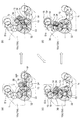
図2(a)〜(d)は、加工位置WPのワークWが給排位置TPへ移動する際のワークWの軌跡t1を示している。 Figure 2 (a) ~ (d) a work W processing position WP indicates the trajectory t 1 of the workpiece W as it moves to the sheet discharge position TP.
図2(a)に示す把持部15が加工位置WPにある場合には、遊星ギヤ34の軸がアーム旋回軸33と同じ高さとなり、支持アーム13と把持アーム14とが水平に互いに一直線状に延びている。そして、支持アーム13が反時計回りに回動し始めると、固定ギア32と噛合するアイドラギア36は支持アーム13とともに公転しながら反時計回りに自転し、アイドラギア36と噛合する遊星ギア34が軌跡t2に沿って時計回りに回動する。これにより、把持部15が加工位置WPから離れる際には、下方へと移動する。従って、把持部15が加工位置WPの上方を通らずに離れるので、上部に工具を配置した場合にも工具と干渉せずに移動することができる。
When the
また、図2(b)及び図2(c)に示すように、把持アーム14が旋回する途中では、把持アーム14と支持アーム13とが側面視で重なり合って、把持部15が固定ギア32の側方を通過するように旋回する。さらに、図2(d)に示す把持部15が給排位置TPに到達した状態では、支持アーム13と把持アーム14とが再び一直線状になる。従って、アーム13,14の旋回途中では、旋回アーム14が旋回する軌跡を支持アーム13が旋回する軌跡に重ね合わせることができる。これにより、両アーム13、14が旋回する軌跡の範囲を狭くすることができ、工作機械Mの他の機構を配置する上で自由度が向上する。また、加工位置WP及び給排位置TPでは、支持アーム13と把持アーム14が一直線状になるので、これらの位置でのストロークを十分に確保することができる。
Further, as shown in FIGS. 2B and 2C, while the
これにより、把持アーム14は、把持部15が加工位置WPより下方を通過して、加工位置WPと該加工位置WPより上方に配置された給排位置TPとの間を移動するように遊星運動する。
また、把持部15は、基台10にワークWの厚さよりわずかに広いすきまを隔てて固定された2枚のガイド板10c、10dの間を旋回するので、ワークWは把持部15の凹部内に収容されたままの状態で搬送可能である。
As a result, the
In addition, since the
シャトル機構50は、給排位置TPを備えて、アーム旋回軸33と平行に延び、ワークWを案内するシャトルガイド51と、エアシリンダ機構52によってシャトルガイド51内を水平移動可能なシャトル53と、を備える。
The
図3に示すように、シャトルガイド51は、ガイド板10c,10dを境に、互いに略左右対称な形状の搬入側シャトルガイド51aと搬出側シャトルガイド51bとからなる。搬入側シャトルガイド51aと搬出側シャトルガイド51bはともにワークWの直径よりわずかに大きな内径の貫通孔を有しており、ガイド板10c,10dに固定されている。ガイド板10c,10dにも同様に、ワークWの直径よりわずかに大きな内径の貫通孔を有しており、これら4つが一直線上に並んでいることにより、シャトル53の通路を形成している。また、シャトルガイド51、ガイド板10b、10cの全長にわたり、手前側にはシャトル53が通過するための切欠き51cを有する。さらに、搬入側シャトルガイド51aと搬出側シャトルガイド51bはワークW及びローダ40の把持部40aが上下方向に出入り可能なような形状を有する。
As shown in FIG. 3, the
シャトル53は、4枚の同形の仕切り板53aを有している。具体的には、仕切り板53aは、シャトルガイド51内に位置し、ワークWの外径と略等しい径の円弧状で上部にはローダ40の把持部40aとの干渉を避けるための切欠きを備えた本体部と、細長い基部とからなり、基部は前記切欠き51cから外部へ延びている。左側の2枚及び右側の2枚は、それぞれ基端部でスペーサ53bを介して結合されている。さらに中央の2枚は、後述のエアシリンダ装置のスライド部52a(より詳しくは、シリンダ固定部52bを貫通した右側の部分の端板52c。なお、図1で10bはシリンダ装置52を基台10に固定するブラケットである。)に固定される腕部53cを介して結合されている。スペーサ53bの厚さは、ワークWの幅よりわずかに大きく、ガイド板10c、10dの間の間隔と等しい。そして、左側の2枚の仕切り板53a間には搬入されたワークW(未加工ワーク)が、右側の2枚の仕切り板53a間には搬出されるワークW(加工済みのワーク)が収容される。さらに、シャトルガイド51とシャトル53との関係は、シャトル53の移動により、加工済みのワークの収容部が給排位置TPに位置したときには、未加工のワークの収容部は、ワークWをローダ40により搬入可能な搬入位置IPに位置し、未加工のワークの収容部が給排位置TPに位置したときには、加工済みのワークの収容部は、ワークWをローダ40により搬出可能な搬出位置OPに位置するような関係になっている。
The
このように構成されたワーク給排装置100では、前工程の装置から未加工のワークWがガントリローダ40によってシャトルガイド51の搬入位置IP(図1中、左側)に供給される。また、このとき給排位置TPには、把持アーム14の把持部15に収容された状態で加工済みのワークWが位置している。そして、ワークWは、エアシリンダ機構52によってシャトル53に押されてシャトルガイド51に沿って移動することにより、未加工のワークWが搬入位置IPから給排位置TPに待機している把持アーム14の把持部15の凹部内に運ばれ、同時に、加工済みのワークWが給排位置TPから搬出位置OPへ運ばれる。
In the workpiece supply /
把持アーム14を旋回することで、把持部15は、ワークWの中心が図2に示すようなワーク軌道t1を図2と逆の順に通過しながら遊星運動し、加工位置WPの下方から接近して、ワークWを加工位置WPへと運ぶ。この状態で、ワークWは把持部15から側面に設けられたバッキングプレート60等からなるワーク支持機構に支持されながら、加工位置WPの上方に配置された、図示しない砥石等の工具によって加工される。
By pivoting the gripping
加工済みのワークWは再度把持部15に収容された状態で上記と同様にワーク軌道t1によって給排位置TPへと移動する(図2に示す順)。このため、把持部15が加工位置WPを離れる際には、加工位置WPの下方を通る。次いで、再度シャトル53を搬出側(右端部)へ移動させることにより、今回加工した加工済みのワークWは搬出位置OPへ移される。その後、ガントリローダ40がこの加工済みのワークWを受け取り、後工程の装置へ搬出する。また、把持部15が加工位置WPにワークWを供給し、加工が行われている間に、先に加工済みのワークWの搬出位置OPでのガントリローダ40による搬出が行われ、さらに、シャトル機構50はシャトル53を左側に戻し、さらに次の未加工のワークWを供給する動作を完了させておく。そして、これらの工程を同様に繰り返す。
なお、ローダ40は、加工時間や搬送時間の条件により、搬入側と搬出側とに個別に設けてもよく、1台で両方の搬送を行うようにしてもよい。
Processed workpiece W is moved to the sheet discharge position TP in the same manner as described above by the work trajectory t 1 in a state of being accommodated in the
It should be noted that the
従って、本実施形態のワーク給排装置100によれば、動力伝達手段30が、モータ20と把持アーム14との間に設けられ、工具によってワークWを加工する加工位置WPとワークWを給排する給排位置TPとの間を把持部15が移動するようにモータ20の動力を把持アーム14に伝達する。これにより、供給位置と排出位置を同じ場所(給排位置)に設け、把持アーム14によるワークWの軌跡t1を1種類とすることで、給排装置TPへの搬送機構を含め、装置全体を小型化することができる。
Therefore, according to the workpiece feeding / discharging
また、把持アーム14は、その旋回中心を移動させながら旋回動作することで、自転及び公転を利用した遊星運動する。これにより、加工点近傍の配置の自由度をアップすることができ、加工刃具等の工具を上方に配置する場合であっても、加工刃具の退避動作が不要となり、効率的な加工サイクルを実現することができる
In addition, the
また、給排位置TPが加工位置WPより上方に配置されていることにより、前工程及び後工程との搬送を容易に行うことができるようになる。さらに、旋回アーム14が加工位置WPより下方を通過して遊星運動することによって、加工位置WP近傍のワーク支持機構や刃具等の配置の自由度を上げられる。
In addition, since the supply / discharge position TP is disposed above the processing position WP, it is possible to easily carry the pre-process and the post-process. Furthermore, the
さらに、動力伝達手段30は、モータ20駆動手段によって回転するアーム旋回軸33と同軸上に取付けられた固定ギア32と、把持アーム14の支点部に取り付けられた遊星ギア34と、固定ギア32と遊星ギア34の両方に噛合するアイドラギア36と、アーム旋回軸33に旋回可能に取り付けられ、遊星ギア34とアイドラギア36を軸支する支持アーム13と、を有し、把持アーム14は、把持部15が固定ギア32の側方を通過するようにして加工位置WPと給排位置TPとの間を移動するように遊星運動する。これにより、両アーム13、14が旋回する軌跡の範囲を狭くすることができ、工作機械Mの他の機構を配置する上で自由度が向上する。
また、シャトル53の往復移動と把持アーム14の旋回動作との連携により、アイドルタイムの短縮ができる。
Further, the power transmission means 30 includes a fixed
Further, the idle time can be shortened by cooperation between the reciprocating movement of the
尚、本発明は、前述した実施形態に限定されるものではなく、適宜、変形、改良、等が可能である。
例えば、本実施形態においては、ワークは、軸受軌道輪等の円筒状ワークとして説明したが、これに限定されるものではなく、把持部の把持機構を変形することにより、種々のワークに対応可能である。
また、リング状ワークを加工する機械は、研磨、切削、研削等、任意の工作機械であってもよい。
In addition, this invention is not limited to embodiment mentioned above, A deformation | transformation, improvement, etc. are possible suitably.
For example, in the present embodiment, the workpiece has been described as a cylindrical workpiece such as a bearing race ring. However, the workpiece is not limited to this, and can be applied to various workpieces by deforming the holding mechanism of the holding portion. It is.
Further, the machine that processes the ring-shaped workpiece may be any machine tool such as polishing, cutting, and grinding.
100 ワーク給排装置
W ワーク
WP 加工位置
TP 給排位置
13 支持アーム
14 把持アーム
15 把持部
20 モータ(駆動手段)
24 ベルト
26 駆動プーリ
28 従動プーリ
29 アイドラプーリ
30 動力伝達手段
32 固定ギア
33 アーム旋回軸
34 遊星ギア
36 アイドラギア
40 ガントリローダ(搬送機構)
100 Workpiece supply / discharge device W Workpiece WP Processing position TP Supply /
24 belt 26 driving
Claims (3)
前記駆動手段と前記把持アームとの間に設けられ、工具によって前記ワークを加工する加工位置と前記ワークを給排する給排位置との間を前記把持部が移動するように前記駆動手段の動力を前記把持アームに伝達する動力伝達手段と、
を有し、
前記把持アームは、その旋回中心を移動させながら旋回動作することで、自転及び公転を利用した遊星運動することを特徴とするワーク給排装置。 A gripping arm that has a gripping part capable of holding a workpiece at the tip and that pivots by the power of the driving means;
Power of the driving means provided between the driving means and the gripping arm so that the gripping part moves between a processing position where the workpiece is processed by a tool and a supply / discharge position where the work is supplied / discharged. Power transmission means for transmitting to the grip arm;
Have
The work feeding / discharging device, wherein the gripping arm performs a planetary motion using rotation and revolution by rotating while moving the center of rotation.
前記把持アームは、前記把持部が前記加工位置より下方を通過するように遊星運動することを特徴とする請求項1に記載のワーク給排装置。 The supply / discharge position is disposed above the processing position,
The workpiece feeding / discharging device according to claim 1, wherein the gripping arm performs a planetary motion so that the gripping portion passes below the processing position.
前記駆動手段によって回転するアーム旋回軸と同軸上に取付けられた固定ギアと、
前記把持アームの支点部に取り付けられた遊星ギアと、
前記固定ギアと前記遊星ギアの両方に噛合するアイドラギアと、
前記アーム旋回軸に旋回可能に取り付けられ、前記遊星ギアと前記アイドラギアを軸支する支持アームと、
を有し、
前記把持アームは、前記把持部が前記固定ギアの側方を通過して前記加工位置と前記給排位置との間を移動するように遊星運動することを特徴とする請求項1または2に記載のワーク給排装置。 The power transmission means is
A fixed gear coaxially attached to an arm pivot that is rotated by the drive means;
A planetary gear attached to a fulcrum portion of the gripping arm;
An idler gear meshing with both the fixed gear and the planetary gear;
A support arm pivotally attached to the arm pivot shaft, and supporting the planetary gear and the idler gear;
Have
3. The planetary movement according to claim 1, wherein the gripping arm performs a planetary motion so that the gripping part passes between the fixed gear and moves between the processing position and the supply / discharge position. Work supply / discharge device.
Priority Applications (1)
| Application Number | Priority Date | Filing Date | Title |
|---|---|---|---|
| JP2009039312A JP5287334B2 (en) | 2009-02-23 | 2009-02-23 | Work supply / discharge device |
Applications Claiming Priority (1)
| Application Number | Priority Date | Filing Date | Title |
|---|---|---|---|
| JP2009039312A JP5287334B2 (en) | 2009-02-23 | 2009-02-23 | Work supply / discharge device |
Publications (3)
| Publication Number | Publication Date |
|---|---|
| JP2010194624A JP2010194624A (en) | 2010-09-09 |
| JP2010194624A5 JP2010194624A5 (en) | 2011-11-24 |
| JP5287334B2 true JP5287334B2 (en) | 2013-09-11 |
Family
ID=42819900
Family Applications (1)
| Application Number | Title | Priority Date | Filing Date |
|---|---|---|---|
| JP2009039312A Active JP5287334B2 (en) | 2009-02-23 | 2009-02-23 | Work supply / discharge device |
Country Status (1)
| Country | Link |
|---|---|
| JP (1) | JP5287334B2 (en) |
Family Cites Families (6)
| Publication number | Priority date | Publication date | Assignee | Title |
|---|---|---|---|---|
| JPS6125745A (en) * | 1984-07-13 | 1986-02-04 | Hitachi Seiki Co Ltd | Carrying object interchange apparatus for machine tool |
| JP3091068B2 (en) * | 1993-11-04 | 2000-09-25 | ワイケイケイ株式会社 | Machined surface indexing device for end processing machine of long profile material |
| JP3225829B2 (en) * | 1996-02-27 | 2001-11-05 | トヨタ自動車株式会社 | Article transfer device |
| JP3861494B2 (en) * | 1999-02-01 | 2006-12-20 | 村田機械株式会社 | Work payout device |
| JP3926583B2 (en) * | 2001-05-21 | 2007-06-06 | Ntn株式会社 | Loading device |
| JP2003311575A (en) * | 2002-04-17 | 2003-11-05 | Seiko Instruments Inc | Workpiece supply/discharge device |
-
2009
- 2009-02-23 JP JP2009039312A patent/JP5287334B2/en active Active
Also Published As
| Publication number | Publication date |
|---|---|
| JP2010194624A (en) | 2010-09-09 |
Similar Documents
| Publication | Publication Date | Title |
|---|---|---|
| JP5835139B2 (en) | Rotary processing machine and rotary processing method | |
| KR102448070B1 (en) | banding machine | |
| JP5741531B2 (en) | Rotary processing machine and rotary processing method | |
| JP2008260120A (en) | Handling manipulator device | |
| US11331736B2 (en) | Moving system and gear-cutting machine | |
| JP5696771B2 (en) | Rotary processing machine and rotary processing method | |
| JP2008183705A (en) | Workpiece processing device | |
| KR20130061116A (en) | Machine tool for treating wavy workpieces | |
| JP2018130771A (en) | Transportation tool | |
| JP2009000794A (en) | Double head surface grinding machine | |
| JP5287334B2 (en) | Work supply / discharge device | |
| JP2019089155A (en) | Work-piece exchange device and machine tool | |
| JP5125129B2 (en) | Work supply / discharge device | |
| WO2016148061A1 (en) | Gear chamfering device and gear processing machine equipped with said gear chamfering device | |
| JP2015074038A (en) | Oscillating table device and circular arc machining device | |
| JP6735354B2 (en) | Machine tools and processing machine lines | |
| JP6728373B2 (en) | Automatic work transfer machine | |
| JP2005066762A (en) | Carrier robot | |
| CN112124888A (en) | Transfer system, transport system and method for removing and pushing on sleeve-shaped workpieces | |
| JP4978228B2 (en) | Work supply / discharge device | |
| JP2019126864A (en) | Transfer tool and robot | |
| JP6677366B1 (en) | Work changer, work transfer device, processing device, method for manufacturing ring bearing, method for manufacturing machine, method for manufacturing vehicle | |
| JP6447229B2 (en) | Transport device | |
| WO2013118587A1 (en) | Shot processing apparatus and shot processing method | |
| JP4967684B2 (en) | Workpiece supply / discharge device and work supply / discharge method |
Legal Events
| Date | Code | Title | Description |
|---|---|---|---|
| A521 | Written amendment |
Free format text: JAPANESE INTERMEDIATE CODE: A523 Effective date: 20111011 |
|
| A621 | Written request for application examination |
Free format text: JAPANESE INTERMEDIATE CODE: A621 Effective date: 20111011 |
|
| A977 | Report on retrieval |
Free format text: JAPANESE INTERMEDIATE CODE: A971007 Effective date: 20130130 |
|
| TRDD | Decision of grant or rejection written | ||
| A01 | Written decision to grant a patent or to grant a registration (utility model) |
Free format text: JAPANESE INTERMEDIATE CODE: A01 Effective date: 20130507 |
|
| A61 | First payment of annual fees (during grant procedure) |
Free format text: JAPANESE INTERMEDIATE CODE: A61 Effective date: 20130520 |
|
| R150 | Certificate of patent or registration of utility model |
Ref document number: 5287334 Country of ref document: JP Free format text: JAPANESE INTERMEDIATE CODE: R150 |