JP5285933B2 - Concrete member and manufacturing method thereof, synthetic segment and manufacturing method thereof - Google Patents
Concrete member and manufacturing method thereof, synthetic segment and manufacturing method thereof Download PDFInfo
- Publication number
- JP5285933B2 JP5285933B2 JP2008060093A JP2008060093A JP5285933B2 JP 5285933 B2 JP5285933 B2 JP 5285933B2 JP 2008060093 A JP2008060093 A JP 2008060093A JP 2008060093 A JP2008060093 A JP 2008060093A JP 5285933 B2 JP5285933 B2 JP 5285933B2
- Authority
- JP
- Japan
- Prior art keywords
- main steel
- compression transmission
- steel material
- wedge
- main
- Prior art date
- Legal status (The legal status is an assumption and is not a legal conclusion. Google has not performed a legal analysis and makes no representation as to the accuracy of the status listed.)
- Active
Links
Images


Description
本発明は、例えば掘削穴の内面に沿って周方向及び軸方向に複数連結されることで筒状壁体を構成するセグメント、具体的にはスチール等の構造部材とコンクリートとを複合使用した合成セグメントとその製造方法、そしてこれら合成セグメントを含むコンクリート部材とその製造方法に関する。 The present invention is, for example, a composite that uses a combination of a segment that forms a cylindrical wall body by being connected in a circumferential direction and an axial direction along the inner surface of a drilling hole, specifically, a structural member such as steel and concrete. The present invention relates to a segment, a manufacturing method thereof, a concrete member including these synthetic segments, and a manufacturing method thereof.
現在、トンネルの構築に用いられる方法としては、掘削穴の内面側に円弧版状のセグメントを複数連結して筒状壁体を構築する、いわゆるシールド工法が一般的である。このシールド工法に用いられるセグメントとしては、例えばコンクリート製、鋼製あるいは鋼材とコンクリートとを複合使用した合成セグメントが知られており、特許文献1に記載のものは、合成セグメントの一例である。 At present, a so-called shield method is generally used as a method for constructing a tunnel, in which a cylindrical wall body is constructed by connecting a plurality of arc-shaped segments on the inner surface side of an excavation hole. As a segment used in this shield method, for example, a composite segment made of concrete, steel, or a composite use of steel and concrete is known, and the one described in Patent Document 1 is an example of a composite segment.
この特許文献1に記載されている合成セグメントは、2つの主桁と2つの継手板とスキンプレートを有し、開口端が形成された円弧版状を為しており、当該2つの主桁間に更に少なくとも1本の略H状のずれ止めを配置し、しかる後に当該開口端より中詰めコンクリートを充填したものであり、割れや欠けの生じやすいセグメントの内外周面の四辺の角部を含め、合成セグメントの枠体の大部分を構造部材で構成することにより、高い強度を発揮している。
また、合成セグメントの枠体の大部分が構造部材で覆われているため、地山側からの漏水に対する止水性についても一定の配慮が為されている。
また、他の合成セグメントとして、内部にH型の鋼材を含むと共にコンクリートを充填して外表面をコンクリートで被覆するようにしたものも提案されている。この種の合成セグメントでは上述した特許文献1に記載されたものと比較して鋼材が外部に露出しないために鋼材の腐食を防ぎセグメントの耐久性を向上できる。この合成セグメントでは、外周面がコンクリートで被覆されているため、シール溝もコンクリートで形成されている。
そして、この合成セグメントのリング状の継手面同士を継手で連結してセグメントリングを形成する。
In addition, since most of the frame of the composite segment is covered with a structural member, certain consideration is given to water-stopping against water leakage from the natural ground side.
Another synthetic segment has been proposed which includes an H-shaped steel material inside and is filled with concrete so that the outer surface is covered with concrete. In this type of synthetic segment, since the steel material is not exposed to the outside as compared with that described in Patent Document 1 described above, the corrosion of the steel material can be prevented and the durability of the segment can be improved. In this synthetic segment, since the outer peripheral surface is covered with concrete, the seal groove is also formed of concrete.
And the ring-shaped joint surfaces of this synthetic segment are connected with a joint to form a segment ring.
ところが近年、セグメントには高強度化の要求、止水性の要求に加え、薄型化とコストダウンの要請が高まってきている。
しかし特許文献1に記載の合成セグメントのように、開口部以外の周囲全てを構造部材(鋼材)で覆っているものにあっては、所定の強度を得るために合成セグメント自身の厚みが増大し、また重量も嵩む傾向にあった。更に、使用する鋼材量が多いため、強度及び止水性は満足できてもコストダウンの要請に応えることは困難であった。
また、後者の合成セグメントでは、鋼材からなる構造部材をコンクリートで被覆しているため、セグメントリングをトンネルの軸方向に順次連結してトンネルを構築した場合、土圧等の荷重がセグメントリングを形成する各合成セグメントの継手面同士に圧縮力として印加されることになる。この場合、シール部材を装着するシール溝がコンクリート製であるため、過度の圧縮力でシール溝から内外周面にかけてクラックが入る等、圧壊され易いという欠点がある。これを防いで強度を確保するためには、シール溝を合成セグメントの厚み方向中央側に形成しなければならず、厚みが増大して合成セグメントを薄型化できない欠点が生じる。そのため、高強度化と薄型化とコストダウンを同時に達成することができなかった。
However, in recent years, in addition to demands for higher strength and water-stopping requirements for segments, there are increasing demands for thickness reduction and cost reduction.
However, as in the synthetic segment described in Patent Document 1, in the case where the entire periphery other than the opening is covered with a structural member (steel material), the thickness of the synthetic segment itself increases to obtain a predetermined strength. Also, the weight tended to increase. Furthermore, since the amount of steel used is large, it is difficult to meet the demand for cost reduction even if the strength and water stoppage can be satisfied.
In the latter synthetic segment, steel structural members are covered with concrete, so when a tunnel is constructed by sequentially connecting segment rings in the axial direction of the tunnel, a load such as earth pressure forms the segment ring. The compression force is applied between the joint surfaces of each composite segment. In this case, since the seal groove on which the seal member is mounted is made of concrete, there is a drawback that cracks tend to occur from the seal groove to the inner and outer peripheral surfaces with an excessive compressive force. In order to prevent this and secure strength, the seal groove must be formed in the center of the synthetic segment in the thickness direction, resulting in a drawback that the synthetic segment cannot be thinned due to an increase in thickness. For this reason, it has been impossible to achieve high strength, thinning, and cost reduction at the same time.
本発明は、このような実情に鑑みてなされたものであって、高強度を維持して薄型化と低コスト化を達成したコンクリート部材とその製造方法、合成セグメントとその製造方法を提供することを目的とするものである。 The present invention has been made in view of such a situation, and provides a concrete member, a manufacturing method thereof, a synthetic segment, and a manufacturing method thereof, which have achieved high thickness and reduced thickness and cost. It is intended.
本発明によるコンクリート部材は、対向する二つの端面を形成していて内部に鋼材を配設したコンクリート部材であって、対向する端面にそれぞれ露出する圧縮伝達材と、対向する圧縮伝達材の間に延在している主鋼材と、主鋼材の一方または両方の端部と圧縮伝達材との間に介在するくさび材とを備え、前記くさび部材を介して前記圧縮伝達材と主鋼材とに圧縮力を作用させることを特徴とする。
本発明によれば、コンクリート部材の対向する端面に圧縮力がかかった場合、圧縮伝達材から主鋼材に伝達して分散させることができるので、端面が圧縮力で圧壊されることはない。しかも、主鋼材とその一端または両端の圧縮伝達材との間にくさび材を圧入することで各部材を互いに押圧した密接状態に保持することができるので、形状や寸法が相違するコンクリート部材であっても主鋼材や圧縮伝達材に同一形状のものを採用してくさび材で寸法や内部の圧縮力を調整することができる。そのため、コンクリート部材は高強度で薄型化を図ることができ、外形寸法に関わらず同一鋼材を使用することで低コストを達成できる。
The concrete member according to the present invention is a concrete member in which two opposing end surfaces are formed and steel is disposed therein, and between the compression transmission material exposed on the opposite end surface and the opposing compression transmission material. An extended main steel material, and a wedge material interposed between one or both ends of the main steel material and the compression transmission material, and compressed to the compression transmission material and the main steel material via the wedge member It is characterized by acting force.
According to the present invention, when a compressive force is applied to the opposing end surfaces of the concrete member, the end surface is not crushed by the compressive force because it can be transmitted from the compression transmission material to the main steel material and dispersed. Moreover, since the wedge material is press-fitted between the main steel material and the compression transmission material at one end or both ends thereof, the members can be held in close contact with each other, so that they are concrete members having different shapes and dimensions. However, it is possible to adjust the dimensions and internal compression force with a rust material by adopting the same shape for the main steel material and the compression transmission material. Therefore, the concrete member can be thinned with high strength, and low cost can be achieved by using the same steel material regardless of the external dimensions.
また、圧縮伝達材はシール溝を設けたシール部であってもよい。
圧縮伝達材によって外部からの圧縮力等の荷重を受けると共にシール溝にシール部材を配設できる。
また、くさび材は主鋼材の端部と圧縮伝達材との間に配設されていて、対向する一対の端面にそれぞれ露出する圧縮伝達材は互いに非平行に配設されていてもよい。
主鋼材と圧縮伝達材の間に圧入するくさび材によって両端面における圧縮伝達材を非平行に姿勢や長さを調整して配設できる。
また、くさび材は主鋼材の端部と圧縮伝達材との間に互いに逆方向に複数介在していて、対向する一対の端面にそれぞれ露出する圧縮伝達材は互いに略平行に配設されていてもよい。
主鋼材と圧縮伝達材の間に圧入するくさび材によって両端面における圧縮伝達材を平行となるように姿勢や長さを調整して配設できる。
The compression transmission material may be a seal portion provided with a seal groove.
It is possible to receive a load such as a compressive force from the outside by the compression transmission material and arrange the seal member in the seal groove.
Further, the wedge material may be disposed between the end portion of the main steel material and the compression transmission material, and the compression transmission materials exposed to the pair of opposed end surfaces may be disposed non-parallel to each other.
The wedge transmission material press-fitted between the main steel material and the compression transmission material allows the compression transmission material on both end surfaces to be arranged in a non-parallel manner with the posture and length adjusted.
Further, a plurality of wedge members are interposed in opposite directions between the end portion of the main steel member and the compression transmission member, and the compression transmission members exposed on the pair of opposed end surfaces are arranged substantially parallel to each other. Also good.
A wedge material press-fitted between the main steel material and the compression transmission material can be arranged with its posture and length adjusted so that the compression transmission material on both end faces is parallel.
また、主鋼材は、端面に交差する外周面に沿って形成されている第一主鋼材と、外周面に対向する内周面に沿って形成されている第二主鋼材とで構成され、圧縮伝達材は一対の端面の第一主鋼材及び第二主鋼材の端部に対向してそれぞれ設けられた第一圧縮伝達材及び第二圧縮伝達材とを備え、くさび材は、第一主鋼材及び第一圧縮伝達材の間に介在する第一くさび材と、第二主鋼材及び第二圧縮伝達材の間に介在する第二くさび材とを備えてなることが好ましい。
本発明によれば、外部からの圧縮力を受けて内部に伝達する第一圧縮伝達材及び第二圧縮伝達材と第一主鋼材及び第二主鋼材とを二層に構成したから、大きな圧縮力が外部からかかったとしても確実に第一主鋼材及び第二主鋼材にそれぞれ伝達して分散させることができ、圧縮力による端面の圧壊を確実に防止できる。
The main steel material is composed of a first main steel material formed along the outer peripheral surface intersecting the end surface and a second main steel material formed along the inner peripheral surface facing the outer peripheral surface, and is compressed. The transmission material includes a first compression transmission material and a second compression transmission material provided to face the ends of the first main steel material and the second main steel material of the pair of end faces, respectively, and the wedge material is the first main steel material And a first wedge material interposed between the first compression transmission material and a second wedge material interposed between the second main steel material and the second compression transmission material.
According to the present invention, since the first compression transmission material and the second compression transmission material that transmit to the inside by receiving the compression force from the outside, the first main steel material and the second main steel material are configured in two layers, Even if force is applied from the outside, it can be reliably transmitted and dispersed to the first main steel material and the second main steel material, respectively, and the end face can be reliably prevented from being collapsed by the compressive force.
本発明による合成セグメントは、周方向及び軸方向の端面をなす継手面及び主桁面で複数連結されることで略筒状壁体を構築する円弧板状の合成セグメントであって、対向する一対の継手面にそれぞれ露出する圧縮伝達材と、対向する一対の圧縮伝達材の間に延在している主鋼材と、主鋼材の一方または両方の端部と圧縮伝達材との間に介在するくさび材とを備え、前記くさび部材を介して前記圧縮伝達材と主鋼材とに圧縮力を作用させることを特徴とする。
本発明によれば、合成セグメントの端面に土圧等によって圧縮力がかかった場合、圧縮伝達材から直接またはくさび材を介して確実に主鋼材に伝達して分散させることができるので、端面が圧縮力で圧壊されることはない。しかも、主鋼材とその一端または両端の圧縮伝達材との間にくさび材を圧入することで各部材を互いに押圧した密接状態に保持することができるので、合成セグメントの形状が相違するものであっても主鋼材や圧縮伝達材に同一形状のものを採用して、くさび材で寸法や内部の圧縮力を調整することができる。そのため、合成セグメントは高強度で薄型化を図ることができ、外形寸法に関わらず同一鋼材を使用することで低コストを達成できる。
The composite segment according to the present invention is an arcuate plate-like composite segment that forms a substantially cylindrical wall body by connecting a plurality of joint surfaces and main girder surfaces that form end faces in the circumferential direction and the axial direction. Between the compression transmission material exposed on the joint surface of the steel plate, the main steel material extending between the pair of opposed compression transmission materials, and one or both ends of the main steel material and the compression transmission material A wedge member, and a compression force is applied to the compression transmission member and the main steel member via the wedge member.
According to the present invention, when a compressive force is applied to the end face of the composite segment due to earth pressure or the like, it can be reliably transmitted directly to the main steel material from the compression transmission material or via the wedge material, so that the end face can be dispersed. It is not crushed by the compressive force. Moreover, since the wedge members are press-fitted between the main steel material and the compression transmission material at one end or both ends thereof, the members can be held in close contact with each other, so the shapes of the composite segments are different. However, the same shape can be adopted for the main steel material and the compression transmission material, and the dimensions and the internal compression force can be adjusted with the wedge material. Therefore, the synthetic segment can be thinned with high strength, and low cost can be achieved by using the same steel material regardless of the external dimensions.
また、主鋼材は、端面に交差する略円弧状をなす外周面に沿って形成されている第一主鋼材と、外周面に対向する略円弧状をなす内周面に沿って形成されている第二主鋼材とで構成され、圧縮伝達材は、一対の端面において第一主鋼材及び第二主鋼材の両端部に対向してそれぞれ設けられた第一圧縮伝達材と第二圧縮伝達材とを備え、くさび材は、第一主鋼材及び第一圧縮伝達材の間に介在する第一くさび材と、第二主鋼材及び第二圧縮伝達材の間に介在する第二くさび材とを備え、第二主鋼材は内周面の内側に位置してコンクリートで被覆されていることが好ましい。
本発明による合成セグメントでは、構造材が第一主鋼材と第二主鋼材を含む二層構造で構成されているため、外部から働く圧縮力を第一圧縮伝達材と第二圧縮伝達材で受けて、直接またはくさび材を介して第一主鋼材と第二主鋼材に伝達されて分散されるため、より高い圧縮力が働いても二層で構成された第一主鋼材と第二主鋼材に確実に伝達されて分散させることができ、端面の圧壊を防止できる。
また、第一圧縮伝達材にはそれぞれシール溝が設けられていてもよく、シール溝を有するシール部を圧縮伝達材とすることで、部品数を低減して構成を簡略化できてコストを低減できる。
The main steel material is formed along a first main steel material that is formed along an outer peripheral surface that forms a substantially arc shape that intersects the end surface, and an inner peripheral surface that forms a substantially arc shape that faces the outer peripheral surface. The first main transmission material and the second main transmission material, the first transmission transmission material and the second compression transmission material respectively provided opposite to both ends of the first main steel material and the second main steel material at the pair of end surfaces. The wedge material includes a first wedge material interposed between the first main steel material and the first compression transmission material, and a second wedge material interposed between the second main steel material and the second compression transmission material. The second main steel material is preferably positioned on the inner peripheral surface and covered with concrete.
In the composite segment according to the present invention, since the structural material is composed of a two-layer structure including the first main steel material and the second main steel material, the first compression transmission material and the second compression transmission material receive the compressive force acting from the outside. The first main steel material and the second main steel material which are composed of two layers even if higher compressive force is applied, because it is transmitted to the first main steel material and the second main steel material and dispersed directly or via a wedge material Can be reliably transmitted and dispersed, and the end face can be prevented from being crushed.
In addition, each first compression transmission material may be provided with a seal groove. By using a seal portion having a seal groove as the compression transmission material, the number of parts can be reduced, the configuration can be simplified, and the cost can be reduced. it can.
本発明によるコンクリート部材の製造方法は、対向する二つの端面を有していて内部に鋼材を配設したコンクリート部材を型枠で製造する製造方法であって、型枠における、コンクリート部材の対向する一対の端面の位置にそれぞれ圧縮伝達材を型枠に固定させると共に圧縮伝達材間に主鋼材を配設し、主鋼材の一方または両方の端部と圧縮伝達材との間にくさび材を打ち込んで主鋼材と圧縮伝達材との間に嵌合させて前記くさび部材を介して前記圧縮伝達材と主鋼材とに圧縮力を作用させ、硬化前のコンクリート材を型枠内に流し込んでコンクリート部材を製造するようにしたことを特徴とする。
本発明によれば、コンクリート部材の製造に際し、型枠に固定した圧縮伝達材の間に主鋼材を配設して、くさび材を打ち込むことで互いに密着させ、主鋼材の寸法誤差を調整すると共に両側の圧縮伝達材を型枠に密着させることができて外部からの圧縮力を確実に主鋼材に伝達できるコンクリート部材を製造できる。
A method for producing a concrete member according to the present invention is a method for producing a concrete member having two opposing end faces and having steel material disposed therein, using a mold, and the concrete member faces the mold. The compression transmission material is fixed to the mold at the position of the pair of end faces, and the main steel material is disposed between the compression transmission materials, and the wedge material is driven between one or both ends of the main steel material and the compression transmission material. In this case, it is fitted between the main steel material and the compression transmission material , and a compressive force is applied to the compression transmission material and the main steel material via the wedge member, and the concrete material before hardening is poured into the formwork into the concrete member. It is characterized in that it is manufactured.
According to the present invention, when manufacturing a concrete member, the main steel material is disposed between the compression transmission materials fixed to the mold, and the wedge material is driven into close contact with each other to adjust the dimensional error of the main steel material. It is possible to manufacture a concrete member capable of bringing the compression transmission material on both sides into close contact with the formwork and reliably transmitting the compression force from the outside to the main steel material.
本発明による合成セグメントの製造方法は、対向する二つの端面を有していて内部に鋼材を配設した合成セグメントを型枠で製造する製造方法であって、型枠における、合成セグメントの対向する一対の端面の位置にそれぞれ圧縮伝達材を型枠に固定させると共に圧縮伝達材間に主鋼材を配設し、主鋼材の一方または両方の端部と圧縮伝達材との間にくさび材を打ち込んで主鋼材と圧縮伝達材との間に嵌合させて前記くさび部材を介して前記圧縮伝達材と主鋼材とに圧縮力を作用させ、次いで硬化前のコンクリート材を型枠内に流し込んで合成セグメントを製造するようにしたことを特徴とする。
本発明によれば、型枠に固定した圧縮伝達材の間に主鋼材を配設して、くさび材を打ち込むことで各鋼材を互いに密着させ、主鋼材の寸法誤差を調整すると共に両側の圧縮伝達材を型枠に密着させることができて外部からの圧縮力を確実に主鋼材に伝達できる合成セグメントを製造できる。
A synthetic segment manufacturing method according to the present invention is a manufacturing method for manufacturing a composite segment having two opposite end faces and having a steel material disposed therein by using a mold, wherein the composite segment faces each other in the mold The compression transmission material is fixed to the mold at the position of the pair of end faces, and the main steel material is disposed between the compression transmission materials, and the wedge material is driven between one or both ends of the main steel material and the compression transmission material. In this way, the main steel material is fitted between the compression transmission material and a compression force is applied to the compression transmission material and the main steel material via the wedge member, and then the uncured concrete material is poured into the mold and synthesized. It is characterized in that a segment is manufactured.
According to the present invention, the main steel material is disposed between the compression transmission materials fixed to the mold, and the steel materials are brought into close contact with each other by driving the wedge material, thereby adjusting the dimensional error of the main steel material and compressing the both sides. It is possible to manufacture a synthetic segment that can bring the transmission material into close contact with the formwork and can reliably transmit the external compression force to the main steel material.
本発明に係るコンクリート部材及び合成セグメントによれば、対向する端面に露出する圧縮伝達材と主鋼材との間にくさび材が嵌合されて、これら鋼材が一体に圧接された状態になるため、対向する端面にかかる圧縮力を端面に露出する圧縮伝達材から直接またはくさび材を介して主鋼材に伝達させて分散させることができ、しかも、これらが構造材として外部からかかる圧縮力を受け止めることができる。そのため、コンクリート部材や合成セグメントに過大な圧縮力がかかることがなく、高強度で端面の圧壊を防止できると共に薄型化できて低コスト化できる。 According to the concrete member and the composite segment according to the present invention, the wedge material is fitted between the compression transmission material and the main steel material exposed at the opposing end surfaces, and these steel materials are in a state of being integrally pressed, The compressive force applied to the opposing end faces can be transferred directly from the compression transmission material exposed on the end faces to the main steel material via the wedge material, and these can receive the compressive force applied from the outside as a structural material. Can do. Therefore, an excessive compressive force is not applied to the concrete member or the composite segment, and the end face can be prevented from being crushed with high strength, and the thickness can be reduced and the cost can be reduced.
また、本発明に係るコンクリート部材及び合成セグメントの製造方法によれば、型枠内部に主鋼材を配設すると共に、主鋼材の端部と型枠に固着した圧縮伝達材との間にくさび材を打ち込むことで、圧縮伝達材とくさび材と主鋼材を互いに圧接して高い密着性を確保できると共に圧縮伝達材を型枠に隙間なく密着でき、外部からの圧縮力等の荷重をこれら構造材によって確実に受けることができる。そして、型枠内にコンクリートを打設することで高強度で薄型化したコンクリート部材や合成セグメントを低コストで製造できる。 Further, according to the concrete member and the synthetic segment manufacturing method according to the present invention, the main steel material is disposed inside the mold, and the wedge material is disposed between the end of the main steel material and the compression transmission material fixed to the mold. The compression transmission material, the wedge material and the main steel material can be pressed against each other to ensure high adhesion, and the compression transmission material can be closely adhered to the mold frame, and external loads such as compressive force can be applied to these structural materials. Can be surely received. And the concrete member and synthetic | combination segment thinned with high intensity | strength by placing concrete in a formwork can be manufactured at low cost.
以下、本発明の実施形態を添付図面に基づいて説明する。
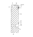
図1乃至図10は本発明による合成セグメントの第一の実施形態を示すものである。図1は合成セグメントの一部破断斜視図、図2は下方から見た斜視図、図3は図2のA−A線断面図、図4はB−B線断面図、図5はC−C線断面図、図6は継手面の部分断面図、図7は図6のD−D線断面図、図8は図7のE−E線断面図、図9は本実施形態による合成セグメントの製造方法を示す図、図10は主シール部の正面図と断面図である。
図1及び図2において、本実施形態による合成セグメント1は略円弧板形状を有していてコンクリート内部に後述する鋼材が構造材として配設された平面視略長方形状の構成を有している。この合成セグメント1は地山側の外周面2にはスキンプレート3が被覆形成され、外周面2に対向する内空側の内周面4はコンクリートcで形成されている。合成セグメント1の外周面2と内周面4に挟まれた四つの側面のうち長手方向に延びる対向する二面が主桁面5とされ、短手方向に延びる対向する二面が継手面6とされている。なお、便宜上、継手面6の一方を継手面6aとし、他方を継手面6bとする。
主桁面5の一方には例えばピン等の雄継手8が装着され、他方にはピンと嵌合する凹部等の雌継手9が設けられており、リング継手を構成する。継手面6には互いに嵌合する水平コッタ等の継手部10がセグメント継手として設けられている。
Hereinafter, embodiments of the present invention will be described with reference to the accompanying drawings.
1 to 10 show a first embodiment of a synthetic segment according to the present invention. 1 is a partially broken perspective view of a synthetic segment, FIG. 2 is a perspective view seen from below, FIG. 3 is a cross-sectional view taken along line AA in FIG. 2, FIG. 4 is a cross-sectional view taken along line BB, and FIG. 6 is a partial cross-sectional view of the joint surface, FIG. 7 is a cross-sectional view taken along the line DD of FIG. 6, FIG. 8 is a cross-sectional view taken along the line EE of FIG. FIG. 10 is a front view and a cross-sectional view of the main seal portion.
1 and 2, the composite segment 1 according to the present embodiment has a substantially arcuate plate shape, and has a substantially rectangular configuration in plan view in which a steel material to be described later is disposed as a structural material inside the concrete. . The composite segment 1 has a
For example, a male joint 8 such as a pin is mounted on one side of the
合成セグメント1の外周面2には、図1及び図3に示すように、スキンプレート3の内側に当接して略板状の第一主鋼材12が一方の継手面6近傍から対向する他方の継手面6近傍まで円弧状に湾曲して延びている。合成セグメント1の内部には、第一主鋼材12に対向して第二主鋼材13が一方の継手面6近傍から対向する他方の継手面6近傍まで円弧状に湾曲して延びている。第二主鋼材13は内周面4の内側に位置してコンクリートcで被覆されている。なお、第一及び第二主鋼材12、13は同一材料、同一形状のものを使用してもよい。
第一主鋼材12と第二主鋼材13はその長手方向に所定間隔で配列された連結部材としての束材14によって連結されており、これを主鋼材15とする。そのため、主鋼材15は図3に示すように断面略H字形状とされ、継手面6の延在方向に沿って1または複数列(図では3列)間隔を置いて配列されている。なお、第一、第二主鋼材12,13は内面に長手方向に直交する凹溝が所定間隔で形成されており、打設されるコンクリートとの密着性を向上させている。
また、外周面2側では第一主鋼材12にスキンプレート3が水密溶接により溶接されている。また、第一及び第二主鋼材12,13の周囲には配力鉄筋や主鉄筋、補強鉄筋等が配設されている。
As shown in FIGS. 1 and 3, the outer
The first
On the outer
合成セグメント1の一方の継手面6aにおいて、外周面2に沿ってシール溝16を形成した帯状の鋼板からなる主シール部17が配設され、その後面には所定間隔で配列された第一主鋼材12の端部が当接している(図6参照)。主シール部17は第一圧縮伝達材を構成する。図4及び図6に示す他方の継手面6bにおいても、同様に外周面2に沿ってシール溝16を形成した主シール部17が配設され、その後面には第一主鋼材12の端部との間に第一くさび材18が圧入されて嵌合している。ここで、継手面6a,6bにおける主シール部17の一方を主シール部17aとし、他方を主シール部17bとする。
図7に示すように、第一くさび材18はテーパ状の板材または角材等で形成されており、2本の第一くさび材18が互いに逆方向から主シール部17bと第一主鋼材12の端部との間に圧入され、主シール部17bの延在方向に延びている。そのため、両側の継手面6a,6b間において、各シール溝16付きの主シール部17a、17bは第一主鋼材12と第一くさび材18を介して互いに押圧して支持されており、両側の継手面6a,6bはほぼ平行に配列されている。
On one
As shown in FIG. 7, the
また、第二主鋼材13の一方の端部は鋼材からなる第二圧縮伝達材20aの後端に当接しており、第二圧縮伝達材20aの先端は一方の継手面6aに露出している(図6参照)。図4及び図6に示す第二主鋼材13の他方の端部は、圧入嵌合された第二くさび材21を介して第二圧縮伝達材20bの後端に当接し、第二圧縮伝達材20bの先端は他方の継手面6bに露出している。
図8に示すように、第二くさび材21は第一くさび材18と同様にテーパ状に形成されており、2本の第二くさび材21が互いに逆方向から第二圧縮伝達材20bと第二主鋼材13の端部との間に圧入され、第一くさび材18の延在方向に沿って延びている。そのため、両側の継手面6a,6b間において、各第二圧縮伝達材20a、20bは第二主鋼材13と第二くさび材21を介して互いに押圧して支持されている。
そのため、トンネルのリング間セグメントを構築した状態で、土圧等で合成セグメント1の継手面6a,6b間に過大な圧縮力が作用したとしても、その荷重は主シール部17a、17b間の第一主鋼材12(及び第一くさび材18)と、第二圧縮伝達材20a、20b間の第二主鋼材13(及び第二くさび材21)とに分散させて負担することができ、コンクリートcで荷重を負担することを抑制できる。
One end of the second
As shown in FIG. 8, the
Therefore, even if an excessive compressive force acts between the
なお、継手面6a,6bにおいて、第二圧縮伝達材20a、20bの主シール部17側のコンクリート面には補助シール溝23が形成されている。また、主桁面5,5には、図5に示すように主シール部17のシール溝16と同一高さにシール溝25を形成したシール部26が固着され、補助シール溝23と同一高さのコンクリート面に同じく補助シール溝27が形成されている。
そのため、合成セグメント1の主桁面5と継手面6には、シール部26に設けたシール溝25と主シール部17に形成したシール溝16とに主シール材28が装着され、補助シール溝27,23には補助シール材29が装着されている。
In addition, in the
Therefore, the
本実施形態による合成セグメント1は上述の構成を備えており、次にその製造方法を図9を中心に説明する。
図9(a)、(b)、(c)は、いわゆる山打ちのコンクリート打設方法による合成セグメント1の製造工程を示したものである。図9(a)に示すように、この製造方法では、外周面2のスキンプレート3を上側に、内周面4を下側にした状態で、主桁面5の長手方向の略中央部を最も高い位置となる姿勢で合成セグメント1を製造するための型枠32が用いられる。
型枠32は、合成セグメント1の内周面4を円弧形状に形成するように塞ぐ底盤部32aと、継手面6a、6b及び主桁面5を形成するように塞ぐ側板部32bとから構成され、スキンプレート3が配置される外周面2に開口部32cが形成されている。この開口部32cがコンクリートcの充填口となる。なお、開口部32cは外周面2の中央頂部に開口として形成してもよい。
The synthetic segment 1 according to the present embodiment has the above-described configuration, and the manufacturing method thereof will be described with reference to FIG.
FIGS. 9A, 9B, and 9C show the manufacturing process of the synthetic segment 1 by the so-called mountain placing concrete placing method. As shown in FIG. 9A, in this manufacturing method, a substantially central portion in the longitudinal direction of the
The
合成セグメント1の製造方法として、まず、図9(a)に示す型枠32の側板部32bにおいて、予め第一主鋼材12の両端部に対向する位置にシール溝16を有する主シール部17a、17bを固着し、第二主鋼材13の両端部に対向する位置に第二圧縮伝達材20a、20bを固着する。例えば、主シール部17のシール溝16には図10に示すように雌ねじ穴34を所定間隔で穿孔しておき、型枠32の側板部32bに図示しないボルトを通して雌ねじ穴34に螺合することで主シール部17を側板部32bの内面に固着する。
同様に、第二圧縮伝達材20a、20bについても、内部に雌ねじ穴(図示せず)を形成しておき、型枠32の側板部32bに図示しないボルトを通して雌ねじ穴に螺合することで第二圧縮伝達材20a、20bを側板部32bの内面に固着する。第二圧縮伝達材20a、20bは主シール部17a,17bのそれぞれ下側に所定間隔を設けて位置させる。
As a manufacturing method of the synthetic segment 1, first, in the
Similarly, for the second
そして、第一及び第二主鋼材12,13を束材14で連結してなる主鋼材15を、型枠32内に配設する。これにより、第一主鋼材12の両端部はそれぞれ型枠32の側板部32bに固着された主シール部17a,17bに当接し、第二主鋼材13の両端部はそれぞれ側板部32bに固着された第二圧縮伝達材20a、20bに当接する。
この状態で、一方の主シール部17bと第一主鋼材12の端部との間に第一くさび材18を打ち込むことで第一主鋼材12を他方の他方の主シール部17a側に押圧する。第一くさび材18は第一主鋼材12の長手方向に直交する方向に両側からそれぞれ打ち込むものとする。これにより、一対の主シール部17a,17bは第一主鋼材12を挟んで互いにほぼ平行に維持された位置で側板部32bに押圧される。同様に、一方の第二圧縮伝達材20bと第二主鋼材13の端部との間に第二くさび材21を両側からそれぞれ打ち込むことで第二主鋼材13を他方の第二圧縮伝達材20a側に押圧する。
これにより、一対の第二圧縮伝達材20a、20bは第二主鋼材13を挟んで互いにほぼ平行に維持された状態で圧縮される。しかも、各主シール部17と側板部32b、第二圧縮伝達材20a、20bと側板部32bとは隙間のない圧接状態となり、製造後の合成セグメント1の各主シール部17a、17bと第二圧縮伝達材20a、20bはコンクリートcが充填された継手面6a,6bと面一となって表面に露出することになる。
And the
In this state, the
Thereby, a pair of 2nd
次いで、継手面5,5と主桁面6a,6bにそれぞれ雄継手8及び雌継手9、継手部10をそれぞれ配置させるように側板部32bの所定箇所に取り付ける。
そして、図9(b)に示すように、型枠32の開口部32cより硬化前のコンクリートcを流し込み充填する。充填したコンクリートcの上面は、外周面2に位置する第一主鋼材12の外周面の湾曲に沿って面一となるように成形する。ここで、本第一の実施の形態による打設方法では、型枠32の上方から充填するため、コンクリートc中に含まれる気泡は型枠上方に位置する開口部32cから抜けてしまい、型枠32内に残留しないようになっている。
続いて、図9(c)に示すように、充填したコンクリートcが固化した適宜な時点で脱型すると、型枠32の形状に基づいたコンクリート形成面を有する製品となる。そして、外周面2の第一主鋼材12にスキンプレート3を液密溶接等の固着手段により接合することで、合成セグメント1が製造されることになる。
なお、合成セグメント1の製造後に、主シール部17のシール溝16に穿孔された雌ねじ穴34には無頭ネジ36を螺合して閉鎖するとよい(図10(b)参照)。
Subsequently, the male joint 8, the
And as shown in FIG.9 (b), the concrete c before hardening is poured and filled from the
Subsequently, as shown in FIG. 9C, when the mold is removed at an appropriate time when the filled concrete c is solidified, a product having a concrete forming surface based on the shape of the
In addition, after the synthetic segment 1 is manufactured, a
上述のように本実施形態による合成セグメント1及びその製造方法によれば、構造材をなす第一及び第二主鋼材12,13が第一及び第二くさび材18,21によって主シール部17a、17b、第二圧縮伝達材20a、20bに圧接した状態で、コンクリートcで固着されてなるから、合成セグメント1同士をリング状に接合してトンネルを構築した際に、土圧等で圧縮力が継手面6a、6bに印加されると主シール部17、第二圧縮伝達材20a、20bで受けて第一及び第二主鋼材12,13に迅速に伝達して分散させることができ、コンクリート部分に過大な負荷がかからない。また、これにより、合成セグメント1の強度が高く薄型化できるため、コストを低減できる。
しかも、主シール部17a、17bの各シール溝16は鋼材で構成され、副シール溝23は第二圧縮伝達材20a、20bの内側に位置するから、シール溝16、23からクラックが入って圧壊することはない。
また、第一及び第二主鋼材12、13は同一材料、同一形状のものを使用して、くさび材18,21で全体の形状や長さ等を調整できることになり、第一及び第二主鋼材12、13に製造誤差があってもこれを吸収して型枠32内に装着して合成セグメント1を製造できるから、この点からもコストを低減できる。
また、合成セグメント1の製造方法において、くさび材18,21の圧入によって第一及び第二主鋼材12,13を介して主シール部17a、17b、第二圧縮伝達材20a、20bを型枠32の各側板部32bへ押し付け密着させることを確実に行うことができる。
As described above, according to the composite segment 1 and the manufacturing method thereof according to the present embodiment, the first and second
In addition, since the
Further, the first and second
Moreover, in the manufacturing method of the synthetic segment 1, the
次に本発明の他の実施形態について図11乃至図18により説明するが、上述の実施形態と同一または同様の部材、部分には同一の符号を用いて説明を省略する。
図11乃至図14は本発明の第二実施形態による合成セグメント40を示すものである。図11に示す合成セグメント40では、一方の継手面6aは主桁面5に略直交する形状とされ、他方の継手面6cは継手面6aに対して非平行に傾斜した形状とされている。この合成セグメント40は、合成セグメント1の継手面6a,6cを継手部10同士で連結してセグメントリングを構築する際、最後に接合する両側をテーパ形状としたくさび型のいわゆるK型合成セグメント50(図15参照)に隣接する、いわゆるB型合成セグメントである。
Next, another embodiment of the present invention will be described with reference to FIG. 11 to FIG.
11 to 14 show a
この合成セグメント40は、図12及び図13に示すように第一主鋼材12と主シール部17bとの間に1本の第一くさび材18が圧入されている。そのため、第一主鋼材12が平面視で略長方形状であっても主シール部17bとの間にテーパ形状の第一くさび材18を介在させることで、主シール部17bは一方の継手面6aに配設した主シール部17aに対して鋭角をなすように傾斜して配設されている。
また、図12及び図14に示すように、第二主鋼材13と第二圧縮伝達材20bとの間に1本の第二くさび材21が圧入されている。そのため、第二主鋼材13が平面視で略長方形状であっても第二圧縮伝達材20bとの間にテーパ形状の第二くさび材21を介在させることで、第二圧縮伝達材20bは一方の継手面6aに配設した第二圧縮伝達材20aに対して鋭角をなすように傾斜して配設されている。
主シール部17bと第二圧縮伝達材20bは共に継手面6c上で面一に露出するため、同一角度に傾斜している。
As shown in FIGS. 12 and 13, in the
Moreover, as shown in FIG.12 and FIG.14, the one
Since the
本実施形態による合成セグメント40によれば、継手面6a、6cが非平行に形成されている場合であっても、同一形状の第一及び第二主鋼材12,13を用いて、第一くさび材18,第二くさび材21によって主シール部17bと第二圧縮伝達材20bの傾斜角を調整できるため、第一実施形態による合成セグメント1と異なる形状の主鋼材12,13等を用いることなく製造できる。そのため、製造コストの上昇を抑制できる。
According to the
図15乃至図17は本発明の第三実施形態による合成セグメント50を示すものである。図15に示すこの合成セグメント50は、両側の継手面6d、6eが主桁面5に対してそれぞれ非直角に傾斜した略くさび形状、例えば平面視略台形状に形成されているK型合成セグメント50である。この合成セグメント50は上述のように、複数の合成セグメントを接合してセグメントリングを構築する際、最後に接合するものである。
本実施形態による合成セグメント50は、図16及び図17に示すように第一主鋼材12の両側端部と主シール部17a、17bとの間にそれぞれ第一くさび材18が圧入されている。両側の第一くさび材18は、いずれも同一方向から圧入することで、第一主鋼材12の両側端部に設けた主シール部17a、17bを主桁面5に対してそれぞれ逆方向に傾斜させて互いの傾斜角度を大きく設定している。
15 to 17 show a
In the
また、図16及び図18に示すように、第二主鋼材13と第二圧縮伝達材20a、20bとの間にもそれぞれ第二くさび材21が圧入されている。そのため、第二主鋼材13が平面視で略長方形状であっても第二圧縮伝達材20a、20bとの間にテーパ形状の第二くさび材21をそれぞれ介在させることで、第二圧縮伝達材20a、20bは主シール部材17a、17bとそれぞれ同一角度で傾斜し、主シール部17a、17bと第二圧縮伝達材20a、20bは共に継手面6d、6e上で面一に露出するよう、同一角度に傾斜されている。
本実施形態においても上述の第二実施形態と同様の作用効果を奏する。
Further, as shown in FIGS. 16 and 18, the
Also in this embodiment, there exists an effect similar to the above-mentioned 2nd embodiment.
なお、上述の第一実施形態では、第一くさび材18,第二くさび材21をそれぞれ逆向きに2本圧入するようにしたが、圧入本数は適宜調整できる。また、上述の第二、第三実施形態では、第一くさび材18,第二くさび材21をそれぞれ1本圧入することで、主シール部17a、17bと第二圧縮伝達材20a、20bを傾斜配置するようにしたが、第一くさび材18,第二くさび材21は1本でなくて複数本圧入してもよいことはいうまでもない。また、くさび材18,21は第一または第二主鋼材12,13の両側または片側を適宜選択して圧入させることができる。
同様に、第一主鋼材12,第二主鋼材13は必ずしも平面視略長方形状である必要はなく、略台形状や三角形状等適宜形状のものを配設できる。この場合も、圧入する第一及び第二くさび材18,21の形状を調整することで、継手面6a〜6eの傾斜形状に対応させることができる。なお、主シール部17a、17bと第二圧縮伝達材20a、20bについて、第一または第二主鋼材12,13の端部側の裏面を表面と非平行となるように傾斜して形成してもよい。
いずれにしても主シール部17a、17bや第二圧縮伝達材20a、20bと第一主鋼材12や第二主鋼材13の端部との間に第一、第二くさび材18,21を介在させることで、主シール部17a、17bや第二圧縮伝達材20a、20bに付与される圧縮力が第一主鋼材12や第二主鋼材13に伝達して分散させることができ、継手面6a〜6eの圧壊を防止できるようにすればよい。
In the first embodiment described above, the
Similarly, the 1st
In any case, the first and
また、第二圧縮伝達材20a、20bに副シール溝23を形成するようにしてもよい。上述した主シール部17a、17bや副シール溝23を形成した第二圧縮伝達材20a、20bはシール部を構成する。
また、上述の各実施形態では第一、第二主鋼材12,13を対向させて3組設けたが、1または2組でもよく、或いは4組以上でもよい。また、主鋼材15として、第一、第二主鋼材12,13の一方のみを設けて、その両端部に主シール部17a、17b及び第一くさび材18、または第二圧縮伝達材20a、20b及び第二くさび材21を互いに押圧させた状態で構成してもよい。
なお、上述の各実施形態では、合成セグメント1,40,50について説明したが、本発明は合成セグメントに限定されることなく、コンクリート部材にも採用でき、その際、円弧状に湾曲していない構造であってもよい。
Moreover, you may make it form the
In each of the above-described embodiments, the first and second
In each of the above-described embodiments, the
1、40,50 合成セグメント
2 外周面
4 内周面
5 主桁面
6,6a,6b,6c,6d,6e 継手面
12 第一主鋼材
13 第二主鋼材
16 シール溝
17,17a、17b 主シール部(シール部;第一圧縮伝達材)
18 第一くさび材
20,20a、20b 第二圧縮伝達材
21 第二くさび材
23 副シール溝
28 主シール材
29 副シール材
32 型枠
32b 側板部
1, 40, 50 composite segments
2 outer peripheral surface
4 Inner
18
21 Second wedge material
23
Claims (10)
対向する前記端面にそれぞれ露出する圧縮伝達材と、
対向する前記圧縮伝達材の間に延在している主鋼材と、
前記主鋼材の一方または両方の端部と前記圧縮伝達材との間に介在するくさび材と
を備え、
前記くさび部材を介して前記圧縮伝達材と主鋼材とに圧縮力を作用させることを特徴とするコンクリート部材。 A concrete member that forms two opposing end faces and has a steel material disposed therein,
A compression transmission material exposed at each of the opposing end faces;
A main steel material extending between the opposing compression transmission materials;
A wedge material interposed between one or both ends of the main steel material and the compression transmission material,
A concrete member, wherein a compressive force is applied to the compression transmission member and the main steel member through the wedge member.
前記圧縮伝達材は、前記一対の端面の第一主鋼材及び第二主鋼材の両端部に対向してそれぞれ設けられた第一圧縮伝達材及び第二圧縮伝達材とを備え、
前記くさび材は、前記第一主鋼材及び第一圧縮伝達材の間に介在する第一くさび材と前記第二主鋼材及び第二圧縮伝達材の間に介在する第二くさび材と
を備えてなる請求項1乃至4のいずれかに記載のコンクリート部材。 The main steel material is composed of a first main steel material formed along an outer peripheral surface intersecting the end surface and a second main steel material formed along an inner peripheral surface facing the outer peripheral surface,
The compression transmission material includes a first compression transmission material and a second compression transmission material provided to face both ends of the first main steel material and the second main steel material of the pair of end surfaces, respectively.
The wedge material includes a first wedge material interposed between the first main steel material and the first compression transmission material, and a second wedge material interposed between the second main steel material and the second compression transmission material. The concrete member according to any one of claims 1 to 4.
対向する一対の前記継手面にそれぞれ露出する圧縮伝達材と、
対向する一対の前記圧縮伝達材の間に延在している主鋼材と、
前記主鋼材の一方または両方の端部と前記圧縮伝達材との間に介在するくさび材とを備え、
前記くさび部材を介して前記圧縮伝達材と主鋼材とに圧縮力を作用させることを特徴とする合成セグメント。 A circular arc-shaped composite segment that constructs a substantially cylindrical wall body by connecting a plurality of joint surfaces and main girder surfaces that form end faces in the circumferential direction and the axial direction,
A compression transmission material exposed at each of the pair of opposing joint surfaces;
A main steel material extending between a pair of opposing compression transmission materials;
A wedge material interposed between one or both ends of the main steel material and the compression transmission material,
A synthetic segment, wherein a compression force is applied to the compression transmission member and the main steel member through the wedge member.
前記圧縮伝達材は、前記一対の端面において前記第一主鋼材及び第二主鋼材の両端部に対向してそれぞれ設けられた第一圧縮伝達材と第二圧縮伝達材とを備え、
前記くさび材は、前記第一主鋼材及び第一圧縮伝達材の間に介在する第一くさび材と前記第二主鋼材及び第二圧縮伝達材の間に介在する第二くさび材とを備え、
前記第二主鋼材は前記内周面の内側に位置してコンクリートで被覆されている請求項6に記載の合成セグメント。 The main steel material is formed along a first main steel material formed along a substantially arcuate outer peripheral surface intersecting the end face and a substantially arcuate inner peripheral surface facing the outer peripheral surface. Consists of a second main steel material,
The compression transmission material includes a first compression transmission material and a second compression transmission material provided to face both ends of the first main steel material and the second main steel material at the pair of end surfaces, respectively.
The wedge material includes a first wedge material interposed between the first main steel material and the first compression transmission material, and a second wedge material interposed between the second main steel material and the second compression transmission material,
The synthetic segment according to claim 6, wherein the second main steel material is located inside the inner peripheral surface and is covered with concrete.
前記型枠における、前記コンクリート部材の対向する一対の前記端面の位置にそれぞれ圧縮伝達材を前記型枠に固定させると共に当該圧縮伝達材間に主鋼材を配設し、
前記主鋼材の一方または両方の端部と前記圧縮伝達材との間にくさび材を打ち込んで前記主鋼材と圧縮伝達材との間に嵌合させて前記くさび部材を介して前記圧縮伝達材と主鋼材とに圧縮力を作用させ、
硬化前のコンクリート材を前記型枠内に流し込んでコンクリート部材を製造するようにしたコンクリート部材の製造方法。 It is a manufacturing method for manufacturing a concrete member having two opposing end faces and having a steel material disposed therein with a mold,
In the mold, in the position of a pair of the end faces of the concrete member facing each other, the compression transmission material is fixed to the mold and the main steel material is disposed between the compression transmission materials,
The compression transfer material through said wedge member is fitted between the main steel by implanting wedge member and the compression transfer material between one or both ends of the main steel and the compressive transmission member Apply compressive force to the main steel material,
A method for producing a concrete member, wherein a concrete member is produced by pouring a concrete material before curing into the mold.
前記型枠における、前記合成セグメントの対向する一対の前記端面の位置にそれぞれ圧縮伝達材を前記型枠に固定させると共に前記圧縮伝達材間に主鋼材を配設し、
前記主鋼材の一方または両方の端部と前記圧縮伝達材との間にくさび材を打ち込んで前記主鋼材と圧縮伝達材との間に嵌合させて前記くさび部材を介して前記圧縮伝達材と主鋼材とに圧縮力を作用させ、
硬化前のコンクリート材を前記型枠内に流し込んで合成セグメントを製造するようにした合成セグメントの製造方法。 It is a manufacturing method for manufacturing a composite segment having two opposing end faces and having a steel material disposed therein with a mold,
In the mold, in the position of a pair of the end faces of the synthetic segment facing each other, the compression transmission material is fixed to the mold and the main steel material is disposed between the compression transmission materials ,
The compression transfer material through said wedge member is fitted between the main steel by implanting wedge member and the compression transfer material between one or both ends of the main steel and the compressive transmission member Apply compressive force to the main steel material,
A synthetic segment manufacturing method in which a concrete material before curing is poured into the mold to manufacture a synthetic segment.
Priority Applications (1)
| Application Number | Priority Date | Filing Date | Title |
|---|---|---|---|
| JP2008060093A JP5285933B2 (en) | 2008-03-10 | 2008-03-10 | Concrete member and manufacturing method thereof, synthetic segment and manufacturing method thereof |
Applications Claiming Priority (1)
| Application Number | Priority Date | Filing Date | Title |
|---|---|---|---|
| JP2008060093A JP5285933B2 (en) | 2008-03-10 | 2008-03-10 | Concrete member and manufacturing method thereof, synthetic segment and manufacturing method thereof |
Publications (2)
| Publication Number | Publication Date |
|---|---|
| JP2009215771A JP2009215771A (en) | 2009-09-24 |
| JP5285933B2 true JP5285933B2 (en) | 2013-09-11 |
Family
ID=41187894
Family Applications (1)
| Application Number | Title | Priority Date | Filing Date |
|---|---|---|---|
| JP2008060093A Active JP5285933B2 (en) | 2008-03-10 | 2008-03-10 | Concrete member and manufacturing method thereof, synthetic segment and manufacturing method thereof |
Country Status (1)
| Country | Link |
|---|---|
| JP (1) | JP5285933B2 (en) |
Families Citing this family (4)
| Publication number | Priority date | Publication date | Assignee | Title |
|---|---|---|---|---|
| JP6613714B2 (en) * | 2015-08-24 | 2019-12-04 | 株式会社大林組 | Segment manufacturing method |
| JP6613715B2 (en) * | 2015-08-24 | 2019-12-04 | 株式会社大林組 | Segment joint structure |
| JP6033937B2 (en) * | 2015-09-24 | 2016-11-30 | 株式会社Ihi建材工業 | segment |
| JP7450417B2 (en) | 2020-03-13 | 2024-03-15 | 株式会社Ihi建材工業 | Concrete parts and segments |
Family Cites Families (7)
| Publication number | Priority date | Publication date | Assignee | Title |
|---|---|---|---|---|
| JPS5420062B2 (en) * | 1972-07-15 | 1979-07-19 | ||
| JP2788330B2 (en) * | 1990-05-29 | 1998-08-20 | 新日本製鐵株式会社 | Joint structure of steel shell concrete segment |
| JP2000104498A (en) * | 1998-09-30 | 2000-04-11 | Ishikawajima Constr Materials Co Ltd | Segment |
| JP3405695B2 (en) * | 1999-07-15 | 2003-05-12 | 稔 山本 | Steel reinforced concrete segment |
| JP3570351B2 (en) * | 2000-07-03 | 2004-09-29 | 株式会社大林組 | How to fix the segment joint |
| JP4494674B2 (en) * | 2001-07-13 | 2010-06-30 | 新日本製鐵株式会社 | Synthetic segment |
| JP2004324104A (en) * | 2003-04-22 | 2004-11-18 | Kajima Corp | Joint structure of concrete segment |
-
2008
- 2008-03-10 JP JP2008060093A patent/JP5285933B2/en active Active
Also Published As
| Publication number | Publication date |
|---|---|
| JP2009215771A (en) | 2009-09-24 |
Similar Documents
| Publication | Publication Date | Title |
|---|---|---|
| WO2022099876A1 (en) | Fabricated subway station and construction method therefor | |
| KR101983287B1 (en) | PHC pile connector | |
| JP5285933B2 (en) | Concrete member and manufacturing method thereof, synthetic segment and manufacturing method thereof | |
| KR20140122724A (en) | Joint structure for steel bridge pier and concrete pile foundation | |
| JP2005505472A (en) | Connecting material for structural sandwich plates | |
| WO2020114032A1 (en) | Prefabricated and assembled double-steel-plate concrete shear wall connection assembly and usage method therefor | |
| JP2011047267A (en) | Segment and method for manufacturing the same | |
| JP4083758B2 (en) | segment | |
| JP4593324B2 (en) | Synthetic segment | |
| JP5152689B2 (en) | Structure and method for joining pier and footing | |
| US11926982B2 (en) | Assembled subway station and construction method thereof | |
| JPH09177172A (en) | Joint structure of glued laminated wood beam | |
| KR101913928B1 (en) | Joint portion for connecting deck plates | |
| CN206129799U (en) | Reinforcing bar coupler , attach fitting and special extrusion die | |
| JP4060312B2 (en) | Synthetic segment | |
| JP4920626B2 (en) | Synthetic segment | |
| JP6613714B2 (en) | Segment manufacturing method | |
| JP4547431B2 (en) | Concrete structure | |
| WO2014080661A1 (en) | Weldless joint for piles | |
| JP5321492B2 (en) | Joint structure between segments, segments and tunnel lining | |
| JP2007270483A (en) | Composite segment | |
| CN110469024B (en) | Special concrete composite floor slab for building and connecting structure thereof | |
| JP2004156291A (en) | Bridge girder structure and erection method for bridge girder | |
| JP2007308967A (en) | Steel column connection structure and steel column connection method | |
| JP2002089194A (en) | Installation structure for curved slab for arched tunnel |
Legal Events
| Date | Code | Title | Description |
|---|---|---|---|
| A621 | Written request for application examination |
Free format text: JAPANESE INTERMEDIATE CODE: A621 Effective date: 20110308 |
|
| A977 | Report on retrieval |
Free format text: JAPANESE INTERMEDIATE CODE: A971007 Effective date: 20120223 |
|
| A131 | Notification of reasons for refusal |
Free format text: JAPANESE INTERMEDIATE CODE: A131 Effective date: 20120228 |
|
| A521 | Request for written amendment filed |
Free format text: JAPANESE INTERMEDIATE CODE: A523 Effective date: 20120427 |
|
| A131 | Notification of reasons for refusal |
Free format text: JAPANESE INTERMEDIATE CODE: A131 Effective date: 20130212 |
|
| A521 | Request for written amendment filed |
Free format text: JAPANESE INTERMEDIATE CODE: A523 Effective date: 20130412 |
|
| TRDD | Decision of grant or rejection written | ||
| A01 | Written decision to grant a patent or to grant a registration (utility model) |
Free format text: JAPANESE INTERMEDIATE CODE: A01 Effective date: 20130507 |
|
| A61 | First payment of annual fees (during grant procedure) |
Free format text: JAPANESE INTERMEDIATE CODE: A61 Effective date: 20130603 |
|
| R150 | Certificate of patent or registration of utility model |
Ref document number: 5285933 Country of ref document: JP Free format text: JAPANESE INTERMEDIATE CODE: R150 |
|
| S533 | Written request for registration of change of name |
Free format text: JAPANESE INTERMEDIATE CODE: R313533 |
|
| R350 | Written notification of registration of transfer |
Free format text: JAPANESE INTERMEDIATE CODE: R350 |
|
| R250 | Receipt of annual fees |
Free format text: JAPANESE INTERMEDIATE CODE: R250 |
|
| R250 | Receipt of annual fees |
Free format text: JAPANESE INTERMEDIATE CODE: R250 |
|
| R250 | Receipt of annual fees |
Free format text: JAPANESE INTERMEDIATE CODE: R250 |
|
| R250 | Receipt of annual fees |
Free format text: JAPANESE INTERMEDIATE CODE: R250 |