JP5285268B2 - Mold for molding - Google Patents
Mold for molding Download PDFInfo
- Publication number
- JP5285268B2 JP5285268B2 JP2007313589A JP2007313589A JP5285268B2 JP 5285268 B2 JP5285268 B2 JP 5285268B2 JP 2007313589 A JP2007313589 A JP 2007313589A JP 2007313589 A JP2007313589 A JP 2007313589A JP 5285268 B2 JP5285268 B2 JP 5285268B2
- Authority
- JP
- Japan
- Prior art keywords
- inner cylinder
- positioning
- outer cylinder
- mold
- cylinder
- Prior art date
- Legal status (The legal status is an assumption and is not a legal conclusion. Google has not performed a legal analysis and makes no representation as to the accuracy of the status listed.)
- Active
Links
Images


Description
本発明は、筒形金具にゴム部材を一体成形するために用いられる成形用金型に関する。 The present invention relates to a molding die used for integrally molding a rubber member on a cylindrical metal fitting.
従来より、図3に示すような車両のサスペンションなどに配設されるラバーブッシュRが知られている。この種のラバーブッシュRは、一般には、同図に示すように、内筒T1と、これの外周を囲む外筒T2とを有し、これら内筒T1及び外筒T2が互いにゴム部材103で連結された構造となっている。
Conventionally, a rubber bush R disposed on a vehicle suspension or the like as shown in FIG. 3 is known. This type of rubber bush R generally has an inner cylinder T1 and an outer cylinder T2 surrounding the outer periphery thereof, as shown in the figure, and the inner cylinder T1 and the outer cylinder T2 are made of
かかる構造のラバーブッシュRは、成形用金型のキャビティ内に内筒T1及び外筒T2をそれぞれ配置し、そこにゴム材料を注入して加硫成形することにより一体化される。 The rubber bush R having such a structure is integrated by disposing an inner cylinder T1 and an outer cylinder T2 in a cavity of a molding die, and injecting a rubber material into the inner cylinder T1 and performing vulcanization molding.
例えば、図4はその加硫成形の一例を示しており、そこでの成形用金型105は上金型105a、中間金型105b、及び下金型105cの3つの部分金型で構成されていて、これらを組み合わせることで、その内部にキャビティが形成されるようになっている。
For example, FIG. 4 shows an example of the vulcanization molding, in which the
そのキャビティの内部では、上金型105a及び下金型105cそれぞれの金具固定部に設けられた一対の位置決めピン106,106が対向状にのびているとともに、中間金型105bには外筒T2より僅かに大径の位置決め孔107が形成されていて、内筒T1にはそれら位置決めピン106,106が挿入される一方で、外筒T2は位置決め孔107に挿入されることより、互いに同軸に位置決めされる。そして、上金型105a及び下金型105cが内外筒T1,T2の各端部に上下方向から圧接することにより、内外筒T1,T2が移動不能に固定される。
Inside the cavity, a pair of
そうして、上金型105aに設けられたゴム射出孔105dから未加硫のゴム材料がキャビティ内に注入され、加熱保持されることでゴムの架橋が進行してゴム部材103が形成され、上記構成の一体成形品が得られるようになる。
Then, an unvulcanized rubber material is injected into the cavity from the
この種の成形用金型に関する従来技術としては、例えば、特許文献1、2がある。
For example,
特許文献1には、上型(上金型)の中心ロッド(位置決めピン)を内筒に挿入するとともに、上型から下向きに突出するガイドピンに外筒の外周面に近接するガイド面(位置決め孔)を形成し、内外筒を位置決めする構成が開示されている。 In Patent Document 1, a center rod (positioning pin) of an upper die (upper die) is inserted into an inner cylinder, and a guide pin (positioning) close to an outer peripheral surface of an outer cylinder is guided to a guide pin protruding downward from the upper die. The structure which forms a hole) and positions an inner and outer cylinder is disclosed.
特許文献2には、内筒の軸方向の両端面に圧接する上型と下型の各部分(金具固定部)を樹脂で形成して、内筒の筒軸方向の長さ寸法のばらつきを吸収できるようにした成形用金型が開示されている。
In
なお、ラバーブッシュには、上記のような構成のラバーブッシュのほかにも、内筒のみのラバーブッシュ(特許文献2参照)や、内外筒の間に中間筒を備えたものがある。
ところで、近年、この種のラバーブッシュでは精度要求が高くなってきていて、内外筒の公差による同軸度のばらつきについても問題視されつつある。 By the way, in recent years, with this type of rubber bush, the demand for accuracy has been increasing, and the variation in the degree of coaxiality due to the tolerance of the inner and outer cylinders is becoming a problem.
例えば図4を参照すると、位置決めピン106の外径寸法は内筒T1の許容し得る最小の内径寸法よりも小さく設定されるため、通常、内筒の内径寸法が規格内であっても位置決めピン106と内筒T1との間には僅かな隙間が生じる。そのため、内筒T1をキャビティ内に配置する際、その隙間の分だけ軸線Aに対する位置ずれが生じ、成型品間で同軸度にばらつきが発生する。外筒T2の位置決め時にも、位置決め孔107との間でこれと同様に軸線Aに対する位置ずれを生じるため、成型品間での同軸度のばらつきは更に大きなものとなる。
For example, referring to FIG. 4, since the outer diameter dimension of the
このような微妙な位置ずれを手際よく高精度に調整することは難しく、仮に成形毎に調整するとすれば、作業効率が低下して生産性が悪くなってしまう。 It is difficult to adjust such a slight misalignment with high accuracy, and if it is adjusted for each molding, the work efficiency is lowered and the productivity is deteriorated.
本発明はかかる点に鑑みてなされたものであり、その目的とするところは、単純な構成でありながら、作業負担が増加することもなく、安定して高精度な同軸度が得られる成形用金型を提供することにある。 The present invention has been made in view of the above points, and the object of the present invention is to provide a molding device that has a simple configuration and does not increase the work load, and can stably provide a highly accurate coaxiality. To provide molds.
上記目的を達成するために、本発明は、上記ラバーブッシュの内外筒のような筒形金具をキャビティ内で位置決めするために、該筒形金具の周面に近接する位置決め部において、その筒形金具の周面に接して弾性変形する弾性部材を設け、公差による隙間があっても位置ずれが極力小さくなるようにした。 In order to achieve the above object, the present invention provides a cylindrical member such as the inner and outer cylinders of the rubber bush in the cavity in the positioning portion adjacent to the peripheral surface of the cylindrical member in order to position the cylindrical member in the cavity. An elastic member that is elastically deformed in contact with the peripheral surface of the metal fitting is provided so that the positional deviation is minimized even if there is a gap due to tolerance.
具体的には、組み合わせることによって内部にキャビティが区画形成される複数の部分金型を備え、上記キャビティ内に筒形金具を配置してゴム材料を注入し、上記筒形金具とゴム材料とを一体に加硫成形するための成形用金型であって、型締め時に上記筒形金具の筒軸方向の両端部に圧接して、この筒形金具を移動不能に固定する一対の金具固定部と、
取付け時に上記筒形金具の周面に近接して、この筒形金具を半径方向に位置決めするための位置決め部と、を備え、上記位置決め部に、上記筒形金具の周面に接して弾性変形する弾性部材が設けられている構成とする。
Specifically, it is provided with a plurality of partial dies in which cavities are partitioned and formed by combining them, and a cylindrical metal fitting is placed in the cavity to inject a rubber material, and the cylindrical metal fitting and the rubber material are combined. A pair of metal fitting fixing parts for integrally vulcanizing and molding, which are pressed against both ends of the cylindrical metal fitting in the cylinder axial direction when the mold is clamped to fix the cylindrical metal fitting so that it cannot move. When,
A positioning portion for positioning the cylindrical bracket in a radial direction in proximity to the peripheral surface of the cylindrical bracket when attached, and elastically deforming the positioning portion in contact with the peripheral surface of the cylindrical bracket It is set as the structure by which the elastic member to be provided is provided.
この構成によれば、キャビティ内には、筒形金具の周面に近接する位置決め部が設けられているため、筒形金具をキャビティ内に配置する際にはこの位置決め部に規制されて、その半径方向の位置決めがなされる。 According to this configuration, since the positioning part close to the peripheral surface of the cylindrical metal fitting is provided in the cavity, when the cylindrical metal fitting is arranged in the cavity, the positioning part is regulated, Radial positioning is performed.
このとき、筒形金具の周面と位置決め部との間には、少なくとも公差に基づく隙間が存在しているため、がたついて位置ずれを生じるおそれがあるが、位置決め部には、筒形金具の周面に接して弾性変形する弾性部材が設けられているため、筒形金具は、弾性部材によって押し付けられて、がたつきが抑制される。 At this time, there is a gap based on at least a tolerance between the peripheral surface of the cylindrical metal fitting and the positioning portion, and there is a possibility that a positional deviation may occur due to rattling. Since the elastic member that is elastically deformed in contact with the peripheral surface is provided, the cylindrical metal fitting is pressed by the elastic member, and rattling is suppressed.
つまり、位置決め部と筒形金具との間に大きさの異なる隙間が存在しても、弾性部材の弾性作用によって筒形金具をキャビティ内の適正位置に安定して精度高く位置決めすることができるようになる。 In other words, even if there are gaps of different sizes between the positioning portion and the cylindrical fitting, the cylindrical fitting can be stably and accurately positioned at an appropriate position in the cavity by the elastic action of the elastic member. become.
そうして、このように位置決めされた状態で、筒形金具がその筒軸方向の両端部を金具固定部によって圧接されて移動不能に固定されると、未加硫のゴム材料が注入されても位置ずれすることなく加硫成形され、筒形金具とゴム材料とが一体化される。その結果、筒形金具の寸法精度に関わらず、同軸度精度に優れた成形を安定して行うことができる。 Then, when the cylindrical metal fitting is fixed in such a manner that both ends in the cylinder axial direction are pressed against each other by the metal fitting fixing portion in such a state, the unvulcanized rubber material is injected. Also, vulcanization molding is performed without shifting the position, and the cylindrical metal fitting and the rubber material are integrated. As a result, regardless of the dimensional accuracy of the cylindrical metal fitting, it is possible to stably perform molding with excellent coaxiality accuracy.
例えば、上記筒形金具にラバーブッシュの内筒が含まれている場合には、上記位置決め部として、少なくともいずれか一方の金具固定部からキャビティ内に延びて、内筒に挿入される位置決めピンを有するものとし、上記位置決めピンの外周面に、内筒の内周面に接して弾性変形する第1弾性部材を設けることができる。 For example, when the cylindrical fitting includes an inner cylinder of a rubber bush, a positioning pin that extends from at least one of the fitting fixing parts into the cavity and is inserted into the inner cylinder is used as the positioning part. A first elastic member that elastically deforms in contact with the inner peripheral surface of the inner cylinder can be provided on the outer peripheral surface of the positioning pin.
この構成では、位置決め部としての位置決めピンが設けられていて、これに挿入することで内筒が位置決めされるようになっている。そしてその位置決めピンの外周面には、内筒の内周面に接して弾性変形する第1弾性部材が設けられているため、内筒と位置決めピンとの間に隙間が存在する場合でも、内筒は第1弾性部材によって適正位置に押し付けられる。その結果、内筒の内径に多少のばらつきが存在しても、単に内筒を位置決めピンに押し込むだけで、内筒を安定して適正位置に配置することができ、同軸度精度に優れた成形を行うことができる。 In this configuration, a positioning pin as a positioning portion is provided, and the inner cylinder is positioned by being inserted into the positioning pin. And since the 1st elastic member which contacts the inner peripheral surface of an inner cylinder and elastically deforms is provided in the outer peripheral surface of the positioning pin, even when a clearance gap exists between an inner cylinder and a positioning pin, an inner cylinder Is pressed to an appropriate position by the first elastic member. As a result, even if there is some variation in the inner diameter of the inner cylinder, the inner cylinder can be stably placed at an appropriate position simply by pushing the inner cylinder into the positioning pin, and molding with excellent coaxiality accuracy. It can be performed.
また、上記筒形金具にラバーブッシュの外筒が含まれている場合には、上記位置決め部として、外筒が挿入される位置決め孔を有するものとし、上記位置決め孔を区画している部分金型の内周面に、外筒の外周面に接して弾性変形する第2弾性部材を設けられることもできる。 Further, when the cylindrical fitting includes an outer cylinder of a rubber bush, the positioning mold has a positioning hole into which the outer cylinder is inserted, and a partial mold that defines the positioning hole A second elastic member that elastically deforms in contact with the outer peripheral surface of the outer cylinder may be provided on the inner peripheral surface of the outer cylinder.
この構成では、位置決め部としての位置決め孔が設けられていて、これに挿入することで外筒が位置決めされるようになっている。そしてその位置決め孔を区画している部分金型の内周面には、外筒の外周面に接して弾性変形する第2弾性部材が設けられているため、外筒と位置決め孔との間に隙間が存在する場合でも、外筒は第2弾性部材によって適正位置に押し付けられる。その結果、外筒の外径に多少のばらつきが存在しても、単に外筒を位置決め孔に押し込むだけで、外筒を安定して適正位置に配置することができ、同軸度精度に優れた成形を行うことができる。 In this configuration, a positioning hole as a positioning portion is provided, and the outer cylinder is positioned by being inserted into the positioning hole. A second elastic member that elastically deforms in contact with the outer peripheral surface of the outer cylinder is provided on the inner peripheral surface of the partial mold that defines the positioning hole. Even when there is a gap, the outer cylinder is pressed to an appropriate position by the second elastic member. As a result, even if there is some variation in the outer diameter of the outer cylinder, the outer cylinder can be stably placed at an appropriate position simply by pushing the outer cylinder into the positioning hole, and the coaxiality accuracy is excellent. Molding can be performed.
第1弾性部材としては、例えばOリングを用いることができる。Oリングであれば、汎用品であるため入手が容易でコストも比較的安価であり、内筒の内周面の全周に接して均一な弾性作用を発揮させることができ、高精度な同軸度を安定して得ることができる。 For example, an O-ring can be used as the first elastic member. An O-ring is a general-purpose product that is easily available and relatively inexpensive. It can be in contact with the entire circumference of the inner peripheral surface of the inner cylinder and exert a uniform elastic action. The degree can be obtained stably.
ところで、この種の成形用金型では、キャビティ内の汚れを取り除くために定期的に洗浄が行われる。その際、キャビティのゴム部材との接触面に焼き付けられた離型剤も除去されてしまうことから、洗浄後には離型剤を金型に焼き付ける焼付作業が行われる。この焼付作業では、300℃程度にまで金型を加熱する必要があるが、Oリング等の一般素材で作られた第1弾性部材ではそこまでの耐熱性はない。 By the way, in this type of mold, cleaning is periodically performed to remove dirt in the cavity. At that time, since the release agent baked on the contact surface of the cavity with the rubber member is also removed, a baking operation for baking the release agent on the mold is performed after cleaning. In this baking operation, it is necessary to heat the mold to about 300 ° C., but the first elastic member made of a general material such as an O-ring does not have such heat resistance.
従って、位置決めピンは、金具固定部に着脱可能に設けておくのが好ましい。位置決めピンは内筒に挿入されることから離型剤を焼き付ける必要がなく、成形用金型の焼付作業前にこれとともに第1弾性部材を金型固定部から取り外すことで、第1弾性部材の耐熱性を気にする必要がなくなるし、メンテナンスも簡単になる。 Therefore, it is preferable that the positioning pin is detachably provided on the bracket fixing portion. Since the positioning pin is inserted into the inner cylinder, there is no need to bake the release agent, and before the molding die is baked, the first elastic member is removed from the mold fixing portion together with this, so that the first elastic member There is no need to worry about heat resistance, and maintenance is easy.
また、位置決めピンは、両方の金具固定部から対向して同軸状にのびる一対のピンで構成し、第1弾性部材を各ピンの基端部に着脱可能に装着しておくとよい。 In addition, the positioning pin may be configured by a pair of pins extending coaxially so as to face both the metal fixtures, and the first elastic member may be detachably attached to the base end portion of each pin.
そうすれば、内筒の両端部が第1弾性部材によって位置決めされることから、内筒の位置決め精度が向上する。各ピンを金具固定部から取り外せば、簡単に第1弾性部材を交換することができるため、メンテナンスがよりいっそう簡単になる。 Then, since the both ends of the inner cylinder are positioned by the first elastic member, the positioning accuracy of the inner cylinder is improved. If each pin is removed from the metal fitting fixing part, the first elastic member can be easily replaced, so that the maintenance becomes even easier.
一方、第2弾性部材としては、本来はオイルをシールするために用いられる、所謂オイルシール部材を利用するのが好ましい。このオイルシール部材には、リング状の金属環と、これと一体に設けられたリング状の弾性体とが含まれており、外筒の位置決め部材として好適に利用できるからである。 On the other hand, as the second elastic member, it is preferable to use a so-called oil seal member which is originally used for sealing oil. This is because the oil seal member includes a ring-shaped metal ring and a ring-shaped elastic body provided integrally therewith, and can be suitably used as a positioning member for the outer cylinder.
すなわち、第2弾性部材は第1弾性部材よりも径が大きいため、Oリング等であれば、外筒を位置決め孔から取り外す際に、外筒に引っ張られて外れたり、位置ずれするという問題があった。その点、上記のようなオイルシール部材の金属環を部分金型に確りと固定すれば、そのような問題がなくなって効率よく成形作業を行うこうとができる。 That is, since the second elastic member has a larger diameter than the first elastic member, there is a problem that when the outer cylinder is removed from the positioning hole, the outer cylinder is pulled or removed from the positioning hole when the outer cylinder is removed from the positioning hole. there were. In that respect, if the metal ring of the oil seal member as described above is securely fixed to the partial mold, such a problem can be eliminated and the molding operation can be performed efficiently.
またこの場合、位置決め孔の形成された部分金型の位置決め孔の端部に臨む一部分を着脱可能に構成し、その着脱可能な部分に金属環を固定することで、先の位置決めピンと同様に、焼付作業の際には取付部材とともにオイルシール部材を簡単に取り外して焼付作業を問題なく行うことができるようになる。そうすれば、第2弾性部材に高温耐性のない汎用品が利用できて経済的であり、成形用金型のメンテナンスも簡単になる。 In this case, the part facing the end of the positioning hole of the partial mold in which the positioning hole is formed is configured to be detachable, and by fixing the metal ring to the detachable part, similarly to the previous positioning pin, During the baking operation, the oil seal member can be easily removed together with the mounting member so that the baking operation can be performed without any problem. If it does so, the general purpose goods which do not have high temperature tolerance can be utilized for the 2nd elastic member, it is economical, and the maintenance of the metal mold for molding becomes easy.
以上説明したように、本発明の成形用金型によれば、簡単で経済的な構成でありながら、作業負担を増加させることもなく、位置ずれや同軸度のばらつきを極めて小さなものにすることができ、安定して高精度な成形を実現することができる。 As described above, according to the molding die of the present invention, the positional deviation and the variation in the coaxiality are made extremely small without increasing the work load while being a simple and economical configuration. Therefore, stable and highly accurate molding can be realized.
以下、本発明に係る成形用金型の実施形態を図面に基づいて詳細に説明する。尚、以下の好ましい実施形態の説明は、本質的に例示に過ぎず、本発明、その適用物或いはその用途を制限することを意図するものではない。 Hereinafter, embodiments of a molding die according to the present invention will be described in detail with reference to the drawings. It should be noted that the following description of the preferred embodiment is merely illustrative in nature, and is not intended to limit the present invention, its application, or its use.
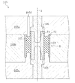
図1にその成形用金型の要部を示す。同図に示すように、成形用金型は、上下方向に組み合わされる上金型1a、下金型1b、及び中間金型1cからなる3体の部分金型を備えており、これらを組み合わせることによってその内部にキャビティ2が区画形成される。このキャビティ2内に筒形金具を配置してゴム注入孔3から未加硫のゴム材料を注入し、加硫成形することで、筒形金具とゴム材料とが一体化したラバーブッシュを製造することができる。
FIG. 1 shows the main part of the molding die. As shown in the figure, the molding die includes three partial molds including an upper mold 1a, a
尚、本実施形態では、そのラバーブッシュとして、内筒T1及び外筒T2(筒形金具)が互いにゴム部材で連結されたラバーブッシュを例に説明するが、本発明の成形用金型はこれに限らず、内外筒T1、T2の間に中間筒が備わったラバーブッシュや内筒T1や外筒T2のみのラバーブッシュにも適用可能である。 In this embodiment, a rubber bush in which the inner cylinder T1 and the outer cylinder T2 (cylindrical metal fittings) are connected to each other by a rubber member will be described as an example of the rubber bush. The present invention is not limited to this, and is also applicable to a rubber bush having an intermediate cylinder between the inner and outer cylinders T1 and T2, and a rubber bush having only the inner cylinder T1 and the outer cylinder T2.
部分金型は、いずれも金属ブロック体からなり、上金型1aの下面や中間金型1cの上下面、下金型1bの上面の各接合面がいずれも平滑に形成されていて、隙間なく密着して一体化できるように構成されている。そして、これら一体化した部分金型の内部に、ラバーブッシュ個々に対応して、略円柱形空間からなるキャビティ2がその軸線Aを上下方向に向けた状態で形成される。
Each of the partial molds is made of a metal block body, and the joint surfaces of the lower surface of the upper mold 1a, the upper and lower surfaces of the
そのキャビティ2内において、内筒T1及び外筒T2は、その筒軸を軸線Aに対して同軸に配置されるようになっていて、キャビティ2を区画している円形状の上金型1aの下面及び下金型1bの上面の各中心部には、それぞれ型締め時に内筒T1の各端面に圧接して内筒T1を移動不能に固定する上内筒固定部4a及び下内筒固定部4b(金具固定部)が設けられている。上内筒固定部4a及び下内筒固定部4bは、上記軸線Aを中心とする環形状の平滑面で構成されていて、それぞれキャビティ2内に臨んで対向している。
In the
取付け時において、内筒T1をその半径方向に位置決めするための位置決め部として、これら一対の内筒固定部4a,4bの各中心部には、キャビティ2内を軸線Aと同軸に延びてその先端部が対向する一対のピン5,5(位置決めピン)が着脱可能に設けられている。一方、外筒T2をその半径方向に位置決めするための位置決め部として、中間金型1cには位置決め孔10が設けられている。
As a positioning part for positioning the inner cylinder T1 in the radial direction at the time of attachment, the center of each of the pair of inner
まず、ピン5,5について詳しく説明すると、各ピン5は、いずれも同形状をしており、内筒T1の内径よりも僅かに径が小さいピン本体50と、このピン本体50の下端部に連なってピン本体50よりもひとまわり小径に形成された基端部51と、この基端部51から下方に突出して雄ねじが形成された雄ねじ部52と、僅かに窄まったピン本体50の上端部に凹み形成された六角レンチの差込穴53とを有している。
First, the
一方、キャビティ2に臨む、上内筒固定部4aの下面の中心部及び下内筒固定部4bの上面の中心部には、軸線Aと平行に延びるように、ピン5の基端部51が嵌合するピン嵌入孔54が開口し、その底部に連なってピン5の雄ねじ部52と螺合する雌ねじ部55が凹み形成されている。
On the other hand, the
各ピン5,5は、六角レンチを用いてその雄ねじ部52を雌ねじ部55にねじ止めすることにより、各内筒固定部4a,4bに固定される。取付け時には、これらピン5,5に挿入されることによって内筒T1は半径方向に位置決めされる。
The
そして、その位置決め時の内筒T1の同軸度を向上させるために、各ピン5の基端部51には、Oリング6(第1弾性部材)が着脱可能に装着されている。
In order to improve the coaxiality of the inner cylinder T1 at the time of positioning, an O-ring 6 (first elastic member) is detachably attached to the
詳しくは、各ピン5の基端部51の長手方向の寸法は、ピン嵌入孔54のそれよりも僅かに大きく設定されていて、ねじ止めされたピン5の付け根の基端部51の外周面に、全周に亘る溝状の装着部56が形成されるようになっている。Oリング6はその装着部56に適度に引き伸ばされた状態で装着されており、装着されたOリング6の外周側の部分は、ピン本体50の外周面よりも半径方向外側に突出し、内筒T1の内周面に接して弾性変形する変形しろとなっている。
Specifically, the longitudinal dimension of the
装着するOリング6は、かかる構成に合う寸法のものを汎用品の中から選択すればよい。ただし、加硫成形時における耐熱性を考慮すると、その材質はシリコーンゴムやフッ素ゴムが好ましい。
What is necessary is just to select the thing of the dimension which fits this structure for the O-
尚、装着部56の溝幅寸法(図の上下方向の寸法)は、Oリング6の厚み寸法よりも大きくしておくとよい。つまり、Oリング6が軸線A方向に上下動できる遊び寸法を設けておくことで、内筒T1を着脱する際にOリング6が内筒T1に引き摺られても、Oリング6が装着部56内で上下動するだけで済み、Oリング6がそこから抜け外れるのを防止することができる。
The groove width dimension (vertical dimension in the figure) of the mounting
各内筒固定部4a,4bの周りには、これを囲むようにキャビティ2の内側に突出する環状の突条部7が設けられていて、その半径方向外側には、型締め時に外筒T2の各端面に圧接して外筒T2を移動不能に固定する上外筒固定部8a及び下外筒固定部8b(金具固定部)が設けられている。
Around each of the inner
上外筒固定部8aは中間金型1cとの接合面と面一に構成されており、一方、下外筒固定部8bは外筒T2の内径よりも大きい外径寸法を有するとともに、ここでは外筒T2の外径よりも小さい外径寸法を有する幅の狭い環状の平滑な外筒受面として構成されている。この下外筒固定部8bの外側に連なる部分は、段状にこれよりも低く形成されていて、中間金型1cの下面に密着する中間金型1cの載置面となっている。
The upper outer
次に、位置決め孔10について詳しく説明すると、中間金型1cの上下面を貫通し、その内径が外筒T2の外径よりも僅かに大きい貫通孔として形成されていて、上金型1a及び下金型1bと組み合わせたときに、その軸心が上記軸線Aと同軸になるように構成されている。取付け時には、外筒T2がこの位置決め孔10に挿入されることによって、位置決め孔10を区画している中間金型1cの内周面が外筒T2の外周面に近接し、外筒T2は半径方向に位置決めされることとなる。
Next, the
その位置決め時の外筒T2の同軸度を向上させるために、本実施形態では、位置決め孔10の下端部にオイルシール部材11(第2弾性部材)が固定されている。
In this embodiment, the oil seal member 11 (second elastic member) is fixed to the lower end portion of the
オイルシール部材11は、例えば、回転軸の軸受部を密封して潤滑油などの漏れを防ぐために用いられている汎用部品であり、図1の拡大図に示すように、リング状の金属環60と、これと一体に設けられたリング状のゴム弾性体61とを含んでいる。
The
具体的には、本実施形態の金属環60は、筒状の周壁部60aと、これの下端から半径方向内側に突出する鍔部60bとを有する断面L字形状をしており、その金属環60の鍔部60bの端部に、略く字形状のゴム弾性体61が内側に張り出すように一体化されている。オイルシール部材11の構造等は、これに限らず、必要に応じて汎用品の中から選択すればよい。ただし、加硫成形時における耐熱性を考慮すると、ゴム弾性体61の材質はシリコーンゴムやフッ素ゴムが好ましい。
Specifically, the
一方、中間金型1cの位置決め孔10の下端側には、その周囲を環状に切り欠かいた切欠部70が形成されており、その切欠部70を補うように、中間金型1cの一部分としての環状の取付部材72がボルトB,Bで着脱可能に締結固定されている。
On the other hand, on the lower end side of the
その取付部材72の内周側の上端部は、下金型1bの下外筒固定部8bに近接するとともに、位置決め孔10の下端部に臨んでおり、そこに先のオイルシール部材11の金属環60が、そのゴム弾性体61を内側に向けた状態で固定されている。
The upper end portion on the inner peripheral side of the mounting
固定されたオイルシール部材11のゴム弾性体61の内周側の部分は、位置決め孔10を区画している中間金型1cの内周面よりも半径方向内側に突出し、外筒T2の外周面に接して弾性変形する変形しろとなっている。また、オイルシール部材11の下側には、位置決め孔10に挿入された外筒T2の下端面を受け止めて支持する外筒支持部73が設けられている。
A portion on the inner peripheral side of the rubber
次に、図2を参照しながら、上記構成の成形用金型におけるラバーブッシュの成形過程について説明する。 Next, a rubber bush molding process in the molding die having the above configuration will be described with reference to FIG.
まず最初は、内筒T1が下金型1bのピン5に挿入される。このとき、ピン本体50の外径は公差を考慮して内筒T1の内径よりも小さく形成されているため、挿入し易いが、内筒T1の内周面とピン本体50の外周面との間には、内筒T1ががたついて同軸度を不安定にする僅かな隙間が存在する。
First, the inner cylinder T1 is inserted into the
しかし、内筒T1の下端面が下内筒固定部4bに接するまで、つまり、Oリング6が内筒T1の内周面に接するまで内筒T1を押し込むと、Oリング6が弾性変形して内筒T1のがたつきがなくなり、軸線Aと同軸になるように押し付けられる。すなわち、内筒T1の内径寸法に多少のばらつきがあっても、従来と同様の作業で内筒T1の同軸度精度を安定して向上させることができる。
However, when the inner cylinder T1 is pushed in until the lower end surface of the inner cylinder T1 is in contact with the lower inner
一方、外筒T2は中間金型1cの位置決め孔10に挿入される。このとき、位置決め孔10の内径は公差を考慮して外筒T2の外径よりも大きく形成されているため、挿入し易いが、外筒T2の外周面と位置決め孔10の内周面との間には外筒T2ががたついて同軸度を不安定にする僅かな隙間が存在する。
On the other hand, the outer cylinder T2 is inserted into the
しかし、外筒T2の下端面が外筒支持部73に接するまで、つまり、オイルシール部材11のゴム弾性体61が外筒T2の外周面に接するまで外筒T2を押し込むと、ゴム弾性体61が弾性変形して外筒T2はがたつくことなく軸線Aと同軸になるように押し付けられる。すなわち、外筒T2の外径寸法に多少のばらつきがあっても、従来と同様の作業で外筒T2の同軸度精度を安定して向上させることができる。
However, when the outer cylinder T2 is pushed in until the lower end surface of the outer cylinder T2 is in contact with the outer
そうして、内筒T1を取付けた下金型1bに、外筒T2を取付けた中間金型1cを載置した後、さらにその中間金型1cの上面の所定位置に、上金型1aを載置することにより、各部分金型1a,1b,1cを組み合わせて一体化する。
Then, after placing the
上金型1aを載置する際にも、内筒T1には上金型1aのピン5が挿入され、先と同様にピン本体50と内筒T1との間に僅かな隙間が存在するが、内筒T1の上端面が上内筒固定部4aに接するまで押し込まれると、Oリング6が弾性変形して内筒T1のがたつきがなくなり、軸線Aと同軸になるように押し付けられて更に同軸度精度が向上する。
Even when the upper mold 1a is placed, the
次に、一体化した各部分金型1a,1b,1cを型締めすることによって、内筒T1はその両端面が上下の内筒固定部4a,4bに圧接し、外筒T2はその両端面が上下の外筒固定部8a,8bに圧接して、それぞれ移動不能に固定される。
Next, by clamping each of the integrated
続いて、キャビティ2内には未加硫のゴム材料がゴム注入孔3から注入されるが、それによって内外筒T1,T2が位置ずれを生じるおそれはなく、高精度な位置決め状態が保持される。その後、成形用金型を170℃程度に保持することで架橋が進行し、内外筒T1,T2とゴム材料とが一体化して成形過程が終了する。
Subsequently, an unvulcanized rubber material is injected into the
ところで、成形用金型は、量産するとキャビティ2内に汚れが生じるため、定期的にその汚れを取り除く洗浄処理が行われる。その洗浄処理では、キャビティ2のゴム材料との接触面に焼き付けられた離型剤も除去されてしまうことから、洗浄後には離型剤を金型に焼き付ける焼付作業が行われる。
By the way, since the molding die is soiled in the
ところがこの焼付作業では、300℃程度にまで成形用金型を加熱する必要があるため、耐熱性が十分でないOリング6やゴム弾性体61は変形するおそれがある。
However, in this baking operation, since it is necessary to heat the molding die to about 300 ° C., the O-
そこで、焼付作業の前に、Oリング6が装着された各ピン5,5を上金型1a及び下金型1bから取り外すとともに、オイルシール部材11が固定された取付部材72を中間金型1cから取り外すことで、Oリング6等の耐熱性を気にせず焼付作業を行うこうとができる。
Therefore, before the baking operation, the
また、Oリング6やオイルシール部材11の交換が簡単にできてメンテナンスが楽になる利点もある。
In addition, there is an advantage that the O-
以上、説明したように、本発明の成形用金型によれば、従来とほとんど変わらない作業でありながら、品質の安定したラバーブッシュを安価に量産することができる。 As described above, according to the molding die of the present invention, a rubber bush having a stable quality can be mass-produced at a low cost while performing almost the same work as before.
なお、本発明の成形用金型は、前記の実施の形態に限定されず、それ以外の種々の構成をも包含する。 The molding die of the present invention is not limited to the above-described embodiment, but includes various other configurations.
すなわち、上記実施形態では、成形用金型を3体の部分金型で構成しているが、それに限らず、例えば、中間金型1cを下金型1bまたは上金型1aと一体にして2体の部分金型で構成することもできる。
That is, in the above-described embodiment, the molding die is constituted by three partial dies. However, the present invention is not limited to this. For example, the
位置決めピン5は両方の内筒固定部4a,4bに設けられているが、いずれか一方だけであってもよい。
The
第1弾性部材は、ピン5の付け根以外の部位に設けてあってもよい。第2弾性部材も、位置決め孔10の下端部位だけでなく、中間部位や上端部位に設けてもよいし、両端に設けてもよい。
The first elastic member may be provided at a portion other than the root of the
第2弾性部材としては、オイルシール部材11を用いる構成以外にも、例えば、ゴム弾性体61を取付部材72と一体に成形する構成や、板リング形状のゴム片を中間金型1cと取付部材72とで挟時して、その内周部分を位置決め孔10に突出させる構成などが考えられる。
As the second elastic member, in addition to the configuration using the
また、取付部材72は必ずしも環状でなくてもよく、第2弾性部材を所定位置に取り外し可能に固定できるものであればよい。
Moreover, the
筒形金具は必ずしも金属製に限るものではなく、金属と樹脂とを組み合わせたものや樹脂でできた硬質な筒形部材であってもよい。 The cylindrical fitting is not necessarily limited to metal, and may be a combination of metal and resin or a rigid cylindrical member made of resin.
1a 上金型(部分金型)
1b 下金型(部分金型)
1c 中間金型(部分金型)
2 キャビティ
4a 上内筒固定部(金具固定部)
4b 下内筒固定部(金具固定部)
5 ピン(位置決め部)
6 Oリング(第1弾性部材)
8a 上外筒固定部(金具固定部)
8b 下外筒固定部(金具固定部)
10 位置決め孔(位置決め部)
11 オイルシール部材(第2弾性部材)
60 金属環
61 ゴム弾性体
72 取付部材
T1 内筒
T2 外筒
1a Upper mold (partial mold)
1b Lower mold (partial mold)
1c Intermediate mold (partial mold)
2
4b Lower inner cylinder fixing part (fitting fixing part)
5 pin (positioning part)
6 O-ring (first elastic member)
8a Upper outer cylinder fixing part (metal fixing part)
8b Lower outer cylinder fixing part (fitting fixing part)
10 Positioning hole (positioning part)
11 Oil seal member (second elastic member)
60
Claims (6)
型締め時に上記内筒及び外筒の筒軸方向の両端部に圧接して、これら内筒及び外筒を移動不能に固定する一対の金具固定部と、
取付け時に上記内筒及び外筒の周面に近接して、これら内筒及び外筒を半径方向に位置決めするための位置決め部と、を備え、
上記内筒の位置決め部として、少なくともいずれか一方の金具固定部からキャビティ内に延びて、上記内筒に挿入される位置決めピンを有し、
上記位置決めピンの外周面に、上記内筒の内周面に接して弾性変形する第1弾性部材が設けられ、
上記外筒の位置決め部として、当該外筒が挿入される位置決め孔を有し、
上記位置決め孔を区画している部分金型の内周面に、上記外筒の外周面に接して弾性変形する第2弾性部材が設けられていることを特徴とする成形用金型。 A plurality of partial molds each having a cavity formed therein by being combined are provided, and an inner cylinder and an outer cylinder of a rubber bush are disposed in the cavity to inject a rubber material, and the inner cylinder , the outer cylinder, and rubber A molding die for integrally vulcanization molding of materials,
A pair of metal fitting fixing parts that press-contact the both ends of the inner cylinder and the outer cylinder in the cylinder axial direction at the time of mold clamping and immobilize the inner cylinder and the outer cylinder ; and
A positioning portion for positioning the inner cylinder and the outer cylinder in the radial direction in proximity to the peripheral surfaces of the inner cylinder and the outer cylinder at the time of attachment;
As a positioning part of the inner cylinder, it has a positioning pin that extends from at least one of the metal fitting fixing parts into the cavity and is inserted into the inner cylinder,
A first elastic member that elastically deforms in contact with the inner peripheral surface of the inner cylinder is provided on the outer peripheral surface of the positioning pin,
As a positioning part of the outer cylinder, it has a positioning hole into which the outer cylinder is inserted,
A molding die, wherein a second elastic member that elastically deforms in contact with the outer peripheral surface of the outer cylinder is provided on an inner peripheral surface of the partial mold that defines the positioning hole .
上記第1弾性部材にOリングが用いられていることを特徴とする成形用金型。 In the molding die according to claim 1,
An O-ring is used for the first elastic member.
上記位置決めピンが、金具固定部に着脱可能に設けられていることを特徴とする成形用金型。 In the molding die according to claim 1 or 2,
A molding die, wherein the positioning pin is detachably attached to the metal fixture.
上記位置決めピンが、両方の金具固定部から対向して同軸状にのびる一対のピンで構成されており、
上記第1弾性部材が、各ピンの基端部に着脱可能に装着されていることを特徴とする成形用金型。 In the molding die according to any one of claims 1 to 3,
The positioning pin is composed of a pair of pins extending coaxially facing both metal fitting fixing parts,
A molding die, wherein the first elastic member is detachably attached to a base end portion of each pin.
上記第2弾性部材に、リング状の金属環と、これと一体に設けられたリング状の弾性体とを含むオイルシール部材が用いられており、
上記金属環が、部分金型に固定されていることを特徴とする成形用金型。 In the molding die according to any one of claims 1 to 4,
An oil seal member including a ring-shaped metal ring and a ring-shaped elastic body provided integrally with the second elastic member is used,
A mold for molding, wherein the metal ring is fixed to a partial mold.
上記位置決め孔の形成された部分金型は、その位置決め孔の端部に臨む一部分が着脱可能に構成されており、
上記着脱可能な部分に金属環が固定されていることを特徴とする成形用金型。 The molding die according to claim 5,
The partial mold in which the positioning hole is formed is configured such that a part facing the end of the positioning hole is detachable,
A metal mold having a metal ring fixed to the detachable part .
Priority Applications (1)
| Application Number | Priority Date | Filing Date | Title |
|---|---|---|---|
| JP2007313589A JP5285268B2 (en) | 2007-12-04 | 2007-12-04 | Mold for molding |
Applications Claiming Priority (1)
| Application Number | Priority Date | Filing Date | Title |
|---|---|---|---|
| JP2007313589A JP5285268B2 (en) | 2007-12-04 | 2007-12-04 | Mold for molding |
Publications (2)
| Publication Number | Publication Date |
|---|---|
| JP2009137070A JP2009137070A (en) | 2009-06-25 |
| JP5285268B2 true JP5285268B2 (en) | 2013-09-11 |
Family
ID=40868231
Family Applications (1)
| Application Number | Title | Priority Date | Filing Date |
|---|---|---|---|
| JP2007313589A Active JP5285268B2 (en) | 2007-12-04 | 2007-12-04 | Mold for molding |
Country Status (1)
| Country | Link |
|---|---|
| JP (1) | JP5285268B2 (en) |
Families Citing this family (4)
| Publication number | Priority date | Publication date | Assignee | Title |
|---|---|---|---|---|
| JP5576326B2 (en) * | 2011-03-18 | 2014-08-20 | 東洋ゴム工業株式会社 | Vibration isolator |
| JP2015100917A (en) * | 2013-11-20 | 2015-06-04 | トヨタ自動車株式会社 | Insert molded article, mold for insert molded article, and method for manufacturing insert molded article |
| KR101552169B1 (en) | 2013-12-10 | 2015-09-11 | 주식회사 상원 | Molded metal fixing device of molding an epoxy insulator |
| CN113352531B (en) * | 2021-05-14 | 2023-05-23 | 重庆科技学院 | Radial-pushing integrated water lubrication bearing hot-press forming die |
Family Cites Families (7)
| Publication number | Priority date | Publication date | Assignee | Title |
|---|---|---|---|---|
| JPS491627B1 (en) * | 1969-09-19 | 1974-01-16 | ||
| JPH02204009A (en) * | 1989-02-01 | 1990-08-14 | Mitsubishi Electric Corp | Casting mold assembly |
| JPH05237867A (en) * | 1992-02-28 | 1993-09-17 | Kinugawa Rubber Ind Co Ltd | Mold device |
| JP4295401B2 (en) * | 1998-12-01 | 2009-07-15 | 旭化成ケミカルズ株式会社 | Resin molded product and molding method thereof |
| JP2006289996A (en) * | 2000-06-29 | 2006-10-26 | Toyo Tire & Rubber Co Ltd | Mold for molded article with cylindrical core body |
| JP4010772B2 (en) * | 2001-02-20 | 2007-11-21 | 倉敷化工株式会社 | Mold for molding |
| JP4040985B2 (en) * | 2003-01-30 | 2008-01-30 | 東洋ゴム工業株式会社 | Non-slip processing method for metal end face of rubber member with metal fitting, and vulcanization mold used therefor |
-
2007
- 2007-12-04 JP JP2007313589A patent/JP5285268B2/en active Active
Also Published As
| Publication number | Publication date |
|---|---|
| JP2009137070A (en) | 2009-06-25 |
Similar Documents
| Publication | Publication Date | Title |
|---|---|---|
| JP5285268B2 (en) | Mold for molding | |
| CN103104581B (en) | Screw assembly element | |
| US20150274008A1 (en) | Fuel feeding device for vehicles | |
| JP6468816B2 (en) | Roller member manufacturing method, roller member mold, roller member, copying machine, and printer | |
| US10436364B2 (en) | Structure of resin-made pipe joint | |
| JP4165654B2 (en) | Method of manufacturing an assembly comprising a nut rotatably inserted into a rigid sleeve of a tail body | |
| KR20130080316A (en) | A hose forming metalic mould and making method of mandel | |
| JP2012016767A (en) | Dummy head for machining cylinder block | |
| TWI659164B (en) | Torque rod and manufacturing method thereof | |
| JP2016020743A (en) | Pipe joint | |
| US20180149110A1 (en) | Apparatus and method of use of apparatus for locating components of a system | |
| JP2009191920A (en) | Seal ring and seal ring manufacturing method | |
| JP5849261B2 (en) | Pipe fitting | |
| JP3182945U (en) | Ring mold for tire molding | |
| JP6637780B2 (en) | Nest for lens molding die and lens molding die provided with the same | |
| US10247175B2 (en) | Wax-motor with high cycle life | |
| JP2009103177A (en) | Oil seal | |
| KR101441891B1 (en) | The hot runner injection molding | |
| JP2019051730A (en) | Method of manufacturing roller member, roller member mold, roller shaft, and roller member | |
| JP5364028B2 (en) | Anti-vibration device manufacturing method | |
| JP7200020B2 (en) | INSERT COLLAR AND METHOD FOR MANUFACTURING RESIN MOLDED PRODUCT INCLUDING THE SAME | |
| CN103786319A (en) | Plunger, resin molding machine and method of resin molding | |
| JP6194230B2 (en) | Measuring jig for tire mold and method of using the same | |
| JP2013188863A (en) | Telescopic die | |
| JP2601990Y2 (en) | Mold |
Legal Events
| Date | Code | Title | Description |
|---|---|---|---|
| A621 | Written request for application examination |
Free format text: JAPANESE INTERMEDIATE CODE: A621 Effective date: 20101005 |
|
| A977 | Report on retrieval |
Free format text: JAPANESE INTERMEDIATE CODE: A971007 Effective date: 20120619 |
|
| A131 | Notification of reasons for refusal |
Free format text: JAPANESE INTERMEDIATE CODE: A131 Effective date: 20120703 |
|
| A521 | Request for written amendment filed |
Free format text: JAPANESE INTERMEDIATE CODE: A523 Effective date: 20120808 |
|
| RD02 | Notification of acceptance of power of attorney |
Free format text: JAPANESE INTERMEDIATE CODE: A7422 Effective date: 20120808 |
|
| TRDD | Decision of grant or rejection written | ||
| A01 | Written decision to grant a patent or to grant a registration (utility model) |
Free format text: JAPANESE INTERMEDIATE CODE: A01 Effective date: 20130521 |
|
| A61 | First payment of annual fees (during grant procedure) |
Free format text: JAPANESE INTERMEDIATE CODE: A61 Effective date: 20130531 |
|
| R150 | Certificate of patent or registration of utility model |
Ref document number: 5285268 Country of ref document: JP Free format text: JAPANESE INTERMEDIATE CODE: R150 |
|
| R250 | Receipt of annual fees |
Free format text: JAPANESE INTERMEDIATE CODE: R250 |
|
| R250 | Receipt of annual fees |
Free format text: JAPANESE INTERMEDIATE CODE: R250 |
|
| R250 | Receipt of annual fees |
Free format text: JAPANESE INTERMEDIATE CODE: R250 |
|
| R250 | Receipt of annual fees |
Free format text: JAPANESE INTERMEDIATE CODE: R250 |
|
| R250 | Receipt of annual fees |
Free format text: JAPANESE INTERMEDIATE CODE: R250 |
|
| R250 | Receipt of annual fees |
Free format text: JAPANESE INTERMEDIATE CODE: R250 |
|
| R250 | Receipt of annual fees |
Free format text: JAPANESE INTERMEDIATE CODE: R250 |
|
| R250 | Receipt of annual fees |
Free format text: JAPANESE INTERMEDIATE CODE: R250 |