JP5284413B2 - Ion generator - Google Patents
Ion generator Download PDFInfo
- Publication number
- JP5284413B2 JP5284413B2 JP2011111622A JP2011111622A JP5284413B2 JP 5284413 B2 JP5284413 B2 JP 5284413B2 JP 2011111622 A JP2011111622 A JP 2011111622A JP 2011111622 A JP2011111622 A JP 2011111622A JP 5284413 B2 JP5284413 B2 JP 5284413B2
- Authority
- JP
- Japan
- Prior art keywords
- ventilation path
- wall surface
- ion generator
- ion
- electrode
- Prior art date
- Legal status (The legal status is an assumption and is not a legal conclusion. Google has not performed a legal analysis and makes no representation as to the accuracy of the status listed.)
- Expired - Fee Related
Links
Images


Landscapes
- Disinfection, Sterilisation Or Deodorisation Of Air (AREA)
Description
本発明は、イオン発生装置に関し、特に、イオンセンサを備えるイオン発生装置に関する。 The present invention relates to an ion generation device, and more particularly to an ion generation device including an ion sensor.
イオン発生装置の構成を開示した先行文献として、特開2010−225558号公報(特許文献1)がある。特開2010−225558号公報(特許文献1)に記載されたイオン発生装置においては、イオン発生器の上方に、発生したイオンを捕集する捕集電極および捕集電極の電位を計測する計測部を含むイオンセンサが、長手方向を略水平にして、イオン発生器と隣接するように配されている。 As a prior document disclosing the configuration of the ion generator, there is JP 2010-225558 A (Patent Document 1). In the ion generator described in JP 2010-225558 A (Patent Document 1), a collection electrode that collects generated ions and a measurement unit that measures the potential of the collection electrode above the ion generator. Are arranged so that the longitudinal direction is substantially horizontal and adjacent to the ion generator.
イオンセンサをイオン発生器の近傍に配設した場合、イオン発生器から発生したイオンを高精度に検出できないことがある。 When the ion sensor is disposed in the vicinity of the ion generator, ions generated from the ion generator may not be detected with high accuracy.
本発明は上記の問題点に鑑みてなされたものであって、イオン発生器から発生したイオンを高精度に検出できる、イオン発生装置を提供することを目的とする。 The present invention has been made in view of the above problems, and an object of the present invention is to provide an ion generator that can detect ions generated from an ion generator with high accuracy.
本発明に基づくイオン発生装置は、吸込口から通風経路内に吸い込んだ空気を吹出口から吹き出すイオン発生装置である。イオン発生装置は、吸込口および吹出口となる複数の開口を有し、吸込口と吹出口とを繋ぐ通風経路が内部に設けられたケースと、通風経路内に位置して円筒状の外形を有し、外形の全ての接線方向に送風する遠心送風機とを備える。また、イオン発生装置は、通風経路内において遠心送風機より吹出口側に位置し、電極部を有してこの電極部からイオンを放出するイオン発生器と、通風経路内においてイオン発生器より吹出口側に位置し、通風経路内のイオン濃度を検出するイオンセンサとを備える。イオン発生器の電極部は、全ての接線方向と平行で通風経路の一部を構成する第1壁面から通風経路に臨むように位置している。イオンセンサは、全ての接線方向のうちの電極部を通過する電極部投影方向と交差して通風経路の一部を構成する第2壁面上に位置している。 The ion generator based on this invention is an ion generator which blows off the air inhaled in the ventilation path from the suction inlet from a blower outlet. The ion generator has a plurality of openings serving as an inlet and an outlet, a case in which a ventilation path connecting the inlet and the outlet is provided, and a cylindrical outer shape located in the ventilation path. And a centrifugal blower that blows air in all tangential directions of the outer shape. In addition, the ion generator is located on the outlet side of the centrifugal fan in the ventilation path, has an electrode part and discharges ions from the electrode part, and the outlet from the ion generator in the ventilation path. And an ion sensor for detecting the ion concentration in the ventilation path. The electrode part of the ion generator is positioned so as to face the ventilation path from the first wall surface that is parallel to all the tangential directions and forms a part of the ventilation path. The ion sensor is located on the second wall surface that forms part of the ventilation path intersecting with the electrode projection direction passing through the electrode portion of all the tangential directions.
本発明の一形態においては、電極部は針状の形状を有して第1壁面から通風経路の内方に突出するように位置している。 In an embodiment of the present invention, the electrode portion has a needle shape and is positioned so as to protrude inward of the ventilation path from the first wall surface.
好ましくは、イオンセンサは、イオンを捕集する捕集電極およびこの捕集電極の電位を計測する計測部を含み、捕集電極は、第2壁面上において電極部投影方向に電極部の先端部を投影した位置の近傍に位置している。 Preferably, the ion sensor includes a collection electrode that collects ions and a measurement unit that measures the potential of the collection electrode, and the collection electrode has a distal end portion of the electrode portion in the electrode projection direction on the second wall surface. It is located in the vicinity of the projected position.
本発明の一形態においては、通風経路は、遠心送風機と吹出口との間の位置にくびれ部を有している。くびれ部の一部を構成する第3壁面は、電極部投影方向に沿う方向に延在している。第2壁面は、第3壁面より吹出口側に位置して第3壁面と隣接している。 In one form of this invention, the ventilation path has a constriction part in the position between a centrifugal blower and a blower outlet. The 3rd wall surface which comprises a part of constriction part is extended in the direction in alignment with an electrode part projection direction. The second wall surface is located on the outlet side from the third wall surface and is adjacent to the third wall surface.
好ましくは、第2壁面と第3壁面との間の通風経路内側の角度をθとすると、90°<θ<180°である。 Preferably, if the angle inside the ventilation path between the second wall surface and the third wall surface is θ, 90 ° <θ <180 °.
本発明によれば、イオン発生器から発生したイオンを高精度に検出できる。 According to the present invention, ions generated from an ion generator can be detected with high accuracy.
以下、本発明の一実施形態に係るイオン発生装置について説明する。以下の実施形態の説明においては、図中の同一または相当部分には同一符号を付して、その説明は繰り返さない。 Hereinafter, an ion generator according to an embodiment of the present invention will be described. In the following description of the embodiments, the same or corresponding parts in the drawings are denoted by the same reference numerals, and the description thereof will not be repeated.
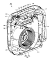
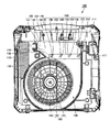
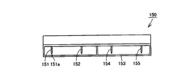
図1は、本発明の一実施形態に係るイオン発生装置の外観を示す斜視図である。図2は、本実施形態に係るイオン発生装置の内部構成を示す斜視図である。図3は、本実施形態に係るイオン発生装置の内部構造を示す一部断面図である。図4は、本実施形態に係るイオン発生装置のイオン発生器の構成を示す側面図である。図5は、本実施形態に係るイオン発生装置のイオンセンサの構成を示す平面図である。 FIG. 1 is a perspective view showing an appearance of an ion generator according to an embodiment of the present invention. FIG. 2 is a perspective view showing the internal configuration of the ion generator according to the present embodiment. FIG. 3 is a partial cross-sectional view showing the internal structure of the ion generator according to the present embodiment. FIG. 4 is a side view showing the configuration of the ion generator of the ion generator according to the present embodiment. FIG. 5 is a plan view showing the configuration of the ion sensor of the ion generator according to the present embodiment.
なお、図2,3においては、ケースの一部分およびフィルタなどのイオン発生装置の構成部品の一部を取り外した状態を図示している。 2 and 3 show a state in which a part of the case and a part of the components of the ion generator such as a filter are removed.
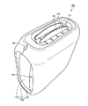
図1に示すように、本発明の一実施形態に係るイオン発生装置100は、吸込口114から通風経路内に吸い込んだ空気を吹出口115から吹き出すイオン発生装置である。イオン発生装置100は、角部に丸みが付けられた略直方体状の外形を有している。
As shown in FIG. 1, an
イオン発生装置100は、複数のケース部材が組み合わされて構成されるケース110を有している。ケース110は、それぞれ複数の切欠部を端部に有して互いに組み合わされる第1ケース部材111および第2ケース部材112を含む。
The
第1ケース部材111の複数の切欠部と第2ケース部材112の複数の切欠部とがそれぞれ組み合わされることにより、ケース110に複数の開口が形成される。複数の開口のうちの一つの開口の内側に、この開口の一部を塞ぐように第3ケース部材113が配置されている。第3ケース部材113によって塞がれていない開口の一部分が吸込口114となる。
A plurality of openings are formed in the
本実施形態においては、吸込口114と対向するように吸込口118が設けられている。図2、3に示すように、ケース110の複数の開口のうちの一つの開口の内側に、この開口の一部を塞ぐように第4ケース部材117が配置されている。第4ケース部材117によって塞がれていない開口の一部分が吸込口118となる。また、吹出口115とは反対側に吸込口119が設けられている。
In the present embodiment, a
図1〜3に示すように、吹出口115には、イオン発生装置100からの送風方向を調節する2つのルーバー116が互いに対向するように配置されている。
As shown in FIGS. 1 to 3, two
ケース110の複数の開口のうち、イオン発生装置100の角部に位置する開口内に、イオン発生装置100の電源をON/OFFするスイッチ120が配置されている。イオン発生装置100は角部に丸みが付けられているため、スイッチ120は曲面状の外表面から突出するように設けられている。
Of the plurality of openings of the
図2,3に示すように、ケース110の内部には、吸込口114,118,119と吹出口115とを繋ぐ通風経路130が設けられている。通風経路は、複数の壁面に囲まれて構成されている。吸込口114,118,119から吸い込まれた空気は、図示しないフィルタを通過した後、通風経路130を経て吹出口115から吹き出される。
As shown in FIGS. 2 and 3, a
通風経路130内には、遠心送風機である多翼ファン(シロッコファン)140が配置されている。多翼ファン140は、円筒状の外形を有し、外形の全ての接線方向に送風する。
A multiblade fan (sirocco fan) 140 that is a centrifugal blower is disposed in the
具体的には、多翼ファン140は、多数の小型の前向き羽根141をもった筒と筒の中心に位置する回転軸142とを含む。回転軸142を中心に筒が回転することにより、筒の内部の空気が、前向き羽根141同士の間から筒の外側に送風される。送風方向は、側面視において筒の円周上の全ての接線方向である。
Specifically, the
上述の通り吸込口114,118,119から通風経路130内に吸い込まれる空気がフィルタを通過した後、多翼ファン140の筒の内部に導入されるように、吸込口114,118,119と通風経路130とが接続されている。
As described above, the air sucked into the
通風経路130は、多翼ファン140の外形に沿うように湾曲した側壁を有する湾曲部と、湾曲部と隣接して吹出口115に近づくに従って経路が広くなっている拡大部とを有している。通風経路130は、湾曲部と拡大部との間にくびれ部133を有している。すなわち、通風経路130は、多翼ファン140と吹出口115との間の位置にくびれ部133を有している。
The
通風経路130内において多翼ファン140より吹出口115側にイオン発生器150が配置されている。具体的には、通風経路130のくびれ部133の近傍に、イオン発生器150が配置されている。イオン発生器150は、多翼ファン140の外形の全ての接線方向と平行で通風経路の一部を構成している第1壁面131に取り付けられている。
In the
図3,4に示すように、イオン発生器150は、針状の電極部151,152,154,155を有している。針状の電極部151,152,154,155は、通風経路130の幅方向に一列に並ぶように配置されている。くびれ部133側から順に、針状の電極部151、針状の電極部152、針状の電極部154および針状の電極部155が位置している。針状の電極部151,152,154,155は、第1壁面131から通風経路130の内方に突出するように位置している。
As shown in FIGS. 3 and 4, the
針状の電極部151,152,154,155を囲むようにカバー153が設けられている。カバー153において、針状の電極部151,152,154,155のそれぞれの先端部に対向する位置に、円形の開口156が設けられている。カバー153は、通風経路内を流動する空気と針状の電極部151,152,154,155とが接触できるように、多翼ファン140と吹出口115とを結ぶ方向において開放している。
A
針状の電極部151,152,154,155にパルス電圧が印加されることにより、針状の電極部151,152,154,155の先端部からイオンが放出される。具体的には、針状の電極部151が陰極となり、針状の電極部152が正極となる。また、針状の電極部154が陰極となり、針状の電極部155が正極となる。したがって、針状の電極部151,154からは正イオンが放出され、針状の電極部152,155からは負イオンが放出される。本実施形態においては、2組の電極部を設けたが、電極部は1組以上設けられていればよい。
By applying a pulse voltage to the needle-shaped
放出される正イオンは、水素イオン(H+)の周囲に複数の水分子が付随したクラスターイオンであり、H+(H2O)m(ただし、mは任意の自然数)と表わされる。負イオンは、酸素イオン(O2 -)の周囲に複数の水分子が付随したクラスターイオンであり、O2 -(H2O)n(ただし、nは任意の自然数)と表わされる。 The released positive ions are cluster ions in which a plurality of water molecules are attached around hydrogen ions (H + ), and are expressed as H + (H 2 O) m (where m is an arbitrary natural number). A negative ion is a cluster ion in which a plurality of water molecules are attached around an oxygen ion (O 2 − ), and is expressed as O 2 − (H 2 O) n (where n is an arbitrary natural number).
正イオンおよび負イオンを空間内に放出すると、両イオンが空気中を浮遊するカビ菌またはウィルスなどの周りを取り囲み、その表面上で互いに化学反応を起こす。その際に生成される活性種の水酸化ラジカル(・OH)の作用により、浮遊カビ菌などが除去される。 When positive ions and negative ions are released into the space, both ions surround a mold or virus floating in the air and cause a chemical reaction with each other on the surface. Suspended fungi and the like are removed by the action of the active species hydroxyl radical (.OH) generated at that time.
通風経路130内において、イオン発生器150より吹出口115側に、通風経路130内のイオン濃度を検出するイオンセンサ160が配置されている。図5に示すように、イオンセンサ160は、イオンを捕集する捕集電極162、および、捕集電極162の電位を計測する計測部が設けられている基板161を含む。
In the
基板161は、略矩形状の外形を有している。基板161に計測部となる回路が形成されている。捕集電極162は、基板161の主面上の一部に矩形状に形成されている。本実施形態においては、基板161および捕集電極162を矩形状に形成したが、これらの形状は矩形状に限られない。基板161が第1ケース部材111の内壁から膨出している挟持部に挟持されることにより、イオンセンサ160が取り付けられている。
The
基板161は、通風経路の一部を構成する第2壁面となる。第2壁面は、多翼ファン140の外形の全ての接線方向のうち、くびれ部133に最も近接している針状の電極部151を通過する電極部投影方向144と交差している。すなわち、イオンセンサ160は、イオン発生器150が取り付けられている第1壁面131とは異なる第2壁面上に位置している。
The board |
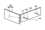
図6は、本実施形態に係るイオン発生装置において、イオン発生器とイオンセンサとの位置関係を示す斜視図である。図6に示すように、イオンセンサ160捕集電極162は、第2壁面である基板161上において電極部投影方向144に針状の電極部151の先端部151aを投影した位置の近傍に位置している。
FIG. 6 is a perspective view showing the positional relationship between the ion generator and the ion sensor in the ion generator according to this embodiment. As shown in FIG. 6, the
図7は、本実施形態に係るイオン発生装置において、くびれ部とイオンセンサとの位置関係を示す側面図である。図7に示すように、くびれ部133の一部を構成する第3壁面132は、電極部投影方向144に沿う方向に延在している。第2壁面である基板161は、第3壁面132より吹出口115側に位置して第3壁面132と隣接している。
FIG. 7 is a side view showing the positional relationship between the constricted portion and the ion sensor in the ion generator according to the present embodiment. As shown in FIG. 7, the
第2壁面と第3壁面132との間の通風経路130内側の角度をθとすると、90°<θ<180°となるように、イオンセンサ160が取り付けられている。本実施形態においては、θ=120°となるようにイオンセンサ160が取り付けられている。
The
上記の構成により、イオン発生装置100が稼動してイオン発生器150から発生したイオン、特に針状の電極部151の先端部151aから発生した陰イオンを、第3壁面132に沿って電極部投影方向144に送られる空気170に乗せて送ることができる。この空気170の流れは層流となっているため、針状の電極部151の先端部151aから発生したイオンの多くをイオンセンサ160捕集電極162に到達させることができる。その結果、イオン発生器150で発生したイオンの濃度をイオンセンサ160で高精度に計測することができる。
With the above configuration, the ions generated from the
第3壁面132に沿って送られた空気170は、第2壁面により送風方向を変えられて吹出口115に向かう空気171となる。第2壁面と第3壁面132との間の角度θを、90°<θ<180°とすることにより、イオン発生器150から発生したイオンをイオンセンサ160の捕集電極162に所定の角度で浸入させつつ、空気170の流れが第2壁面にぶつかって乱流になる度合いを抑制することができる。
The
その結果、イオンセンサ160の捕集電極162によりイオン発生器150から発生したイオンを高精度に計測しつつ、空気170に含まれる正イオンと陰イオンとが結合して消滅する量を低減して、空気171に含まれるイオン濃度を高く維持することができる。すなわち、高精度のイオン濃度計測と、高濃度のイオン吹き出しとの両方を実現することができる。
As a result, while the ions generated from the
なお、イオンセンサ160は、イオン発生装置100の稼動開始時、および稼動中の3時間毎に、通風経路130内のイオン濃度を1分間連続して計測する。イオンセンサ160による計測結果が、所定回数連続して所定のイオン濃度を下回った場合、イオン発生装置100にアラーム表示が現れるように設定されている。
The
本発明者らは、イオン発生装置100の稼動時にイオン発生器150を取り付けられている第1壁面131がイオン発生器150から発生したイオンにより帯電するため、その第1壁面131にイオンセンサ160を取り付けた場合、イオンセンサ160の捕集電極162で捕集できるイオンの量が低減して正確なイオン濃度計測ができないことを発見した。
The present inventors charge the
本実施形態に係るイオン発生装置100においては、イオンセンサ160は、イオン発生器150が取り付けられている第1壁面131とは異なる第2壁面上に位置しているため、第1壁面131の帯電の影響を抑制して高精度にイオン濃度を計測することができる。
In the
また、イオンセンサ160の捕集電極162と第2壁面である基板161と第3壁面132とを上記の位置関係に配置することにより、イオンセンサ160をイオン発生器150の近傍に配設しなくても高精度にイオン濃度を計測することができる。
In addition, by arranging the
ただし、通風経路130の構成は上記に限られず、イオンセンサ160が、イオン発生器150が取り付けられている壁面とは異なる壁面上に位置していればよい。
However, the configuration of the
本実施形態においては、電極部が針状の形状を有する針状電極であったが、電極部はこれに限られず、たとえば、沿面放電型のセラミック電極またはカーボンブラシ電極などであってもよい。この場合、電極部は、第1壁面から通風経路に臨むように位置している。 In the present embodiment, the electrode portion is a needle-like electrode having a needle-like shape, but the electrode portion is not limited thereto, and may be a creeping discharge type ceramic electrode or a carbon brush electrode, for example. In this case, the electrode part is located so as to face the ventilation path from the first wall surface.
今回開示された実施形態はすべての点で例示であって制限的なものではないと考えられるべきである。本発明の範囲は上記した説明ではなくて特許請求の範囲によって示され、特許請求の範囲と均等の意味および範囲内でのすべての変更が含まれることが意図される。 It should be thought that embodiment disclosed this time is an illustration and restrictive at no points. The scope of the present invention is defined by the terms of the claims, rather than the description above, and is intended to include any modifications within the scope and meaning equivalent to the terms of the claims.
100 イオン発生装置、110 ケース、111 第1ケース部材、112 第2ケース部材、113 第3ケース部材、114,118,119 吸込口、115 吹出口、116 ルーバー、117 第4ケース部材、120 スイッチ、130 通風経路、131 第1壁面、132 第3壁面、133 くびれ部、140 多翼ファン、141 前向き羽根、142 回転軸、144 電極部投影方向、150 イオン発生器、151,152,154,155 針状の電極部、151a 先端部、153 カバー、156 開口、160 イオンセンサ、161 基板、162 捕集電極、170,171 空気。 100 ion generator, 110 case, 111 first case member, 112 second case member, 113 third case member, 114, 118, 119 suction port, 115 air outlet, 116 louver, 117 fourth case member, 120 switch, 130 Ventilation path, 131 1st wall surface, 132 3rd wall surface, 133 constricted portion, 140 multi-blade fan, 141 forward blade, 142 rotation axis, 144 electrode projection direction, 150 ion generator, 151, 152, 154, 155 needle Electrode portion, 151a tip, 153 cover, 156 opening, 160 ion sensor, 161 substrate, 162 collection electrode, 170, 171 air.
Claims (5)
前記吸込口および前記吹出口となる複数の開口を有し、前記吸込口と前記吹出口とを繋ぐ前記通風経路が内部に設けられたケースと、
前記通風経路内に位置して円筒状の外形を有し、外形の全ての接線方向に送風する遠心送風機と、
前記通風経路内において前記遠心送風機より前記吹出口側に位置し、電極部を有して該電極部からイオンを放出するイオン発生器と、
前記通風経路内において前記イオン発生器より前記吹出口側に位置し、前記通風経路内のイオン濃度を検出するイオンセンサと
を備え、
前記イオン発生器の前記電極部は、前記全ての接線方向と平行で前記通風経路の一部を構成する第1壁面から前記通風経路に臨むように位置し、
前記イオンセンサは、前記全ての接線方向のうちの前記電極部を通過する電極部投影方向と交差して前記通風経路の一部を構成する第2壁面上に位置している、イオン発生装置。 An ion generator that blows out air sucked into a ventilation path from a suction port from a blowout port,
A plurality of openings serving as the suction port and the air outlet, and a case in which the ventilation path connecting the air inlet and the air outlet is provided inside;
A centrifugal blower that has a cylindrical outer shape located in the ventilation path and blows air in all tangential directions of the outer shape;
An ion generator located on the outlet side from the centrifugal blower in the ventilation path, having an electrode part and discharging ions from the electrode part;
An ion sensor that is located closer to the outlet from the ion generator in the ventilation path and detects an ion concentration in the ventilation path;
The electrode part of the ion generator is positioned so as to face the ventilation path from a first wall surface that is parallel to all the tangential directions and constitutes a part of the ventilation path,
The said ion sensor is an ion generator located on the 2nd wall surface which cross | intersects the electrode part projection direction which passes the said electrode part among all the said tangential directions, and comprises a part of said ventilation path.
前記捕集電極は、前記第2壁面上において前記電極部投影方向に前記電極部の先端部を投影した位置の近傍に位置している、請求項2に記載のイオン発生装置。 The ion sensor includes a collection electrode that collects ions and a measurement unit that measures the potential of the collection electrode,
The ion generating apparatus according to claim 2, wherein the collection electrode is located on the second wall surface in the vicinity of a position where a tip portion of the electrode part is projected in the electrode part projection direction.
前記くびれ部の一部を構成する第3壁面は、前記電極部投影方向に沿う方向に延在し、
前記第2壁面は、前記第3壁面より前記吹出口側に位置して前記第3壁面と隣接している、請求項1から3のいずれかに記載のイオン発生装置。 The ventilation path has a constricted portion at a position between the centrifugal blower and the outlet.
A third wall surface constituting a part of the constricted portion extends in a direction along the projection direction of the electrode portion,
The ion generator according to any one of claims 1 to 3, wherein the second wall surface is located closer to the air outlet than the third wall surface and is adjacent to the third wall surface.
Priority Applications (2)
| Application Number | Priority Date | Filing Date | Title |
|---|---|---|---|
| JP2011111622A JP5284413B2 (en) | 2011-05-18 | 2011-05-18 | Ion generator |
| CN 201220213831 CN202651619U (en) | 2011-05-18 | 2012-05-11 | ion generator |
Applications Claiming Priority (1)
| Application Number | Priority Date | Filing Date | Title |
|---|---|---|---|
| JP2011111622A JP5284413B2 (en) | 2011-05-18 | 2011-05-18 | Ion generator |
Publications (2)
| Publication Number | Publication Date |
|---|---|
| JP2012243518A JP2012243518A (en) | 2012-12-10 |
| JP5284413B2 true JP5284413B2 (en) | 2013-09-11 |
Family
ID=47420667
Family Applications (1)
| Application Number | Title | Priority Date | Filing Date |
|---|---|---|---|
| JP2011111622A Expired - Fee Related JP5284413B2 (en) | 2011-05-18 | 2011-05-18 | Ion generator |
Country Status (2)
| Country | Link |
|---|---|
| JP (1) | JP5284413B2 (en) |
| CN (1) | CN202651619U (en) |
Families Citing this family (2)
| Publication number | Priority date | Publication date | Assignee | Title |
|---|---|---|---|---|
| JP6254710B2 (en) * | 2014-09-10 | 2017-12-27 | シャープ株式会社 | Ion generator |
| WO2020032030A1 (en) * | 2018-08-10 | 2020-02-13 | シャープ株式会社 | Ion generation device |
Family Cites Families (7)
| Publication number | Priority date | Publication date | Assignee | Title |
|---|---|---|---|---|
| JP2003279089A (en) * | 2003-02-07 | 2003-10-02 | Matsushita Electric Ind Co Ltd | Negative ion generator |
| JP2005076906A (en) * | 2003-08-28 | 2005-03-24 | Sharp Corp | Air conditioner |
| JP5292820B2 (en) * | 2008-01-15 | 2013-09-18 | オムロン株式会社 | Static eliminator |
| JP4551953B2 (en) * | 2008-08-28 | 2010-09-29 | シャープ株式会社 | Ion diffusion device |
| JP5036665B2 (en) * | 2008-09-04 | 2012-09-26 | シャープ株式会社 | Ion generator and air cleaner and air conditioner equipped with the same |
| JP5382574B2 (en) * | 2009-02-23 | 2014-01-08 | Smc株式会社 | Ion balance adjustment type ionizer |
| JP4718639B2 (en) * | 2010-01-07 | 2011-07-06 | シャープ株式会社 | Ion generation cartridge |
-
2011
- 2011-05-18 JP JP2011111622A patent/JP5284413B2/en not_active Expired - Fee Related
-
2012
- 2012-05-11 CN CN 201220213831 patent/CN202651619U/en not_active Expired - Fee Related
Also Published As
| Publication number | Publication date |
|---|---|
| JP2012243518A (en) | 2012-12-10 |
| CN202651619U (en) | 2013-01-02 |
Similar Documents
| Publication | Publication Date | Title |
|---|---|---|
| JP5121878B2 (en) | Air cleaner | |
| JP4728415B2 (en) | Ion generator | |
| JP2015222171A (en) | Air conditioner | |
| CN111033131B (en) | Air supply device | |
| JP5284413B2 (en) | Ion generator | |
| US8934212B2 (en) | Ion generating apparatus and air cleaner | |
| JP5757894B2 (en) | Charged particle generator | |
| JP5423927B1 (en) | Air conditioner | |
| CN105474485B (en) | Ion generating device and air conditioner | |
| CN107926104B (en) | Static Eliminator | |
| JP2013045700A (en) | Ion generator | |
| JP2016009674A (en) | Ion generator | |
| JP2016205659A (en) | Air cleaning device | |
| WO2014058027A1 (en) | Ion generating element and ion generating apparatus | |
| JP5088359B2 (en) | Discharge unit and air conditioner | |
| JP4528851B2 (en) | Ion generator | |
| CN105407929B (en) | Air conditioner and ion generating device | |
| JP6041615B2 (en) | Blower equipment | |
| CN106537050B (en) | Air modification equipment | |
| EP2420259A1 (en) | Ion generating apparatus and air cleaning apparatus | |
| JP2013104600A (en) | Ion generator | |
| JP2018200169A (en) | Air reforming equipment | |
| JP2015045462A (en) | Air cleaner | |
| JP2012014970A (en) | Ion generating device | |
| JPWO2013057828A1 (en) | Air conditioner |
Legal Events
| Date | Code | Title | Description |
|---|---|---|---|
| A977 | Report on retrieval |
Free format text: JAPANESE INTERMEDIATE CODE: A971007 Effective date: 20130415 |
|
| A01 | Written decision to grant a patent or to grant a registration (utility model) |
Free format text: JAPANESE INTERMEDIATE CODE: A01 Effective date: 20130507 |
|
| A61 | First payment of annual fees (during grant procedure) |
Free format text: JAPANESE INTERMEDIATE CODE: A61 Effective date: 20130529 |
|
| LAPS | Cancellation because of no payment of annual fees |