JP5284411B2 - Game machine - Google Patents
Game machine Download PDFInfo
- Publication number
- JP5284411B2 JP5284411B2 JP2011099346A JP2011099346A JP5284411B2 JP 5284411 B2 JP5284411 B2 JP 5284411B2 JP 2011099346 A JP2011099346 A JP 2011099346A JP 2011099346 A JP2011099346 A JP 2011099346A JP 5284411 B2 JP5284411 B2 JP 5284411B2
- Authority
- JP
- Japan
- Prior art keywords
- payout
- motor
- flag
- game
- ball
- Prior art date
- Legal status (The legal status is an assumption and is not a legal conclusion. Google has not performed a legal analysis and makes no representation as to the accuracy of the status listed.)
- Expired - Fee Related
Links
Images


Landscapes
- Pinball Game Machines (AREA)
Description
本発明は、パチンコ機、アレンジボール機、雀球遊技機、回胴遊技機、その他遊技球や遊技メダルなどの遊技媒体を使用する遊技機に関し、特に、円滑な制御動作が実行される上に、制御プログラムの変更も容易な遊技機に関するものである。 The present invention relates to a pachinko machine, an arrangement ball machine, a sparrow ball game machine, a revolving game machine, and other game machines using game media such as game balls and game medals, and in particular, smooth control operations are executed. The present invention also relates to a gaming machine in which a control program can be easily changed.
例えば、弾球遊技機は、所定の入賞口に遊技球が入賞すると5〜15個程度の遊技球が払出される遊技機であり、払出された遊技球(賞球)が多いほど高価値の景品と交換できるようになっている。遊技球の払出には、例えば、左右の保持溝にそれぞれ複数の遊技球を保有可能な払出回転体が活用される。 For example, a bullet ball game machine is a game machine in which about 5 to 15 game balls are paid out when a game ball wins a predetermined winning opening, and the more game balls (prize balls) paid out, the higher the value. It can be exchanged for a free gift. For paying out the game balls, for example, a payout rotating body capable of holding a plurality of game balls in the left and right holding grooves is used.
このような払出回転体の回転軸には、払出モータとして例えばステッピングモータが接続され、この払出モータが所定角度(θ)ずつ間欠的に回転される結果、左右の保持溝から順番に遊技球が排出されるようになっている。なお、払出動作は、主制御基板から送信されてくる制御コマンドによって制御されており、必要なタイミングで必要な角度だけ、払出回転体が回転することによって実現されている。 For example, a stepping motor as a payout motor is connected to the rotation shaft of such a payout rotating body, and the payout motor is intermittently rotated by a predetermined angle (θ). It is supposed to be discharged. The payout operation is controlled by a control command transmitted from the main control board, and is realized by rotating the payout rotating body at a necessary angle and at a necessary angle.
このような払出装置のほか、遊技機には、液晶ディスプレイやスピーカや多数のLEDランプが接続されており、これら全体が限られた時間内に整然と動作する必要があるので、高度な制御プログラムが要求されるという実情がある。また、弾球遊技機やスロットマシンなどの遊技機は、一般に商品寿命が短く、短期間のうちに次々とバージョンアップする必要があるので、その点も考慮した設計が要求される。 In addition to such a payout device, the gaming machine is connected to a liquid crystal display, speakers, and a large number of LED lamps, and these need to operate orderly within a limited time. There is a fact that it is required. In addition, game machines such as a ball ball game machine and a slot machine generally have a short product life and need to be upgraded one after another in a short period of time.
本発明は、上記の問題点に着目してなされたものであって、限られた時間内に整然と動作するよう工夫され、また、制御内容の変更も容易な制御プログラムを具備する遊技機を提供することを課題とする。 The present invention has been made paying attention to the above-mentioned problems, and provides a gaming machine equipped with a control program that is devised to operate orderly within a limited amount of time and that can easily change control contents. The task is to do.
上記課題を解決するために、本発明は、電源遮断時にバックアップされている作業領域の情報を、維持するか消去するかを電源投入後の初期処理において決定し、その後、維持又は消去された作業領域に基づいて、遊技媒体の払出動作を含んだ定常処理が開始される遊技機であって、固定記憶領域から作業領域に転送されて使用される1バイト長の動作情報と、この動作情報の転送先を作業領域の相対アドレス値として特定する1バイト長のアドレス情報とで構成される2バイト長の情報が、識別データで特定される個数だけ記憶されたデータセットテーブルが複数個設けられ、前記識別データは、転送すべき動作情報の個数か、或いは、転送すべき動作情報がそれ以上存在しないことを示す1バイト長のデータであり、前記払出動作のために、遊技媒体の一単位の払出量に対応する数値を記憶するステップカウンタと、遊技媒体を払出す払出モータの最小回転角度の回転に要する時間に対応する数値を記憶するモータ駆動タイマとが設けられ、前記ステップカウンタ、及び/又は、前記モータ駆動タイマの初期値は、一群の動作情報の一部として所定のデータセットテーブルに格納されており、前記所定のデータセットテーブルの一群の動作情報が、前記定常処理の必要時に作業領域に転送されることで、前記ステップカウンタ、及び/又は、前記モータ駆動タイマが、初期設定される。 In order to solve the above-described problems, the present invention determines whether to maintain or erase the work area information that is backed up when the power is turned off in the initial processing after power-on, and then the work that has been maintained or erased. Based on the area, a gaming machine in which a steady process including a game medium payout operation is started, the 1-byte length of operation information transferred from the fixed storage area to the work area and used, and the operation information There are provided a plurality of data set tables in which the number of 2-byte length information configured with the address information of 1-byte length specifying the transfer destination as a relative address value of the work area is stored as many as specified by the identification data the identification data is either the number of operation information to be transferred, or is data of 1 byte length indicating that the operation information to be transferred there are no more, for the dispensing operation A step counter for storing a number corresponding to the payout amount of one unit of game media, and a motor drive timer which stores a number corresponding to the time required game media to the rotation of the minimum angle of rotation of the paying out payout motor provided the step counter, and / or an initial value of the motor driving the timer is stored in a predetermined data set table as part of a group of motion information, a group of motion information of said given data set table, The step counter and / or the motor drive timer are initialized by being transferred to the work area when the steady process is required.
固定記憶領域は、典型的にはROMであり、一方、作業領域はRAMに確保されるのが一般的である。また、動作情報には、動作状態を示すフラグ値や計数情報が含まれているのが好ましい。ここで、計数情報とは、例えば、カウンタ値や、タイマ値を意味する。前記識別データは、転送すべき動作情報の個数を示すか、或いは、転送すべき動作情報がそれ以上存在しないことを示しているのが一般的である。前者の場合には、転送プログラムが図27のように実現され、後者の場合には、転送プログラムが図28のように実現される。 The fixed storage area is typically a ROM, while the work area is generally reserved in RAM. Moreover, it is preferable that the operation information includes a flag value indicating the operation state and count information. Here, the count information means, for example, a counter value or a timer value. Generally, the identification data indicates the number of operation information to be transferred, or indicates that there is no more operation information to be transferred. In the former case, the transfer program is realized as shown in FIG. 27, and in the latter case, the transfer program is realized as shown in FIG.
データセットテーブルは、例えば、図30のように構成されており、各データセットテ
ーブルの先頭には、転送すべきデータ個数が、識別データとして記憶されている。動作情報は、図示例では、フラグ値やタイマ値などの8ビットデータであるが、これを転送すべきワークエリアのアドレス情報が組合されて記憶されている。例えば、データセットテーブル(D DSTBL4)には、3200H,375AH,45FAHの3組のデータが格納されており、00H(払出停止フラグの値)は、ワークエリアの先頭(TOP)から+32Hのエリアに格納されることを意味する。
For example, the data set table is configured as shown in FIG. 30, and the number of data to be transferred is stored as identification data at the head of each data set table. In the illustrated example, the operation information is 8-bit data such as a flag value and a timer value, but the address information of the work area to which the operation information is to be transferred is stored in combination. For example, three sets of data 3200H, 375AH, and 45FAH are stored in the data set table (D DSTBL4), and 00H (value of the payout stop flag) is in the area + 32H from the top (TOP) of the work area. Means stored.
以下、同様であり、37H(払出リトライフラグの値)はTOP+5AH番地に、また、45H(モータ停止タイマの値)はTOP+FAH番地に格納されることを意味している。ワークエリアは、例えば、図29のように構成されており、この例ではTOP番地は7F00H番地とされている。このように、ワークエリアの先頭番地の下位8bitを00Hとしておけば、図27に示すように、転送プログラムを簡素化することが可能となる。 The same applies hereinafter, and 37H (value of the payout retry flag) is stored in the TOP + 5AH address, and 45H (value of the motor stop timer) is stored in the TOP + FAH address. The work area is configured as shown in FIG. 29, for example. In this example, the TOP address is 7F00H. Thus, if the lower 8 bits of the head address of the work area are set to 00H, the transfer program can be simplified as shown in FIG.
図30のような構成のデータセットテーブルの場合には、転送プロブラム(転送処理)は、図27のように実現される。なお、図27はZ80CPUによって実行されるプログラムであるが、先ず、ワークエリアの先頭アドレスの上記8bitがDレジスタにロードされる(ST100)。なお、先に説明したように、この例では、ワークエリアの先頭アドレスは16ビット長であるが、下位8ビットは00Hとされている。 In the case of the data set table configured as shown in FIG. 30, the transfer program (transfer process) is realized as shown in FIG. FIG. 27 shows a program executed by the Z80 CPU. First, the 8 bits of the start address of the work area are loaded into the D register (ST100). As described above, in this example, the start address of the work area is 16 bits long, but the lower 8 bits are 00H.
次に、HLレジスタの示すアドレスの内容をBレジスタにロードし(ST101)、HLレジスタをインクリメントする(ST102)。このデータセット処理(サブルーチン)がCALLされるときには、HLレジスタには、何れかのデータセットテーブル(図30参照)の先頭アドレス(D DSTBL**)が格納されているので、ステップST101の処理によって、Bレジスタには、転送すべきデータの個数が格納されることになる。 Next, the contents of the address indicated by the HL register are loaded into the B register (ST101), and the HL register is incremented (ST102). When this data set process (subroutine) is CALLed, the start address (D DSTBL **) of any data set table (see FIG. 30) is stored in the HL register. , B registers the number of data to be transferred.
次に、HLレジスタの示すアドレスの内容をEレジスタにロードし(ST102)、再度、HLレジスタをインクリメントした後(ST103)、HLレジスタの示すアドレスの内容(動作情報)をACCにロードする(ST106)。そして、その値をDEレジスタの示すアドレスに転送する(ST106)。この段階では、Dレジスタには、ワークエリアの先頭アドレスの上位8ビットが格納され、EレジスタにはTOP番地からの相対アドレス値が格納されているので、ROMエリア(データセットテーブル)から読み出されたフラグ値やカウンタ値が、ワークエリアの該当番地に転送されることになる。 Next, the contents of the address indicated by the HL register are loaded into the E register (ST102), the HL register is incremented again (ST103), and the contents (operation information) of the address indicated by the HL register are loaded into the ACC (ST106). ). Then, the value is transferred to the address indicated by the DE register (ST106). At this stage, since the upper 8 bits of the start address of the work area are stored in the D register and the relative address value from the TOP address is stored in the E register, it is read from the ROM area (data set table). The flag value and counter value thus set are transferred to the corresponding address in the work area.
そこで次に、HLレジスタをインクリメントした後(ST107)、Bレジスタをデクリメントし(ST108)、BレジスタがゼロになるまでステップST102〜ST109の処理を繰り返す。以上の処理によって、各データセットテーブルに記憶されている動作情報が必要なタイミングでワークエリアに転送されることになる。なお、詳細には後述するが、データセットテーブルD DSTBL4に格納されている動作情報は、図8(b)のステップST93の処理で転送され、データセットテーブルD DSTBL21に格納されている動作情報は、図10のステップST48の処理で転送され、データセットテーブルD DSTBL26に格納されている動作情報は、図13(a)のステップS5〜S7の処理で転送される。 Therefore, next, after incrementing the HL register (ST107), the B register is decremented (ST108), and the processes of steps ST102 to ST109 are repeated until the B register becomes zero. With the above processing, the operation information stored in each data set table is transferred to the work area at a necessary timing. As will be described in detail later, the operation information stored in the data set table D DSTBL4 is transferred in the process of step ST93 in FIG. 8B, and the operation information stored in the data set table D DSTBL21 is The operation information transferred in step ST48 of FIG. 10 and stored in the data set table D DSTBL 26 is transferred in steps S5 to S7 of FIG.
本発明は弾球遊技機に適用するのが特に好適であり、請求項4に記載のように、遊技媒体の一単位の払出量に対応する数値を記憶するステップカウンタと、遊技媒体を払出す払出モータの最小回転角度の回転に要する時間に対応する数値を記憶するモータ駆動タイマとを設け、前記ステップカウンタ、及び/又は、前記モータ駆動タイマの初期値は、前記転送処理によって転送されるのが好適である。この場合には、モータの回転動作(高速回
転/低速回転、任意の回転角度)を任意に設計変更できる。なお、遊技媒体とは、典型的には、弾球遊技機で使用する遊技球や、回胴遊技機で使用するメダルである。
The present invention is particularly preferably applied to a ball game machine, and, as described in
また、払出すべき遊技媒体の総数TOTALは、基準個数Nとの関係でTOTAL=a×N+bの関係式で与えられ(b<N)、前記1単位の払出量は、N個又はb個に設定されるのが典型的である。但し、このような構成に限定されるものではなく、TOTAL=a×N1+b×N2・・・の関係式で与えられ、1単位の払出動作について、複数の基準個数N1,N2・・・Niを持つのも好適である。例えば、基準個数が5個、10個、15個のような場合であれば、総数105の遊技媒体が、15×6+10+5のように払い出される。なお、上記の係数a,b,c,・・・はゼロを含む。 Further, the total number TOTAL of game media to be paid out is given by the relational expression of TOTAL = a × N + b in relation to the reference number N (b <N), and the payout amount of one unit is N or b. It is typically set. However, it is not limited to such a configuration, and is given by a relational expression of TOTAL = a × N1 + b × N2..., And a plurality of reference numbers N1, N2. It is also suitable to have. For example, if the reference number is 5, 10, or 15, a total of 105 game media are paid out as 15 × 6 + 10 + 5. In addition, said coefficient a, b, c, ... contains zero.
また、1単位分のモータの回転動作によって間断なく全ての遊技媒体を一気に払出しても良く、この場合には、1単位=払出すべき遊技媒体の個数TOTAL、ということになる。逆に、払出しの1単位を遊技媒体1個としても良い。 Further, all game media may be paid out at once by the rotation operation of the motor for one unit. In this case, 1 unit = the number of game media TOTAL to be paid out. Conversely, one unit of payout may be one game medium.
また、請求項5に記載のように、遊技媒体の払出動作を開始していない初期状態と、1単位の遊技媒体の払出動作中である動作中状態と、1単位分の遊技媒体の払出を終えた終了状態とを設け、前記3つの状態を賞球フラグの値によって管理して循環動作させる遊技機であって、前記賞球フラグの値は、必要時に前記転送処理によって変更されているのも好適であり、この場合には、複雑な動作を円滑に実現できる。
In addition, as described in
更にまた、請求項6に記載のように、遊技媒体を払出す払出モータの非駆動状態(00H)と、払出モータが駆動状態である動作状態(5AH)と、払出モータの駆動状態を一時停止させる停止状態(A5H)とを設け、前記3つの状態を払出モータフラグの値によって管理して循環動作させる遊技機であって、前記払出モータフラグの値は、必要時に前記転送処理によって変更されているのも好適であり、この場合にも複雑な動作を円滑に実現できる。
Furthermore, as described in
以上説明したように、本発明によれば、限られた時間内に整然と動作するよう工夫され、また、制御内容の変更も容易な制御プログラムを具備する遊技機を実現できる。 As described above, according to the present invention, it is possible to realize a gaming machine equipped with a control program that is devised to operate in an orderly manner within a limited time and that can easily change control contents.
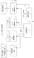
以下、本発明を実施例に基づいて本発明の実施の形態を詳細に説明する。図1は、実施例に係るパチンコ機の全体構成を図示したブロック図である。 Embodiments of the present invention will be described in detail below based on examples. FIG. 1 is a block diagram illustrating an overall configuration of a pachinko machine according to an embodiment.
図示のパチンコ機は、遊技動作を中心的に制御する主制御基板1と、表示装置8の動作を制御する図柄制御基板2と、音声的な遊技演出を実現する音声制御基板3と、ランプ類を点滅動作させるランプ制御基板4と、遊技球を払出す払出制御基板5と、払出制御基板5に制御されて遊技球を発射する発射制御基板6と、AC24Vを受けて装置各部に直流電圧を供給する電源基板7とを中心に構成されている。
The illustrated pachinko machine includes a
図示の通り、電源基板7から主制御基板1及び払出制御基板5には、電源遮断後もRAMエリアの記憶内容を維持するためのバックアップ電源が供給されている。また、主制御基板1と払出制御基板5には、係員のスイッチ操作に対応して各制御基板のRAMをゼロクリアするRAMクリア信号RAMCLRが供給されるようになっている。
As shown in the figure, backup power is supplied from the
主制御基板1、図柄制御基板2、音声制御基板3、ランプ制御基板4、及び払出制御基板5は、それぞれワンチップマイコンを備えるコンピュータ回路で構成されており、サブ制御基板2〜5は、主制御基板1からの制御コマンドに基づいて個別的な制御動作を実現
している。この実施例の場合、制御コマンドは、コマンドの種別を示すMODEデータと、具体的内容を特定するEVENTデータとが、それぞれ8ビット長で構成されている。
The
主制御基板1から払出制御基板5に伝送される制御コマンドは、払出すべき遊技球の数を指示する賞球数指定コマンド(MODEデータ=8AH)と、払出動作の停止や再開を指示する動作指定コマンド(MODEデータ=9AH)とに大別され、賞球数指定コマンド(=8A××H)は、EVENTデータ(=××H)によって賞球数を指定している。一方、動作指定コマンドには、払出停止コマンド(=9A11H)と払出再開コマンド(=9A12H)とが用意されている。
The control command transmitted from the
本実施例では、動作開始時に、主制御基板1から払出制御基板5に対して、必ず、払出停止コマンドか払出再開コマンドかを伝送するようにしている。払出停止コマンドが伝送されるのは、主制御基板での動作開始時にエラー状態が検出された場合であり、具体的には、下皿が満杯状態である場合と、遊技球の補給が途絶えている場合である。本実施例では、主制御基板1(及び払出制御基板5)での動作開始時に、払出停止コマンドか払出再開コマンドかを払出制御基板5に伝送し、これに呼応して払出制御基板5では、遊技球用の払出回転体を正確に位置合わしているが、この点については後述する。
In this embodiment, at the start of operation, the
払出停止コマンドは、動作開始時に限らず、その後の遊技動作中においても下皿が満杯状態であるか、遊技球の補給が途絶えている場合には、主制御基板1から払出制御基板5の伝送される。そして、払出停止コマンドを受信した払出制御基板5は、その時が払出動作中であっても直ちに遊技球の払出動作を停止して、その後、払出再開コマンドを受けるまでその状態で待機するようになっている。
The payout stop command is transmitted from the
後述するように、本実施例の場合、払出回転体RO(図3)に至る遊技球通路は、左右2つに区分されている。したがって、この実施例では、主制御基板1において、遊技球の補給状態を左右別々に把握して、何れか一方が補給切れ状態であれば、払出停止コマンドを払出制御基板5に対して出力するようにしている。但し、この構成に特に限定されるものではなく、左右の通路が共に補給切れの場合だけ、払出停止コマンドを出力するのでも良い。また、遊技球の補給通路の源流側で遊技球の補給状態を総体的に把握し、補給が全く途絶えた場合だけ払出停止コマンドを出力したのでも良い。
As will be described later, in the case of the present embodiment, the game ball passage leading to the payout rotating body RO (FIG. 3) is divided into two on the left and right. Therefore, in this embodiment, the
図2(a)は、払出制御基板5の周辺回路を図示したものである。図示の通り、払出制御基板5は、電源基板7から(バックアップ電源を含む)電源電圧だけでなく、払出制御基板5(ワンチップマイコン)のRAMをクリアするための指令信号RAMCLRと、電源電圧の降下に伴うNMI(non maskable interrupt)信号と、電源リセット信号SYSRSTなどを受けている。また、払出制御基板5は、プリペイドカードユニット22とも接続され、球貸し動作に係わる各種の制御信号(BRDY,BRQ,EXS,PRDY)を送受している。そして、球貸し情報信号を外部に出力するようになっている。なお、払出制御基板5は、プリペイドカードユニット22から直流電圧18vを受けており、この電圧値を正常に受信できることを条件に発射制御基板6の動作を許可している。
FIG. 2A illustrates a peripheral circuit of the
払出制御基板5は、遊技球の入賞に伴う賞球か、又はプリペイドカードで清算される貸し球として、所定数の遊技球を払出す必要がある。そこで、ステッピングモータたる払出モータMに4相の駆動パルスデータΦ1〜Φ4を出力し、払出モータMの回転に伴って払出される遊技球を、左右の賞球計数スイッチRSW1,LSW1か又は左右の球貸し計数スイッチRSW2,LSW2で検出するようにしている。なお、図2(a)に示す通り、左右の賞球計数スイッチRSW1,LSW1の信号は、主制御基板1にも伝送されるようになっている。
The
図3は、払出モータMとその周辺部材について図示したものである。図示の通り、払出モータMの回転軸に接続された払出回転体ROには、それぞれ遊技球6個を保有可能な保持溝が左右に形成されている。この払出回転体ROの回転に伴い、保持溝に保持された遊技球は、左右から交互に1個ずつ下方に放出されるが、この実施例では、通常時には、18mS毎に変化する駆動データΦ1〜Φ4が、4ステップ出力されて(払出回転体ROが30°回転され)1個の遊技球を払出している(図2(b)及び、図4参照)。 FIG. 3 illustrates the payout motor M and its peripheral members. As shown in the drawing, the payout rotating body RO connected to the rotating shaft of the payout motor M is formed with holding grooves on the left and right that can hold six game balls. Along with the rotation of the payout rotating body RO, the game balls held in the holding groove are alternately released downward from the left and right one by one. In this embodiment, however, the driving data Φ1 that changes every 18 mS is normal. .About..PHI.4 is output in four steps (the payout rotating body RO is rotated by 30.degree.) To pay out one game ball (see FIG. 2 (b) and FIG. 4).
図3に示すように、払出回転体ROの下流側通路には、賞球計数スイッチRSW1,LSW1と球貸し計数スイッチRSW2,LSW2が設けられている。また、払出動作切換え用のレバーLEが配置されており、この払出切換レバーLEで案内されることによって、遊技球は、賞球計数スイッチか球貸し計数スイッチの何れかを通過することになる。払出切換レバーLEは、図2に示す払出切換ソレノイドのON/OFF動作に応じて、姿勢を切換えるようになっており、図3は、左右の賞球計数スイッチRSW1,LSW1が遊技球の通過を検出する賞球動作状態を図示している。なお、左右の賞球計数スイッチRSW1,LSW1(及び球貸し計数スイッチRSW2,LSW2)の信号は、払出制御基板5に伝えられ、必要数の球貸し動作と賞球動作とが管理されている。
As shown in FIG. 3, prize ball counting
図6は、払出制御基板5の内部構成を図示したものである。図示の通り、払出制御基板5は、主制御基板からの制御コマンドを受ける入力バッファ10と、賞球及び球貸し計数スイッチからのスイッチ信号を受けるコンパレータ群11と、第1入力ポート13と、第2入力ポート12と、Z80CPU相当品を内蔵するワンチップマイコン14と、入出力ポートのチップセレクト信号を生成するデコーダ15と、第1出力ポート16と、第2出力ポート17と、第1出力ポート16から受けた駆動信号を払出モータMに供給するトランジスタ群(オープンコレクタ)18とを中心に構成されている。
FIG. 6 illustrates the internal configuration of the
なお、この実施例では、入力バッファ10、第1と第2の入力ポート12,13は、74541相当品のバスバッファで構成され、デコーダは、74138相当品で構成されている。また、出力ポート16,17は、74273相当品のD型フリップフロップで構成されている。
In this embodiment, the
図示の通り、第1入力ポート13のbit0,bit1には、左右の賞球計数スイッチSW1(R,L)からの信号が供給され、bit2,bit3には、左右の球貸し計数スイッチSW2(R,L)からの信号が供給されている。また、bit4には、マニュアル操作される異常解除スイッチERSからの信号が供給され、bit5には電源基板7からのRAMクリア信号RAMCLRが供給されている。なお、第1の入力ポート13のbit6〜7にはプリペイドカードユニット22からの制御信号BRDY,BRQが供給されている。
As shown in the figure, the signals from the left and right prize ball counting switches SW1 (R, L) are supplied to bit0, bit1 of the
先に説明した通り、第2入力ポート12には主制御基板1からの制御コマンドが伝えられるが、主制御基板1からは、制御コマンドの伝送に合わせてストローブ信号STBが供給される。このストローブ信号STBは、CPUコアの割込み端子(maskable interrupt)に供給されるので、これに応じて、払出制御基板5では受信割込みルーチンが起動し、制御コマンドを取得するようになっている。
As described above, the control command from the
第1出力ポート16のbit3〜bit0からは、(Φ4,Φ3,Φ2,Φ1)=0101→0110→1010→1001→0101→・・・の駆動パルスデータが時間順次に払出モータMに対して出力される(図5参照)。また、第1出力ポートのbit4にはLED駆動信号がエラー報知ランプERLに出力され、bit7からは、不図示のウォッチドッグタイマ回路のクリア信号が所定時間毎に出力されるようになっている。
From the
一方、第2出力ポート17のbit0からは、切換えレバーLEの姿勢を切換える際に、切換え信号が切換えソレノイドに対して出力される。また、第2出力ポート17のbit3からは外部出力用の球貸し情報信号が出力され、bit6,bit7からはプリペイドカードユニット22に対して、制御信号PRDY,EXSが出力される。
On the other hand, from bit0 of the
図7は、図6に示す払出制御基板5で実行されるプログラムを説明するフローチャートである。払出制御基板5の動作は、概説すると、電源投入後に開始されて無限ループ状に繰り返されるメインルーチン(図7(a))と、主制御基板1からのストローブ信号STBによって起動される割込み処理ルーチン(図7(b))と、一定時間(2mS)毎に開始されるタイマ割込みルーチン(図7(c))と、電源電圧降下時に電源基板7からNMI信号を受けて開始されるマスク不能のNMIルーチン(図7(d))とで構成されている。
FIG. 7 is a flowchart for explaining a program executed by the
図7(b)に示すように、受信割込みルーチンでは、第1入力ポート12から制御コマンドを取得して、これをRAMのコマンドバッファ領域に格納して処理を終える(ST100)。また、図7(c)に示すように、タイマ割込みルーチンでは、割込み確認フラグを5AHに書き換えて処理を終える(ST200)。この割込み確認フラグの値は、メインルーチンのステップST10においてチェックされ、この値が5AHであることを条件にメインルーチンの処理が進行するようになっている。すなわち、メインルーチンの割込み待ち処理(ST10)では、割込み確認フラグが5AHとなるのを待ち、5AHとなれば割込み確認フラグを00Hに書換えた後にステップST11の処理に移行する。したがって、ST11以下の処理は2mS毎に繰返し実行されることになる。
As shown in FIG. 7B, in the reception interrupt routine, a control command is acquired from the
図7(d)に示すように、NMIルーチンでは、レジスタの値を退避させた後(ST301)、スタックポインタSPの値をRAMの記憶エリアに保存する(ST302)。次に、第2入力ポート12から制御コマンドを入力し、もし新規の制御コマンドであれば、RAMのコマンドバッファ領域に格納する(ST303)。その後、最低限の処理が終わったことを示すべく、バックアップフラグBAKFLGに5AHを格納した後(ST304)、RAMエリアのチェックサム値(8bit長)を算出して該当エリアに記憶する(ST305)。最後にワンチップマイコンをRAMアクセス禁止状態に設定して(ST305)、無限ループ処理を実行しつつ電源電圧が遮断されるのを待つ(ST306)。
As shown in FIG. 7D, in the NMI routine, after the register value is saved (ST301), the value of the stack pointer SP is saved in the RAM storage area (ST302). Next, a control command is input from the
以上の動作を踏まえてメインルーチン(図7(a))の動作内容を説明する。電源基板7から電源電圧が供給されると共に、システムリセット信号SYSRSTが供給されると、CPUを割込み禁止状態に設定した後(ST1)、ワンチップマイコン14各部の初期設定を行う(ST2)。次に、第1入力ポート13からのデータに基づき、電源基板7からRAMクリア信号が供給されているか否かをチェックする(ST3)。この実施例では、パチンコホールの営業開始時であって、特に係員が電源基板7のRAMクリアスイッチをON操作した場合にはRAMクリア信号RAMCLRが供給されるが、停電からの復旧時を含め、通常はRAMクリア信号が供給されない。
Based on the above operation, the operation content of the main routine (FIG. 7A) will be described. When the power supply voltage is supplied from the
そして、RAMクリア信号が供給されない場合には、NMIルーチンのステップST304の処理で記憶されるバックアップフラグBAKFLGの値をチェックし(ST4)、BAKFLG=5AHであれば、次に、NMIルーチンのステップST305の処理で記憶されたチェクサム値を確認する(ST5)。このメインルーチンで算出したサム値と、NMIルーチンで記憶されたサム値とが一致する場合には、バックアップ復帰処理を実行してバックアップ処理前の処理に戻る(ST19)。 If the RAM clear signal is not supplied, the value of the backup flag BAKFLG stored in the processing of step ST304 of the NMI routine is checked (ST4). If BAKFLG = 5AH, next, step ST305 of the NMI routine is performed. The checksum value stored in the above process is confirmed (ST5). If the sum value calculated in the main routine matches the sum value stored in the NMI routine, the backup restoration process is executed and the process returns to the process before the backup process (ST19).
バックアップ復帰処理は具体的には図16に示す通りである。先ず、ステップST30
2の処理でバックアップされたスタックポインタSPの値を復帰させ(ST400)、復帰後払出停止フラグと復帰状態フラブとを5AHに設定する(ST401)。また、復帰処理が完了したことを示すべくバックアップ確認フラグを00Hにクリアし、スタックポインタSPの記憶エリアをゼロクリアする(ST401)。その後、レジスタの値を復帰させ(ST402)、NMI処理の実行前の状態に戻る。
Specifically, the backup recovery processing is as shown in FIG. First, step ST30
The value of the stack pointer SP backed up in the
ところで、ステップST401の処理によって復帰状態フラグが5AHに設定されたことにより、復帰状態フラグが00Hにクリアされるまでは、主制御基板1から伝送される制御コマンド(払出停止コマンドか払出再開コマンド)は、通常のコマンドバッファではなく、特別な復帰用のコマンドバッファ領域に格納される。なお、5AHに設定された復帰状態フラグは、払出停止コマンドか払出再開コマンドを、復帰用のコマンドバッファ領域に格納した段階でゼロクリアされる。
By the way, the control command (payout stop command or payout restart command) transmitted from the
以上、電源投入時にRAMクリアスイッチがON操作されない場合を説明したが、図7に戻ってメインルーチンの説明を続ける。営業開示時に係員がRAMクリアスイッチをON操作した場合、及び、NMIルーチンが正常に終了するまでに電源電圧が降下したような場合には、ワンチップマイコン14のRAM領域がゼロクリアされる(ST7)。なお、NMIルーチンが正常に終了するまでに電源電圧が降下したことは、BAKFLG≠5AHであるか、又はチェックサムエラーによって検出され、このような場合には正常なバックアップ復帰が不可能と考えられるのでRAM領域をゼロクリアするのである。
The case where the RAM clear switch is not turned on when the power is turned on has been described above. Returning to FIG. 7, the description of the main routine will be continued. When the staff member turns on the RAM clear switch at the time of business disclosure, and when the power supply voltage drops before the NMI routine ends normally, the RAM area of the one-
そして、その後、払出停止フラグに5AHを設定して(ST8)、CPUを割込み許可状態に戻す(ST9)。なお、ステップST8における払出停止フラグの設定は、後述する払出モータMの位置合わせ動作に密接に関係している。 Thereafter, 5AH is set in the payout stop flag (ST8), and the CPU is returned to the interrupt enabled state (ST9). The setting of the payout stop flag in step ST8 is closely related to the alignment operation of the payout motor M described later.
続いて、ステップST10〜ST18の処理が無限ループ状に繰り返されるが、ST11〜ST18の無限ループ処理は、前述した割込み待ち処理(ST10)によって一定時間毎(2mS)に実行される。無限ループ処理では、先ず、第1入力ポート13を通して、スイッチ入力信号が取得される(ST11)。これは、払出モータMの回転によって遊技球が払出されたか否かを確認するための処理である。続いて、8bit長又は16bit長のタイマの減算処理(−1)が行われる(ST12)。なお、無限ループ処理が2mS毎に実行されることにより、減算タイマの1単位時間は2mSを意味する。 Subsequently, the processes in steps ST10 to ST18 are repeated in an infinite loop, and the infinite loop processes in ST11 to ST18 are executed at regular intervals (2 mS) by the interrupt wait process (ST10) described above. In the infinite loop process, first, a switch input signal is acquired through the first input port 13 (ST11). This is a process for confirming whether or not the game ball has been paid out by the rotation of the payout motor M. Subsequently, a subtraction process (-1) of an 8-bit or 16-bit timer is performed (ST12). Note that one unit time of the subtraction timer means 2 mS by executing the infinite loop process every 2 mS.
タイマ減算処理が終われば、次に、受信割込み処理によって取得される制御コマンドの解析処理が行われる(ST13)。コマンド解析処理は、図8(a)に示すように、バックアップ復帰時のコマンド解析処理(ST85〜ST88)と、通常時のコマンド解析処理(ST89〜ST90)に区分されるが、これが2mS毎に毎回実行される。 When the timer subtraction process is completed, the control command obtained by the reception interrupt process is analyzed (ST13). As shown in FIG. 8A, the command analysis process is divided into a command analysis process (ST85 to ST88) at the time of backup restoration and a command analysis process (ST89 to ST90) at the normal time. It is executed every time.
図8(a)に示すように、コマンド解析処理では、先ず、復帰時用のコマンドバッファの値が取得される(ST85)。図16に関して先に説明したように、バックアップ復帰状態であれば、主制御基板1から伝送される最初の制御コマンド(払出停止コマンドか払出再開コマンド)は、復帰時用のコマンドバッファに格納される。なお、主制御基板1は、電源投入時には、バックアップ復帰時も含めて、遊技球に関するエラー状態が検出されない限り、最初に、払出再開コマンドを払出制御基板5に伝送するのは前述した通りである。但し、賞球数指定コマンドを送信中に電源が遮断した場合には、例外的に、賞球数指定コマンドを送信する。一方、下皿満杯状態や遊技球の補給切れを検出すれば、主制御基板1は、最初に払出停止コマンドを伝送する。
As shown in FIG. 8A, in the command analysis process, first, the value of the command buffer for return is acquired (ST85). As described above with reference to FIG. 16, in the backup return state, the first control command (payout stop command or payout resume command) transmitted from the
復帰時用のコマンドバッファから払出停止コマンドか払出再開コマンドが検出されるのは、停電状態などからの復帰時か、或は、電源投入時に係員がRAMクリアスイッチを操
作しない場合であるが、もし、払出再開コマンドが検出されたら、払出リトライフラグを5AHに設定し、モータ停止タイマを250に設定する(ST87a)。また、払出停止フラグと復帰後払出停止フラグとを00Hにクリアする(ST87a)。
The payout stop command or payout resume command is detected from the command buffer for return when recovering from a power failure or when the staff does not operate the RAM clear switch when the power is turned on. When the payout restart command is detected, the payout retry flag is set to 5AH, and the motor stop timer is set to 250 (ST87a). Further, the payout stop flag and the post-return payout stop flag are cleared to 00H (ST87a).
払出停止フラグと復帰後払出停止フラグとがクリアされたことにより、払出動作が可能となるが、払出リトライフラグ=5AHとなったことにより遊技球を1個払出すまで払出モータをゆっくり回転させるリトライ動作ステイタスモード(図11(b))に設定されたことになる。また、モータ停止タイマ=250となったことにより、このリトライ動作によるに遊技球の払出に先立って、500mS(=250×2)だけモータが停止状態に維持されることになる。ここで、モータの停止状態とは、ステッピングモータMに同じ駆動パルス(Φ1〜Φ4)が供給され続けることを意味し、ステッピングモータMが非駆動状態(トランジスタ群18が全てOFF)であることとは区別される。
The payout operation is enabled by clearing the payout stop flag and the payout stop flag after return. However, when the payout retry flag is 5 AH, the payout motor is rotated slowly until one game ball is paid out. The operation status mode (FIG. 11B) is set. In addition, since the motor stop timer is set to 250, the motor is maintained in the stopped state by 500 mS (= 250 × 2) prior to the payout of the game ball by the retry operation. Here, the stopped state of the motor means that the same drive pulses (Φ1 to Φ4) are continuously supplied to the stepping motor M, and that the stepping motor M is in a non-driven state (all
一方、ステップST86の判定の結果、復帰時用のコマンドバッファから払出停止コマンドが検出された場合には、払出停止フラグを5AHに設定し、復帰後払出停止フラグをクリアする(ST87b)。そして、ステップST87a,ST87bの何れの処理を実行した場合も、復帰時用のコマンドバッファの値はゼロクリアされる(ST88)。 On the other hand, if a payout stop command is detected from the return command buffer as a result of the determination in step ST86, the payout stop flag is set to 5AH, and the post-return payout stop flag is cleared (ST87b). Then, when any of the processes of steps ST87a and ST87b is executed, the value of the command buffer for return is cleared to zero (ST88).
図16に関して説明したように、復帰時用のコマンドバッファが使用されるのは、復帰状態フラグが5AHの場合に限られ、この復帰状態フラグは、復帰時用のコマンドバッファを1度でも使用するとクリアされるので、結局、ステップST87aかST87bの何れかの処理が実行された後は、ステップST87〜ST88の処理は常にスキップされることになる。 As described with reference to FIG. 16, the command buffer for return is used only when the return status flag is 5AH. This return status flag indicates that the command buffer for return is used even once. Since it is cleared, the process of steps ST87 to ST88 is always skipped after the process of either step ST87a or ST87b is executed.
したがって、その後は、2mS毎に新規に受信した制御コマンドの解析処理(ST89,ST90)が行われることになる。具体的には、新規に受信した制御コマンドの正当性が確認されると(ST89)、制御コマンドの下位8bitであるEVENTデータのチェックが行われる(ST90)。 Therefore, thereafter, analysis processing (ST89, ST90) of the newly received control command is performed every 2 mS. Specifically, when the validity of the newly received control command is confirmed (ST89), the EVENT data which is the lower 8 bits of the control command is checked (ST90).
図8(b)はイベントチェック処理(ST90)の内容を図示したものであり、先ず、新規に受信した制御コマンドが払出再開コマンドか否かが判定される(S91)。ここで、払出再開コマンドが検出される場合とは、RAMクリアスイッチを操作して電源を投入した場合か、電源遮断時にバックアップ動作が不完全であって、且つ、遊技球に係わる異常事態が生じていない場合である。 FIG. 8B illustrates the contents of the event check process (ST90). First, it is determined whether or not the newly received control command is a payout restart command (S91). Here, when the payout restart command is detected, the RAM clear switch is operated to turn on the power, or the backup operation is incomplete when the power is cut off, and an abnormal situation relating to the game ball occurs. If not.
そのような場合には、払出動作を停止すべきか否かを規定している払出停止フラグの値が判定され(ST92)、払出動作が可能な場合には、払出停止フラグ=00H、払出リトライフラグ=5AH、モータ停止タイマ=250に設定される(ST93)。 In such a case, the value of the payout stop flag that defines whether or not the payout operation should be stopped is determined (ST92). If the payout operation is possible, the payout stop flag = 00H, the payout retry flag. = 5AH and motor stop timer = 250 are set (ST93).
払出リトライフラグ=5AHとなったことにより、遊技球を1個払出すまで払出モータをゆっくり回転させるリトライ動作ステイタスモード(図11(b))に設定されたことになる。また、モータ停止タイマ=250となったことにより、このリトライ動作によるに遊技球の払出に先立って、500mS(=250×2)だけモータが停止状態に維持される。この点は、バックアップ復帰処理(S19)を経過して遊技機の動作が開始された場合と同様である。 Since the payout retry flag is set to 5AH, the retry operation status mode (FIG. 11 (b)) in which the payout motor rotates slowly until one game ball is paid out is set. In addition, since the motor stop timer is set to 250, the motor is maintained in the stop state by 500 mS (= 250 × 2) prior to the payout of the game ball by this retry operation. This is the same as the case where the operation of the gaming machine is started after the backup return processing (S19).
ステップST91の判定がNOの場合には、新規に受信した制御コマンドが払出停止コマンドか否か判定される(ST94)。そして、払出停止コマンドが受信されていた場合には、払出停止フラグの値が判定され(ST95)、もし00Hであれば払出動作を停止すべく、払出停止フラグ=5AHに設定する(ST96)。 If the determination in step ST91 is no, it is determined whether the newly received control command is a payout stop command (ST94). If the payout stop command has been received, the value of the payout stop flag is determined (ST95). If it is 00H, the payout stop flag is set to 5AH to stop the payout operation (ST96).
一方、ステップST94の判定の結果、新規に受信した制御コマンドが遊技球の払出個数を規定する賞球数指定コマンドであった場合には、全賞球数カウンタに、新たに指示された賞球数を加える(ST97)。このように、コマンド解析処理(ST13)によって、遊技機から払出すべき遊技球の総数が、受信した制御コマンドに基づいて順次更新されている(ST97)。 On the other hand, as a result of the determination in step ST94, if the newly received control command is a prize ball number designation command that defines the number of game balls to be paid out, the newly designated prize ball is displayed in the total prize ball number counter. A number is added (ST97). As described above, the total number of game balls to be paid out from the gaming machine is sequentially updated based on the received control command by the command analysis process (ST13) (ST97).
以下、図7に戻ってメインルーチンの説明を続けると、プリペイドカードユニット22との通信処理(ST14)と、プリペイドカードで清算される球貸し処理(ST15)とを行った後、賞球処理(ST16)とモータ処理(ST17)とデータ出力処理(ST18)とが行われ、ステップST10の処理に戻る。 Hereinafter, returning to FIG. 7, the description of the main routine will be continued. After performing the communication process with the prepaid card unit 22 (ST14) and the ball lending process (ST15) cleared by the prepaid card, the prize ball process ( ST16), motor processing (ST17), and data output processing (ST18) are performed, and the processing returns to step ST10.
モータ処理(ST17)は、払出モータMを回転させるための準備処理であり、具体的には、払出モータM用の駆動データ(Φ1〜Φ4)を生成してワークエリアMOOUTに格納している。一方、データ出力処理(ST18)は、前記した駆動データを含む各種のデータを、第1と第2の出力ポート16,17から出力する処理である。また、賞球処理(ST16)は、賞球の払出数を管理する処理であり、コマンド解析処理(ST13)によって更新された全賞球数カウンタの値に基づいて払出数を決定し、データ出力処理(ST18)によって払出モータMを回転させると共に、データ入力処理(ST11)で把握される遊技球の払出し状態を参照して払出モータの動作終了タイミングなどを決定している。
The motor process (ST17) is a preparation process for rotating the payout motor M. Specifically, drive data (Φ1 to Φ4) for the payout motor M is generated and stored in the work area MOOUT. On the other hand, the data output process (ST18) is a process for outputting various data including the drive data from the first and
賞球処理(ST16)とモータ処理(ST17)の説明に先立って、図15に基づいてデータ出力処理(ST18)から説明する。データ出力処理では、先ず、モータ処理(具体的には図11のST68)で用意されたモータ駆動データをMOOUT番地から取得する(ST70)。なお、モータ駆動データは2進数で0101,0110,1010,1001の何れかであり、それらが図5に示すように出力されることで払出モータMが回転する。なお、この実施例では、通常時、払出モータMの1ステップの回転時間が18mSに設定され、4ステップ分のデータ駆動データの出力によって払出モータMが30度回転して遊技球を1個払出すように設定されている。なお、払出モータMの1ステップの回転時間は、モータ駆動タイマで管理されており、1ステップ分の回転時間18mSが、タイマ割込み9回分に相当することから、通常動作時にはモータ駆動タイマの初期値は9に設定される。
Prior to the description of the prize ball processing (ST16) and the motor processing (ST17), the data output processing (ST18) will be described based on FIG. In the data output process, first, motor drive data prepared in the motor process (specifically, ST68 in FIG. 11) is acquired from the MOOUT address (ST70). Note that the motor drive data is
何れにしてもステップST70の処理によって、モータ駆動データがBレジスタに用意されたら、LEDフラグが5AHにセットされているか判定される(ST71)。LEDフラグとは、払出動作の異常状態が所定時間(22.4秒)継続した場合に、エラー報知ランプERL(図6参照)を点灯させるためのフラグである。したがって、LEDフラグが5AHであれば、Bレジスタのbit4を1にセットする(ST73)。
In any case, if motor drive data is prepared in the B register by the process of step ST70, it is determined whether the LED flag is set to 5AH (ST71). The LED flag is a flag for turning on the error notification lamp ER L (see FIG. 6) when the abnormal state of the payout operation continues for a predetermined time (22.4 seconds). Therefore, if the LED flag is 5AH,
次にBレジスタのbit7を1に設定し(ST73)、Bレジスタの値を、第1出力ポート16に出力する(ST74)。この結果、払出モータMには駆動データが出力され、エラー報知ランプERLが点灯又は消灯する。また、Bレジスタのbit7は、ウォッチドッグタイマに出力されるので、時間消費処理(ST75)の後、bit7をゼロに戻して、第1出力ポート16から再出力している(ST7)。この動作によってウォッチドッグタイマがゼロクリアされるが、プログラムの暴走によって、本来2mS毎に実行されるべきデータ出力処理(ST18)が実行されなくなると、ウォッチドッグタイマ回路の動作に基づいてCPUが強制的にリセットされることになる。
Next,
何れにしてもステップST76の処理に続いて、切換えソレノイドフラグ、球貸し信号
フラグ、PRDYフラグ、EXEフラグを参照して、該当ビットをセットしたデータを第2出力ポート17に出力する(ST78)。この動作の結果、場合によっては、球貸し情報信号が外部に出力され、切換えレバーLE(図3)の姿勢が変更される。なお、PRDY信号やEXE信号は、プリペイドカードユニット22に出力される制御信号である。
In any case, following the processing of step ST76, the switching solenoid flag, the ball lending signal flag, the PRDY flag, and the EXE flag are referred to, and data in which the corresponding bit is set is output to the second output port 17 (ST78). As a result of this operation, in some cases, a ball lending information signal is output to the outside, and the attitude of the switching lever LE (FIG. 3) is changed. The PRDY signal and the EXE signal are control signals output to the
以上、図7に示すメインルーチンについて概略的に説明したが、続いて、図9〜図14を参照しつつ、賞球処理(ST16)とモータ処理(ST17)とを詳細に説明する。図9に示すように、賞球処理では、最初に賞球が検出されたか否かが判定される(ST20)。賞球の払出は、データ出力処理(ST18)に起因して払出モータMが1ステップ回転した場合に生じ得るが、もし、払出があればステップST11の処理によってスイッチエッジデータとして取得されている。なお、この実施例では、スイッチエッジデータのbit0が、左賞球計数スイッチの検出状態を表し、bit1が右賞球計数スイッチの検出状態を表している(図6参照)。
While the main routine shown in FIG. 7 has been schematically described above, the winning ball process (ST16) and the motor process (ST17) will be described in detail with reference to FIGS. As shown in FIG. 9, in the prize ball process, it is first determined whether or not a prize ball is detected (ST20). The payout of the prize ball may occur when the payout motor M rotates one step due to the data output process (ST18). If there is a payout, it is acquired as switch edge data by the process of step ST11. In this embodiment,
賞球検出処理(ST20)の具体的内容は図10に示す通りであり、左右の賞球データ(スイッチエッジデータのbit0とbit1)を変数D1に取得すると共に、Bレジスタに2を設定する(ST40)。次に、変数D1を右に1ビットシフト演算することで、スイッチエッジデータのbit0の内容をキャリーフラグCYに移動させる(ST41)。
The specific contents of the winning ball detection process (ST20) are as shown in FIG. 10, and the left and right winning ball data (
CY=1であれば左賞球計数スイッチがONであることを意味するが、この段階では払出モータの回転が開始されていないのでCY=0のはずである。そこで、Bレジスタの値を−1して(ST49〜ST50)、更に変数D1を右に1ビットシフト演算する(ST41)。この段階でCY=1であれば右賞球計数スイッチがONであることを意味するが、この段階では払出モータの回転が開始されていないのでCY=0のはずである。したがって、ステップST49〜50の処理を経て賞球検出処理を終える。 If CY = 1, it means that the left prize ball counting switch is ON, but at this stage, since the rotation of the payout motor has not started, CY = 0 should have been assumed. Therefore, the value of the B register is decremented by -1 (ST49 to ST50), and the variable D1 is further shifted to the right by 1 bit (ST41). If CY = 1 at this stage, it means that the right prize ball counting switch is ON, but at this stage, since the rotation of the payout motor has not started, CY = 0 should have been assumed. Accordingly, the prize ball detection process is completed through the processes of steps ST49 to ST50.
一方、払出モータMの回転が開始された後は、ステップST42の判定でCY=1となる場合がある。そこで、その場合には、賞球フラグの内容をチェックする(ST43)。賞球フラグは、本実施例の払出動作を管理するフラグの一つであり、当初は00Hであるが、払出残数カウンタに1単位分(25個以下)の払出数を設定した段階で5AHに設定されるようになっている(図9のST27〜ST29)。そして、1単位分の払出が終わり、払出残数カウンタの値がゼロになると賞球フラグの値がA5Hに変更され(図10のST48)、その後直ちに初期状態の00Hに戻される(図9のST31)。 On the other hand, after rotation of the dispensing motor M is started, CY = 1 may be obtained in the determination of step ST42. In this case, the contents of the prize ball flag are checked (ST43). The prize ball flag is one of the flags for managing the payout operation of the present embodiment, and is initially 00H. However, when the payout number for one unit (25 or less) is set in the payout remaining number counter, 5AH (ST27 to ST29 in FIG. 9). When the payout for one unit is completed and the value of the payout remaining number counter becomes zero, the value of the prize ball flag is changed to A5H (ST48 in FIG. 10), and then immediately returned to the initial state 00H (FIG. 9). ST31).
したがって、最初は、賞球フラグが00Hであるので、賞球計数スイッチがONであったことに対応して払出検出フラグを5AHに設定すると共に、払出残数カウンタを−1する(ST45〜46)。次に、払出残数カウンタの値がゼロか否かを判定して(ST47)、もしゼロなら払出モータフラグと賞球フラグをA5Hに変更する(ST48)。払出モータフラグは、払出モータMが駆動状態か否かを決定するフラグであり、賞球フラグとほぼ連動して変化している。 Therefore, since the prize ball flag is 00H at the beginning, the payout detection flag is set to 5AH corresponding to the prize ball counting switch being ON, and the payout remaining number counter is decremented by 1 (ST45 to 46). ). Next, it is determined whether or not the value of the payout remaining number counter is zero (ST47). If it is zero, the payout motor flag and the prize ball flag are changed to A5H (ST48). The payout motor flag is a flag for determining whether or not the payout motor M is in a driving state, and changes almost in conjunction with the prize ball flag.
具体的には、図17に示す通りであり、最初は、払出モータフラグは00Hであるが、払出残数カウンタに1単位分(25個以下)の払出数を設定した段階で5AHに設定される(図9のST27〜ST29)。そして、1単位分の払出が終わり、払出残数カウンタの値がゼロになるとA5Hに変更される(図10のST48)。その後、更に、払出動作が持続する場合には、賞球フラグがゼロにされた後(ST31)、払出残数カウンタに1単位分の払出数を設定した段階で5AHに戻される(ST27〜ST29)。一方、不足分なく全賞球数を払出して払出動作が完了した場合には、00Hに戻される(図14のS27,S40)。 Specifically, as shown in FIG. 17, initially, the payout motor flag is 00H, but is set to 5AH when the payout number for one unit (25 or less) is set in the payout remaining number counter. (ST27 to ST29 in FIG. 9). When the payout for one unit is completed and the value of the payout remaining number counter becomes zero, it is changed to A5H (ST48 in FIG. 10). Thereafter, if the payout operation continues, the prize ball flag is set to zero (ST31), and then returned to 5AH when the payout number for one unit is set in the payout remaining number counter (ST27 to ST29). ). On the other hand, when the payout operation is completed by paying out all the prize balls without any shortage, the value is returned to 00H (S27, S40 in FIG. 14).
この実施例では、払出モータフラグは、払出モータMを駆動状態にするか非駆動状態にするかを規定しており、払出モータフラグが5AH又はA5Hであれば、モータ駆動状態となるが00Hであれば非駆動状態となる。ここでモータ駆動状態とは、第1出力ポート16に有意な駆動データ(2進数0101,0110,1010,1001の何れか)が出力されていることを意味し、非駆動状態とは、第1出力ポート16に2進数0000が出力されていることを意味する。なお、第1出力ポート16に2進数0000が出力されると、オープンコレクタタイプのトランジスタ群18が全てOFF状態となり、払出モータMは自由回転状態となる(図6参照)。
In this embodiment, the payout motor flag defines whether the payout motor M is driven or not driven. If the payout motor flag is 5AH or A5H, the motor drive state is set to 00H. If there is, it becomes a non-driving state. Here, the motor drive state means that significant drive data (any one of
以上の通り、本実施例では、払出モータフラグや賞球フラグがA5Hである場合は、1単位分の遊技球の払出が完了した状態である。したがって、図10に示すステップST48の処理の後、ステップST41の判断においてCY=1となることは本来あり得ない。万一、賞球フラグ=A5Hか00Hの状態で払出が検出された場合(CY=1)は、本来の払出完了後に遊技球の自重などに基づいて、余分の賞球が誤って払出されたものと考えることができる。 As described above, in this embodiment, when the payout motor flag and the prize ball flag are A5H, it is a state in which payout of one unit of game balls has been completed. Therefore, after the process of step ST48 shown in FIG. 10, it is impossible that CY = 1 in the determination of step ST41. In the event that a payout is detected with the prize ball flag = A5H or 00H (CY = 1), after the original payout has been completed, an extra prize ball has been accidentally paid out based on the weight of the game ball, etc. Can be considered a thing.
そこで、賞球フラグ=A5H又は00Hの状態でCY=1となった場合には、払出リトライフラグを5AHにセットしている(ST44)。払出リトライフラグは、動作ステイタス=0の動作状態を動作ステイタス=3に変更するためのフラグであり(図13のS1)、その後は、1個目の遊技球の払出を検出するまで、モータを格段にゆっくり回転させる(実施例では9/350倍)。遊技球が誤って賞球が払出された以上、払出モータの停止位置は本来の位置からずれていると考えられるので、本来の位置に修正するのである。 Therefore, when the winning ball flag is A5H or 00H and CY = 1, the payout retry flag is set to 5AH (ST44). The payout retry flag is a flag for changing the operation state of the operation status = 0 to the operation status = 3 (S1 in FIG. 13). Thereafter, the motor is turned off until the first game ball is detected. Rotate very slowly (9/350 times in the example). As long as the game ball is accidentally paid out, the stop position of the payout motor is considered to be deviated from the original position. Therefore, the game ball is corrected to the original position.
図4は、払出モータMの本来の停止位置を説明する図面であり、遊技球の払出直前の状態(図4(a))と、遊技球を払出し終わった状態を示している。なお、この実施例では、払出モータは、1ステップで7.5度づつ回転するよう設計されているので、駆動データが1つ進むことにより、図4(a)の状態から図4(b)の状態に移行する。そして、左右一方側の遊技球を払出した図4(b)の状態から、更に4ステップ分だけ動作が進行すると左右他方側の遊技球が払出されることになる。つまり、図4(b)の状態は、左右他方側の遊技球が自重などで誤って払い出される可能性が最も低い状態であると考えられる。 FIG. 4 is a diagram for explaining the original stop position of the payout motor M, and shows a state immediately before the game ball is paid out (FIG. 4A) and a state where the game ball has been paid out. In this embodiment, since the payout motor is designed to rotate by 7.5 degrees in one step, when the driving data advances by one, the state shown in FIG. 4 (a) is changed to FIG. 4 (b). Transition to the state. Then, from the state shown in FIG. 4B in which the left and right game balls are paid out, when the operation further proceeds by 4 steps, the left and right game balls are paid out. That is, the state of FIG. 4B is considered to be a state in which the game balls on the left and right sides are least likely to be paid out accidentally due to their own weight or the like.
かかる点を踏まえ、本実施例では、遊技球を払出し終わった図4(b)の状態を、払出モータの停止位置(ホームポジション)に設定している。但し、払出モータのその後の運転に伴って、機器精度上の問題からホームポジションが時計方向にずれたり、或いは機器精度上の問題や遊技球の自重によって反時計方向にずれる可能性もある。 In view of this point, in the present embodiment, the state shown in FIG. 4B after the game ball has been paid out is set to the stop position (home position) of the payout motor. However, with the subsequent operation of the payout motor, the home position may shift in the clockwise direction due to a problem with the device accuracy, or may shift in the counterclockwise direction due to a problem with the device accuracy or the weight of the game ball.
そこで、遊技球の払出不足(通常、ホームポジションの時計方向へのずれが原因と考えられる)や、遊技球の過払出(通常、ホームポジションの反時計方向へのずれが原因と考えられる)が生じた場合には、動作ステイタス=3に変更して(図13のS5参照)、次回の払出動作時、最初の1個の遊技球が払出されるまで、7.5度づつ払出モータMをゆっくり回転させてホームポジションのずれを修正している(リトライ処理)。 Therefore, insufficient payout of game balls (usually thought to be due to a clockwise shift of the home position) or excessive payout of game balls (usually considered to be due to a counterclockwise shift of the home position) If it occurs, the operation status is changed to 3 (see S5 in FIG. 13), and the next payout operation, the payout motor M is turned on by 7.5 degrees until the first game ball is paid out. Rotate slowly to correct the home position shift (retry process).
以下、図9の賞球処理を説明すると、賞球検出処理(ST20)の後、先ず賞球フラグの値がチェックされる(ST21)。払出モータの駆動が開始されていない状態では、賞球フラグは00Hであるので(図17)、データ入力処理(ST11)で更新された全賞球数カウンタの値が変数D1に取得される(ST22)。そして、変数D1がD1≠0であれば、1単位分の払出数の最大値25を変数D2に格納し、変数D1から変数D2を減算する(ST24)。
Hereinafter, the prize ball process of FIG. 9 will be described. After the prize ball detection process (ST20), first, the value of the prize ball flag is checked (ST21). When the driving of the payout motor is not started, the prize ball flag is 00H (FIG. 17), and the value of the total prize ball counter updated in the data input process (ST11) is acquired in the variable D1 ( ST22). If the variable D1 is D1 ≠ 0, the
次に減算結果が負か否か判定され(ST25)、もし負なら変数D2に全賞球数カウンタの値を格納すると共に、変数D1をゼロにする(ST26)。その後、払出残数カウンタに変数D2の値を格納すると共に、変数D1の値を全賞球数カウンタに格納する(ST27,ST28)。以上の処理の結果、全賞球数NがN>25であれば、払出残数カウンタには、1単位分の払出数の最大値25が設定され、全賞球数がN−25に更新される。一方、賞球処理開始時に、全賞球数NがN<25であれば、払出残数カウンタにはその値Nが設定され、全賞球数はゼロとなる。なお、ステップST27の処理で設定される払出残数カウンタの初期値は、通常は5個、10個、25個の何れかである。
Next, it is determined whether or not the subtraction result is negative (ST25). If negative, the value of the total prize ball counter is stored in the variable D2, and the variable D1 is set to zero (ST26). Thereafter, the value of the variable D2 is stored in the payout remaining number counter, and the value of the variable D1 is stored in the total winning ball number counter (ST27, ST28). As a result of the above processing, if the total number N of winning balls is N> 25, the
その後、賞球フラグと払出モータフラグが5AHに設定されて賞球処理が終わるが(ST29)、5AHに設定された賞球フラグは、図10のステップST48の処理でA5Hに変更されるまではその値を維持するので、次回の賞球処理においては、ステップST21からステップST30に処理が移行し、賞球検出処理を行うだけで賞球処理を終えることになる。その後、賞球フラグがA5Hに変更されると、ステップST31の処理によって賞球フラグが00Hに戻され、更にその次の賞球処理(ST16)では、図9のステップST22〜ST29の処理が再実行されることになる。 Thereafter, the award ball flag and the payout motor flag are set to 5AH and the award ball processing ends (ST29), but the award ball flag set to 5AH is changed to A5H in the processing of step ST48 of FIG. Since the value is maintained, in the next prize ball process, the process proceeds from step ST21 to step ST30, and the prize ball process is completed only by performing the prize ball detection process. Thereafter, when the prize ball flag is changed to A5H, the prize ball flag is returned to 00H by the process of step ST31. In the next prize ball process (ST16), the processes of steps ST22 to ST29 in FIG. Will be executed.
図11(a)は、モータ処理(ST17)の具体的内容を図示したフローチャートである。モータ処理では、最初に払出エラー処理(ST60)が実行される。払出エラー処理とは、エラー報知ランプERLを点灯させるか、リトライ処理を開始させる準備処理であり、具体的内容は図12に示す通りである。払出エラー処理では、先ず、払出エラーフラグがチェックされ、これが5AHにセットされていたら、データ入力処理(ST11)で取得されたデータ(スイッチエッジデータ)のbit4の値を判定する(S81)。 FIG. 11A is a flowchart illustrating the specific contents of the motor processing (ST17). In the motor process, a payout error process (ST60) is first executed. The payout error processing, or to turn on the error indicator lamp ER L, a preparation process for starting the retry process, the specific contents are as shown in FIG. 12. In the payout error process, first, the payout error flag is checked, and if it is set to 5AH, the value of bit4 of the data (switch edge data) acquired in the data input process (ST11) is determined (S81).
払出エラーフラグは、リトライ処理を32回繰り返しても賞球の払出がなかったことを示すフラグであり、エラー報知ランプERLの点灯を指示するLEDフラグと共にステップS80の処理で5AHに設定されている。また、スイッチエッジデータのbit4は、第1入力ポート13のbit4に対応して異常解除スイッチERSのON/OFF状態を示している(図6)。そして、異常解除スイッチERSは、異常報知ランプERLの点灯に対応して係員が払出モータMに係わる異常状態を解消した後に手動操作によってON状態とされるものである。 Payout error flag is a flag indicating that there was no payout of even prize balls repeatedly retry processing 32 times, is set to 5AH in the process of step S80 with LED flag indicating the lighting of the error notification lamp ER L Yes. Further, bit4 switch edge data shows ON / OFF state of the error recovery switch ER S corresponds to bit4 of the first input port 13 (FIG. 6). Then, the abnormal release switch ER S are those attendant to correspond to the lighting of the abnormality notifying lamp ER L is turned ON by a manual operation after eliminating the abnormal condition related to payout motor M.
したがって、払出エラーフラグが5AHの場合には、異常解除スイッチがON操作されるのをひたすら待ち、ON操作がステップS81,S82の判定で確認されたら、払出エラーフラグとLEDフラグを00Hに戻し、リトライカウンタ、賞球計数カウンタ(2つ)、及び球貸し計数カウンタ(2つ)をクリアする。また、モータ停止タイマに250を設定し、払出リトライフラグに5AHを設定する。 Therefore, when the payout error flag is 5AH, it just waits for the abnormality release switch to be turned ON, and when the ON operation is confirmed by the determination in steps S81 and S82, the payout error flag and the LED flag are returned to 00H. The retry counter, the winning ball counting counter (two), and the ball lending counting counter (two) are cleared. Also, 250 is set in the motor stop timer, and 5 AH is set in the payout retry flag.
モータ停止タイマは、モータを回転させるに先立って、払出モータを駆動状態のまま停止させるためのものであり(図11のST65、ST68参照)、250に初期設定されたことにより、異常解除スイッチがON操作された後も0.5秒間は払出モータが停止状態に駆動される(同一の駆動データが出力され続ける)。したがって、異常事態の修理のために開放した遊技機を閉鎖したことによって、払出モータMに強い振動が加わってもモータの停止位置がずれることはない。また、払出リトライフラグが5AHに設定されたことによって、修理完了後にリトライ処理が開始されて、払出モータMが正しくホームポジションに設定される。 The motor stop timer is for stopping the payout motor in a driving state prior to rotating the motor (see ST65 and ST68 in FIG. 11). Even after the ON operation is performed, the payout motor is driven in a stopped state for 0.5 seconds (the same drive data is continuously output). Therefore, by closing the opened gaming machine for repairing an abnormal situation, the stop position of the motor does not shift even if strong vibration is applied to the payout motor M. Further, when the payout retry flag is set to 5AH, the retry process is started after the repair is completed, and the payout motor M is correctly set to the home position.
一方、ステップS70の判定で払出エラーフラグが5AHでないとされた場合には、リトライカウンタの値がチェックされる(S71)。リトライカウンタは、1ステップ分の
リトライ処理をしても、遊技球が検出されない毎にカウントアップされるものである(図14のS31〜S33)。そして、図18の最終行に図示のように、32回リトライ処理を繰り返しても遊技球が検出されない場合には払出エラーフラグとLEDフラグとが5AHに設定される。この動作の結果、その後は、エラー報知ランプが点灯されると共に(図15のST72〜74)、払出モータの駆動動作がキャンセルされる(図11のS62〜S63)。なお、この状態は、異常解除スイッチのON操作で解消されるのは前述した通りである。
On the other hand, if it is determined in step S70 that the payout error flag is not 5AH, the value of the retry counter is checked (S71). The retry counter is counted up every time a game ball is not detected even after retrying for one step (S31 to S33 in FIG. 14). Then, as shown in the last row of FIG. 18, when a game ball is not detected even after repeating the retry
ステップS71の判定でリトライカウンタの値が32未満と判定された場合には、ステップST11の処理で取得された賞球計数スイッチや球貸し計数スイッチの情報をスイッチエッジデータに基づいて判定し、左右賞球計数スイッチ、左右球貸し計数スイッチの計数カウンタを+1する(S74〜S79)。なお、計数カウンタは4つ用意されているが、一回のデータ入力処理(ST11)で検出される遊技球は正常状態では1個であるから、一回の払出エラー処理によってカウントアップされるカウンタは1つである。 If it is determined in step S71 that the value of the retry counter is less than 32, the information of the prize ball counting switch and the ball lending count switch acquired in the process of step ST11 is determined based on the switch edge data, The counting counters of the winning ball counting switch and the left and right ball lending counting switch are incremented by 1 (S74 to S79). Although four counting counters are prepared, the number of game balls detected in one data input process (ST11) is one in a normal state, so the counter is counted up by one payout error process. Is one.
以上の通り、払出エラーでないことを条件に、左右賞球計数スイッチ用の計数カウンタ(2つ)か、又は左右球貸し計数スイッチ用の計数カウンタ(2つ)のいずれか一つのカウンタ値を+1している(S74〜S79)。図3に示す払出回転体ROの構造から明らかなように、例えば、賞球動作においては、左賞球計数スイッチが遊技球を検出した後は、(通常4×18mS後に)右賞球計数スイッチが遊技球を検出するはずである(図4、図5参照)。つまり、一方の賞球スイッチが連続して遊技球を検出することは本来有り得ない。 As described above, on the condition that there is no payout error, the counter value of either one of the counter counters for the left and right prize ball counting switches (two) or the counter counter for the left and right ball lending counter switches (two) is incremented by +1 (S74 to S79). As is clear from the structure of the payout rotating body RO shown in FIG. 3, for example, in a prize ball operation, after the left prize ball counting switch detects a game ball, the right prize ball counting switch (usually after 4 × 18 mS) Should detect a game ball (see FIGS. 4 and 5). That is, it is impossible that one prize ball switch continuously detects a game ball.
しかし、左右の賞球計数スイッチに至る左右の遊技球通路が詰まっているとか、或いは、左右一方の賞球計数スイッチが断線状態であるなどの理由によって、一方の賞球計数スイッチが連続して遊技球を検出することも有り得る。そこで、この実施例では、左右一方の賞球計数スイッチが遊技球を検出したら、他方の賞球計数スイッチ用の計数カウンタ値をゼロにして、賞球計数スイッチが連続して何個の遊技球を検出するかを計数している(S75,S77)。この動作によって、正常状態では、左右賞球計数スイッチ用の計数カウンタ(2つ)も、左右球貸し計数スイッチ用の計数カウンタ(2つ)の値も払出エラー処理の終了時には全てゼロとなる。 However, one prize ball counting switch is continuously connected because the left and right game ball passages leading to the left and right prize ball counting switches are clogged, or one of the left and right prize ball counting switches is disconnected. It is also possible to detect a game ball. Therefore, in this embodiment, when one of the left and right prize ball counting switches detects a game ball, the count counter value for the other prize ball counting switch is set to zero, and the number of game balls in which the prize ball counting switch continues. Is detected (S75, S77). By this operation, in the normal state, both the count counters for the left and right award ball count switches (two) and the count counters for the left and right ball lending count switches (two) are all zero at the end of the payout error process.
一方、異常時には、払出エラー処理の終了時にゼロに戻らない計数カウンタが残ることになる。通常、賞球計数スイッチに連通する遊技球通路の詰りは自然に解消されるので、25個もの遊技球が連続して一方の賞球計数スイッチで検出される場合とは、他方の賞球計数スイッチが故障している可能性が高い。そこで、この実施例では、計数カウンタの計数値が25を越えた場合は致命的なトラブルであると判定して、ステップS80に移行させるようにしている(S75)。 On the other hand, at the time of abnormality, a count counter that does not return to zero remains at the end of the payout error process. Normally, the clogging of the game ball passage communicating with the prize ball counting switch is naturally resolved. Therefore, when 25 game balls are continuously detected by one prize ball counting switch, the other prize ball count is counted. The switch is most likely broken. Therefore, in this embodiment, if the count value of the count counter exceeds 25, it is determined that a fatal trouble has occurred, and the process proceeds to step S80 (S75).
図11に説明を戻すと、払出エラー処理(ST60)が終わると、モータ出力データを格納しているMOOUT番地の内容をクリアし(ST61)、払出停止フラグと復帰後払出停止フラグと払出エラーフラグの全てがゼロであるか否かが判定される(ST62〜63)。電源投入時や電源復旧時には、それぞれ払出停止フラグや復帰後払出停止フラグが5AHに設定されているので(ST8,ST401)、モータ出力データは2進数0000のままであり(ST61参照)、データ出力処理(ST18)に係わらず、払出モータMが駆動されない。なお、この点は、払出エラーフラグが5AHの場合も同様である。 Returning to FIG. 11, when the payout error process (ST60) ends, the contents of the MOOUT address storing the motor output data are cleared (ST61), the payout stop flag, the post-return payout stop flag, and the payout error flag. It is determined whether or not all of these are zero (ST62 to 63). When the power is turned on or when the power is restored, the payout stop flag and the payout stop flag after return are set to 5AH (ST8, ST401), so the motor output data remains binary 0000 (see ST61) and data output Regardless of the process (ST18), the payout motor M is not driven. This is the same when the payout error flag is 5AH.
一方、ステップST63の判定でエラー無しと判定された場合には、払出モータフラグの値がチェックされ、これがゼロでない限り、モータ停止タイマの値がチェックされる(ST64,ST65)。モータ停止タイマの値は、タイマ減算処理(ST12)によって
2mS毎に−1されているが、この値がゼロになるまでは、払出モータが停止状態のまま駆動され続ける(ST68)。
On the other hand, if it is determined in step ST63 that there is no error, the value of the payout motor flag is checked, and unless it is zero, the value of the motor stop timer is checked (ST64, ST65). The value of the motor stop timer is decremented by 1 every 2 mS by the timer subtraction process (ST12). Until this value becomes zero, the payout motor continues to be driven in a stopped state (ST68).
モータ停止タイマの値がゼロの場合には、そのときの動作ステイタスの値に応じてモータ駆動開始処理(ST67a)、モータ駆動中処理(ST67b)、モータ停止中処理(ST67c)、モータリトライ中処理(ST67d)の何れかが実行された後、これらの処理で決定された払出モータMの位置に応じてモータ駆動データが選択されMOOUT番地に格納される。 When the value of the motor stop timer is zero, the motor drive start process (ST67a), the motor drive process (ST67b), the motor stop process (ST67c), and the motor retry process according to the value of the operation status at that time After any of (ST67d) is executed, motor drive data is selected according to the position of the payout motor M determined by these processes, and stored in the MOOUT address.
この実施例では、払出モータMの位置は0〜3で管理されており(図5参照)。例えば、モータ位置(0、1、2、3)に応じて、それぞれモータ駆動データ(0101、0110、1010、1001)が出力される。 In this embodiment, the position of the dispensing motor M is managed from 0 to 3 (see FIG. 5). For example, motor drive data (0101, 0110, 1010, 1001) is output according to the motor position (0, 1, 2, 3), respectively.
図13〜図14は、モータ駆動開始処理(ST67a)、モータ駆動中処理(ST67b)、モータ停止中処理(ST67c)、及びモータリトライ中処理(ST67d)の具体的内容を図示したものである。初期状態では動作ステイタスは0であるので図13(a)モータ駆動開始処理が実行される。 13 to 14 illustrate specific contents of the motor drive start process (ST67a), the motor drive process (ST67b), the motor stop process (ST67c), and the motor retry process (ST67d). Since the operation status is 0 in the initial state, the motor drive start process shown in FIG. 13A is executed.
モータ駆動開始処理では、払出リトライフラグの値がチェックされ(S1)、払出リトライフラグ≠5AHであれば、払出残数カウンタの値を4倍してステップカウンタに格納する(S2)。払出残数カウンタの初期値は、ステップST27の処理で設定された1単位分の払出量N(=25個以下)である。そして、この実施例では払出モータMに4ステップの駆動データを供給して30度回転させ、遊技球を1個払出すようにしているので、払出モータMに供給すべき一連の駆動データの総数として、4×Nの値をステップカウンタに設定しているのである。 In the motor drive start process, the value of the payout retry flag is checked (S1). If the payout retry flag is not equal to 5AH, the value of the payout remaining number counter is multiplied by 4 and stored in the step counter (S2). The initial value of the payout remaining number counter is the payout amount N (= 25 or less) for one unit set in the process of step ST27. In this embodiment, four-step drive data is supplied to the payout motor M, rotated by 30 degrees, and one game ball is paid out. Therefore, the total number of drive data to be supplied to the payout motor M is totaled. As a result, a value of 4 × N is set in the step counter.
以上のようにしてステップカウンタの初期値を設定した後、動作ステイタスを1に変更すると共に、モータ駆動タイマを9に初期設定して処理を終わる(S3〜S4)。モータ駆動タイマは、払出モータMに駆動データを供給する時間間隔を指定するものであり、初期設定されたモータ駆動タイマは、ステップS12のタイマ減算処理で−1されるので、この場合には図5に示す時間間隔(=18mS)でモータ位置が変化することになる。なお、モータ駆動タイマがゼロになる毎にステップカウンタが−1される。 After setting the initial value of the step counter as described above, the operation status is changed to 1, and the motor drive timer is initialized to 9, and the process is terminated (S3 to S4). The motor drive timer designates a time interval for supplying drive data to the dispensing motor M, and the initially set motor drive timer is decremented by 1 in the timer subtraction process in step S12. The motor position changes at the time interval (= 18 mS) shown in FIG. Each time the motor drive timer becomes zero, the step counter is decremented by one.
動作ステイタスが0の場合、払出リトライフラグが5AHの場合には、動作ステイタスが3に変更される(S5)。また、モータ駆動タイマが350に設定され払出リトライフラグと払出検出フラグがゼロクリアされる。動作ステイタスが3に変更されると、その後リトライ処理が開始させることになるが、モータ駆動タイマが350に初期設定されたことにより、以降は、1ステップ700mS(=2×350)の時間間隔で極めてゆっくり払出モータMが駆動されることになる。なお、ステップS5〜S7の処理が実行されるのは、遊技球の過払出でモータ駆動開始処理が開始された場合であり(図10のST44参照)、そのため、ステップST45の処理で5AHに設定されている払出検出フラグをゼロクリアしている。 If the operation status is 0, if the payout retry flag is 5 AH, the operation status is changed to 3 (S5). Further, the motor drive timer is set to 350, and the payout retry flag and the payout detection flag are cleared to zero. When the operation status is changed to 3, the retry process is started thereafter. However, since the motor drive timer is initially set to 350, thereafter, the time interval of one step is 700 mS (= 2 × 350). The dispensing motor M is driven very slowly. Note that the processing of steps S5 to S7 is executed when the motor drive start processing is started by excessive payout of the game balls (see ST44 in FIG. 10). Therefore, 5AH is set in the processing of step ST45. The payout detection flag is cleared to zero.
図13(a)のステップS3の処理によって動作ステイタスが1に設定された後は、図13(b)に示すモータ駆動中処理が実行される。ここでは、先ず、モータ駆動タイマの値がチェックされ(S10)、ゼロでなければ何もしないで処理を終える。したがって、例えば、モータ駆動タイマが9に初期設定された場合には、9回のモータ処理(ST17)では同一の駆動データを出力することになる(ST67b〜ST68)。その後、モータ駆動タイマがゼロになると、4×Nに初期設定されているステップカウンタの値を−1すると共に、モータ位置を0〜3の範囲で+1する(S11〜S12)。 After the operation status is set to 1 by the process of step S3 in FIG. 13A, the motor driving process shown in FIG. 13B is executed. Here, first, the value of the motor drive timer is checked (S10), and if it is not zero, the process is terminated without doing anything. Therefore, for example, when the motor drive timer is initially set to 9, the same drive data is output in nine motor processes (ST17) (ST67b to ST68). Thereafter, when the motor drive timer becomes zero, the value of the step counter initially set to 4 × N is decremented by 1, and the motor position is incremented by 1 within the range of 0 to 3 (S11 to S12).
その後ステップカウンタの値が判定され(S13)、ゼロでなければ再度、モータ駆動タイマを9に初期設定して処理を終える(S14)。一方、ステップカウンタの値がゼロになった場合には、形式的には1単位分(N≦25)の遊技球の払出を終えたことになるので、動作ステイタスを2に変更すると共に、モータ駆動タイマの値を350に初期設定する(S15〜S16)。なお、ステップカウンタの値がゼロになったことにより、形式的には(時間的には)、1単位分(N≦25)の遊技球の払出を終えたことになるが、実際には払出量が過不足している場合も有り得る。 Thereafter, the value of the step counter is determined (S13). If it is not zero, the motor drive timer is initialized to 9 again and the process is terminated (S14). On the other hand, when the value of the step counter becomes zero, the payout of the game ball for one unit (N ≦ 25) has been completed formally, so the operation status is changed to 2 and the motor The value of the drive timer is initialized to 350 (S15 to S16). In addition, since the value of the step counter has become zero, in terms of form (in terms of time), one unit (N ≦ 25) of game balls has been paid out. There may be cases where the amount is excessive or insufficient.
払出量が不足する場合は、払出残数カウンタがゼロになっていないので、払出モータフラグがA5Hに変更されず5AHのままであり、一方、払出モータフラグがA5Hであれば払出残数カウンタがゼロになったことを意味する(ST48参照)。但し、払出残数カウンタがゼロになった後に更に払出がされる可能性もあり、払出モータフラグがA5Hでも払出リトライフラグが5AHの場合もある(ST44)。 If the payout amount is insufficient, the payout remaining number counter is not zero, so the payout motor flag is not changed to A5H and remains 5AH. On the other hand, if the payout motor flag is A5H, the payout remaining number counter is This means that it has become zero (see ST48). However, there may be a further payout after the payout remaining number counter becomes zero, and there may be a case where the payout retry flag is 5AH even if the payout motor flag is A5H (ST44).
図14(a)に示すように、動作ステイタス2の状態ではモータ停止中処理が実行される。ここでは先ず、払出モータフラグの値がチェックされ、これがA5Hであれば、少なくとも払出不足ではないと判断できるので動作ステイタスを2から0に変更し、モータ駆動タイマをゼロにする(S25〜S26)。また、払出モータフラグと払出検出フラグをゼロクリアする(S27)。
As shown in FIG. 14A, in the state of the
一方、ステップS20の処理において、払出モータフラグ≠A5Hと判定された場合、払出モータフラグが5AHであれば、払出量が不足していることを意味するので、先ず、モータ駆動タイマがゼロになるのを待つ(S21)。なお、動作ステイタスが1から2に変更された段階で、モータ駆動タイマが350に初期設定されているので(S16)、ここでは700mSだけ時間消費されることになる。その後、モータ駆動タイマがゼロになれば、動作ステイタスを2から3に変更すると共に、モータ駆動タイマを350に初期設定し、払出検出フラグをクリアする(S22〜S24)。 On the other hand, if it is determined in step S20 that the payout motor flag is not equal to A5H, if the payout motor flag is 5AH, it means that the payout amount is insufficient, so the motor drive timer first becomes zero. (S21). Note that when the operation status is changed from 1 to 2, the motor drive timer is initialized to 350 (S16), and here, 700 mS is consumed. Thereafter, when the motor drive timer becomes zero, the operation status is changed from 2 to 3, the motor drive timer is initialized to 350, and the payout detection flag is cleared (S22 to S24).
図14(b)に示すように、動作ステイタスが3の場合には、先ず、モータ駆動タイマがゼロになるのを待つ(S30)。動作ステイタスが3に変更された段階で、モータ駆動タイマが350に初期設定されているので(S6,S23)、ここでは700mSだけ時間消費されることになる。その後、払出検出フラグの値をチェックする(S31)。払出検出フラグは、遊技球の払出しを確認した段階で5AHに設定され(図10のST45)、動作ステイタスが3に変更される段階でゼロにされている(図14のS24,図13のS7)。 As shown in FIG. 14B, when the operation status is 3, first, it waits for the motor drive timer to become zero (S30). Since the motor drive timer is initially set to 350 when the operation status is changed to 3 (S6, S23), 700 mS is consumed here. Thereafter, the value of the payout detection flag is checked (S31). The payout detection flag is set to 5AH when the payout of the game ball is confirmed (ST45 in FIG. 10), and is set to zero when the operation status is changed to 3 (S24 in FIG. 14, S7 in FIG. 13). ).
したがって、モータリトライ処理において、払出検出フラグは最初ゼロの筈であるので、次に、モータ位置を0〜3の範囲で1つ進める(S32)。また、リトライカウンタを+1すると共に、モータ駆動タイマに350を設定する(S33〜S34)。したがって、以降、1ステップ=700mS毎に駆動データを更新するリトライ処理が実行されることになる。 Therefore, in the motor retry process, the payout detection flag is initially zero so that the motor position is advanced by 1 in the range of 0 to 3 (S32). Further, the retry counter is incremented by 1 and 350 is set in the motor drive timer (S33 to S34). Therefore, a retry process for updating the drive data every 1 step = 700 ms is executed thereafter.
図18は、このリトライ処理を図示したものであり、通常時の9/700倍の速度でゆっくり払出モータMが回転することを示している。ステップS30〜S34より明らかなように、1ステップ(7.5度)分だけ払出モータMが回転する毎に、つまりモータ駆動タイマがゼロになる毎に、(図10のステップST45の処理で設定された払出検出フラグの値に基づき)、遊技球の払出しをチェックし、払出しを検出するまで同じ動作を繰り返す(S31)。 FIG. 18 illustrates this retry process, and shows that the dispensing motor M rotates slowly at a speed 9/700 times the normal speed. As is clear from steps S30 to S34, every time the dispensing motor M rotates by one step (7.5 degrees), that is, every time the motor drive timer becomes zero (set in the process of step ST45 in FIG. 10). Based on the value of the payout detection flag, the game ball is checked for payout, and the same operation is repeated until the payout is detected (S31).
このような処理を繰り返していると、やがて払出検出フラグが5AHとなるので、この場合には次に払出モータフラグの値をチェックする(S35)。払出モータフラグは、払出残数カウンタがゼロとなる時、つまり、不足分なく遊技球を払出した時にA5Hに設定される(図10のST48)。したがって、払出モータフラグ≠5AHは、払出し残した遊技球が存在することを意味するので、払出残数カウンタの値を4倍した値をステップカウンタに格納する(S36)。また、動作ステイタスを3から1に変更して、リトライカウンタをクリアすると共に、モータ駆動タイマに9を設定する(S37,S38)。 If such processing is repeated, the payout detection flag eventually becomes 5 AH. In this case, the value of the payout motor flag is checked next (S35). The payout motor flag is set to A5H when the payout remaining number counter becomes zero, that is, when a game ball is paid out without a shortage (ST48 in FIG. 10). Therefore, since the payout motor flag ≠ 5AH means that there is a game ball that has not been paid out, a value obtained by quadrupling the value of the payout remaining number counter is stored in the step counter (S36). Further, the operation status is changed from 3 to 1, the retry counter is cleared, and 9 is set in the motor drive timer (S37, S38).
この設定処理の結果、これ以降は、1ステップ=18mS毎に駆動データを更新する通常のモータ回転が開始されることになる(図5参照)。なお、以上の動作を図11(b)と図14〜図15に基づいて確認すると、形式的に払出動作が完了して(ステップカウンタ=0)、動作ステイタスが1から2に変更された時(S15)、払出不足分があると動作ステイタスが2から3に変更される(S22)。そして、動作ステイタス3の状態で払出モータMが低速回転して遊技球を1個払出した段階で、更に不足分がある場合には、動作ステイタスを3から1に変更して(S37)、その後は、不足分が解消されるまで動作ステイタス1における通常動作を実行するのである。
As a result of this setting process, normal motor rotation for updating drive data every 1 step = 18 mS is started thereafter (see FIG. 5). When the above operation is confirmed based on FIG. 11B and FIGS. 14 to 15, when the payout operation is formally completed (step counter = 0) and the operation status is changed from 1 to 2. (S15) If there is a payout shortage, the operation status is changed from 2 to 3 (S22). When the payout motor M rotates at a low speed in the state of the
さて、図14(b)のモータリトライ中処理の説明を続けると、ステップS35の判定において払出モータフラグ=A5Hとなった場合には、先ず、動作ステイタス3から0に変更する(S39)。払出しを検出した状態(払出検出フラグ=5AH)で払出モータフラグがA5Hであるということは、動作ステイタス=3の状態で1個の遊技球を払出し、且つ払出残数カウンタがゼロとなったことを意味する(ST48参照)。つまり、不足分の払出しが完了したことを意味するので、動作ステイタスを3から0に変更して、その後、改めて払出動作が必要となる時期まで待機させるのである。そのため、リトライカウンタ、払出モータフラグ、及び払出検出フラグの値を全てゼロにする(S40)。
Now, continuing the description of the motor retry process of FIG. 14B, when the payout motor flag = A5H in the determination of step S35, first, the
以上、実施例に係る払出制御基板5の動作を詳細に説明したが、図19〜図23は、動作内容を整理して図示したものである。なお、このような構成に限定されるものではなく、更に各種の変更が可能である。
The operation of the
最後に、本発明が好適に適用される弾球遊技機について確認的に説明する。図図23は、本実施例のパチンコ機21を示す斜視図であり、図24は、同パチンコ機21の側面図である。なお、パチンコ機21は、カード式球貸し機22に電気的に接続された状態で、パチンコホールの島構造体の長さ方向に複数個が配設されている。
Finally, a bullet ball game machine to which the present invention is preferably applied will be described for confirmation. FIG. 23 is a perspective view showing the
図示のパチンコ機21は、島構造体に着脱可能に装着される矩形枠状の木製外枠23と、外枠23に固着されたヒンジHを介して開閉可能に枢着される前枠24とで構成されている。この前枠24には、遊技盤25が裏側から着脱自在に装着され、その前側には、ガラス扉26と前面板27とが夫々開閉自在に枢着されている。
The illustrated
前面板27には発射用の遊技球を貯留する上皿28が装着され、前枠24の下部には、上皿28から溢れ出し又は抜き取った遊技球を貯留する下皿29と、発射ハンドル30とが設けられている。発射ハンドル30は発射モータと連動しており、発射ハンドルの回動角度に応じて動作する打撃槌31(図26参照)によって遊技球が発射される。
The
上皿28の右部には、カード式球貸し機22に対する球貸し操作用の操作パネル32が設けられ、この操作パネル32には、カード残額を3桁の数字で表示するカード残額表示部32aと、所定金額分の遊技球の球貸しを指示する球貸しスイッチ32bと、ゲーム終了時にカードの返却を指令する返却スイッチ32cとが設けられている。ガラス扉26の上部には、大当り状態を示す大当りLEDランプP1が配置されている。また、この大当
りLEDランプP1に近接して、補給切れ状態や下皿の満杯状態を示す異常報知LEDランプP2,P3が設けられている。
On the right side of the
図25に示すように、遊技盤25には、金属製の外レールと内レールとからなるガイドレール33が環状に設けられ、その内側の遊技領域25aの略中央には、表示装置8(具体的には液晶カラーディスプレイ)が配置されている。また、遊技領域25aの適所には、図柄始動口35、大入賞口36、複数個の普通入賞口37(大入賞口36の左右に4つ)、2つの通過口であるゲート部38が配設されている。これらの入賞口35〜38は、それぞれ内部に検出スイッチを有しており、遊技球の通過を検出できるようになっている。
As shown in FIG. 25, the
表示装置8は、大当り状態に係わる特定図柄を変動表示すると共に背景画像や各種のキャラクタなどをアニメーション的に表示する装置である。この表示装置8は、中央部に特別図柄表示部Da〜Dcと右上部に普通図柄表示部39を有している。普通図柄表示部39は普通図柄を表示するものであり、ゲート部38を通過した遊技球が検出されると、表示される普通図柄が所定時間だけ変動し、遊技球のゲート部38の通過時点において抽出された抽選用乱数値により決定される停止図柄を表示して停止するようになっている。
The
図柄始動口35は、左右1対の開閉爪35aを備えた電動式チューリップで開閉されるよう例えば構成され、普通図柄表示部39の変動後の停止図柄が当り図柄を表示した場合には、開閉爪35aが所定時間だけ開放されるようになっている。そして、図柄始動口35に遊技球が入賞すると、特別図柄表示部Da〜Dcの表示図柄が所定時間だけ変動し、図柄始動口35への遊技球の入賞タイミングに応じた抽選結果に基づいて決定される停止図柄で停止する。
For example, the symbol start opening 35 is configured to be opened and closed by an electric tulip having a pair of left and right opening and closing
大入賞口36は、例えば前方に開放可能な開閉板36aで開閉制御されるが、特別図柄表示部Da〜Dcの図柄変動後の停止図柄が「777」などの大当り図柄のとき、「大当り」と称する特別遊技が開始され、開閉板36aが開放されるようになっている。大入賞口36の内部に特定領域36bがあり、この特定領域36bを入賞球が通過すると、遊技者に有利な特別遊技が継続される。
The big winning
大入賞口36の開閉板36aが開放された後、所定時間が経過し、又は所定数(例えば10個)の遊技球が入賞すると開閉板36aが閉じる。このとき、遊技球が特定領域36bを通過していない場合には特別遊技が終了するが、特定領域36bを通過していれば、最大で例えば15回まで特別遊技が継続され、遊技者に有利な状態に制御される。さらに、変動後の停止図柄が特別図柄のうちの特別状態発生図柄であった場合には、特別状態を発生させる。
After the opening /
特別状態の例としては、次の何れかが好適である。すなわち、(1)非特別状態の場合に比べて、特別図柄表示部Da〜Dcの図柄変動後の停止図柄が「777」などの大当り図柄となる確率を高くする特別図柄高確率状態や、(2)非特別状態の場合に比べて、遊技球がより多く入賞し易いように大入賞口の開放時間を長くする大入賞口開放時間延長状態や、(3)非特別状態の場合に比べて、遊技球がより多く入賞し易いように大入賞口の開放回数を増加する大入賞口開放回数増加状態や、(4)非特別状態の場合に比べて、遊技球がより多く入賞し易いように大入賞口の開口量を増大する大入賞口開口量増大状態や、(5)非特別状態の場合に比べて、普通図柄表示部39の図柄変動後の停止図柄が当り図柄となる確率を高くする普通図柄高確率状態や、(6)非特別状態の場合に比べて、遊技球がより多く入賞し易いように電動チューリップの開放時間を長くする電動チューリップ開放時間延長状態や、(7)非特別状態の場合に比べて、遊技球がより多く入賞し易いように電動チューリップの開放回数を増加する電動チューリップ開放回数増加状態や、(
8)非特別状態の場合に比べて、遊技球がより多く入賞し易いように電動チューリップの開口量を増大する電動チューリップ開口量増大状態や、(9)非特別状態の場合に比べて、特別図柄の変動時間を短縮する特別図柄変動短縮状態や、(10)非特別状態の場合に比べて、特別図柄の有効停止ラインを増加する有効停止ライン増加状態や、(11)非特別状態の場合に比べて、普通図柄の変動時間を短縮する普通図柄変動短縮状態などが考えられる。
Any of the following is suitable as an example of the special state. That is, (1) a special symbol high probability state in which the probability that the stop symbol after symbol variation of the special symbol display parts Da to Dc becomes a big hit symbol such as “777” is increased compared with the case of the non-special state, 2) Compared to the case of non-special state, compared to the case of extended special opening time, which increases the opening time of the large prize opening so that more game balls can be won more easily. In order to make it easier for more game balls to win, the number of times of opening of the big prize opening is increased, and (4) it is easier to win more game balls than in the non-special state. Compared to the state of increasing the amount of opening of the large winning opening for increasing the amount of opening of the large winning opening, or (5) the case of the non-special state, the probability that the stopped symbol after the variation of the symbol of the normal
8) Compared to the case of the non-special state, the electric tulip opening amount increasing state that increases the opening amount of the electric tulip so that more game balls can be easily won, or (9) Special compared to the case of the non-special state Special symbol variation shortened state that shortens the symbol variation time, (10) Compared with the non-special state, the effective stop line increased state that increases the effective stop line of the special symbol, or (11) Non-special state Compared to, a normal symbol fluctuation shortening state in which the normal symbol fluctuation time is shortened can be considered.
なお、これらのうちの何れか複数を組合せても良く、また、発生した特別状態は、所定条件の成立で終了させるのが好ましい。ここで所定条件とは、所定回の特別図柄表示部Da〜Dcの図柄変動、所定回の普通図柄表示部39の図柄変動、所定時間の経過、普通図柄表示部39の図柄変動後に所定図柄を停止表示した場合、特別図柄表示部Da〜Dcの図柄変動後に所定図柄を停止表示した場合、所定の入賞口に遊技球が入賞した場合、所定のゲート部38を遊技球が通過した場合などが典型的である。
Any of these may be combined, and the generated special state is preferably terminated when a predetermined condition is satisfied. Here, the predetermined condition means that a predetermined symbol is changed after a predetermined number of special symbol display portions Da to Dc, a predetermined number of normal
図26に示すように、前枠24の裏側には、遊技盤25を裏側から押さえる裏機構板40が着脱自在に装着されている。この裏機構板40には開口部40aが形成され、その上側に賞球タンク41と、これから延びるタンクレール42とが設けられている。裏機構板40の側部には、タンクレール42に接続された払出装置43が設けられ、裏機構板40の下側には払出装置43に接続された通路ユニット44が設けられている。払出装置43から払出された遊技球は、通路ユニット44を経由して上皿排出口28a(図23)から上皿28に払出されることになる。
As shown in FIG. 26, on the back side of the
裏機構板40の開口部40aには、遊技盤25の裏側に装着された裏カバー45と、入賞口35〜37に入賞した遊技球を排出する入賞球排出樋(不図示)とが嵌合されている。この裏カバー45に装着されたケースCA1の内部に主制御基板1が配設され、その前側に図柄制御基板2が配設されている(図24参照)。主制御基板1の下側で、裏カバー45に装着されたケースCA2の内部にランプ制御基板4が設けられ、隣接するケースCA3の内部に音声制御基板3が設けられている。
The
これらケースCA2,CA3の下側で、裏機構板40に装着されたケースCA4の内部には、電源基板7と払出制御基板5が設けられている。この電源基板7には、電源スイッチ53とRAMクリアスイッチ54とが配置されている。これら両スイッチ53,54に対応する部位は切欠かれ、両スイッチを指で同時に操作可能になっている。発射ハンドル30の後側に装着されたケースCA5の内部には、発射制御基板6が設けられている。そして、これらの回路基板1〜7は夫々独立して構成され、電源基板7と発射制御基板6を除く制御基板1〜5には、ワンチップマイコンを備えるコンピュータ回路が搭載されている。
Below these cases CA2 and CA3, a
以上、本発明の実施例について具体的に説明したが、記載内容は特に本発明を限定するものではない。例えば、実施例では、弾球遊技機について説明したが、パチンコ機、アレンジボール機、雀球遊技機のみならず、メダルを用いる回胴遊技機や、遊技球を用いる回胴遊技機にも適用できるのは勿論である。 As mentioned above, although the Example of this invention was described concretely, the description content does not specifically limit this invention. For example, in the embodiment, a ball game machine has been described, but it is applicable not only to a pachinko machine, an arrange ball machine, and a sparrow ball machine, but also to a spinning machine using medals and a spinning machine using game balls. Of course you can.
21 弾球遊技機
DDSTBL データセットテーブル
21 bullet ball machine DDSTBL data set table
Claims (1)
固定記憶領域から作業領域に転送されて使用される1バイト長の動作情報と、この動作情報の転送先を作業領域の相対アドレス値として特定する1バイト長のアドレス情報とで構成される2バイト長の情報が、識別データで特定される個数だけ記憶されたデータセットテーブルが複数個設けられ、
前記識別データは、転送すべき動作情報の個数か、或いは、転送すべき動作情報がそれ以上存在しないことを示す1バイト長のデータであり、
前記払出動作のために、遊技媒体の一単位の払出量に対応する数値を記憶するステップカウンタと、遊技媒体を払出す払出モータの最小回転角度の回転に要する時間に対応する数値を記憶するモータ駆動タイマとが設けられ、
前記ステップカウンタ、及び/又は、前記モータ駆動タイマの初期値は、一群の動作情報の一部として所定のデータセットテーブルに格納されており、前記所定のデータセットテーブルの一群の動作情報が、前記定常処理の必要時に作業領域に転送されることで、前記ステップカウンタ、及び/又は、前記モータ駆動タイマが、初期設定されることを特徴とする遊技機。 In the initial processing after turning on the power, whether to maintain or erase the work area information that was backed up at the time of power-off is determined, and after that, the game medium payout operation is included based on the maintained or erased work area. It is a gaming machine where steady processing is started ,
2 bytes composed of a fixed storage area and a 1-byte length of operation information to be used by being transferred to the work area, a 1-byte length of the address information specifying the transfer destination as a relative address value of the work area of the operation information A plurality of data set tables in which the length information is stored in the number specified by the identification data are provided ,
The identification data is the number of operation information to be transferred, or 1-byte data indicating that there is no more operation information to be transferred ,
A step counter for storing a numerical value corresponding to a payout amount of one unit of game medium for the payout operation, and a motor for storing a numerical value corresponding to the time required for rotation of the minimum rotation angle of the payout motor for paying out the game medium A drive timer is provided,
The step counter, and / or an initial value of the motor driving the timer is stored in a predetermined data set table as part of a group of motion information, a group of motion information of said given data set table, the by being transferred to the work area required when the steady process, the gaming machine wherein the step counter, and / or the motor drive timer, characterized in that it is initialized.
Priority Applications (1)
| Application Number | Priority Date | Filing Date | Title |
|---|---|---|---|
| JP2011099346A JP5284411B2 (en) | 2011-04-27 | 2011-04-27 | Game machine |
Applications Claiming Priority (1)
| Application Number | Priority Date | Filing Date | Title |
|---|---|---|---|
| JP2011099346A JP5284411B2 (en) | 2011-04-27 | 2011-04-27 | Game machine |
Related Parent Applications (1)
| Application Number | Title | Priority Date | Filing Date |
|---|---|---|---|
| JP2007296742A Division JP4764406B2 (en) | 2007-11-15 | 2007-11-15 | Game machine |
Related Child Applications (1)
| Application Number | Title | Priority Date | Filing Date |
|---|---|---|---|
| JP2012162331A Division JP5379274B2 (en) | 2012-07-23 | 2012-07-23 | Game machine |
Publications (2)
| Publication Number | Publication Date |
|---|---|
| JP2011143295A JP2011143295A (en) | 2011-07-28 |
| JP5284411B2 true JP5284411B2 (en) | 2013-09-11 |
Family
ID=44458633
Family Applications (1)
| Application Number | Title | Priority Date | Filing Date |
|---|---|---|---|
| JP2011099346A Expired - Fee Related JP5284411B2 (en) | 2011-04-27 | 2011-04-27 | Game machine |
Country Status (1)
| Country | Link |
|---|---|
| JP (1) | JP5284411B2 (en) |
Families Citing this family (1)
| Publication number | Priority date | Publication date | Assignee | Title |
|---|---|---|---|---|
| JP6532501B2 (en) * | 2017-06-21 | 2019-06-19 | 株式会社ユニバーサルエンターテインメント | Gaming machine |
Family Cites Families (2)
| Publication number | Priority date | Publication date | Assignee | Title |
|---|---|---|---|---|
| JP2001058060A (en) * | 1999-08-23 | 2001-03-06 | Daiichi Shokai Co Ltd | Ball sending device for ball and ball game machines |
| JP4330782B2 (en) * | 2000-09-20 | 2009-09-16 | 株式会社三共 | Game machine |
-
2011
- 2011-04-27 JP JP2011099346A patent/JP5284411B2/en not_active Expired - Fee Related
Also Published As
| Publication number | Publication date |
|---|---|
| JP2011143295A (en) | 2011-07-28 |
Similar Documents
| Publication | Publication Date | Title |
|---|---|---|
| JP2004041262A (en) | Gaming machine | |
| JP2021176353A (en) | Game machine | |
| JP4829267B2 (en) | Bullet ball machine | |
| JP4152657B2 (en) | Bullet ball machine | |
| JP4152764B2 (en) | Bullet ball machine | |
| JP4764406B2 (en) | Game machine | |
| JP5339293B2 (en) | Bullet ball machine | |
| JP4138381B2 (en) | Game machine | |
| JP3914455B2 (en) | Bullet ball machine | |
| JP5284411B2 (en) | Game machine | |
| JP4099358B2 (en) | Game machine | |
| JP5379274B2 (en) | Game machine | |
| JP3914473B2 (en) | Game machine | |
| JP4415000B2 (en) | Game machine | |
| JP4746508B2 (en) | Bullet ball machine | |
| JP4415001B2 (en) | Game machine | |
| JP4414999B2 (en) | Game machine | |
| JP5502500B2 (en) | Game machine | |
| JP3953376B2 (en) | Game machine | |
| JP5096196B2 (en) | Game machine | |
| JP4789903B2 (en) | Bullet ball machine | |
| JP4469831B2 (en) | Bullet ball machine | |
| JP4790084B2 (en) | Bullet ball machine | |
| JP4796992B2 (en) | Game machine | |
| JP2004041255A (en) | Gaming machine |
Legal Events
| Date | Code | Title | Description |
|---|---|---|---|
| A521 | Request for written amendment filed |
Free format text: JAPANESE INTERMEDIATE CODE: A523 Effective date: 20110427 |
|
| A621 | Written request for application examination |
Free format text: JAPANESE INTERMEDIATE CODE: A621 Effective date: 20110427 |
|
| A131 | Notification of reasons for refusal |
Free format text: JAPANESE INTERMEDIATE CODE: A131 Effective date: 20120522 |
|
| A521 | Request for written amendment filed |
Free format text: JAPANESE INTERMEDIATE CODE: A523 Effective date: 20120723 |
|
| TRDD | Decision of grant or rejection written | ||
| A01 | Written decision to grant a patent or to grant a registration (utility model) |
Free format text: JAPANESE INTERMEDIATE CODE: A01 Effective date: 20130430 |
|
| A61 | First payment of annual fees (during grant procedure) |
Free format text: JAPANESE INTERMEDIATE CODE: A61 Effective date: 20130529 |
|
| R150 | Certificate of patent or registration of utility model |
Ref document number: 5284411 Country of ref document: JP Free format text: JAPANESE INTERMEDIATE CODE: R150 |
|
| R250 | Receipt of annual fees |
Free format text: JAPANESE INTERMEDIATE CODE: R250 |
|
| R250 | Receipt of annual fees |
Free format text: JAPANESE INTERMEDIATE CODE: R250 |
|
| R250 | Receipt of annual fees |
Free format text: JAPANESE INTERMEDIATE CODE: R250 |
|
| R250 | Receipt of annual fees |
Free format text: JAPANESE INTERMEDIATE CODE: R250 |
|
| R250 | Receipt of annual fees |
Free format text: JAPANESE INTERMEDIATE CODE: R250 |
|
| R250 | Receipt of annual fees |
Free format text: JAPANESE INTERMEDIATE CODE: R250 |
|
| LAPS | Cancellation because of no payment of annual fees |