JP5283637B2 - Clutch body and synchronization ring for synchronizer - Google Patents
Clutch body and synchronization ring for synchronizer Download PDFInfo
- Publication number
- JP5283637B2 JP5283637B2 JP2009552159A JP2009552159A JP5283637B2 JP 5283637 B2 JP5283637 B2 JP 5283637B2 JP 2009552159 A JP2009552159 A JP 2009552159A JP 2009552159 A JP2009552159 A JP 2009552159A JP 5283637 B2 JP5283637 B2 JP 5283637B2
- Authority
- JP
- Japan
- Prior art keywords
- ring
- groove
- synchronization
- friction lining
- clutch body
- Prior art date
- Legal status (The legal status is an assumption and is not a legal conclusion. Google has not performed a legal analysis and makes no representation as to the accuracy of the status listed.)
- Expired - Fee Related
Links
Images


Classifications
-
- F—MECHANICAL ENGINEERING; LIGHTING; HEATING; WEAPONS; BLASTING
- F16—ENGINEERING ELEMENTS AND UNITS; GENERAL MEASURES FOR PRODUCING AND MAINTAINING EFFECTIVE FUNCTIONING OF MACHINES OR INSTALLATIONS; THERMAL INSULATION IN GENERAL
- F16D—COUPLINGS FOR TRANSMITTING ROTATION; CLUTCHES; BRAKES
- F16D23/00—Details of mechanically-actuated clutches not specific for one distinct type
- F16D23/02—Arrangements for synchronisation, also for power-operated clutches
- F16D23/025—Synchro rings
-
- F—MECHANICAL ENGINEERING; LIGHTING; HEATING; WEAPONS; BLASTING
- F16—ENGINEERING ELEMENTS AND UNITS; GENERAL MEASURES FOR PRODUCING AND MAINTAINING EFFECTIVE FUNCTIONING OF MACHINES OR INSTALLATIONS; THERMAL INSULATION IN GENERAL
- F16D—COUPLINGS FOR TRANSMITTING ROTATION; CLUTCHES; BRAKES
- F16D23/00—Details of mechanically-actuated clutches not specific for one distinct type
- F16D23/02—Arrangements for synchronisation, also for power-operated clutches
- F16D23/04—Arrangements for synchronisation, also for power-operated clutches with an additional friction clutch
- F16D23/06—Arrangements for synchronisation, also for power-operated clutches with an additional friction clutch and a blocking mechanism preventing the engagement of the main clutch prior to synchronisation
- F16D2023/0625—Details of members being coupled, e.g. gears
-
- F—MECHANICAL ENGINEERING; LIGHTING; HEATING; WEAPONS; BLASTING
- F16—ENGINEERING ELEMENTS AND UNITS; GENERAL MEASURES FOR PRODUCING AND MAINTAINING EFFECTIVE FUNCTIONING OF MACHINES OR INSTALLATIONS; THERMAL INSULATION IN GENERAL
- F16D—COUPLINGS FOR TRANSMITTING ROTATION; CLUTCHES; BRAKES
- F16D23/00—Details of mechanically-actuated clutches not specific for one distinct type
- F16D23/02—Arrangements for synchronisation, also for power-operated clutches
- F16D23/04—Arrangements for synchronisation, also for power-operated clutches with an additional friction clutch
- F16D23/06—Arrangements for synchronisation, also for power-operated clutches with an additional friction clutch and a blocking mechanism preventing the engagement of the main clutch prior to synchronisation
- F16D2023/0637—Details relating to the hub member on which the sliding is arranged
-
- F—MECHANICAL ENGINEERING; LIGHTING; HEATING; WEAPONS; BLASTING
- F16—ENGINEERING ELEMENTS AND UNITS; GENERAL MEASURES FOR PRODUCING AND MAINTAINING EFFECTIVE FUNCTIONING OF MACHINES OR INSTALLATIONS; THERMAL INSULATION IN GENERAL
- F16D—COUPLINGS FOR TRANSMITTING ROTATION; CLUTCHES; BRAKES
- F16D69/00—Friction linings; Attachment thereof; Selection of coacting friction substances or surfaces
- F16D2069/004—Profiled friction surfaces, e.g. grooves, dimples
Landscapes
- Engineering & Computer Science (AREA)
- General Engineering & Computer Science (AREA)
- Mechanical Engineering (AREA)
- Mechanical Operated Clutches (AREA)
Abstract
Description
本発明は、特許請求の範囲の請求項1、5、14、19、27の上位概念部分に詳しく規定された類の、クラッチ体、同期リング、及び、同期装置に関する。
The invention relates to a clutch body, a synchronization ring and a synchronization device of the kind specified in detail in the superordinate conceptual parts of
自動車技術から、自動車変速機の軸上の遊び歯車を同期させるための同期装置が知られている。通常、当該同期装置は、少なくとも一つの同期リングと、少なくとも一つのクラッチ体と、を有している。クラッチ体は、同期化するべき遊び歯車に、噛み合い式に結合されている。同期リングは、切換スリーブと、噛み合い式に結合可能である。切換スリーブは、さらに同期体を介して、自動車変速機の軸と回転しないように接続されている。遊び歯車の同期のために、同期リングがクラッチ体と摩擦式に結合される。 From the automotive technology, synchronization devices are known for synchronizing idle gears on the shaft of an automobile transmission. Usually, the synchronization device has at least one synchronization ring and at least one clutch body. The clutch body is meshed with an idler gear to be synchronized. The synchronization ring can be meshed with the switching sleeve. The switching sleeve is further connected via a synchronous body so as not to rotate with the shaft of the automobile transmission. A synchronization ring is frictionally coupled to the clutch body for the idle gear synchronization.
同期プロセスの間に互いに擦れる同期リングとクラッチ体の摩擦面は、当該摩擦の発生のために発熱する。このため、同期リングとクラッチ体の各摩擦面の冷却が必要である。 The synchronization ring and the friction surface of the clutch body that rub against each other during the synchronization process generate heat due to the friction. For this reason, cooling of each friction surface of a synchronous ring and a clutch body is required.
また、いわゆるレンジ切換変速機の同期装置においては、リング形状のクラッチ体の外側コーン部に、径方向内側を周回するリング溝が、軸の径方向孔を介して輸送される冷却油及び潤滑油の収集のために、設けられている。同期段階の間、クラッチ体の外側コーン部の摩擦面と、同期リングの内側コーン部の摩擦面とが、互いに押し付けられる。これにより、同期リングとクラッチ体の各摩擦面において、油が冷却に付されることが抑制される。 Further, in a synchronizer for a so-called range switching transmission, a cooling groove and a lubricating oil are provided in which a ring groove that circulates in the radial inner side is transported through the radial hole of the shaft to the outer cone portion of the ring-shaped clutch body. Is provided for the collection of During the synchronization phase, the friction surface of the outer cone portion of the clutch body and the friction surface of the inner cone portion of the synchronization ring are pressed against each other. Thereby, it is suppressed that oil is given to cooling in each friction surface of a synchronous ring and a clutch body.
同期段階中においても各摩擦面に油を供給するために、公知の同期装置では、径方向孔が、クラッチ体の外側コーン部に設けられている。当該径方向孔は、周回するリング溝に存在する油を、クラッチ体の外側コーン部の上面に輸送する。外側コーン部の上面は、油分配のための軸方向に延びる溝を有している。この態様によれば、互いに接触状態にある同期リングとクラッチ体の摩擦面に、冷却油が供給され得る。 In order to supply oil to each friction surface even during the synchronization phase, in the known synchronization device, radial holes are provided in the outer cone part of the clutch body. The radial hole transports oil present in the circulating ring groove to the upper surface of the outer cone portion of the clutch body. The upper surface of the outer cone portion has an axially extending groove for oil distribution. According to this aspect, the cooling oil can be supplied to the synchronous ring and the friction surface of the clutch body that are in contact with each other.
しかしながら、外側コーン部の前方側で径方向に延びる孔によって、クラッチ体の外側コーン部の当該前方領域の機械的な弱体化が生じることが、実証されている。従って、熱応力に基づいてクラッチ体の外側コーン部にクラック(割れ目)が発生する、という危険がある。 However, it has been demonstrated that a hole extending in the radial direction on the front side of the outer cone portion causes a mechanical weakening of the front region of the outer cone portion of the clutch body. Therefore, there is a risk that cracks (cracks) occur in the outer cone portion of the clutch body based on the thermal stress.
DE3417813C1から、同期装置の同期リングまたは等速リングにおいて、散乱焼結された(Streusinter)摩擦ライニングを利用することが知られている。この摩擦ライニングは、軸方向に、対応する構成部材間で摩擦結合が生成されている間の油排出のための排出溝を有することができる。DE2744994C2は、同期リングの製造方法を開示しているが、当該同期リングは、その摩擦ライニングに、同様に、油輸送のための軸方向に伸びる溝を有している。
From DE 3417813 C1, it is known to use a scatter-sintered friction lining in the synchronization ring or constant speed ring of a synchronizer. The friction lining may have a discharge groove for oil discharge in the axial direction while a frictional coupling is created between corresponding components.
さらに、DE2055345から、切換変速機のための同期装置が知られている。開示された当該同期装置の同期リングは、軸方向に延びる凹部を有している。当該凹部内に摩擦ライニングが適合(嵌め込み)されて、同期リングの摩擦ライニング内に軸方向に延びる窪地(Mulden)が設けられるようになっている。 Furthermore, a synchronization device for a switching transmission is known from DE 2055345. The synchronization ring of the disclosed synchronization device has a recess extending in the axial direction. A friction lining is fitted (fitted) in the recess, and an axially extending depression (Mulden) is provided in the friction lining of the synchronization ring.
最後に、EP0122562B1は、自動車変速機のための同期リングを開示している。そこでは、同期リングの内側コーン部の摩擦ライニングが、軸方向溝を有している。さらに、当該摩擦ライニングに、周回溝が設けられている。 Finally, EP 0122562 B1 discloses a synchronization ring for an automobile transmission. There, the friction lining of the inner cone part of the synchronization ring has an axial groove. Furthermore, a circumferential groove is provided in the friction lining.
本発明の課題は、同期段階中において改良された冷却を実現する、同期装置のための同期リングとクラッチ体とを提供することである。 It is an object of the present invention to provide a synchronization ring and a clutch body for a synchronization device that achieves improved cooling during the synchronization phase.
この課題は、クラッチ体については特許請求の範囲の請求項1の特徴部分によって、同期リングについては特許請求の範囲の請求項5、14、19の特徴部分によって、同期装置については特許請求の範囲の請求項27の特徴部分によって、解決される。有利な実施の形態は、それぞれの下位従属項から理解される。
This problem is addressed by the characterizing portion of
本発明の課題は、略リング状のベース部を有する、同期装置のためのクラッチ体であって、当該クラッチ体には、外側コーン部が一体的に形成されており、当該外側コーン部の上面は、油分配のための複数の軸方向に延びる溝を有しており、当該外側コーン部は、径方向内側で周回する油収集溝を有しており、当該外側コーン部は、径方向に少なくとも一つの前方凹部またはその類を有しており、前記径方向内側で延びるリング溝は、油供給のための割り当てられた軸方向の溝に接続している、ことを特徴とするクラッチ体によって解決され得る。 An object of the present invention is a clutch body for a synchronizer having a substantially ring-shaped base portion, and an outer cone portion is integrally formed on the clutch body, and an upper surface of the outer cone portion. Has a plurality of axially extending grooves for oil distribution, the outer cone part has an oil collecting groove that circulates radially inward, and the outer cone part has a radial direction. By means of a clutch body characterized in that it has at least one forward recess or the like, said ring groove extending radially inward is connected to an assigned axial groove for oil supply Can be solved.
この態様により、本発明によるクラッチ体では、軸から提供される油が、クラッチ体の回転の際に作用する遠心力によって、径方向に延びる凹部に沿って、軸方向に延びる溝にまで輸送される。これにより、同期リングとクラッチ体との間の接触領域は、全体の幅に亘って、油で濡らされる。その結果、同期リングとクラッチ体の摩擦面の最適な冷却が、クラッチ体の機械的な強度に不利に影響することなく、保証される。 According to this aspect, in the clutch body according to the present invention, the oil provided from the shaft is transported to the groove extending in the axial direction along the radially extending recess by the centrifugal force acting when the clutch body rotates. The Thereby, the contact area between the synchronization ring and the clutch body is wetted with oil over the entire width. As a result, optimal cooling of the synchronizing ring and the friction surface of the clutch body is ensured without adversely affecting the mechanical strength of the clutch body.
本発明の可能性ある一実施の形態において、前方側に配置される凹部は、ほぼ弓形の断面形状を有する切欠凹部として、クラッチ体に形成されている。クラッチ体の強度を更に高めるために、他の断面形状も可能である。前記凹部のこのようなタイプの形態は、好適には、クラッチ体が鋼鉄(スチール)製の摩擦面を有すると共に同期リングがモリブデン製の摩擦ライニングを有するという摩擦相手の場合に、適用され得る。摩擦面ないし摩擦ライニングのための他の材料もまた、当然に利用可能である。 In one possible embodiment of the invention, the recess located on the front side is formed in the clutch body as a notch recess having a generally arcuate cross-sectional shape. Other cross-sectional shapes are possible to further increase the strength of the clutch body. This type of configuration of the recess is preferably applicable in the case of a friction partner in which the clutch body has a friction surface made of steel and the synchronization ring has a friction lining made of molybdenum. Other materials for the friction surface or friction lining are of course also available.
本発明の課題は、リング状のベース部を有する、同期装置のための同期リングであって、当該同期リングには、内側コーン部が一体的に形成されており、当該内側コーン部は、少なくとも一つの軸方向に延びる溝を有する摩擦ライニングが設けられている、ことを特徴とする同期リングによっても解決され得る。本発明によれば、摩擦ライニングは、さらに少なくとも一つのリング溝またはその類を有することができる。当該リング溝は、各側面で、前記軸方向に延びる溝の少なくとも一つと、流体的に接続されている。 An object of the present invention is a synchronization ring for a synchronization device having a ring-shaped base portion, and an inner cone portion is integrally formed on the synchronization ring, and the inner cone portion is at least It can also be solved by a synchronization ring characterized in that a friction lining with a single axially extending groove is provided. According to the invention, the friction lining can further comprise at least one ring groove or the like. The ring groove is fluidly connected to at least one of the axially extending grooves on each side surface.
本発明による同期リングの摩擦ライニングのパターン例では、摩擦ライニングの各側面ないし各端面において、軸方向に延びる溝が設けられている。当該溝は、それぞれ、摩擦ライニングの端面から、チャネルとして利用されるリング溝まで延びている。この態様では、冷却媒体ないし油が、リング状の摩擦ライニングの端面から、軸方向の溝に沿って、リング溝に到達するまで、輸送される。リング溝からは、当該油は、別の端面に通じる軸方向溝内へと至る。その結果、当該油は、摩擦ライニングの全体の幅に亘って案内され、摩擦面の有利なフラッシング(Durchspuelen)を可能にする。これにより、摩擦面の改良された熱排出が達成される。 In the example of the friction lining pattern of the synchronizing ring according to the present invention, a groove extending in the axial direction is provided on each side surface or each end surface of the friction lining. Each of the grooves extends from the end face of the friction lining to a ring groove used as a channel. In this aspect, the cooling medium or oil is transported from the end face of the ring-shaped friction lining along the axial groove until it reaches the ring groove. From the ring groove, the oil enters an axial groove leading to another end face. As a result, the oil is guided over the entire width of the friction lining, allowing an advantageous flushing of the friction surface. This achieves improved heat dissipation of the friction surface.
本発明の有利な一実施の形態では、前記軸方向に延びる溝は、例えばリング状の摩擦ライニングの各端面から始まっており、全周に亘って分布するように配置されている。好ましくは、摩擦ライニングの各端面における溝は、互いにオフセットされた位置に配置されている。この態様では、同期リングの内側コーン部の前方側で各々始まる溝によって入り込む油が、リング溝によって接線方向に移動される。最終的に、当該油は、他の端面において、それぞれの溝から排出される。割り当てられた(対応する)クラッチ体の同期リングに対する接線方向の相対移動によって、全体の摩擦面が、同期プロセス中において濡らされて冷却される。 In an advantageous embodiment of the invention, the axially extending grooves start, for example, from the end faces of a ring-shaped friction lining and are arranged so as to be distributed over the entire circumference. Preferably, the grooves on each end face of the friction lining are arranged at positions offset from each other. In this aspect, the oil entering by the grooves starting on the front side of the inner cone part of the synchronization ring is moved tangentially by the ring grooves. Finally, the oil is discharged from the respective grooves at the other end face. Due to the tangential relative movement of the assigned (corresponding) clutch body to the synchronization ring, the entire friction surface is wetted and cooled during the synchronization process.
本発明による同期リングの摩擦ライニングの別のパターン例は、摩擦面の各端面の溝がある所定の角度で延びることによって、実現され得る。他の経路(パターン)も、考慮可能である。 Another pattern example of the friction lining of the synchronizing ring according to the present invention can be realized by extending the groove on each end face of the friction surface at a certain angle. Other paths (patterns) can also be considered.
特に、摩擦面の各端面における各2つの溝が、互いに鏡像対称の所定の角度で配置されている時、有利である。この態様では、同期リングの回転方向に依存しないで、一方側あるいは他方側に傾斜して延びる溝を通って、リング溝まで油が供給され得る。溝の傾斜した経路によって、当該溝を通る油の流量が増大して冷却が更に改善される、という効果が得られる。もっとも、軸方向に延びる溝の形態は、任意に選択され得る。 In particular, it is advantageous when the two grooves on each end face of the friction surface are arranged at a predetermined angle that is mirror-symmetric with respect to each other. In this aspect, the oil can be supplied to the ring groove through the groove extending inclined to one side or the other side without depending on the rotation direction of the synchronization ring. The inclined path of the groove has the effect that the flow of oil through the groove is increased and cooling is further improved. However, the form of the groove extending in the axial direction can be arbitrarily selected.
本発明の課題は、リング状のベース部を有する、同期装置の同期リングであって、当該同期リングには、内側コーン部が一体的に形成されており、当該内側コーン部には、摩擦面が設けられており、前記内側コーン部は、少なくとも一つの軸方向溝を有しており、当該軸方向溝は、前記摩擦面の下方で延びている、ことを特徴とする同期リングによっても解決され得る。 An object of the present invention is a synchronization ring of a synchronization device having a ring-shaped base portion, and an inner cone portion is integrally formed on the synchronization ring, and a friction surface is formed on the inner cone portion. The inner cone portion has at least one axial groove, and the axial groove extends below the friction surface. Can be done.
この態様では、軸方向溝によって輸送される油が、摩擦面をほとんど背後から冷却することができる。この軸方向溝は、摩擦ライニングの適用の前に、同期リングの内側コーン部の上面に、好適なプレス方法等によって低コストに製造され得る。 In this manner, the oil transported by the axial grooves can cool the friction surface almost from behind. This axial groove can be manufactured at a low cost on the upper surface of the inner cone part of the synchronization ring, such as by a suitable pressing method, before application of the friction lining.
好ましくは、互いに所定の間隔で配置された複数の軸方向溝が、同期リングの内側コーン部の上面に設けられ得る。この実施の形態では、摩擦ライニングは、軸方向溝の間に残っているブリッジ領域でのみ、内側コーン部の上面と結合されている。もっとも、他の形態の可能性もまた、考慮可能である。 Preferably, a plurality of axial grooves arranged at predetermined intervals from each other can be provided on the upper surface of the inner cone part of the synchronization ring. In this embodiment, the friction lining is joined to the upper surface of the inner cone only in the bridge region remaining between the axial grooves. However, other forms of possibilities are also possible.
本発明の次の実施の形態では、軸方向溝がテーパ状(コーン状)に形成されている。テーパ状の経路には、以下の利点がある。すなわち、軸方向溝内の遠心力に基づいてポンプ効果が得られ、油の流量が高められて冷却効果が増大される。 In the next embodiment of the present invention, the axial groove is formed in a tapered shape (cone shape). The tapered path has the following advantages. That is, the pump effect is obtained based on the centrifugal force in the axial groove, the flow rate of oil is increased, and the cooling effect is increased.
軸方向溝への油供給を確実にするために、本発明の次の実施の形態では、同期リングの略リング形状の摩擦ライニングの幅は、内側コーン部ないし軸方向溝の幅よりも、僅かに小さい。この態様では、クラッチ体を通って供給される油が、径方向に同期リングの前方側に至り、摩擦面を冷却するために、それぞれの軸方向孔内に至る。 In order to ensure oil supply to the axial groove, in the next embodiment of the invention, the width of the substantially ring-shaped friction lining of the synchronization ring is slightly smaller than the width of the inner cone or axial groove. Small. In this embodiment, the oil supplied through the clutch body reaches the front side of the synchronization ring in the radial direction and reaches the respective axial holes to cool the friction surface.
本発明の課題は、リング状のベース部を有する、同期装置の同期リングであって、当該同期リングには、内側コーン部が一体的に形成されており、当該内側コーン部には、摩擦面が設けられており、前記内側コーン部は、少なくとも一つのリング溝またはその類を有しており、前記リング状の摩擦ライニングは、各端面において、全周に亘って分布するように配置された複数の軸方向溝を有しており、当該軸方向溝は、それぞれ、前記リング溝と流体的に接続されている、ことを特徴とする同期リングによっても解決され得る。 An object of the present invention is a synchronization ring of a synchronization device having a ring-shaped base portion, and an inner cone portion is integrally formed on the synchronization ring, and a friction surface is formed on the inner cone portion. The inner cone portion has at least one ring groove or the like, and the ring-shaped friction lining is arranged so as to be distributed over the entire circumference at each end face. It can also be solved by a synchronizing ring characterized in that it has a plurality of axial grooves, each of which is fluidly connected to the ring groove.
好ましくは、リング溝は、同期リングへの摩擦ライニングの適用の前に、同期リングの上面ないし内側コーン部に、製造され得る。この場合、摩擦ライニングの軸方向溝の長さは、前記リング溝が少なくとも当該軸方向溝と流体的に接続される、という寸法であることが重要である。この態様では、油は、前記一側から軸方向溝を通って入り込み、チャネルとして形成されたリング溝を通って、摩擦ライニングの他の端面に通じる軸方向溝内へと輸送される、ということが保証される。 Preferably, the ring groove can be manufactured on the top surface or the inner cone portion of the synchronization ring prior to application of the friction lining to the synchronization ring. In this case, it is important that the length of the axial groove of the friction lining is such that the ring groove is at least fluidly connected to the axial groove. In this aspect, oil enters from the one side through the axial groove and is transported through the ring groove formed as a channel into the axial groove leading to the other end face of the friction lining. Is guaranteed.
好ましくは、前記リング溝は、前記内側コーン部の中央を延びている。同期リングの既に説明した先の実施の形態と同様、軸方向溝は、摩擦面の各端面において、好ましくは互いにオフセットされて配置され得る。 Preferably, the ring groove extends in the center of the inner cone portion. Similar to the previously described embodiments of the synchronization ring, the axial grooves can be arranged at each end face of the friction surface, preferably offset from each other.
同期リングの実施の形態に依存しないで、各軸方向溝の深さは、摩擦ライニングの厚さと実質的に等しくできる。もっとも、他の実施形態も考慮可能である。また、各溝の長さは、同期リングのリング溝が当該溝によって少なくとも到達される、という寸法にできる。この態様で、各軸方向溝とリング溝との間の流体的な接続が保証される。リング溝との接続を得るための、溝についての他の構造上の形態も、考慮可能である。 Regardless of the embodiment of the synchronization ring, the depth of each axial groove can be substantially equal to the thickness of the friction lining. However, other embodiments can be considered. Also, the length of each groove can be such that the ring groove of the synchronizing ring is at least reached by the groove. In this manner, a fluid connection between each axial groove and the ring groove is ensured. Other structural configurations for the groove to obtain a connection with the ring groove are also conceivable.
同様に、同期リングの提案された実施形態例に依存しないで、例えば有機材料が、同期リングのための摩擦ライニングとして設けられ得る。好ましくは、カーボンまたはその類が、材料として利用され得る。摩擦ライニングのための当該材料の選択は、簡単な態様で摩擦ライニングのパターニング(パターン加工)が実施できる、という利点をもたらす。 Similarly, without depending on the proposed example embodiment of a synchronization ring, for example, organic material can be provided as a friction lining for the synchronization ring. Preferably, carbon or the like can be used as the material. The selection of the material for the friction lining offers the advantage that the friction lining can be patterned in a simple manner.
最後に、本発明の課題は、自動車変速機の遊び歯車を同期させるための同期装置であって、少なくとも一つの提案された同期リングと、少なくとも一つの割り当てられた提案されたクラッチ体と、を備えたことを特徴とする同期装置によっても解決され得る。 Finally, an object of the invention is a synchronization device for synchronizing the idle gears of an automobile transmission, comprising at least one proposed synchronization ring and at least one assigned proposed clutch body. It can also be solved by a synchronizer characterized by comprising.
従って、本発明によって、提案されたクラッチ体と、それぞれ提案された同期リングとが、別々に請求(権利保護要求)されるのみならず、全体の同期装置も請求(権利保護要求)される。全体の同期装置は、特には、提案された構造部材を利用するものである。この態様では、同期装置及びそれに必要な構造部材の製品寿命が、高められる。 Therefore, according to the present invention, the proposed clutch body and each proposed synchronization ring are not only charged separately (right protection request), but also the entire synchronization device is charged (right protection request). The entire synchronizer uses, in particular, the proposed structural member. In this aspect, the product life of the synchronizer and the structural members required for it is increased.
本発明による同期装置は、提案された構造部材の任意の組み合わせを利用することができる。例えば、提案された実施形態が、すでに知られた形態と組み合わせられ得る。特に低コストな組み合わせは、滑らかに仕上げられた(glattem)外側コーン部を有するクラッチ体である。特に摩擦ライニングにおけるパターニングは、互いに間隔を空けた個々の要素によって実現されることも、考慮され得る。それは、摩擦ライニングを、協働で構成する。 The synchronization device according to the present invention can utilize any combination of the proposed structural members. For example, the proposed embodiment can be combined with already known forms. A particularly low-cost combination is a clutch body with a smoothly finished outer cone. It can also be considered that the patterning, especially in the friction lining, is realized by individual elements spaced from one another. It constitutes the friction lining in cooperation.
以下において、本発明は、図面に基づいて詳細に説明される。 In the following, the present invention will be described in detail based on the drawings.
図1及び図2において、本発明による同期装置のためのクラッチ体の、可能性ある一実施の形態が示されている。図3乃至図10は、本発明による同期装置のための同期リングの、種々の実施の形態を示している。 1 and 2, one possible embodiment of a clutch body for a synchronization device according to the invention is shown. 3 to 10 show various embodiments of a synchronization ring for a synchronization device according to the present invention.
図7に部分的に示された同期装置は、通常、自動車変速機の軸上の遊び歯車を同期させるために利用され、少なくとも一つの同期リング8と、少なくとも一つのクラッチ体1と、を有している。クラッチ体1は、歯車部2を介して噛み合い式に、図示されていない同期対象の(同期されるべき)軸の遊び歯車と接続されている。同期リング8は、その選択された実施の形態に依存しないで、切換スリーブに噛み合い式に結合可能である。切換スリーブは、さらに同期体15を介して、自動車変速機の軸と回転しないように結合されている。遊び歯車の同期のために、同期リング8は、それぞれの摩擦面を介して摩擦式にクラッチ体1と接続される。
The synchronizer partially shown in FIG. 7 is typically used to synchronize idle gears on the shaft of an automobile transmission and has at least one
同期リング8とクラッチ体1の摩擦面において生じる熱を排出するために、すなわち十分な冷却を保証するために、当該摩擦面に、例えば油のような冷却媒体が供給される。
In order to discharge heat generated at the friction surfaces of the
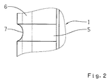
本発明によって提供されるクラッチ体1は、リング状のベース部3を有しており、当該ベース部3には、摩擦面19を有する外側コーン部4が一体的に形成されている。外側コーン部4の摩擦面19は、複数の軸方向に延びる低凹部5を有している。外側コーン部4の径方向内側には、軸から対応する孔を通って供給される油を収集するための、リング状の油収集溝6が設けられている。油収集溝6内に集められた油をクラッチ体1の外側コーン部4の摩擦面19に送るために、外側コーン部4の前方側に、凹部7が径方向に設けられている。当該凹部7は、径方向の切欠凹部として、全周に亘って分布するように配置される。これは、図2から理解できる。
The
当該前方凹部7は、油収集溝6を、低凹部5と接続する。これにより、油収集溝6に集められた油が、遠心力によって、凹部7を介して低凹部5へと到達することができる。軸方向に延びる低凹部5によって、当該油は、外側コーン部4の全体の摩擦面19を濡らすことができる。
The
この実施の形態は、とりわけ、クラッチ体1が鋼鉄(スチール)製の摩擦面19を有すると共に同期リング8がモリブデン製の摩擦ライニング9を有するという同期装置において、利用され得る。
This embodiment can be used, inter alia, in a synchronizer in which the
図3及び図4には、同期装置のための同期リング8の、可能性ある第1の実施の形態が示されている。この同期リング8は、リング状のベース部10を有しており、当該ベース部10には、内側コーン部11が一体的に形成されている。当該内側コーン部11の上面には、摩擦ライニング9が設けられている。図3及び図4では、同期リング8の摩擦ライニング9のみが図示されている。図3は、同期リング8の、平坦に展開された摩擦ライニング9を示している。
3 and 4 show a possible first embodiment of a
この実施の形態では、摩擦ライニング9はリング状に形成されており、各端面領域において、複数の軸方向に延びる溝12、12’、13、13’を有している。溝12、12’及び溝13、13’は、それらが摩擦ライニング9の中央に配置されたリング溝14に到達できるような寸法である長さを有している。各溝12、12’の出口部20、20’は、図3に破線で示されるように、長手方向断面において所定の半径の弓形を有している。もっとも、他の形状も可能である。
In this embodiment, the friction lining 9 is formed in a ring shape, and has a plurality of axially extending
特に図4から明らかなように、各溝12、12’、13、13’の深さは、それらが摩擦ライニング9の厚さと実質的に等しい、という寸法にされる。さらに、溝12、12’は、それぞれ、摩擦ライニング9の対向する端面の溝13、13’に対して、オフセットされて配置されている。摩擦リング8の摩擦ライニング9の当該パターン例によれば、油は、それぞれ、前方側に配置された溝12、12’に入り込み、リング溝14内を接線方向に輸送されて、更に溝13、13’を通って流出する。摩擦リング8の摩擦ライニング9に対するクラッチ体1の接線方向の相対移動により、摩擦面は、同期プロセス中に濡らされて冷却される。従って、リング溝14は、接続された溝12、12’、13、13’によって、油流フラッシング(Oeldurchspuelung)が可能であり、摩擦リング8とクラッチ体1の摩擦面における熱排出の改良が可能である。
As is particularly apparent from FIG. 4, the depth of each
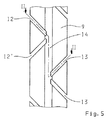
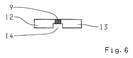
図5及び図6には、同期リング8の第2の実施の形態が示されている。この実施の形態では、図3及び図4による第1の実施の形態とは異なって、摩擦ライニング9が、当該摩擦ライニング9の各々の端面において、傾斜して延びる溝12、12’、13、13’を有している。この場合、隣接する各2つの溝12、12’ないし13、13’は、互いに鏡像対称に配置されている。このパターン例では、以下の利点が得られる。すなわち、傾斜して延びる溝12、12’、13、13’を通って、同期リング8の回転方向に依存しないで、当該溝12、12’、13、13’内に油がほとんど導入される。この供給効果によって、当該溝12、12’、13、13’を通る油の流量が増大して、冷却が更に改善される。
5 and 6 show a second embodiment of the
図7及び図8には、同期リング8の第3の実施の形態が示されている。図7は、同期リング8、クラッチ体1、及び、同期体15を有する同期装置例の部分図である。この実施の形態では、同期リング8は、その内側コーン部11において、複数の軸方向溝16を有している。当該軸方向溝16は、内側コーン部11の全周に亘って、互いに所定の間隔で分布するように配置されている。
7 and 8 show a third embodiment of the
軸方向溝16は、摩擦ライニング9の上方に設けられている。これは、図7からも図8からも明らかである。軸方向溝16は、摩擦ライニング9の適用の前に、好適なプレス方法によって製造され得る。特に図8から明らかなように、摩擦ライニング9は、軸方向溝16の間のブリッジ領域によってのみ、支持されている。これにより、摩擦ライニング9が軸方向溝16によって冷却される、ということが可能である。軸方向溝16には、例えば、クラッチ体1の不図示の油収集溝6からの油が供給される。この態様では、油は、前方側で軸方向溝16内に入り込むことができ、当該軸方向溝16を通って流れることができる。これにより、摩擦ライニング9は冷却され、発生する熱は油によって除去される。
The
好ましくは、軸方向溝16は、テーパ状(コーン状)のコースを有する。この場合、遠心力に基づいて、軸方向溝16内でポンプ効果が得られる。このことは、油の流量を更に高めて、冷却効果を増大させる。
Preferably, the
図9及び図10には、同期リング8の第4の実施の形態が示されている。このパターン例では、同期リング8の内側コーン部11がリング溝17を有している。リング溝17は、内側コーン部11の上面の略中央に配置されている。リング溝17は、摩擦ライニング9内を軸方向に延びる溝18、18’によって少なくとも到達されている。この態様で、油は、前方側の溝18からリング溝17内に至ることができ、内側の溝18’を通って摩擦帯から流出することができる。この実施の形態によっても、同期リング8の摩擦ライニング9の最適な冷却が保証される。
9 and 10 show a fourth embodiment of the
Claims (8)
当該同期リング(8)には、内側コーン部(11)が一体的に形成されており、
当該内側コーン部(11)には、摩擦ライニング(9)が設けられており、
前記内側コーン部(11)は、少なくとも一つのリング溝(17)を有しており、
前記リング状の摩擦ライニング(9)は、各端面において、全周に亘って分布するように配置された複数の軸方向溝(18、18’)を有しており、
当該軸方向溝(18、18’)は、それぞれ、前記リング溝(17)と流体的に接続されており、
前記摩擦ライニング(9)の両端面から始まる溝(18、18’)の各々は、周方向に互いにオフセットされた位置に配置されている
ことを特徴とする同期リング。 A synchronization ring of a synchronization device having a ring-shaped base (10),
The synchronization ring (8) is integrally formed with an inner cone portion (11).
The inner cone part (11) is provided with a friction lining (9),
The inner cone part (11) has at least one ring groove (17),
The ring-shaped friction lining (9) has a plurality of axial grooves (18, 18 ′) arranged so as to be distributed over the entire circumference at each end face,
The axial grooves (18, 18 ′) are fluidly connected to the ring grooves (17), respectively .
The synchronizing ring, wherein the grooves (18, 18 ') starting from both end faces of the friction lining (9) are arranged at positions offset from each other in the circumferential direction .
ことを特徴とする請求項1に記載の同期リング。 The synchronizing ring according to claim 1 , wherein the ring groove (17) extends in the center of the upper surface of the inner cone part (11).
ことを特徴とする請求項1または2に記載の同期リング。 Synchronous ring according to claim 1 or 2 , characterized in that the depth of each groove (18, 18 ') is equal to the thickness of the friction lining (9).
ことを特徴とする請求項1乃至3のいずれかに記載の同期リング。 Outlet portion of each groove (18, 18 ') (21), in longitudinal section, the synchronizing ring according to any one of claims 1 to 3, characterized in that it is arcuate.
ことを特徴とする請求項1乃至4のいずれかに記載の同期リング。 Each groove (18, 18 ') the length of the said groove (18, 18' any of claims 1 to 4, characterized in that) reaches the ring groove (17), it is dimensioned as A synchronization ring as described in Crab.
ことを特徴とする請求項1乃至5のいずれかに記載の同期リング。 Organic material, synchronizing ring according to any one of claims 1 to 5, characterized in that provided as the friction lining of the synchronizing ring (8) (9).
ことを特徴とする請求項6に記載の同期リング。 7. Synchronous ring according to claim 6 , characterized in that carbon is provided as a material for the friction lining (9).
リング状のベース部(3)を有する、同期装置のためのクラッチ体(1)であって、
当該クラッチ体(1)には、外側コーン部(4)が一体的に形成されており、
当該外側コーン部(4)の摩擦面(19)は、油分配のための複数の軸方向に延びる溝を有しており、
当該外側コーン部(4)は、径方向内側で周回する油収集溝(6)を有しており、
当該外側コーン部(4)は、径方向に少なくとも一つの前方凹部(7)を有しており、
当該前方凹部(7)は、前記油収集溝(6)を、それぞれ、油供給のための割り当てられた軸方向に延びる溝に接続している、一つの割り当てられたクラッチ体(1)と、
請求項1乃至7のいずれかに記載された、少なくとも一つの同期リング(8)と、
を備えたことを特徴とする同期装置。 A synchronization device for synchronizing idle gears on the shaft of an automobile transmission,
A clutch body (1) for a synchronizer having a ring-shaped base (3),
The clutch body (1) is integrally formed with an outer cone (4).
The friction surface (19) of the outer cone part (4) has a plurality of axially extending grooves for oil distribution,
The outer cone part (4) has an oil collecting groove (6) that circulates radially inside,
The outer cone part (4) has at least one forward recess (7) in the radial direction,
The front recess (7) has one assigned clutch body (1) , each connecting the oil collecting groove (6) to an assigned axially extending groove for oil supply ;
請 Motomeko according to any one of 1 to 7, and at least one synchronizing ring (8),
A synchronization device comprising:
Applications Claiming Priority (3)
| Application Number | Priority Date | Filing Date | Title |
|---|---|---|---|
| DE102007010764A DE102007010764A1 (en) | 2007-03-06 | 2007-03-06 | Coupling body and synchronizer ring for a synchronizer |
| DE102007010764.3 | 2007-03-06 | ||
| PCT/EP2008/052138 WO2008107315A2 (en) | 2007-03-06 | 2008-02-21 | Clutch body and synchronizer ring for a synchronization device |
Publications (3)
| Publication Number | Publication Date |
|---|---|
| JP2010520429A JP2010520429A (en) | 2010-06-10 |
| JP2010520429A5 JP2010520429A5 (en) | 2011-03-03 |
| JP5283637B2 true JP5283637B2 (en) | 2013-09-04 |
Family
ID=39345479
Family Applications (1)
| Application Number | Title | Priority Date | Filing Date |
|---|---|---|---|
| JP2009552159A Expired - Fee Related JP5283637B2 (en) | 2007-03-06 | 2008-02-21 | Clutch body and synchronization ring for synchronizer |
Country Status (6)
| Country | Link |
|---|---|
| EP (1) | EP2118508B1 (en) |
| JP (1) | JP5283637B2 (en) |
| CN (1) | CN101622466B (en) |
| AT (1) | ATE520890T1 (en) |
| DE (1) | DE102007010764A1 (en) |
| WO (1) | WO2008107315A2 (en) |
Families Citing this family (13)
| Publication number | Priority date | Publication date | Assignee | Title |
|---|---|---|---|---|
| DE102008046916B4 (en) * | 2008-09-12 | 2020-03-12 | Volkswagen Ag | Synchronizer for a motor vehicle |
| DE102011103344A1 (en) * | 2011-05-27 | 2012-11-29 | PMG Füssen GmbH | METHOD FOR PRODUCING A COMPONENT WITH A REBEL TAG |
| DE102011120343B4 (en) * | 2011-11-30 | 2016-03-31 | Getrag Getriebe- Und Zahnradfabrik Hermann Hagenmeyer Gmbh & Cie Kg | Method for producing a coupling body and coupling body for a synchronizer |
| CN102425619B (en) * | 2012-01-01 | 2013-03-27 | 赵孝民 | Synchronous conical hub |
| DE102012221716A1 (en) * | 2012-11-28 | 2014-05-28 | Schaeffler Technologies Gmbh & Co. Kg | Synchronizer of a motor vehicle gear change transmission |
| DE102013215617C5 (en) | 2013-08-08 | 2018-07-19 | Schaeffler Technologies AG & Co. KG | Coupling body of a synchronizing device |
| DE102015212043A1 (en) | 2015-06-29 | 2016-12-29 | Zf Friedrichshafen Ag | Method and device for joining a shaft-hub connection |
| DE102015214017A1 (en) | 2015-07-24 | 2017-01-26 | Zf Friedrichshafen Ag | Method and device for determining a state of wear of a synchronizer ring and agricultural machine |
| DE102016113422A1 (en) | 2016-07-20 | 2018-01-25 | Getrag Getriebe- Und Zahnradfabrik Hermann Hagenmeyer Gmbh & Cie Kg | Friction ring and multi-cone synchronous clutch |
| CN106224401A (en) * | 2016-08-31 | 2016-12-14 | 重庆铁马工业集团有限公司 | A kind of synchromesh cone increases conical surface lubricating method |
| EP3473879B1 (en) * | 2017-10-17 | 2020-09-30 | Ningbo Geely Automobile Research & Development Co. Ltd. | A synchronizing ring |
| EP3708860B1 (en) * | 2019-03-13 | 2021-08-04 | Ningbo Geely Automobile Research & Development Co. Ltd. | A synchronizing ring |
| EP3748184B1 (en) * | 2019-06-05 | 2023-01-25 | Ningbo Geely Automobile Research & Development Co., Ltd. | A synchronizing ring |
Family Cites Families (26)
| Publication number | Priority date | Publication date | Assignee | Title |
|---|---|---|---|---|
| DE2008945A1 (en) * | 1969-04-08 | 1970-11-05 | Ford-Werke AG, 5000 Köln-Deutz | Gear unit for transmissions, in particular for motor vehicles |
| DE2055345A1 (en) | 1970-11-11 | 1972-05-18 | Zahnradfabrik Friedrichshafen | Synchronizing ring in manual transmissions |
| JPS536753Y2 (en) * | 1973-05-09 | 1978-02-21 | ||
| JPS5139152U (en) * | 1974-09-19 | 1976-03-24 | ||
| DE2744994C2 (en) | 1977-10-06 | 1985-08-29 | Stieber Division Der Borg-Warner Gmbh, 6900 Heidelberg | Process for the production of a synchronizing ring |
| DE3113650C2 (en) * | 1981-04-04 | 1989-02-02 | Klöckner-Humboldt-Deutz AG, 5000 Köln | Synchronizing device, in particular for the gearbox of a motor vehicle |
| JPS59187114A (en) | 1983-04-06 | 1984-10-24 | Kyowa Gokin Kk | Synchronous ring in vehicle transmission device |
| DE3417813C1 (en) | 1984-05-14 | 1985-06-05 | Sinterstahl GmbH, 8958 Füssen | Use of sintered friction linings in friction clutches or brakes |
| US4878282A (en) * | 1987-09-04 | 1989-11-07 | Borg-Warner Automotive Gmbh | Method for the production of friction plates, synchronizing blocker rings or similar structures |
| JPH0171228U (en) * | 1987-10-31 | 1989-05-12 | ||
| JPH0241723U (en) * | 1988-09-14 | 1990-03-22 | ||
| DE4017142A1 (en) * | 1990-05-28 | 1991-12-05 | Kloeckner Humboldt Deutz Ag | SYNCHRONIZING DEVICE FOR GEAR GEAR |
| JP2605890Y2 (en) * | 1993-05-13 | 2000-08-21 | 日産ディーゼル工業株式会社 | Transmission synchronization device |
| JP3781811B2 (en) * | 1995-09-22 | 2006-05-31 | Gkn ドライブライン トルクテクノロジー株式会社 | Differential limiter |
| JPH09119504A (en) * | 1995-10-26 | 1997-05-06 | Nsk Warner Kk | Lock-up clutch used for torque converter |
| JPH09144773A (en) * | 1995-11-20 | 1997-06-03 | Kinousei Mokushitsu Shinsozai Gijutsu Kenkyu Kumiai | Synchronizer ring provided with layer of friction material made of wood ceramics |
| JPH11190362A (en) * | 1997-12-26 | 1999-07-13 | Nippon Piston Ring Co Ltd | Synchronizer ring |
| FR2789143B1 (en) * | 1999-01-29 | 2001-03-02 | Valeo | DEVICE IMPLEMENTING FRICTION IN A LIQUID MEDIUM AND COMPRISING A FRICTION PAD WITH CONTROLLED POROSITY |
| DE10036087B4 (en) * | 2000-07-25 | 2009-10-01 | Schaeffler Kg | Gear wheel with a coupling body |
| JP2002235772A (en) * | 2001-02-13 | 2002-08-23 | Kyowa Metal Work Co Ltd | Method of affixing friction member for cone clutch |
| JP2002242954A (en) * | 2001-02-14 | 2002-08-28 | Aisin Aw Co Ltd | Frictional disk |
| CN1802518B (en) * | 2003-06-10 | 2010-04-28 | 奥依列斯工业株式会社 | Synchronizer ring |
| WO2005036006A1 (en) * | 2003-10-02 | 2005-04-21 | Euroflamm Gmbh | Friction material facing and method for providing such friction material facing |
| AT502647B1 (en) * | 2004-01-15 | 2007-05-15 | Miba Sinter Austria Gmbh | SYNCHRONIZING RING FOR A GEAR CHANGE GEAR |
| JP4593983B2 (en) * | 2004-06-25 | 2010-12-08 | Udトラックス株式会社 | Gearbox synchronizer |
| JP2006009953A (en) * | 2004-06-25 | 2006-01-12 | Nissan Diesel Motor Co Ltd | Synchronizer for transmission |
-
2007
- 2007-03-06 DE DE102007010764A patent/DE102007010764A1/en not_active Withdrawn
-
2008
- 2008-02-21 CN CN2008800068026A patent/CN101622466B/en not_active Expired - Fee Related
- 2008-02-21 EP EP08709168A patent/EP2118508B1/en not_active Not-in-force
- 2008-02-21 AT AT08709168T patent/ATE520890T1/en active
- 2008-02-21 JP JP2009552159A patent/JP5283637B2/en not_active Expired - Fee Related
- 2008-02-21 WO PCT/EP2008/052138 patent/WO2008107315A2/en active Application Filing
Also Published As
| Publication number | Publication date |
|---|---|
| WO2008107315A3 (en) | 2008-12-18 |
| DE102007010764A1 (en) | 2008-09-11 |
| WO2008107315A2 (en) | 2008-09-12 |
| CN101622466B (en) | 2011-10-12 |
| CN101622466A (en) | 2010-01-06 |
| EP2118508B1 (en) | 2011-08-17 |
| ATE520890T1 (en) | 2011-09-15 |
| EP2118508A2 (en) | 2009-11-18 |
| JP2010520429A (en) | 2010-06-10 |
Similar Documents
| Publication | Publication Date | Title |
|---|---|---|
| JP5283637B2 (en) | Clutch body and synchronization ring for synchronizer | |
| JP2010520429A5 (en) | ||
| US7455162B2 (en) | Friction lining plates | |
| JP2017503132A (en) | Friction-type shift element for vehicle transmission | |
| US8061497B2 (en) | Disk clutch or multiple disk brake comprising a multi-part disk carrier | |
| CN103790994A (en) | Three-conical-face synchronizer with lubricating oil way | |
| CN203756789U (en) | Three-conical-surface synchronizer with lubricant passage way | |
| JP2010156462A (en) | Clutch support section | |
| JP6879994B2 (en) | Friction type shift element for vehicle transmission | |
| JP2009052739A (en) | Synchronous ring for synchronizing device, friction lining material, and manufacturing method of synchronous ring | |
| CA2591945C (en) | A sintered clutch ring | |
| JP7346509B2 (en) | Friction element for friction type shift element for vehicle transmission | |
| CN104235322B (en) | Shaft device for variator | |
| JP4593983B2 (en) | Gearbox synchronizer | |
| JP2006009953A (en) | Synchronizer for transmission | |
| JP2008106929A (en) | Driving force transmission | |
| JP6467268B2 (en) | Planetary gear mechanism | |
| JP4832698B2 (en) | Automatic transmission | |
| CN107740822A (en) | One kind combines conical ring | |
| JP4884683B2 (en) | Seal member cooling structure and transmission multi-plate clutch structure | |
| JP2005155703A (en) | Conical clutch of synchronizer for transmission | |
| JPH0746817Y2 (en) | Lubrication device for synchronous mechanism in transmission | |
| JP2018059600A (en) | Engagement device of transmission | |
| JP2005344749A (en) | Wet friction plate | |
| JP2023551274A (en) | Wet multi-plate clutch |
Legal Events
| Date | Code | Title | Description |
|---|---|---|---|
| A521 | Request for written amendment filed |
Free format text: JAPANESE INTERMEDIATE CODE: A523 Effective date: 20110113 |
|
| A621 | Written request for application examination |
Free format text: JAPANESE INTERMEDIATE CODE: A621 Effective date: 20110113 |
|
| RD03 | Notification of appointment of power of attorney |
Free format text: JAPANESE INTERMEDIATE CODE: A7423 Effective date: 20111117 |
|
| RD04 | Notification of resignation of power of attorney |
Free format text: JAPANESE INTERMEDIATE CODE: A7424 Effective date: 20120411 |
|
| A977 | Report on retrieval |
Free format text: JAPANESE INTERMEDIATE CODE: A971007 Effective date: 20121113 |
|
| A131 | Notification of reasons for refusal |
Free format text: JAPANESE INTERMEDIATE CODE: A131 Effective date: 20121120 |
|
| A521 | Request for written amendment filed |
Free format text: JAPANESE INTERMEDIATE CODE: A523 Effective date: 20130219 |
|
| A01 | Written decision to grant a patent or to grant a registration (utility model) |
Free format text: JAPANESE INTERMEDIATE CODE: A01 Effective date: 20130521 |
|
| A61 | First payment of annual fees (during grant procedure) |
Free format text: JAPANESE INTERMEDIATE CODE: A61 Effective date: 20130528 |
|
| LAPS | Cancellation because of no payment of annual fees |