JP5279653B2 - Image tracking device, image tracking method, and computer program - Google Patents
Image tracking device, image tracking method, and computer program Download PDFInfo
- Publication number
- JP5279653B2 JP5279653B2 JP2009183629A JP2009183629A JP5279653B2 JP 5279653 B2 JP5279653 B2 JP 5279653B2 JP 2009183629 A JP2009183629 A JP 2009183629A JP 2009183629 A JP2009183629 A JP 2009183629A JP 5279653 B2 JP5279653 B2 JP 5279653B2
- Authority
- JP
- Japan
- Prior art keywords
- pixel
- attribute
- adjacent
- tracking
- evaluated
- Prior art date
- Legal status (The legal status is an assumption and is not a legal conclusion. Google has not performed a legal analysis and makes no representation as to the accuracy of the status listed.)
- Expired - Fee Related
Links
Images


Classifications
-
- G—PHYSICS
- G01—MEASURING; TESTING
- G01S—RADIO DIRECTION-FINDING; RADIO NAVIGATION; DETERMINING DISTANCE OR VELOCITY BY USE OF RADIO WAVES; LOCATING OR PRESENCE-DETECTING BY USE OF THE REFLECTION OR RERADIATION OF RADIO WAVES; ANALOGOUS ARRANGEMENTS USING OTHER WAVES
- G01S11/00—Systems for determining distance or velocity not using reflection or reradiation
- G01S11/12—Systems for determining distance or velocity not using reflection or reradiation using electromagnetic waves other than radio waves
-
- G—PHYSICS
- G01—MEASURING; TESTING
- G01S—RADIO DIRECTION-FINDING; RADIO NAVIGATION; DETERMINING DISTANCE OR VELOCITY BY USE OF RADIO WAVES; LOCATING OR PRESENCE-DETECTING BY USE OF THE REFLECTION OR RERADIATION OF RADIO WAVES; ANALOGOUS ARRANGEMENTS USING OTHER WAVES
- G01S3/00—Direction-finders for determining the direction from which infrasonic, sonic, ultrasonic, or electromagnetic waves, or particle emission, not having a directional significance, are being received
- G01S3/78—Direction-finders for determining the direction from which infrasonic, sonic, ultrasonic, or electromagnetic waves, or particle emission, not having a directional significance, are being received using electromagnetic waves other than radio waves
- G01S3/782—Systems for determining direction or deviation from predetermined direction
- G01S3/785—Systems for determining direction or deviation from predetermined direction using adjustment of orientation of directivity characteristics of a detector or detector system to give a desired condition of signal derived from that detector or detector system
- G01S3/786—Systems for determining direction or deviation from predetermined direction using adjustment of orientation of directivity characteristics of a detector or detector system to give a desired condition of signal derived from that detector or detector system the desired condition being maintained automatically
Landscapes
- Physics & Mathematics (AREA)
- Electromagnetism (AREA)
- Engineering & Computer Science (AREA)
- General Physics & Mathematics (AREA)
- Radar, Positioning & Navigation (AREA)
- Remote Sensing (AREA)
- Image Analysis (AREA)
- Studio Devices (AREA)
- Closed-Circuit Television Systems (AREA)
Abstract
Description
本発明は、画像追尾装置、画像追尾方法、及びコンピュータプログラムに関し、特に、画像を用いて対象物を追尾するために用いて好適なものである。 The present invention relates to an image tracking device, an image tracking method, and a computer program, and is particularly suitable for use in tracking an object using an image.
任意の対象物を追尾する方法として、予め記憶したテンプレート画像との一致度の高い領域を探すパターンマッチ法が知られている。また、テンプレート画像を逐次更新することで、現フレームと前フレームとの差分から対象位置を探す相対差分法や、対象物の色や輝度のヒストグラムとの一致度の高い領域を探すヒストグラムマッチ法等も知られている。 As a method for tracking an arbitrary object, a pattern matching method for searching for a region having a high degree of coincidence with a template image stored in advance is known. In addition, a relative difference method that searches for a target position from the difference between the current frame and the previous frame by sequentially updating the template image, a histogram match method that searches for a region having a high degree of coincidence with the histogram of the color and luminance of the target object, etc. Is also known.
パターンマッチ法は、静止物へのサーチに関しては高い精度が実現できる反面、対象物と追尾装置との距離の変化、対象物の回転、追尾装置自体の姿勢変化等、動きのある状況での追尾性能が十分ではない。また、相対差分法は、対象物の前に他の物体が横切ったり、対象が完全にフレームアウトしたりした後に対象物を追尾できなくなる虞がある。また、ヒストグラムマッチ法では、対象物が動いてもある程度対象物を追尾できるが、色や輝度のヒストグラムだけでは対象物を特定する能力が低く、類似する色や輝度が対象物の背景に多く分布する状況では追尾性能が十分ではない。 The pattern matching method can achieve high accuracy when searching for a stationary object, but it can track in a moving situation such as a change in the distance between the object and the tracking device, rotation of the object, or a change in the attitude of the tracking device itself. The performance is not enough. Further, in the relative difference method, there is a possibility that the object cannot be tracked after another object crosses in front of the object or the object is completely out of frame. In addition, the histogram match method can track the object to some extent even if the object moves, but the ability to identify the object is low only with the histogram of color and luminance, and many similar colors and luminance are distributed in the background of the object Tracking performance is not enough in the situation.
このような各種の追尾方式において追尾性能を向上させるために、ヒストマッチ法において、参照領域のヒストグラムと参照領域とは独立した拡張参照領域のヒストグラムとを作成し、これらのヒストグラムを併用する技術がある(特許文献1を参照)。特許文献1には、例えば、参照領域として人物の顔付近のヒストグラムを作成し、拡張参照領域として首付近のヒストグラムを作成することが記載されている。
In order to improve the tracking performance in such various tracking methods, there is a technique of creating a reference region histogram and an extended reference region histogram independent of the reference region and using these histograms together in the histomatch method. (See Patent Document 1).
しかしながら、特許文献1に記載の技術では、ヒストグラムの作成対象領域として、参照領域と、拡張参照領域の相互に独立した2つの領域を設定する必要がある。したがって、拡張参照領域において対象物が隠れてしまうと、追尾性能が落ちてしまうという問題点があった。
本発明は、このような問題点に鑑みてなされたものであり、従来の追尾方式では十分な追尾が実現できなかった状況での追尾性能を向上させることを目的とする。
However, in the technique described in
The present invention has been made in view of such problems, and an object of the present invention is to improve the tracking performance in a situation where sufficient tracking cannot be realized by the conventional tracking method.
本発明の画像追尾装置は、画像に対して設定された追尾対象領域内のそれぞれの画素の属性と、当該画素に隣接する画素の属性とを記憶する記憶手段と、前記画像における追尾対象物を追尾するに際し、前記画像における評価対象の画素の属性と、前記追尾対象領域内の画素の属性とを比較した結果と、当該評価対象の画素に隣接する画素の属性と、当該追尾対象領域内の画素に隣接する画素の属性とを比較した結果に応じて、当該評価対象の画素に評価値を付与する付与手段と、前記付与手段により付与された評価値に基づいて、前記追尾対象領域を変更する変更手段と、を有することを特徴とする。 The image tracking device of the present invention includes a storage unit that stores the attribute of each pixel in a tracking target area set for an image and the attribute of a pixel adjacent to the pixel, and a tracking object in the image. In tracking, the result of comparing the attribute of the pixel to be evaluated in the image with the attribute of the pixel in the tracking target area, the attribute of the pixel adjacent to the pixel to be evaluated, and the attribute in the tracking target area According to the result of comparing the attributes of the pixels adjacent to the pixel, an assigning unit that assigns an evaluation value to the pixel to be evaluated, and the tracking target area is changed based on the evaluation value given by the assigning unit And changing means.
本発明によれば、従来の追尾方式では十分な追尾が実現できなかった状況での追尾性能を向上できる。 ADVANTAGE OF THE INVENTION According to this invention, the tracking performance in the condition where sufficient tracking was not realizable with the conventional tracking system can be improved.
以下、図面を参照しながら、本発明の実施形態を説明する。
(第1の実施形態)
まず、本発明の第1の実施形態を説明する。
図1は、撮像装置の基本構成の一例を示す図である。撮像装置は、静止画像及び動画像の何れも撮像することができる。
図1において、被写体からの光は、絞り、フォーカスレンズ、変倍レンズ、固定レンズを備えた撮像光学系101によって撮像素子102に結像される。撮像素子102は、受光面上に結像された像による光信号を、対応する位置の受光画素毎に電気信号に変換する光電変換素子である。撮像素子102に結像された光は撮像素子102で電気信号に変換され、その電気信号がA/Dコンバータ103でデジタル信号に変換され、画像処理回路104に入力される。
Hereinafter, embodiments of the present invention will be described with reference to the drawings.
(First embodiment)
First, a first embodiment of the present invention will be described.
FIG. 1 is a diagram illustrating an example of a basic configuration of an imaging apparatus. The imaging device can capture both still images and moving images.
In FIG. 1, light from a subject is imaged on an
画像処理回路104は、入力されたデジタル信号(画像データ)に対して画像処理を行う。表示装置105は、撮像装置100の背面に設けられた表示部であり、電子ビューファインダとしての機能を有する。また、表示装置105は、撮像装置100の設定状況を表示したり、撮影後、撮像装置100で作成されたサムネイル画像を表示したりする。撮像光学系制御回路106は、絞りの開口径を変化させたり、フォーカスレンズの移動制御を行ったりする。また、撮像光学系制御回路106は、被写体距離と、変倍レンズ群の位置情報に基づく焦点距離と、絞りの開口径に基づくFナンバとを含むレンズ情報を生成する。システムコントローラ107は、例えばマイクロコンピュータを有し、コンピュータプログラムを実行する等して撮像装置100を統括制御する。画像記録媒体108は、画像データを記録する。
The
本実施形態では、このような構成からなる撮像装置100において、任意の対象物について画像追尾を行う方法の一例について述べる。
図2は、従来の追尾方式では追尾が困難なシーンの例を示す図である。
図2(a)において、画面200の中央付近に位置する動物を追尾対象とする。追尾対象の指定方法は、予め決められた色条件や輝度条件を満たした領域を自動で判別して追尾対象としても、タッチパネル式とした表示装置105において、ユーザが任意の位置をタッチすることで追尾対象を確定してもよい。
In the present embodiment, an example of a method for performing image tracking on an arbitrary object in the
FIG. 2 is a diagram showing an example of a scene that is difficult to track with the conventional tracking method.
In FIG. 2A, an animal located near the center of the
図2では、動物の胴体付近の領域202を追尾対象の領域とした後、動物が他の場所へ移動すると共に、動物の体の向きが変化した場合を示している。このような変化をした場合、図2(a)に示す、追尾対象の領域202の画像と、図2(b)で示す、移動後の動物の胴体付近の領域210の画像とを比較するパターンマッチング法では、動物の追尾は困難なものとなる。また、図2に示すように、追尾対象の領域202の画像のヒストグラム220と、移動後の動物の胴体付近の領域210の画像のヒストグラム222とを比較するヒストグラムマッチ法でも、これらの一致がとれなくなるので、動物の追尾は困難なものとなる。
FIG. 2 shows a case where the
続いて、フローチャートを参照しながら、本実施形態において任意の対象物を追尾する方法の一例を説明する。尚、本実施形態では、システムコントローラ107が以下のフローチャートによる処理を実行する場合を例に挙げて説明するが、その処理の一部又は全部をシステムコントローラ107以外(例えば画像処理回路104)で行うようにしてもよい。
Next, an example of a method for tracking an arbitrary object in the present embodiment will be described with reference to a flowchart. In the present embodiment, the case where the
図3は、対象物を追尾する際の撮像装置の処理の一例を説明するメインフローチャートである。
まず、システムコントローラ107は、追尾対象物の位置とサイズとを確定する(ステップS101)。先に述べたように、自動で追尾対象物を確定する方法や、ユーザが電子ビューファインダから任意の領域を指定して追尾対象物を確定する方法がある。追尾対象物の位置とサイズとが決まった後、システムコントローラ107は、追尾対象領域の色情報と輝度情報とから追尾対象物の認識処理を行う(ステップS102)。
FIG. 3 is a main flowchart for explaining an example of processing of the imaging apparatus when tracking an object.
First, the
図4は、ステップS102の追尾対象物認識処理の一例を説明するフローチャートである。まず、システムコントローラ107は、追尾対象領域のヒストグラム(主ヒストグラム)を作成する(ステップS201)。
図5は、画像と、当該画像の追尾対象領域の画素の一例を示す図である。図5では、ペンギンのシーンをカメラで捉えている画像300において、ペンギンの頭部を追尾対象領域302としてタッチパネルによりユーザが指定することで、追尾対象領域を確定する様子を示している。
FIG. 4 is a flowchart for explaining an example of the tracking target object recognition process in step S102. First, the
FIG. 5 is a diagram illustrating an example of an image and pixels of a tracking target area of the image. FIG. 5 shows a state where the tracking target area is determined by designating the head of the penguin as the tracking
追尾対象領域302は、太線で囲われた領域304であることを示しており、この領域304内外のヒストグラムを作成する。ヒストグラムは、色相ヒストグラムと輝度ヒストグラムとに分かれており、各画素が有彩色画素であるか無彩色画素であるかに応じて、それぞれ色相ヒストグラムと輝度ヒストグラムに分布を取っていく。有彩色画素であるか無彩色画素であるかの判定は、各画素の彩度を閾値と比較することで行う。このとき、追尾対象領域302内と追尾対象領域302外のそれぞれの領域毎にヒストグラムを取る。
The
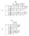
図6は、色相ヒストグラム(有彩色画素のヒストグラム)と(図6(a))と、色相ヒストグラムで分類された画素の平均輝度、平均彩度、及び平均色相を示す平均色相ヒストグラム(図6(b))の一例を示す。また、図7は、輝度ヒストグラム(無彩色画素のヒストグラム)と(図7(a))、輝度ヒストグラムで分類された画素の平均輝度を示す平均輝度ヒストグラム(図7(b))の一例を示す図である。 FIG. 6 shows a hue histogram (histogram of chromatic color pixels) and (FIG. 6A), and an average hue histogram (FIG. 6 (A)) showing the average luminance, average saturation, and average hue of the pixels classified by the hue histogram. An example of b)) is shown. FIG. 7 shows an example of a luminance histogram (achromatic pixel histogram) (FIG. 7A) and an average luminance histogram (FIG. 7B) showing the average luminance of the pixels classified by the luminance histogram. FIG.
有彩色画素は、色相ヒストグラム400に分類(登録)される。システムコントローラ107は、追尾対象領域302内に存在する色相Hue毎に、追尾対象領域内In、追尾対象領域外Outの画素数をカウントしていく。図6では、40°毎の分割単位(分類単位)で色相ヒストグラム400を作成しているが、要求される追尾精度に応じて分割単位を変更してもよい。
無彩色画素は、輝度ヒストグラム440に分類(登録)される。システムコントローラ107は、追尾対象領域302内に存在する輝度Y毎に、追尾対象領域内In、追尾対象領域外Outの画素数をカウントしていく。図7では、40LSB毎の分割単位で輝度ヒストグラム440を作成しているが、要求される追尾精度に応じて分割単位を変更してもよい。
The chromatic color pixels are classified (registered) in the
Achromatic pixels are classified (registered) in the
システムコントローラ107は色相ヒストグラム400及び輝度ヒストグラム440を取った後、追尾対象領域内外の各色相の存在比率Ratio[%](=(追尾対象領域内の画素数/追尾対象領域外の画素数)×100)を算出する。例えば、Pink色の色相は、追尾対象領域302内に2画素、追尾対象領域302外に13画素あるので、その存在比率Ratioは15%(=(2/13)×100)となる。ただし、追尾対象領域内の画素数が1以上であって追尾対象領域外の画素数が0の場合は、存在比率Ratioを100とする。
尚、この存在比率Ratioは、必ずしもこのようにする必要はなく、例えば、「存在比率Ratio[%]=[追尾対象領域内の画素数/(追尾対象領域内の画素数+追尾対象領域外の画素数)]×100」としてもよい。
After taking the
The existence ratio Ratio does not necessarily need to be in this manner. For example, “existence ratio Ratio [%] = [number of pixels in the tracking target area / (number of pixels in the tracking target area + the number outside the tracking target area]” The number of pixels)] × 100 ”.
また、システムコントローラ107は、色相の分布を取る処理と共に、追尾対象領域302内のヒストグラムの分割単位毎に、当該分割単位に分類された画素の平均輝度AveY、平均彩度AveChroma、及び平均色相AveHueを算出する。
例えば、図6(a)に示す色相ヒストグラム400では、Yellowは、追尾対象領域302内に3画素ある。よって、図6(b)に示す平均色相ヒストグラム420では、この3画素の平均輝度AveYが153LSB、平均彩度AveChromaが55LSB、平均色相AveHueが113°であることを示している。
同様に、図7(a)に示す輝度ヒストグラム440では、無彩色のWhiteは、追尾対象領域302内に3画素ある。よって、図7(b)に示す平均輝度ヒストグラム480では、この3画素の平均輝度が210LSBであることを示している。
In addition to the process of calculating the hue distribution, the
For example, in the
Similarly, in the
このように、追尾対象領域302内の有彩色画素の情報として、色相ヒストグラム400と、色相ヒストグラム400で分類される画素の平均輝度AveY、平均彩度AveChroma及び平均色相AveHue(平均色相ヒストグラム420)が得られる。更に、図5に示した追尾対象領域302内の無彩色画素の情報として、輝度ヒストグラム440と、当該輝度ヒストグラム440で分類される画素の平均輝度AveY(平均輝度ヒストグラム480)が得られる。
尚、以下の説明では、色相ヒストグラム400、平均色相ヒストグラム420、輝度ヒストグラム440、及び平均輝度ヒストグラム480を必要に応じて主ヒストグラムと総称する。
As described above, as information on the chromatic color pixels in the
In the following description, the
図4の説明に戻り、システムコントローラ107は、主ヒストグラムの色相ヒストグラム400、輝度ヒストグラム440のそれぞれにおいて分割単位に分類された各画素に隣接する画素集合のヒストグラム500、520を作成する(ステップS202)。尚、以下の説明では、このヒストグラム500、520を必要に応じて隣接ヒストグラムと称する。
図8、図9は、隣接ヒストグラムの作成対象となる画素の第1、第2の例を概念的に示す図である。図6、図7に示したように、追尾対象領域302内の有彩色の情報として、Pink、Yellow、Green、Blue2の4つ、無彩色の情報としてBlack0、Black1、Gray2、Whiteの4つ、計8つの分布が取れたものとする。この8つに分布した各画素の隣接画素の様子が、図8、図9に示されている。
Returning to the description of FIG. 4, the
FIG. 8 and FIG. 9 are diagrams conceptually showing first and second examples of pixels for which an adjacent histogram is to be created. As shown in FIG. 6 and FIG. 7, the chromatic information in the
図8(a)では、2つのPink画素550、552の隣接画素を、円で囲って示している。Pink画素550の周囲には、Blue2が1画素、Gary2が1画素、Black1が1画素、Pinkが2画素、Whiteが1画素、Greenが2画素、の計8画素が分布している。Pink画素552の周囲には、Gray2が1画素、Black1が3画素、Black0が1画素、Whiteが1画素、Greenが1画素、Pinkが1画素、の計8画素が分布している。このPink画素550、552の周囲にある延べ16画素を、Pink画素に隣接する画素集合として、ヒストグラムを取る。
In FIG. 8A, adjacent pixels of the two
同様に図8(b)では3つのYellow画素554、556、558に隣接する延べ24画素、図8(c)では2つのGreen画素560、562に隣接する延べ16画素、図8(d)では1つのBlue2画素564に隣接する述べ8画素の様子を示す。
また、図9(a)〜(d)では、無彩色の画素の隣接画素の様子として、それぞれBlack0、Black1、Gray2、White画素の隣接画素の様子を示している。
Similarly, in FIG. 8B, a total of 24 pixels adjacent to the three
FIGS. 9A to 9D show states of adjacent pixels of Black0, Black1, Gray2, and White pixels, respectively, as the states of adjacent pixels of achromatic pixels.
本実施形態では、図5に示した追尾対象領域304に対し、主ヒストグラムはその追尾対象領域304内の画素のヒストグラムを取るようにする。これに対し、隣接関係については、追尾対象領域304よりも一回り広い領域を対象として認識するようにしている。こうすることで追尾対象と背景との関係も含めた隣接関係を取れるため、良好な追尾結果が得られる場合がある。ただし、両者を同じ領域を参照するようにしてもよい。
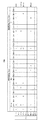
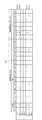
システムコントローラ107は、図8、図9で示した主ヒストグラムの各分割単位に分類された各画素の隣接画素からなる画素集合のヒストグラム(隣接ヒストグラム)を、主ヒストグラムと相互に対応させ、図10、図11に示す形式で記憶する。
In the present embodiment, for the tracking
The
図10は、主ヒストグラムの色相ヒストグラムに対応する隣接ヒストグラム、図11は主ヒストグラムの輝度ヒストグラムに対応する隣接ヒストグラムを示している。隣接ヒストグラムにおいて、隣接する画素の分布情報として、有彩色Colorの画素から輝度Y、彩度Chroma、色相Hueを抽出してそれぞれの分布を取り、無彩色Colorlessの画素から輝度Yの分布を取れるようになっている。
以上のように本実施形態では、例えば、ステップS201、S202の処理を行うことにより記憶手段の一例が実現される。また、例えば、ステップS201の処理を行うことにより主ヒストグラムの記憶手段の一例が実現され、ステップS202の処理を行うことにより隣接ヒストグラムの記憶手段の一例が実現される。
また、本実施形態では、例えば、評価対象の画素が有彩色である場合には、第1の属性は色相Hueとなり、評価対象の画素が無彩色である場合には、第1の属性は輝度Yとなるようにしている。また、本実施形態では、例えば、評価対象の画素に隣接する画素が有彩色である場合には、第2の属性は色相Hue、彩度Chroma、及び輝度Yとなり、評価対象の画素に隣接する画素が無彩色である場合には、第2の属性は輝度Yとなるようにしている。
FIG. 10 shows an adjacent histogram corresponding to the hue histogram of the main histogram, and FIG. 11 shows an adjacent histogram corresponding to the luminance histogram of the main histogram. In the adjacent histogram, luminance Y, saturation Chroma, and hue Hue are extracted from the pixels of chromatic color as the distribution information of adjacent pixels, and the respective distributions are taken, and the distribution of luminance Y can be obtained from the pixels of achromatic Colorless. It has become.
As described above, in the present embodiment, for example, an example of the storage unit is realized by performing the processing of steps S201 and S202. Further, for example, an example of a main histogram storage unit is realized by performing the process of step S201, and an example of an adjacent histogram storage unit is realized by performing the process of step S202.
In the present embodiment, for example, when the pixel to be evaluated is a chromatic color, the first attribute is hue Hue, and when the pixel to be evaluated is achromatic, the first attribute is a luminance. I try to be Y. In the present embodiment, for example, when a pixel adjacent to the pixel to be evaluated has a chromatic color, the second attributes are hue Hue, saturation Chroma, and luminance Y, and are adjacent to the pixel to be evaluated. When the pixel is achromatic, the second attribute is luminance Y.
以上のようにして図4のフローチャートに示す追尾対象物認識処理(主ヒストグラムの取得と、隣接ヒストグラムの取得)が終了すると、システムコントローラ107は、追尾対象物を追尾することが可能かどうかの判定処理を行う(図3のステップS103)。図12は、ステップS103の追尾可否判定処理の一例を説明するフローチャートである。
まず、システムコントローラ107は、図4、図6、及び図7で示したように、追尾対象領域の内外において、色相ヒストグラムと輝度ヒストグラムとからなる主ヒストグラムを取る(ステップS301、S302)。
When the tracking object recognition process (main histogram acquisition and adjacent histogram acquisition) shown in the flowchart of FIG. 4 is completed as described above, the
First, as shown in FIGS. 4, 6, and 7, the
ここで、図12において、aHistColorTarget(m)は、図6(a)の色相ヒストグラム400における色相Hue毎の追尾対象領域内Inの画素数を示す。aHistYTarget(n)は、図7(a)の輝度ヒストグラム440における輝度Y毎の追尾対象領域内Inの画素数を示す。aHistColorOther(m)は、図6(a)の色相ヒストグラム400における色相Hue毎の追尾対象領域外Outの画素数を示す。aHistYOther(n)は、図7(a)の輝度ヒストグラム440における輝度Y毎の追尾対象領域外Outの画素数を示す。また、システムコントローラ107は、これらの値から、図6(b)に示す平均色相ヒストグラムと、図7(b)に示す平均輝度ヒストグラムも作成する。
Here, in FIG. 12, aHistColorTarget (m) indicates the number of pixels in the tracking target area In for each hue Hue in the
次に、システムコントローラ107は、色相ヒストグラムの分割単位ごとに、追尾対象領域内に画素が分布しているか否かを判定する(ステップS303)。aHistColorTarget(i)は、色相ヒストグラム400におけるある色相Hue(i)に対応する追尾対象領域内Inの画素数を示す値である。追尾対象領域内にその色相Hue(i)の1以上の画素が存在している場合、システムコントローラ107は、その色相Hue(i)に対して追尾対象領域の内外の存在比率Ratioを算出する(ステップS304)。追尾対象領域内外の各色相の存在比率Ratioについては、図6(a)、図7(a)を参照して示した通りである。つまり、システムコントローラ107は、その色相Hue(i)における追尾対象領域内Inの画素数(aHistColorTarget(i))を追尾対象領域外Outの画素数(aHistColorOther (i))で除した値に100を乗じてこの存在比率Ratioを算出する。ただし、aHistColorTarget(i)が1以上であってaHistColorOther(i)が0の場合は、存在比率Ratioを100とする。
Next, the
次に、システムコントローラ107は、この存在比率Ratioが、所定の色相採用条件となる比率を上回っているか否かを判定する(ステップS305)。この判定の結果、存在比率Ratioが、所定の色相採用条件となる比率を上回っていない場合には、追尾対象と同じ色が背景にも多く分布しており、この色を用いた追尾の実施は精度が低下すると判断される。このため、システムコントローラ107は、高い追尾精度を実現するために、処理対象の色相Hue(i)を"不採用"と判断する(ステップS306)。一方、存在比率Ratioが、所定の色相採用条件となる比率を上回っている場合、システムコントローラ107は、処理対象の色相Hue(i)を"採用"と判断する(ステップS307)。
Next, the
そして、システムコントローラ107は、処理対象となった色相Hue(i)の追尾対象領域内の画素数aHistColorTarget(i)の総数SumOKTargetと、追尾対象領域外の画素数aHistColorOther (i)の総数SumOKOtherを記憶する(ステップS308)。システムコントローラ107は、全ての色相Hue(i)に対して、このステップS303からS308までの処理を繰り返す(ステップS309)。このように本実施形態では、色相ヒストグラムの全ての分割単位の色相Hue(i)に対して採用/不採用のチェックを行うと共に、採用された画素数の総和を記憶する。
Then, the
同様に、輝度ヒストグラムに対しても追尾対象領域の内外の存在比率が、所定の輝度採用条件となる比率を上回っているか否かを判定し、輝度ヒストグラムの分割単位の輝度Y(i)ごとに採用/不採用のチェックを行う(ステップS310〜S316)。なお、ステップS315で求める追尾対象領域内の画素の総数SumOKTarget、追尾対象領域外の画素の総数SumOKOtherは、それぞれ採用された色相Hue(i)の画素数の総和に、採用された輝度Y(i)の画素数を加算して求める値である。よって、最終的に得られる追尾対象領域内の画素の総数SumOKTarget、追尾対象領域外の画素の総数SumOKOtherは、それぞれ採用された色相Hue(i)の画素数と採用された輝度Y(i)の画素数の総和となる。 Similarly, with respect to the luminance histogram, it is determined whether or not the existence ratio inside and outside the tracking target area exceeds the ratio that is a predetermined luminance adoption condition, and for each luminance Y (i) in the luminance histogram division unit. Adoption / non-adoption is checked (steps S310 to S316). Note that the total number of pixels SumOKTarget and the total number of pixels outside the tracking target area SumOKOther obtained in step S315 are the sum of the number of pixels of the employed hue Hue (i). ) Is obtained by adding the number of pixels. Therefore, the total number of pixels in the tracking target area SumOKTarget and the total number of pixels outside the tracking target area SumOKOther that are finally obtained are the number of pixels of the hue Hue (i) adopted and the luminance Y (i) adopted, respectively. This is the total number of pixels.
ここで、"色相採用条件"と"輝度採用条件"は個別に設定できるものとしておく。特に無彩色は有彩色に比べ、追尾対象の特徴と成り得ない場合が多く、輝度採用条件として色相採用条件よりも厳しい採用基準を設けるようにすることができる。また、図示してはいないが、有彩色、無彩色という採用条件設定だけでなく、特定の色や輝度の場合にだけ採用条件を変える形態にしてもよい。また、ステップS303〜S309と、ステップS310〜S316の何れか一方を行わないようにしてもよい。 Here, it is assumed that “hue employment condition” and “brightness employment condition” can be set individually. In particular, an achromatic color is often not a characteristic of a tracking target as compared to a chromatic color, and it is possible to set a stricter adoption standard than a hue adoption condition as a luminance adoption condition. In addition, although not shown, the employment conditions may be changed not only for the adoption conditions of chromatic and achromatic colors but also for specific colors and brightness. Further, any one of steps S303 to S309 and steps S310 to S316 may be omitted.
主ヒストグラムの色相ヒストグラムと輝度ヒストグラムの分割単位ごとに採用するか否かを確認した後、システムコントローラ107は、追尾対象領域内に、採用された有彩色や無彩色の画素がどの程度の割合で存在しているかを判断する(ステップS317)。具体的にシステムコントローラ107は、採用された追尾対象領域内の画素の総数SumOKTargetを枠内の画素数で除した値に100を乗じてこの割合Ratioを算出する。
そして、システムコントローラ107は、この割合Ratioが所定の枠内条件を上回っているか否かを判定する(ステップS318)。この判定の結果、割合Ratioが所定の枠内条件を上回っていない場合、システムコントローラ107は、追尾対象の特徴を十分に捉えることが出来なかったと判断し、追尾不可とする(ステップS319)。
After confirming whether or not to adopt the hue histogram and luminance histogram for each division unit of the main histogram, the
Then, the
一方、割合Ratioが所定の枠内条件を上回っている場合、システムコントローラ107は、追尾対象の特徴を捉えることができたと判断し、採用された有彩色や無彩色の画素が、画面内にどの程度存在しているかの割合を算出する(ステップS320)。具体的にシステムコントローラ107は、追尾対象領域内の画素の総数SumOKTargetと、追尾対象領域外の画素の総数SumOKOtherとを加算した値を全画面の画素数で除した値に100を乗じてこの割合Ratioを算出する。
そして、システムコントローラ107は、この割合Ratioが所定の全画面条件Bを下回っているか否かを判定する(ステップS321)。この判定の結果、割合Ratioが所定の全画面条件Bを下回っていない場合、システムコントローラ107は、追尾対象となる有彩色や無彩色の画素が追尾対象以外の背景領域に多くあり、追尾性能が低下する懸念があるとして追尾不可とする(ステップS319)。
On the other hand, if the ratio Ratio exceeds a predetermined in-frame condition, the
Then, the
一方、割合Ratioが所定の全画面条件Bを下回っている場合、システムコントローラ107は、追尾可能と判断する(ステップS322)。
このように、追尾可能か否かの判断を、色・輝度ごとの単体評価、追尾領域内評価、画面全体評価と、幾重にも渡ってチェックすることで追尾可否を確実に行うことが可能となる。ただし、画面全体評価(ステップS320、S321)については必ずしも行う必要はない。
On the other hand, if the ratio Ratio is less than the predetermined full screen condition B, the
In this way, it is possible to reliably determine whether tracking is possible by checking multiple times, such as individual evaluation for each color and brightness, evaluation within the tracking area, overall screen evaluation, whether or not tracking is possible Become. However, the overall screen evaluation (steps S320 and S321) is not necessarily performed.
図3の説明に戻り、システムコントローラ107は、以上の追尾可否判定処理の結果に基づいて、追尾対象領域を追尾することが可能であるか否かを判定する(ステップS104)。この判定の結果、追尾対象領域を追尾することが可能でない場合には、図3のフローチャートによる処理を終了する。一方、追尾対象領域を追尾することが可能である場合には、追尾ループ処理が開始される。
追尾ループではまず、追尾継続可否判定が行われる(ステップS105)。図13は、ステップS105の追尾継続可否判定処理の一例を説明するフローチャートである。まず、システムコントローラ107は、図6(a)、図7(a)に示したヒストグラムで採用された有彩色及び無彩色の画素が、画面内に存在する割合Ratioを算出する(ステップS401)。具体的にシステムコントローラ107は、図6(a)、図7(a)に示したヒストグラムで採用された有彩色及び無彩色の画素の総数SumOKALLを全画面の画素数で除した値に100を乗じてこの割合Ratioを算出する。この総数SumOKALLは、追尾対象領域内の画素の総数SumOKTargetと、追尾対象領域外の画素の総数SumOKOtherとを加算した値である。
Returning to the description of FIG. 3, the
In the tracking loop, it is first determined whether or not tracking can be continued (step S105). FIG. 13 is a flowchart for explaining an example of the tracking continuability determination process in step S105. First, the
そして、システムコントローラ107は、この割合Ratioが所定の全画面条件Cを下回っているか否かを判定する(ステップS402)。この判定の結果、割合Ratioが所定の全画面条件Cを下回っていない場合、システムコントローラ107は、追尾対象となる有彩色や無彩色の画素が追尾対象以外の背景領域に多くあり、追尾性能が低下する懸念がある判断する。すなわち、システムコントローラ107は、追尾不可と判断する(ステップS403)。一方、割合Ratioが所定の全画面条件Cを下回っている場合、システムコントローラ107は、追尾可能と判断する(ステップS404)。
Then, the
ここで、"全画面条件C"は、図12のステップS321で示した追尾可否の最終判断条件である"全画面条件B"とは別の条件にすることができる。全画面条件Cを全画面条件Bよりも厳しい条件としておくことで、追尾開始後に背景の状況が変化し、追尾対象と同じ色相や同じ輝度の画素が増加してきても、適切に追尾を中断するか否かの判断を行うことができる。また、図13では、"全画面条件C"のまま条件を固定する場合を例に挙げて示しているが、追尾開始からの経過時間に応じて徐々に条件を異ならせる(例えば、厳しくしていく)ようにしてもよい。さらに、図12のステップS318で示した"枠内条件"、ステップS321で示した"全画面条件B"、及び図13のステップS402で示した"全画面条件C"を、追尾対象が色相のみ、輝度のみ、色相と輝度との双方の場合に応じて分けて細分化してもよい。また、特定の色のみ、特定の輝度のみに対する条件をさらに変えるようにしても良い。 Here, the “full-screen condition C” can be a condition different from the “full-screen condition B” that is the final determination condition of the tracking availability shown in step S321 in FIG. By setting the full screen condition C to be stricter than the full screen condition B, even if the background situation changes after the start of tracking and pixels with the same hue and the same brightness as the tracking target increase, tracking is appropriately interrupted. It can be determined whether or not. FIG. 13 shows an example in which the condition is fixed as “full screen condition C”. However, the condition is gradually changed according to the elapsed time from the start of tracking (for example, the condition is made stricter). You may do it. Furthermore, the “target condition” in step S318 in FIG. 12, the “full screen condition B” in step S321, and the “full screen condition C” in step S402 in FIG. In addition, only the luminance may be divided and subdivided depending on both the hue and the luminance. Further, the conditions for only a specific color and only a specific luminance may be further changed.
図3の説明に戻り、システムコントローラ107は、以上の追尾継続可否判定処理の結果に基づいて、追尾対象領域の追尾を継続することが可能であるか否かを判定する(ステップS106)。この判定の結果、追尾対象領域の追尾を継続することが可能でない場合には、図3のフローチャートによる処理を終了する。一方、追尾対象領域の追尾を継続することが可能である場合には、追尾対象の検出処理が行われる(ステップS107)。
図14は、ステップS107の追尾対象検出処理の一例を説明するフローチャートである。追尾対象検出処理は画面全体や、画面内の任意の領域に対してのみ実施することができるが、ここでは画面全体に対して追尾対象検出処理を実施する場合を例に挙げて示す。
Returning to the description of FIG. 3, the
FIG. 14 is a flowchart illustrating an example of the tracking target detection process in step S107. The tracking target detection process can be performed only on the entire screen or an arbitrary area in the screen. Here, a case where the tracking target detection process is performed on the entire screen is described as an example.
図15は、追尾対象検出処理で追尾対象領域を追尾する方法の一例を概念的に示す図である。画面内を追尾する基点や方向や順序も様々に設定することができるが、ここでは図15に示すように、画面左上を基点に水平方向へ探索し、次いで下のラインへ、順次探索する場合を例に挙げて説明する。
まず、システムコントローラ107は、処理対象(評価対象)の画素が、主ヒストグラムに分布した画素に一致するとみなせるか否かを判定する(ステップS501)。具体的にシステムコントローラ107は、処理対象の画素が、追尾対象領域内に存在するものとして図6(a)、図7(a)に示した主ヒストグラムに記憶された有彩色や無彩色であるか否かをチェックする。
FIG. 15 is a diagram conceptually illustrating an example of a method of tracking a tracking target area in the tracking target detection process. The base point, direction, and order of tracking in the screen can be set in various ways, but here, as shown in FIG. 15, when searching in the horizontal direction starting from the upper left corner of the screen and then sequentially searching to the lower line Will be described as an example.
First, the
また、システムコントローラ107は、処理対象の画素が、図6(b)、図7(b)に示した平均ヒストグラムに記憶した各平均(平均輝度、平均彩度、平均色相)に対して所定の範囲内に入っているか否かをチェックする。この判定の結果、処理対象の画素が、主ヒストグラムに分布した画素に一致するとみなせない場合には、後述するステップS506に進む。一方、処理対象の画素が、主ヒストグラムに分布した画素に一致するとみなせる場合、システムコントローラ107は、その画素の位置に対してポイントを付加する(ステップS502)。
In addition, the
図16は、追尾対象を検出するために探索される画素にポイントを付与する方法の一例を概念的に示す図である。図16(a)に示すように、処理対象の画素650が主ヒストグラムの有彩色と一致する場合に、その画素650に1ポイントが付加される。一方、図16(b)に示すように、処理対象の画素650が主ヒストグラムの無彩色と一致する場合に、その画素660に0ポイントが付加される(ポイントが付加されない)。あるいは、処理対象の画素650が主ヒストグラムの有彩色と一致する場合には、2ポイントを付加し、処理対象の画素650が主ヒストグラムの無彩色と一致する場合には、有彩色と一致する場合よりも小さな1ポイントを付加するようにしてもよい。
FIG. 16 is a diagram conceptually illustrating an example of a method for assigning points to pixels searched for detecting a tracking target. As shown in FIG. 16A, when the
次に、システムコントローラ107は、処理対象の画素に隣接する画素が、隣接ヒストグラムに分布した画素に一致するとみなせるか否かを判定する(ステップS503)。例えば、システムコントローラ107は、主ヒストグラムとの一致が取れた画素に関し、図15に示すように、処理対象の画素610の周辺の8画素が、図10、図11で示した隣接ヒストグラムと一致するとみなせるか否かを判定する。この判定の結果、処理対象の画素に隣接する画素が、隣接ヒストグラムに分布した画素に一致するとみなせない場合には、後述するステップS505に進む。一方、処理対象の画素に隣接する画素が、隣接ヒストグラムに分布した画素に一致するとみなせた場合、システムコントローラ107は、その画素の位置に対してポイントを付加する(ステップS504)。
Next, the
具体例を説明すると、図16(c)に示すように、主ヒストグラムと一致した有彩色の画素の隣に、隣接ヒストグラムに分布する画素であって、当該有彩色の色相と異なる色相の有彩色の画素652がある場合、5ポイントが付加される。また、図16(c)に示すように、主ヒストグラムと一致した有彩色の画素の隣に、隣接ヒストグラムに分布する画素であって、当該有彩色の色相と同じ色相の有彩色の画素654がある場合、4ポイントが付加される。また、主ヒストグラムと一致した有彩色の画素の隣に、隣接ヒストグラムに分布する画素であって、無彩色の画素656がある場合、3ポイントが付加される。
A specific example will be described. As shown in FIG. 16C, a chromatic color having a hue different from the hue of the chromatic color, which is a pixel distributed in the adjacent histogram next to the chromatic color pixel matching the main histogram. If there are 5
また、図16(d)に示すように、主ヒストグラムと一致した無彩色の画素の隣に、隣接ヒストグラムに分布する有彩色の画素662がある場合、3ポイントが付加される。また、主ヒストグラムと一致した無彩色の画素の隣に、当該無彩色と異なる輝度の無彩色の画素664がある場合、2ポイントが付加される。また、主ヒストグラムと一致した無彩色の画素の隣に、当該無彩色と同じ輝度の無彩色の画素666がある場合、2ポイントが付加される。
Further, as shown in FIG. 16D, when there are chromatic
処理対象の画素に隣接する画素が、図10、図11に示した隣接ヒストグラムの分布のいずれかと一致しているか否かを判定する際、隣接する画素が有彩色Colorであれば、色相Hueのみの一致を取るようにしてもよい。また、色相Hueの一致と、彩度Chroma、輝度Yの一致との双方の一致を取るようにしてもよい。また、図16に示す例では、処理対象の画素と隣接する画素との組み合わせに応じて与えるポイント数を変える仕組みを例に挙げて示しているが、全て同じポイントを付加するようにしてもよいし、前述したのと異なるポイントを付加するようにしてもよい。
尚、システムコントローラ107は、この追尾対象検出処理では、処理対象の画素が主ヒストグラムの分布のいずれかと一致するとみなせるか否か、処理対象の画素に隣接する画素が隣接ヒストグラムの分布のいずれかと一致するとみなせるか否かを判定している。このとき、システムコントローラ107は、主ヒストグラム、隣接ヒストグラム中に含まれる画素数に関する情報は判定に用いていないため、この主ヒストグラム、隣接ヒストグラムから画素数に関する情報は削除しても構わない。
When determining whether a pixel adjacent to the processing target pixel matches any of the distributions of the adjacent histograms shown in FIGS. 10 and 11, if the adjacent pixel is a chromatic color, only hue Hue You may make it agree | coincide. Alternatively, both the hue hue match and the saturation chroma and luminance Y match may be obtained. Further, in the example shown in FIG. 16, a mechanism for changing the number of points given according to the combination of the pixel to be processed and the adjacent pixel is shown as an example. However, the same point may be added to all. However, points different from those described above may be added.
In this tracking target detection process, the
すなわち、この追尾対象検出処理では、追尾対象領域に含まれるそれぞれの画素の属性が何であるのか、追尾対象領域に含まれるそれぞれの画素に隣接するそれぞれの画素の属性が何であるのか、という情報が必要とされる。言い換えれば、追尾対象領域にはどの属性の画素が含まれているのか、追尾対象領域に含まれるそれぞれの画素にはどの属性の画素が隣接しているのか、という情報が必要とされる。
そして、この情報を示すことができるものであれば、この追尾対象検出処理で用いられる分類データは、図6、図7に示す主ヒストグラムに限定されるものではなく、他の形態の主分類データであっても構わない。同様に、図10、図11に示す隣接ヒストグラムに限定されるものではなく、他の形態の隣接分類データであっても構わない。例えば、図6、図7に示す主ヒストグラムの代わりに、追尾対象領域内に存在する画素が属する色相Hueの種類のみを表す主分類データを作成してもよい。あるいは、図10、図11に示す隣接ヒストグラムの代わりに、追尾対象領域内に存在する画素が属する色相Hueの種類と、その画素に隣接する全ての画素がそれぞれ属する色相Hueの種類のみを表す隣接分類データを作成してもよい。
That is, in this tracking target detection process, there is information on what is the attribute of each pixel included in the tracking target area and what is the attribute of each pixel adjacent to each pixel included in the tracking target area. Needed. In other words, information about which attribute pixel is included in the tracking target area and which attribute pixel is adjacent to each pixel included in the tracking target area is required.
And if this information can be shown, the classification data used in this tracking target detection process is not limited to the main histograms shown in FIGS. 6 and 7, but other forms of main classification data. It does not matter. Similarly, the present invention is not limited to the adjacent histograms shown in FIGS. 10 and 11 and may be other forms of adjacent classification data. For example, instead of the main histograms shown in FIGS. 6 and 7, main classification data representing only the type of hue Hue to which the pixels existing in the tracking target region belong may be created. Alternatively, instead of the adjacent histograms shown in FIGS. 10 and 11, the type of hue Hue to which the pixel existing in the tracking target area belongs and the type of hue Hue to which all the pixels adjacent to the pixel belong respectively. Classification data may be created.
図15、図16に示したように、画面内の処理対象の画素とその隣接画素との関係を評価し、処理対象との画素と主ヒストグラムとの一致、隣接画素と隣接ヒストグラムとの一致が確認されるごとに、評価画素位置にポイントを付加していく。システムコントローラ107は、このような処理を全ての隣接画素について行う(ステップS505)。
次に、システムコントローラ107は、獲得したポイントと、図6(b)、図7(b)で記憶しておいた、主ヒストグラムの分割単位ごとの平均輝度、平均彩度、平均色相値を用いて、評価画素位置ごとに評価値を算出する(ステップS506)。具体的にシステムコントローラ107は、評価画素が有彩色の場合には以下の(式1)で評価値を算出し、無彩色の場合には以下の(式2)で評価値を算出する。
As shown in FIGS. 15 and 16, the relationship between the pixel to be processed in the screen and its adjacent pixels is evaluated, and the match between the pixel to be processed and the main histogram, and the match between the adjacent pixel and the adjacent histogram are Each time it is confirmed, a point is added to the evaluation pixel position. The
Next, the

ここで、ΔHueは、評価画素の色相と、図6(b)、図7(b)に示した平均ヒストグラムに記憶済み平均色相との差である。ΔChroma、は評価画素の彩度と、図6(b)、図7(b)に示した平均ヒストグラムに記憶済みの平均彩度との差である。ΔYは、評価画素の輝度と、図6(b)、図7(b)に示した平均ヒストグラムに記憶済みの平均輝度との差を示している。ΔDistanceは、表示装置105に表示している追尾対象位置を示す枠位置と、評価画素の位置との距離を示している。追尾対象を検出する精度が極めて高い場合、このΔDistanceは不要であるか極めて小さくてもよい。
Here, ΔHue is the difference between the hue of the evaluation pixel and the average hue stored in the average histogram shown in FIGS. 6B and 7B. ΔChroma is the difference between the saturation of the evaluation pixel and the average saturation stored in the average histograms shown in FIGS. 6B and 7B. ΔY indicates the difference between the luminance of the evaluation pixel and the average luminance stored in the average histograms shown in FIGS. 6B and 7B. ΔDistance indicates the distance between the frame position indicating the tracking target position displayed on the
ただし、類似する色相や輝度の画素が評価画素の周辺に多く分布している場合等には、ある程度の距離係数を足し合わせることで、追尾対象検出精度不足による枠表示のハンチング現象を抑えることができる。また、(式1)、(式2)では、異なる単位系を持つ要素を足し合わせているため、それぞれのバランスを取るために係数[K0]〜[K4]を掛け合わせている。
あるいは、処理を簡素化するため、(式1)と(式2)の分母を定数としても構わない。ステップS501での判定基準を厳しく設定すれば、この(式1)と(式2)の分母におけるΔHueとΔChromaの値の変化幅が小さくなるためである。
However, when many pixels with similar hue and brightness are distributed around the evaluation pixel, the hunting phenomenon of frame display due to insufficient tracking target detection accuracy can be suppressed by adding a certain distance coefficient. it can. In (Expression 1) and (Expression 2), since elements having different unit systems are added together, coefficients [K0] to [K4] are multiplied to balance each other.
Alternatively, in order to simplify the processing, the denominators of (Expression 1) and (Expression 2) may be constants. This is because, if the criterion in step S501 is set strictly, the change width of the ΔHue and ΔChroma values in the denominators of (Expression 1) and (Expression 2) becomes small.
システムコントローラ107は、画面内の全ての画素の評価値を算出したか否かを判定する(ステップS507)。この判定の結果、画面内の全ての画素の評価値を算出していない場合には、ステップS501に戻る。
一方、画面内の全ての画素の評価値を算出した場合、システムコントローラ107は、算出した評価値を用いて、追尾対象位置を特定する(ステップS508)。例えば、システムコントローラ107は、算出した評価値の画素単位のピーク位置を探したり、ある程度のレベルの評価値以上を持つ画素の集合の位置を探したりして、その位置を追尾対象位置とすることができる。
The
On the other hand, when the evaluation values of all the pixels in the screen are calculated, the
ただし、例えば、ある程度のレベルを持った評価値の位置が求まらない場合等、算出した評価値を用いて、追尾対象位置を特定することができない場合には、システムコントローラ107は、追尾対象位置を特定しない。そして、システムコントローラ107は、特定した追尾対象位置に合わせて枠表示位置を決定する。尚、追尾対象位置が特定されていない場合には、システムコントローラ107は、枠表示位置を決定しない。
以上のように本実施形態では、例えば、ステップS502、S504、S506の処理を行うことにより付与手段の一例が実現される。また、例えば、ステップS508、S509の処理を行うことにより変更手段の一例が実現される。
However, when the tracking target position cannot be specified using the calculated evaluation value, for example, when the position of the evaluation value having a certain level cannot be obtained, the
As described above, in the present embodiment, for example, an example of the providing unit is realized by performing the processes of steps S502, S504, and S506. Further, for example, an example of a changing unit is realized by performing the processing of steps S508 and S509.
図17は、評価値の算出結果の一例を示す図である。図17では、図2(a)に示す画像から図2(b)に示す画像になった場合の、図2(b)の画像における評価値の一例を示す。図17の縦軸、横軸は、それぞれ図2(b)の画像の垂直方向の座標、水平方向の座標を示す軸であり、この2つの軸に平行な平面に対して直交するもう1つの軸は、各座標における評価値の値を示す。
図2(a)では、追尾対象領域が確定した時点の画像を示している。この画像において、領域202内を追尾対象として認識し、主ヒストグラム及び隣接ヒストグラムを取る。図2(b)では、追尾対象領域が移動した後の画像を示す。
FIG. 17 is a diagram illustrating an example of an evaluation value calculation result. FIG. 17 shows an example of evaluation values in the image of FIG. 2B when the image shown in FIG. 2A is changed to the image shown in FIG. 2B. The vertical and horizontal axes in FIG. 17 are axes indicating the vertical and horizontal coordinates of the image in FIG. 2B, respectively. Another axis orthogonal to a plane parallel to these two axes. An axis | shaft shows the value of the evaluation value in each coordinate.
FIG. 2A shows an image at the time when the tracking target area is determined. In this image, the
このような状況において算出した評価値は、図17に示すような分布となる。この結果、高い評価値612を示す領域に追尾対象領域を示す枠を表示することができる。またこのとき、図17に示す例では、評価値612の他にも高い評価値620、622、624の領域が、複数存在している。
例えば、現在表示している追尾対象領域を示す枠が評価値620の位置にあったとする。この評価値620は、評価値612に対して評価値レベルが近く、さらにこの評価値620の位置は評価値612の位置に近いことから、既に追尾対象上に枠を表示していることも考えられる。したがって、このような場合には、枠表示位置をあえて評価値612の位置に移動せず、評価値620の位置のまま変更しない、といった処理を行うようにしてもよい。
The evaluation values calculated in such a situation have a distribution as shown in FIG. As a result, a frame indicating the tracking target area can be displayed in the area indicating the
For example, assume that a frame indicating the currently displayed tracking target area is at the position of the
そして、図3の説明に戻り、システムコントローラ107は、図14のステップS508の処理の結果に基づいて、追尾対象領域を検出することができたか否かを判定する(ステップS108)。この判定の結果、追尾対象領域を検出することができた場合、システムコントローラ107は、図14のステップS509で決定した枠表示位置に枠を表示させる(ステップS109)。そして、ステップS105の処理に戻る。
一方、追尾対象領域を検出することができなかった場合、システムコントローラ107は、タイムアウト(例えば、追尾対象を検出できなくなってから所定の時間が経過)したか否かを判定する(ステップS110)。この判定の結果、タイムアウトした場合には、図3のフローチャートによる処理を終了する。一方、タイムアウトした場合にはステップS105の処理に戻る。
Returning to the description of FIG. 3, the
On the other hand, when the tracking target area cannot be detected, the
以上のように本実施形態では、追尾対象領域内外の画素の主分類データであるヒストグラム(主ヒストグラム)を作成する。有彩色については色相ヒストグラム400を作成し、無彩色については輝度ヒストグラム440を作成する。また、追尾対象領域の各画素について、当該画素に隣接する画素の隣接分類データであるヒストグラム500、520(隣接ヒストグラム)を作成する。
追尾対象を検出する場合に、処理対象の画素について、当該画素の属性と対応する属性の画素が主ヒストグラム内にある場合に、その処理対象の画素の評価値を高める。また、処理対象の画素に隣接する画素について、当該画素の属性と対応する属性の画素が隣接ヒストグラム内にある場合に処理対象の画素の評価値を高める。
As described above, in this embodiment, a histogram (main histogram) that is main classification data of pixels inside and outside the tracking target region is created. A
When a tracking target is detected, if the pixel with the attribute corresponding to the attribute of the pixel is in the main histogram, the evaluation value of the pixel to be processed is increased. Further, for a pixel adjacent to the pixel to be processed, the evaluation value of the pixel to be processed is increased when a pixel having an attribute corresponding to the attribute of the pixel is in the adjacent histogram.
この隣接ヒストグラムは処理対象の画素に隣接する画素の属性を判定してだけであって、処理対象の画素に対してどの方向に隣接しているかは判定していない。そのため、追尾対象物の向きが回転したり、追尾装置(撮像装置)自体の縦横方向等の姿勢が変化したりしても、その評価値は影響を受けにくい。
また、この隣接ヒストグラムは処理対象の画素ごとに隣接する画素の属性を判定するので、追尾対象物自体の変形に対しても、追尾性能の向上を維持することができる。例えば、正面を向いている顔を追尾対象とした場合に、この顔が斜め横を向いてしまうと、顔の横幅が狭くなってしまい、追尾対象として設定したときの顔とその形状が異なるものになってしまう。あるいは、正面を向いている顔を追尾対象とした場合に、この顔の人物が追尾装置側に近づいてくると、追尾対象として設定したときの顔とそのサイズが異なるものになってしまう。
This adjacent histogram only determines the attribute of the pixel adjacent to the pixel to be processed, and does not determine in which direction the pixel is adjacent to the pixel to be processed. Therefore, even if the direction of the tracking target object is rotated or the posture of the tracking device (imaging device) itself is changed, the evaluation value is hardly affected.
In addition, since the adjacent histogram determines the attribute of the adjacent pixel for each pixel to be processed, the improvement in tracking performance can be maintained even when the tracking target itself is deformed. For example, if the face facing the front is the target to be tracked, if the face turns sideways, the width of the face will be narrowed, and the face will be different from the shape when set as the tracking target. Become. Alternatively, when a face facing the front is set as a tracking target, if the person of this face approaches the tracking device side, the size of the face when set as the tracking target is different.
ここで、例えば、顔の中の目尻に相当する画素、黒目の外縁に相当する画素、唇の端部に相当する画素の3つの画素について着目してみる。顔の向きが変わったり、顔が近づいたりすることで、これら3つの画素が位置する相対的な方向や、相対的な距離については変化してしまっているが、それぞれの画素とその画素に隣接する画素の属性の変化が小さいことは容易に想像がつく。
このような評価値の算出を画面内の全ての画素について行い、その評価値の高い画素の領域を追尾対象とする。したがって、従来の追尾方式では十分な追尾が実現できなかった状況での追尾性能を向上できる。
Here, for example, attention is focused on three pixels: a pixel corresponding to the outer corner of the face, a pixel corresponding to the outer edge of the black eye, and a pixel corresponding to the edge of the lips. As the orientation of the face changes or the face approaches, the relative direction and relative distance in which these three pixels are located have changed, but each pixel is adjacent to that pixel. It is easy to imagine that the change in the pixel attribute is small.
Such calculation of the evaluation value is performed for all the pixels in the screen, and the region of the pixel having the high evaluation value is set as the tracking target. Therefore, it is possible to improve the tracking performance in a situation where the conventional tracking method cannot realize sufficient tracking.
また、以上の本実施形態の構成では、追尾用のテンプレート画像を保持する必要がないためメモリ容量を削減することができる。また、低解像度の画像でも追尾性能の向上が可能なため、高い画像処理能力を必要としない。 In the configuration of the present embodiment described above, the memory capacity can be reduced because it is not necessary to hold a template image for tracking. Further, since the tracking performance can be improved even with a low resolution image, high image processing capability is not required.
(第2の実施形態)
次に、本発明の第2の実施形態を説明する。本実施形態では、フレーム間差分方式による追尾が行える場合には、フレーム間差分方式による追尾を行い、フレーム間差分方式による追尾が行えない場合に、第1の実施形態のようにして追尾を行う場合について説明する。このように本実施形態は、前述した第1の実施形態に対し、フレーム間差分方式を併用する点が主として異なる。したがって、本実施形態の説明において、前述した第1の実施形態と同一の部分については、図1〜図17に付した符号と同一の符号を付す等して詳細な説明を省略する。
(Second Embodiment)
Next, a second embodiment of the present invention will be described. In this embodiment, when tracking by the interframe difference method can be performed, tracking is performed by the interframe difference method, and when tracking by the interframe difference method cannot be performed, tracking is performed as in the first embodiment. The case will be described. As described above, the present embodiment is mainly different from the first embodiment described above in that the inter-frame difference method is used together. Therefore, in the description of the present embodiment, the same parts as those in the first embodiment described above are denoted by the same reference numerals as those in FIGS.
図18は、対象物を追尾する際の撮像装置の処理の一例を説明するメインフローチャートである。
まず、システムコントローラ107は、追尾対象物の位置とサイズを確定した後(ステップS1001)、追尾対象物認識処理(ステップS1002)、追尾可否判定処理(ステップS1003)を行う。ステップS1001、S1002、S1003は、それぞれ図3のステップS101、S102、S103と同じ処理である。
FIG. 18 is a main flowchart for explaining an example of processing of the imaging device when tracking an object.
First, the
その後、システムコントローラ107は、フレーム間相対差分法にて追尾対象領域を追尾する(ステップS1004)。フレーム間相対差分法では、指定された追尾位置の画像データをテンプレート画像として、次の画像フレームの中からパターンマッチする領域を探す方法を取る。更に、パターンマッチする領域として検出した位置の画像データをテンプレート画像として更新し、また次のフレーム画像の中からパターンマッチする領域を探し続けていく。このように、テンプレート画像を順次更新していきながら、次のフレーム画像から追尾対象を追い続けていく。
Thereafter, the
このフレーム間相対差分法では、パターンマッチが取れなくなり、追尾不能と判断される場合がある。そこで、システムコントローラ107は、フレーム間相対差分法での追尾が可能であるか否かを判定する(ステップS1005)。
例えば、追尾対象の向きが回転等により急に変化した場合や、追尾装置自体の縦横方向等の姿勢が変化した場合のように、パターンマッチが取れなくなると、フレーム間相対差分法での追尾が不可能になる。この判定の結果、フレーム間相対差分法での追尾が可能である場合には、ステップS1004に戻り、フレーム間相対差分法での追尾を継続する。
In this inter-frame relative difference method, there are cases where pattern matching cannot be obtained and tracking is determined to be impossible. Therefore, the
For example, when the pattern match cannot be obtained, such as when the orientation of the tracking target suddenly changes due to rotation or the orientation of the tracking device itself changes, the tracking by the inter-frame relative difference method is performed. It becomes impossible. If the result of this determination is that tracking by the inter-frame relative difference method is possible, processing returns to step S1004 and tracking by the inter-frame relative difference method is continued.
一方、フレーム間相対差分法での追尾が不可能である場合には、ステップS1006に進む。そして、システムコントローラ107は、追尾継続可否判定処理(ステップS1006)、追尾の継続が可能であるか否かの判定処理(ステップS1007)、追尾対象検出処理(ステップS1008)を行う。そして、追尾対象領域が検出されると、システムコントローラ107は、枠表示位置に枠を表示させ、ステップS1004に戻る(ステップS1010)。
On the other hand, if tracking by the inter-frame relative difference method is impossible, the process proceeds to step S1006. Then, the
ステップS1004に戻った場合には、差分ステップS1008検出された追尾対象領域(位置)を基点に、フレーム間相対差分法での追尾を再開していくこととなる。一方、追尾対象領域が検出されない場合には、システムコントローラ107は、タイムアウトしたか否かを判定し(ステップS1011)、タイムアウトした場合には図18のフローチャートによる終了する。一方、タイムアウトしていない場合には、ステップS1006に戻る。ステップS1006、S1007、S1008、S1009、S1010、S1011は、それぞれ図3のステップS105、S106、S107、S108、S109、S110と同じ処理である。
When returning to step S1004, tracking by the interframe relative difference method is resumed based on the tracking target region (position) detected in the difference step S1008. On the other hand, when the tracking target area is not detected, the
このように、図18に示すフローチャートでは、フレーム間相対差分法での追尾と、第1の実施形態で説明した追尾とが同時には動作しないフローを示したが、必ずしもこのようにする必要はない。例えば両者を同時平行的に実施し、逐次、いずれの追尾結果の追尾確度が高いかを判断し、精度の高い方の検出結果を用いて追尾していくといった方法も考えられる。また、フレーム間相対差分法の代わりに、背景技術で示したようなその他の追尾方法を採用してもよい。
尚、前述した実施形態は、何れも本発明を実施するにあたっての具体化の例を示したものに過ぎず、これらによって本発明の技術的範囲が限定的に解釈されてはならないものである。すなわち、本発明はその技術思想、又はその主要な特徴から逸脱することなく、様々な形で実施することができる。
As described above, the flowchart shown in FIG. 18 shows a flow in which the tracking based on the interframe relative difference method and the tracking described in the first embodiment do not operate simultaneously, but it is not always necessary to do so. . For example, a method may be conceived in which both are performed simultaneously and in parallel, and which tracking result has a higher tracking accuracy is determined, and tracking is performed using the detection result with higher accuracy. Further, instead of the inter-frame relative difference method, other tracking methods as shown in the background art may be adopted.
The above-described embodiments are merely examples of implementation in carrying out the present invention, and the technical scope of the present invention should not be construed in a limited manner. That is, the present invention can be implemented in various forms without departing from the technical idea or the main features thereof.
(その他の実施例)
本発明は、以下の処理を実行することによっても実現される。即ち、上述した実施形態の機能を実現するソフトウェア(プログラム)を、ネットワーク又は各種記憶媒体を介してシステム或いは装置に供給し、そのシステム或いは装置のコンピュータ(またはCPUやMPU等)がプログラムを読み出して実行する処理である。
(Other examples)
The present invention is also realized by executing the following processing. That is, software (program) that realizes the functions of the above-described embodiments is supplied to a system or apparatus via a network or various storage media, and a computer (or CPU, MPU, or the like) of the system or apparatus reads the program. It is a process to be executed.
101 撮像光学系、105 表示装置、107 システムコントローラ 101 imaging optical system, 105 display device, 107 system controller
Claims (9)
前記画像における追尾対象物を追尾するに際し、前記画像における評価対象の画素の属性と、前記追尾対象領域内の画素の属性とを比較した結果と、当該評価対象の画素に隣接する画素の属性と、当該追尾対象領域内の画素に隣接する画素の属性とを比較した結果に応じて、当該評価対象の画素に評価値を付与する付与手段と、
前記付与手段により付与された評価値に基づいて、前記追尾対象領域を変更する変更手段と、を有することを特徴とする画像追尾装置。 Storage means for storing the attribute of each pixel in the tracking target area set for the image and the attribute of the pixel adjacent to the pixel;
When tracking the tracking target in the image, the result of comparing the attribute of the pixel to be evaluated in the image with the attribute of the pixel in the tracking target region, and the attribute of the pixel adjacent to the pixel to be evaluated , According to the result of comparing the attribute of the pixel adjacent to the pixel in the tracking target area, an assigning unit that assigns an evaluation value to the pixel to be evaluated;
An image tracking apparatus comprising: changing means for changing the tracking target area based on the evaluation value given by the giving means.
前記追尾対象領域内の各画素に隣接する画素の分類データであって、前記第1の属性における前記所定の分類単位と、第2の属性における所定の分類単位とで分類された隣接分類データを作成して記憶媒体に記憶する隣接分類データの記憶手段と、を有し、
前記付与手段は、前記評価対象の画素における前記第1の属性の少なくとも1つに対応する画素が、前記主分類データに登録されているときと、当該評価対象の画素における前記第1の属性の少なくとも1つと、当該評価対象の画素に隣接する画素における前記第2の属性の少なくとも1つとに対応する画素が、前記隣接分類データに登録されているときに、当該評価対象の画素に評価値を付与することを特徴とする請求項1に記載の画像追尾装置。 The storage means classifies each pixel in the tracking target area set for the image, creates main classification data classified by a predetermined classification unit in the first attribute, and stores it in a storage medium Means for storing main classification data;
Classification data of pixels adjacent to each pixel in the tracking target area, the adjacent classification data classified by the predetermined classification unit in the first attribute and the predetermined classification unit in the second attribute A storage means for storing adjacent classification data to be created and stored in a storage medium,
The assigning means includes a case where a pixel corresponding to at least one of the first attributes in the pixel to be evaluated is registered in the main classification data, and a case of the first attribute in the pixel to be evaluated. When a pixel corresponding to at least one and at least one of the second attributes in a pixel adjacent to the evaluation target pixel is registered in the adjacent classification data, an evaluation value is assigned to the evaluation target pixel. The image tracking device according to claim 1, wherein the image tracking device is provided.
前記画像における追尾対象物を追尾するに際し、前記画像における評価対象の画素の属性と、前記追尾対象領域内の画素の属性とを比較した結果と、当該評価対象の画素に隣接する画素の属性と、当該追尾対象領域内の画素に隣接する画素の属性とを比較した結果に応じて、当該評価対象の画素に評価値を付与する付与ステップと、
前記付与ステップにより付与された評価値に基づいて、前記追尾対象領域を変更する変更ステップと、を有することを特徴とする画像追尾方法。 Storing the attribute of each pixel in the tracking target area set for the image and the attribute of the pixel adjacent to the pixel;
When tracking the tracking target in the image, the result of comparing the attribute of the pixel to be evaluated in the image with the attribute of the pixel in the tracking target region, and the attribute of the pixel adjacent to the pixel to be evaluated , According to the result of comparing the attribute of the pixel adjacent to the pixel in the tracking target area, an assigning step of assigning an evaluation value to the pixel to be evaluated;
An image tracking method comprising: a changing step of changing the tracking target area based on the evaluation value given in the giving step.
前記画像における追尾対象物を追尾するに際し、前記画像における評価対象の画素の属性と、前記追尾対象領域内の画素の属性とを比較した結果と、当該評価対象の画素に隣接する画素の属性と、当該追尾対象領域内の画素に隣接する画素の属性とを比較した結果に応じて、当該評価対象の画素に評価値を付与する付与ステップと、
前記付与ステップにより付与された評価値に基づいて、前記追尾対象領域を変更する変更ステップと、をコンピュータに実行させることを特徴とするコンピュータプログラム。 A storage step of storing in the storage medium the attributes of each pixel within the tracking target area set for the image and the attributes of the pixels adjacent to the pixel;
When tracking the tracking target in the image, the result of comparing the attribute of the pixel to be evaluated in the image with the attribute of the pixel in the tracking target region, and the attribute of the pixel adjacent to the pixel to be evaluated , According to the result of comparing the attribute of the pixel adjacent to the pixel in the tracking target area, an assigning step of assigning an evaluation value to the pixel to be evaluated;
A computer program for causing a computer to execute a changing step of changing the tracking target area based on the evaluation value given in the giving step.
Priority Applications (5)
| Application Number | Priority Date | Filing Date | Title |
|---|---|---|---|
| JP2009183629A JP5279653B2 (en) | 2009-08-06 | 2009-08-06 | Image tracking device, image tracking method, and computer program |
| EP10169567.4A EP2282224B1 (en) | 2009-08-06 | 2010-07-14 | Image processing apparatus, image processing method, and computer program |
| KR1020100073755A KR101321780B1 (en) | 2009-08-06 | 2010-07-30 | Image processing apparatus and image processing method |
| US12/848,908 US8503723B2 (en) | 2009-08-06 | 2010-08-02 | Histogram-based object tracking apparatus and method |
| CN201010250263XA CN101996408B (en) | 2009-08-06 | 2010-08-06 | Image processing apparatus and image processing method |
Applications Claiming Priority (1)
| Application Number | Priority Date | Filing Date | Title |
|---|---|---|---|
| JP2009183629A JP5279653B2 (en) | 2009-08-06 | 2009-08-06 | Image tracking device, image tracking method, and computer program |
Publications (3)
| Publication Number | Publication Date |
|---|---|
| JP2011039596A JP2011039596A (en) | 2011-02-24 |
| JP2011039596A5 JP2011039596A5 (en) | 2012-09-20 |
| JP5279653B2 true JP5279653B2 (en) | 2013-09-04 |
Family
ID=43063604
Family Applications (1)
| Application Number | Title | Priority Date | Filing Date |
|---|---|---|---|
| JP2009183629A Expired - Fee Related JP5279653B2 (en) | 2009-08-06 | 2009-08-06 | Image tracking device, image tracking method, and computer program |
Country Status (5)
| Country | Link |
|---|---|
| US (1) | US8503723B2 (en) |
| EP (1) | EP2282224B1 (en) |
| JP (1) | JP5279653B2 (en) |
| KR (1) | KR101321780B1 (en) |
| CN (1) | CN101996408B (en) |
Families Citing this family (7)
| Publication number | Priority date | Publication date | Assignee | Title |
|---|---|---|---|---|
| CN102129678A (en) * | 2010-01-12 | 2011-07-20 | 鸿富锦精密工业(深圳)有限公司 | Image characteristic model establishment system, method and image processing system using system and method |
| US10423858B2 (en) | 2014-07-21 | 2019-09-24 | Ent. Services Development Corporation Lp | Radial histogram matching |
| US9805662B2 (en) * | 2015-03-23 | 2017-10-31 | Intel Corporation | Content adaptive backlight power saving technology |
| US11336831B2 (en) * | 2018-07-06 | 2022-05-17 | Canon Kabushiki Kaisha | Image processing device, control method, and program storage medium |
| CN114430457B (en) * | 2020-10-29 | 2024-03-08 | 北京小米移动软件有限公司 | Shooting method, shooting device, electronic equipment and storage medium |
| US11917293B2 (en) | 2021-07-08 | 2024-02-27 | Panasonic Intellectual Property Management Co., Ltd. | Imaging device |
| JP7117593B1 (en) * | 2021-07-08 | 2022-08-15 | パナソニックIpマネジメント株式会社 | Imaging device |
Family Cites Families (9)
| Publication number | Priority date | Publication date | Assignee | Title |
|---|---|---|---|---|
| US6160900A (en) * | 1994-02-04 | 2000-12-12 | Canon Kabushiki Kaisha | Method and apparatus for reducing the processing time required in motion vector detection |
| US6072889A (en) * | 1997-12-03 | 2000-06-06 | The Raytheon Company | Method and system for imaging target detection |
| JP3630569B2 (en) * | 1998-10-23 | 2005-03-16 | 株式会社東芝 | Image area tracking method and apparatus |
| US6700999B1 (en) * | 2000-06-30 | 2004-03-02 | Intel Corporation | System, method, and apparatus for multiple face tracking |
| JP3836814B2 (en) * | 2003-05-20 | 2006-10-25 | 株式会社東芝 | Image processing method, image processing apparatus, and image processing program |
| EP1693783B1 (en) * | 2005-02-21 | 2009-02-11 | Mitsubishi Electric Information Technology Centre Europe B.V. | Fast method of object detection by statistical template matching |
| EP1966648A4 (en) * | 2005-12-30 | 2011-06-15 | Nokia Corp | Method and device for controlling auto focusing of a video camera by tracking a region-of-interest |
| DE102007061935A1 (en) * | 2007-12-21 | 2009-06-25 | Siemens Aktiengesellschaft | Method for improving the quality of computed tomographic image series by image processing and CT system with arithmetic unit |
| JP5279654B2 (en) * | 2009-08-06 | 2013-09-04 | キヤノン株式会社 | Image tracking device, image tracking method, and computer program |
-
2009
- 2009-08-06 JP JP2009183629A patent/JP5279653B2/en not_active Expired - Fee Related
-
2010
- 2010-07-14 EP EP10169567.4A patent/EP2282224B1/en not_active Not-in-force
- 2010-07-30 KR KR1020100073755A patent/KR101321780B1/en active IP Right Grant
- 2010-08-02 US US12/848,908 patent/US8503723B2/en not_active Expired - Fee Related
- 2010-08-06 CN CN201010250263XA patent/CN101996408B/en not_active Expired - Fee Related
Also Published As
| Publication number | Publication date |
|---|---|
| KR101321780B1 (en) | 2013-10-25 |
| CN101996408A (en) | 2011-03-30 |
| CN101996408B (en) | 2013-06-05 |
| KR20110014960A (en) | 2011-02-14 |
| EP2282224A3 (en) | 2011-10-05 |
| EP2282224A2 (en) | 2011-02-09 |
| JP2011039596A (en) | 2011-02-24 |
| EP2282224B1 (en) | 2017-01-11 |
| US20110033085A1 (en) | 2011-02-10 |
| US8503723B2 (en) | 2013-08-06 |
Similar Documents
| Publication | Publication Date | Title |
|---|---|---|
| JP5279654B2 (en) | Image tracking device, image tracking method, and computer program | |
| JP5279653B2 (en) | Image tracking device, image tracking method, and computer program | |
| CN102761706B (en) | Imaging device and imaging method | |
| US20100296698A1 (en) | Motion object detection method using adaptive background model and computer-readable storage medium | |
| CN111107276B (en) | Information processing apparatus, control method thereof, storage medium, and imaging system | |
| US9064178B2 (en) | Edge detection apparatus, program and method for edge detection | |
| JP2003244521A (en) | Information processing method and apparatus, and recording medium | |
| JP6157165B2 (en) | Gaze detection device and imaging device | |
| JP7334432B2 (en) | Object tracking device, monitoring system and object tracking method | |
| CN111462503A (en) | Vehicle speed measuring method and device and computer readable storage medium | |
| JP2017504017A (en) | Measuring instrument, system, and program | |
| CN104508680A (en) | Object tracking in video stream | |
| CN102739911A (en) | Image processing apparatus, image processing method, and computer readable medium | |
| JP2020149642A (en) | Object tracking device and object tracking method | |
| JP2019029935A (en) | Image processing system and control method thereof | |
| CN105208263B (en) | Image processing apparatus and its control method | |
| CN106970709A (en) | A kind of 3D exchange methods and device based on holographic imaging | |
| JP2008158776A (en) | Feature detection method and device, program, and storage medium | |
| JP5375401B2 (en) | Image processing apparatus and method | |
| Bai et al. | Redundancy removal through semantic neighbor selection in visual sensor networks | |
| US20230065506A1 (en) | Image processing apparatus, control method thereof, and image capturing apparatus | |
| JP6344903B2 (en) | Image processing apparatus, control method therefor, imaging apparatus, and program | |
| JP2011217355A (en) | Subject specification program, and camera | |
| JP4306333B2 (en) | Computer-readable information recording medium recording object detection program | |
| CN116934608A (en) | Image processing method, device, electronic equipment and storage medium |
Legal Events
| Date | Code | Title | Description |
|---|---|---|---|
| A521 | Request for written amendment filed |
Free format text: JAPANESE INTERMEDIATE CODE: A523 Effective date: 20120806 |
|
| A621 | Written request for application examination |
Free format text: JAPANESE INTERMEDIATE CODE: A621 Effective date: 20120806 |
|
| A977 | Report on retrieval |
Free format text: JAPANESE INTERMEDIATE CODE: A971007 Effective date: 20130416 |
|
| TRDD | Decision of grant or rejection written | ||
| A01 | Written decision to grant a patent or to grant a registration (utility model) |
Free format text: JAPANESE INTERMEDIATE CODE: A01 Effective date: 20130423 |
|
| A61 | First payment of annual fees (during grant procedure) |
Free format text: JAPANESE INTERMEDIATE CODE: A61 Effective date: 20130521 |
|
| R151 | Written notification of patent or utility model registration |
Ref document number: 5279653 Country of ref document: JP Free format text: JAPANESE INTERMEDIATE CODE: R151 |
|
| LAPS | Cancellation because of no payment of annual fees |