CN101996408B - Image processing apparatus and image processing method - Google Patents
Image processing apparatus and image processing method Download PDFInfo
- Publication number
- CN101996408B CN101996408B CN201010250263XA CN201010250263A CN101996408B CN 101996408 B CN101996408 B CN 101996408B CN 201010250263X A CN201010250263X A CN 201010250263XA CN 201010250263 A CN201010250263 A CN 201010250263A CN 101996408 B CN101996408 B CN 101996408B
- Authority
- CN
- China
- Prior art keywords
- pixel
- attribute
- estimate
- pixels
- tracking target
- Prior art date
- Legal status (The legal status is an assumption and is not a legal conclusion. Google has not performed a legal analysis and makes no representation as to the accuracy of the status listed.)
- Expired - Fee Related
Links
- 238000012545 processing Methods 0.000 title claims abstract description 82
- 238000003672 processing method Methods 0.000 title claims abstract description 9
- 238000011156 evaluation Methods 0.000 claims abstract description 51
- 230000000052 comparative effect Effects 0.000 claims description 5
- 238000000034 method Methods 0.000 description 78
- 238000003384 imaging method Methods 0.000 description 17
- 238000001514 detection method Methods 0.000 description 12
- 238000009826 distribution Methods 0.000 description 11
- 241001465754 Metazoa Species 0.000 description 10
- 230000014509 gene expression Effects 0.000 description 8
- 241000723369 Cocculus trilobus Species 0.000 description 5
- 239000003086 colorant Substances 0.000 description 3
- 210000001015 abdomen Anatomy 0.000 description 2
- 230000003287 optical effect Effects 0.000 description 2
- 241000272194 Ciconiiformes Species 0.000 description 1
- 241000023320 Luma <angiosperm> Species 0.000 description 1
- 238000013459 approach Methods 0.000 description 1
- 238000006243 chemical reaction Methods 0.000 description 1
- 238000007796 conventional method Methods 0.000 description 1
- 238000009434 installation Methods 0.000 description 1
- OSWPMRLSEDHDFF-UHFFFAOYSA-N methyl salicylate Chemical compound COC(=O)C1=CC=CC=C1O OSWPMRLSEDHDFF-UHFFFAOYSA-N 0.000 description 1
- 238000012986 modification Methods 0.000 description 1
- 230000004048 modification Effects 0.000 description 1
Images


Classifications
-
- G—PHYSICS
- G01—MEASURING; TESTING
- G01S—RADIO DIRECTION-FINDING; RADIO NAVIGATION; DETERMINING DISTANCE OR VELOCITY BY USE OF RADIO WAVES; LOCATING OR PRESENCE-DETECTING BY USE OF THE REFLECTION OR RERADIATION OF RADIO WAVES; ANALOGOUS ARRANGEMENTS USING OTHER WAVES
- G01S11/00—Systems for determining distance or velocity not using reflection or reradiation
- G01S11/12—Systems for determining distance or velocity not using reflection or reradiation using electromagnetic waves other than radio waves
-
- G—PHYSICS
- G01—MEASURING; TESTING
- G01S—RADIO DIRECTION-FINDING; RADIO NAVIGATION; DETERMINING DISTANCE OR VELOCITY BY USE OF RADIO WAVES; LOCATING OR PRESENCE-DETECTING BY USE OF THE REFLECTION OR RERADIATION OF RADIO WAVES; ANALOGOUS ARRANGEMENTS USING OTHER WAVES
- G01S3/00—Direction-finders for determining the direction from which infrasonic, sonic, ultrasonic, or electromagnetic waves, or particle emission, not having a directional significance, are being received
- G01S3/78—Direction-finders for determining the direction from which infrasonic, sonic, ultrasonic, or electromagnetic waves, or particle emission, not having a directional significance, are being received using electromagnetic waves other than radio waves
- G01S3/782—Systems for determining direction or deviation from predetermined direction
- G01S3/785—Systems for determining direction or deviation from predetermined direction using adjustment of orientation of directivity characteristics of a detector or detector system to give a desired condition of signal derived from that detector or detector system
- G01S3/786—Systems for determining direction or deviation from predetermined direction using adjustment of orientation of directivity characteristics of a detector or detector system to give a desired condition of signal derived from that detector or detector system the desired condition being maintained automatically
-
- H—ELECTRICITY
- H04—ELECTRIC COMMUNICATION TECHNIQUE
- H04N—PICTORIAL COMMUNICATION, e.g. TELEVISION
- H04N23/00—Cameras or camera modules comprising electronic image sensors; Control thereof
- H04N23/10—Cameras or camera modules comprising electronic image sensors; Control thereof for generating image signals from different wavelengths
-
- H—ELECTRICITY
- H04—ELECTRIC COMMUNICATION TECHNIQUE
- H04N—PICTORIAL COMMUNICATION, e.g. TELEVISION
- H04N5/00—Details of television systems
- H04N5/222—Studio circuitry; Studio devices; Studio equipment
- H04N5/262—Studio circuits, e.g. for mixing, switching-over, change of character of image, other special effects ; Cameras specially adapted for the electronic generation of special effects
Landscapes
- Physics & Mathematics (AREA)
- Engineering & Computer Science (AREA)
- Electromagnetism (AREA)
- General Physics & Mathematics (AREA)
- Radar, Positioning & Navigation (AREA)
- Remote Sensing (AREA)
- Multimedia (AREA)
- Signal Processing (AREA)
- Image Analysis (AREA)
- Studio Devices (AREA)
- Closed-Circuit Television Systems (AREA)
Abstract
本发明涉及一种图像处理设备和图像处理方法。所述图像处理设备包括:存储单元,用于存储存在于设置在图像上的追踪对象区域内部的每一个像素的属性以及与该像素邻接的像素的属性;分配单元,用于根据要评价的像素的属性和存在于所述追踪对象区域内部的像素的属性之间的比较结果、以及与所述要评价的像素邻接的像素的属性和与存在于所述追踪对象区域内部的像素邻接的像素的属性之间的比较结果,对所述要评价的像素分配评价值;以及改变单元,用于基于所分配的评价值,改变所述追踪对象区域。

The present invention relates to an image processing device and an image processing method. The image processing apparatus includes: a storage unit for storing attributes of each pixel existing inside a tracking target region set on the image and attributes of pixels adjacent to the pixel; The comparison result between the attribute of and the attribute of the pixel existing inside the tracking target area, and the attribute of the pixel adjacent to the pixel to be evaluated and the attribute of the pixel adjacent to the pixel existing inside the tracking target area As a result of the comparison between attributes, an evaluation value is assigned to the pixel to be evaluated; and a changing unit is configured to change the tracking target area based on the assigned evaluation value.
Description
技术领域 technical field
本发明涉及一种图像处理设备和图像处理方法。更具体地,本发明涉及一种用于通过使用图像来追踪物体的方法。The present invention relates to an image processing device and an image processing method. More specifically, the present invention relates to a method for tracking objects by using images.
背景技术 Background technique
用于追踪任意物体的传统方法使用如下的模式匹配法(pattern matching method),其中该模式匹配法搜索与先前存储的模板图像的匹配度高的区域。另外,传统的物体追踪方法使用相对差分法,其中在该相对差分法中,顺次更新模板图像,并基于当前帧和前一帧之间的差分来识别物体的位置。此外,传统的物体追踪方法使用直方图匹配法,其中在该直方图匹配法中,基于对与物体的颜色或亮度直方图的匹配度高的区域的搜索结果来识别物体的位置。A conventional method for tracking an arbitrary object uses a pattern matching method that searches for a region with a high degree of matching with a previously stored template image. In addition, a conventional object tracking method uses a relative difference method in which a template image is sequentially updated and a position of an object is recognized based on a difference between a current frame and a previous frame. Furthermore, conventional object tracking methods use a histogram matching method in which the position of an object is identified based on a search result for an area with a high degree of matching with a color or brightness histogram of the object.
如果使用上述模式匹配法,则能够以高精度搜索静止物体。然而,使用模式匹配法时追踪运动物体的性能不佳。更具体地,如果物体和追踪设备之间的距离改变,如果物体旋转,或者如果追踪设备自身的姿势改变,则模式匹配法不能以高精度追踪物体。If the pattern matching method described above is used, it is possible to search for a stationary object with high precision. However, the performance of tracking moving objects is poor when using the pattern matching method. More specifically, the pattern matching method cannot track an object with high accuracy if the distance between the object and the tracking device changes, if the object rotates, or if the pose of the tracking device itself changes.
如果使用上述相对差分法,如果其它物体在追踪对象物体前方移动,或者如果追踪对象物体已经离开摄像范围,则不能适当地追踪该追踪对象物体。If the relative difference method described above is used, if other objects move in front of the tracking target object, or if the tracking target object has left the imaging range, the tracking target object cannot be properly tracked.
如果使用直方图匹配法,则可以追踪运动的追踪对象物体,但如果仅基于颜色或亮度直方图执行识别,则识别追踪对象物体的性能低。此外,如果具有大致相同亮度水平的类似颜色或区域大量分布在物体的背景中,则直方图匹配法的追踪性能不是很好。If the histogram matching method is used, a moving tracking target object can be tracked, but if recognition is performed based only on the color or brightness histogram, the performance of recognizing the tracking target object is low. Also, if similar colors or regions with approximately the same brightness level are largely distributed in the background of the object, the tracking performance of the histogram matching method is not very good.
为了提高使用各种追踪方法时的追踪性能,日本特开2004-348273号公报讨论了如下的直方图匹配法,其中该直方图匹配法生成参考区域的直方图和与该参考区域分开设置的扩展参考区域的直方图,并基于这些直方图来执行追踪。更具体地,日本特开2004-348273号公报所讨论的方法生成诸如人物的面部附近的区域等的参考区域的直方图以及诸如人物的颈部附近的区域等的扩展参考区域的其它直方图。In order to improve tracking performance when various tracking methods are used, Japanese Patent Laid-Open No. 2004-348273 discusses a histogram matching method that generates a histogram of a reference area and an extension set separately from the reference area The histograms of the reference area are used and the tracking is performed based on these histograms. More specifically, the method discussed in Japanese Patent Laid-Open No. 2004-348273 generates a histogram of a reference region such as a region near a person's face and other histograms of an extended reference region such as a region near a person's neck.
然而,如果使用日本特开2004-348273号公报所讨论的方法,则需要设置参考区域和扩展参考区域这两个相互独立的区域作为要生成直方图的区域。因此,如果物体隐藏在扩展参考区域中的某物后方,则追踪性能可能下降。However, if the method discussed in Japanese Patent Application Laid-Open No. 2004-348273 is used, two mutually independent areas, the reference area and the extended reference area, need to be set as the area to generate the histogram. Therefore, tracking performance may degrade if the object is hidden behind something in the extended reference area.
发明内容 Contents of the invention
根据本发明的一方面,提供一种图像处理设备,包括:存储单元,用于存储存在于设置在图像上的追踪对象区域内部的每一个像素的属性以及与该像素邻接的像素的属性;分配单元,用于根据要评价的像素的属性和存在于所述追踪对象区域内部的像素的属性之间的比较结果、以及与所述要评价的像素邻接的像素的属性和与存在于所述追踪对象区域内部的像素邻接的像素的属性之间的比较结果,对所述要评价的像素分配评价值;以及改变单元,用于基于所分配的评价值,改变所述追踪对象区域。According to an aspect of the present invention, there is provided an image processing device, including: a storage unit for storing the attribute of each pixel existing inside a tracking target area set on an image and the attributes of pixels adjacent to the pixel; means for comparing the attribute of the pixel to be evaluated with the attribute of the pixel existing inside the tracking target area, and the attribute of the pixel adjacent to the pixel to be evaluated and the attribute of the pixel existing in the tracking object area. An evaluation value is assigned to the pixel to be evaluated as a result of comparison between attributes of pixels adjacent to pixels inside the object area; and a changing unit is configured to change the tracking object area based on the assigned evaluation value.
根据本发明的另一方面,提供一种图像处理方法,包括以下步骤:存储存在于设置在图像上的追踪对象区域内部的每一个像素的属性以及与该像素邻接的像素的属性;根据要评价的像素的属性和存在于所述追踪对象区域内部的像素的属性之间的比较结果、以及与所述要评价的像素邻接的像素的属性和与存在于所述追踪对象区域内部的像素邻接的像素的属性之间的比较结果,对所述要评价的像素分配评价值;以及基于所分配的评价值,改变所述追踪对象区域。According to another aspect of the present invention, there is provided an image processing method, comprising the steps of: storing the attributes of each pixel present in the tracking target area set on the image and the attributes of pixels adjacent to the pixel; The comparison result between the attribute of the pixel and the attribute of the pixel existing inside the tracking target area, and the attribute of the pixel adjacent to the pixel to be evaluated and the attribute of the pixel adjacent to the tracking target area assigning an evaluation value to the pixel to be evaluated as a result of the comparison between the attributes of the pixels; and changing the tracking target area based on the assigned evaluation value.
根据以下参考附图对典型实施例的详细说明,本发明的其它特征和方面将变得明显。Other features and aspects of the present invention will become apparent from the following detailed description of exemplary embodiments with reference to the accompanying drawings.
附图说明 Description of drawings
包含在说明书中并构成说明书一部分的附图示出了本发明的典型实施例、特征和方面,并与说明书一起用来解释本发明的原理。The accompanying drawings, which are incorporated in and constitute a part of the specification, illustrate exemplary embodiments, features and aspects of the invention, and together with the description serve to explain the principles of the invention.
图1示出根据本发明第一实施例的摄像设备的基本结构的示例。FIG. 1 shows an example of the basic structure of an imaging apparatus according to a first embodiment of the present invention.
图2A示出将图像大致位于摄像范围的中央的动物设置为追踪对象物体的状态。图2B示出被设置为追踪对象物体的动物已经移动的状态。FIG. 2A shows a state in which an animal whose image is located approximately in the center of the imaging range is set as a tracking target object. FIG. 2B shows a state where an animal set as a tracking target object has moved.
图3是示出由摄像设备所执行的用于对追踪对象物体进行追踪的处理的示例的流程图。FIG. 3 is a flowchart illustrating an example of processing performed by the imaging apparatus for tracking a tracking target object.
图4是示出用于识别追踪对象物体的处理的示例的流程图。FIG. 4 is a flowchart illustrating an example of processing for identifying a tracking target object.
图5示出图像和该图像的追踪对象区域中所包括的像素的示例。FIG. 5 shows an example of an image and pixels included in a tracking target area of the image.
图6A示出色相(hue)直方图的示例。图6B示出平均色相直方图的示例。FIG. 6A shows an example of a hue histogram. FIG. 6B shows an example of an average hue histogram.
图7A示出亮度直方图的示例。图7B示出平均亮度直方图的示例。FIG. 7A shows an example of a brightness histogram. FIG. 7B shows an example of an average luminance histogram.
图8A示出与2个粉色(pink)像素邻接的像素的示例。图8B示出与3个黄色(yellow)像素邻接的像素的示例。图8C示出与2个绿色(green)像素邻接的像素的示例。图8D示出与1个蓝色2(blue2)像素邻接的像素的示例。FIG. 8A shows an example of pixels adjacent to 2 pink (pink) pixels. FIG. 8B shows an example of pixels adjacent to three yellow (yellow) pixels. FIG. 8C shows an example of pixels adjacent to two green (green) pixels. FIG. 8D shows an example of pixels adjacent to one blue 2 (blue2) pixel.
图9A示出与1个黑色0(black0)像素邻接的像素的示例。图9B示出与12个黑色1(black1)像素邻接的像素的示例。图9C示出与2个灰色2(gray2)像素邻接的像素的示例。图9D示出与3个白色(white)像素邻接的像素的示例。FIG. 9A shows an example of pixels adjacent to one black0 (black0) pixel. FIG. 9B shows an example of pixels adjacent to 12 black 1 (black1) pixels. FIG. 9C shows an example of pixels adjacent to two gray2 (gray2) pixels. FIG. 9D shows an example of pixels adjacent to three white pixels.
图10示出与主直方图的色相直方图相对应的邻接直方图的示例。FIG. 10 shows an example of an adjacency histogram corresponding to the hue histogram of the main histogram.
图11示出与主直方图的亮度直方图相对应的邻接直方图的示例。FIG. 11 shows an example of a contiguous histogram corresponding to the luminance histogram of the main histogram.
图12A和12B是示出图3所示的流程图中的步骤S103中的可追踪性判断处理的示例的流程图。12A and 12B are flowcharts illustrating an example of traceability determination processing in step S103 in the flowchart illustrated in FIG. 3 .
图13是示出图3所示的流程图中的步骤S105中的继续追踪可行性判断处理的示例的流程图。FIG. 13 is a flowchart illustrating an example of continuation tracking feasibility determination processing in step S105 in the flowchart illustrated in FIG. 3 .
图14是示出图3所示的流程图中的步骤S107中的追踪对象物体检测处理的示例的流程图。FIG. 14 is a flowchart showing an example of tracking target object detection processing in step S107 in the flowchart shown in FIG. 3 .
图15示意性示出用于对追踪对象区域进行追踪的方法的示例。FIG. 15 schematically shows an example of a method for tracking a tracking target area.
图16A示出要处理的像素与主直方图的彩色相匹配的状态的示例。图16B示出要处理的像素与主直方图的非彩色相匹配的状态的示例。图16C示出要处理的像素的邻接像素与邻接直方图中所包括的彩色或非彩色相匹配的状态的示例,其中该要处理的像素与主直方图的彩色相匹配。图16D示出要处理的像素的邻接像素与邻接直方图中所包括的彩色或非彩色相匹配的状态的示例,其中该要处理的像素与主直方图的非彩色相匹配。FIG. 16A shows an example of a state where a pixel to be processed matches the color of the main histogram. FIG. 16B shows an example of a state where a pixel to be processed matches the achromatic color of the main histogram. FIG. 16C shows an example of a state where adjacent pixels of a pixel to be processed which matches the color of the main histogram match chromatic or achromatic included in the adjacent histogram. FIG. 16D shows an example of a state where adjacent pixels of a pixel to be processed which matches achromatic colors included in the adjacent histogram match the chromatic or achromatic included in the adjacent histogram.
图17示出评价值的计算结果的示例。FIG. 17 shows an example of calculation results of evaluation values.
图18是示出由摄像设备所执行的用于对追踪对象物体进行追踪的处理的示例的流程图。FIG. 18 is a flowchart illustrating an example of processing performed by the imaging apparatus for tracking a tracking target object.
具体实施方式 Detailed ways
以下将参考附图详细说明本发明的各种典型实施例、特征和方面。Various exemplary embodiments, features, and aspects of the present invention will be described in detail below with reference to the accompanying drawings.
图1示出根据本发明第一实施例的摄像设备100的基本结构的示例。摄像设备100能够拍摄静止图像和运动图像这两者。参考图1,从被摄体反射的光通过包括调焦透镜、变倍透镜和固定透镜的摄像光学系统101。由图像传感器102形成来自被摄体的反射光的图像。FIG. 1 shows an example of a basic configuration of an
图像传感器102是光电转换元件,用于将基于形成在光接收面上的图像的光信号按存在于相应位置的各光检测像素转换成电信号。由图像传感器102将已在图像传感器102上形成其图像的光转换成电信号。将该电信号输入至模拟-数字(A/D)转换器103。A/D转换器103将所输入的电信号转换成数字信号。然后,将该数字信号输入至图像处理电路104。图像处理电路104对所输入的数字信号(图像数据)执行图像处理。The
显示装置105是设置在摄像设备100的背面上的显示单元。显示装置105用作电子取景器。另外,显示装置105显示与摄像设备100的设置状况有关的信息。此外,显示装置105显示由摄像设备100所生成的缩略图图像。The
摄像光学系统控制电路106生成镜头信息。该镜头信息包括被摄体距离、基于与变倍透镜组的位置有关的信息所获取的焦距、以及基于光圈的开口直径所获取的F数。The imaging optical
系统控制器107包括微计算机。系统控制器107通过执行控制程序来控制整个摄像设备100的操作。图像记录介质108记录图像数据。在本实施例中,将详细说明在具有上述结构的摄像设备100上执行的用于追踪任意物体的图像的方法的示例。The
图2A和2B示出包括传统物体追踪方法不能适当地进行追踪的图像的场景的示例。2A and 2B illustrate examples of scenes including images that cannot be properly tracked by conventional object tracking methods.
参考图2A,将存在于画面200的中央附近的动物设置为追踪对象物体。对于用于指定追踪对象物体的方法,如果自动识别出满足预定颜色条件或亮度条件的区域,并将该区域设置为追踪对象物体,也是有用的。另外,如果用户在显示装置105中所包括的触摸面板上的任意位置处触摸显示装置105,并将与用户所触摸的位置相对应的图像设置为追踪对象物体,也是有用的。Referring to FIG. 2A , an animal existing near the center of the
在图2A和2B各自所示的示例中,假定:将作为与动物腹部附近相对应的区域的区域202设置为追踪对象区域,之后该动物已经移动至其它位置,由此该动物的方位已经改变。In the examples shown in each of FIGS. 2A and 2B , it is assumed that an
如果追踪对象物体进行了上述改变,则将图2A所示的追踪对象区域202中所包括的图像与动物已经移动至不同位置之后对应于该动物的腹部区域的区域210中所包括的图像彼此进行比较的模式匹配法不能追踪该动物。If the tracking target object is changed as described above, the image included in the
如图2A和2B所示,由于追踪对象区域202的直方图220与动物已经移动至不同位置之后对应于该动物的腹部区域的区域210的图像的另一直方图222相互不匹配,因此将这两个直方图进行比较的直方图匹配法不能适当地追踪该动物。As shown in FIGS. 2A and 2B , since the
现在,将参考下面的流程图来详细说明根据本实施例的用于追踪任意物体的方法的示例。Now, an example of the method for tracking an arbitrary object according to the present embodiment will be described in detail with reference to the following flowchart.
在本实施例中,系统控制器107执行与下面的流程图相对应的处理。然而,如果由除系统控制器107以外的组件(例如,图像处理电路104)来执行该处理的一部分或全部,也是有用的。In the present embodiment, the
图3是示出由摄像设备100执行的用于对追踪对象物体进行追踪的处理的示例的主流程图。参考图3,在步骤S101中,系统控制器107确定追踪对象物体的位置和大小。FIG. 3 is a main flowchart illustrating an example of processing performed by the
如上所述,可以自动识别追踪对象物体。可选地,用户可以通过经由电子取景器观看来指定任意区域,以确定追踪对象物体。在已经确定了追踪对象物体的位置和大小之后,处理进入步骤S102。在步骤S102中,系统控制器107执行用于基于与追踪对象区域有关的颜色信息和亮度信息来识别追踪对象物体的处理。As described above, the tracking target object can be automatically recognized. Alternatively, the user can designate an arbitrary area by looking through the electronic viewfinder to determine the tracking target object. After the position and size of the tracking target object have been determined, the process proceeds to step S102. In step S102 , the
图4是示出图3所示的步骤S102中的用于识别追踪对象物体的处理的示例的流程图。参考图4,在步骤S201中,系统控制器107生成追踪对象区域的直方图(主直方图)。FIG. 4 is a flowchart showing an example of processing for identifying a tracking target object in step S102 shown in FIG. 3 . Referring to FIG. 4, in step S201, the
图5示出图像和该图像的追踪对象区域中所包括的像素的示例。参考图5,图像300包括由照相机拍摄的企鹅的场景。用户可以通过触摸追踪对象区域302上的触摸面板指定图像300的一部分,以确定追踪对象区域。FIG. 5 shows an example of an image and pixels included in a tracking target area of the image. Referring to FIG. 5, an
追踪对象区域302对应于图5在其右部所示的由粗线矩形所包围的区域304。系统控制器107生成区域304内部和外部的像素的直方图。The tracking
这些直方图包括色相直方图和亮度直方图。根据各像素是彩色像素还是非彩色像素,对于色相直方图和亮度直方图各自取得分布。基于各像素的饱和度与其阈值的比较结果来执行关于各像素是彩色像素还是非彩色像素的判断。在本实施例中,系统控制器107生成追踪对象区域302中所包括的各区域以及存在于该追踪对象区域302外部的各区域的直方图。These histograms include a hue histogram and a brightness histogram. Depending on whether each pixel is a color pixel or an achromatic pixel, distributions are obtained for each of the hue histogram and the brightness histogram. Judgment as to whether each pixel is a color pixel or an achromatic pixel is performed based on a comparison result of the saturation of each pixel and its threshold. In the present embodiment, the
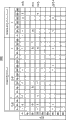
图6A示出色相直方图(即,彩色像素的直方图)的示例。图6B示出平均色相直方图的示例。平均色相直方图表示利用色相直方图所分类的像素的平均亮度、平均饱和度和平均色相。图7A示出亮度直方图(即,非彩色像素的直方图)的示例。图7B示出平均亮度直方图的示例。平均亮度直方图表示利用亮度直方图所分类的像素的平均亮度。在色相直方图400中分类(登记)彩色像素。FIG. 6A shows an example of a hue histogram (ie, a histogram of color pixels). FIG. 6B shows an example of an average hue histogram. The average hue histogram represents the average brightness, average saturation, and average hue of pixels classified using the hue histogram. FIG. 7A shows an example of a brightness histogram (ie, a histogram of achromatic pixels). FIG. 7B shows an example of an average luminance histogram. The average luminance histogram represents the average luminance of pixels classified using the luminance histogram. Color pixels are classified (registered) in the
系统控制器107针对存在于追踪对象区域302内部的各色相(图6A中的“色相”),计数存在于该追踪对象区域内部(图6A中的“内部”)的像素数和存在于该追踪对象区域外部(图6A中的“外部”)的像素数。The
在图6A和6B所示的示例中,系统控制器107以每40°角的分割单位(分类单位)生成色相直方图400。然而,如果分割单位根据期望的追踪精度而改变,也是有用的。在亮度直方图440中分类(登记)非彩色像素。In the example shown in FIGS. 6A and 6B , the
系统控制器107针对存在于追踪对象区域302内部的各亮度Y,计数存在于该追踪对象区域内部(“内部”)的像素数和存在于该追踪对象区域外部(“外部”)的像素数。在图7A和7B所示的示例中,系统控制器107以40LSB为分割单位生成亮度直方图440。然而,分割单位可以根据期望的追踪精度而改变。The
在生成色相直方图400和亮度直方图440之后,系统控制器107计算追踪对象区域内部和外部的各色相的存在比率。可以通过以下表达式来计算追踪对象区域内部和外部的各色相的存在比率:After generating the
追踪对象区域内部和外部的各色相的存在比率[%]=存在于追踪对象区域内部的像素数/存在于追踪对象区域外部的像素数。Existence ratio [%] of each hue inside and outside the tracking target area=the number of pixels existing inside the tracking target area/the number of pixels existing outside the tracking target area.
例如,在图6A所示的示例中,存在15个具有粉色色相的像素,即追踪对象区域302内部的2个具有粉色色相的像素和追踪对象区域302外部的13个具有粉色色相的像素。因此,其存在比率为15%(=(2/13)×100)。For example, in the example shown in FIG. 6A , there are 15 pixels with a pink hue, namely, 2 pixels with a pink hue inside the tracking
然而,如果追踪对象区域内存在一个或多个像素并且如果存在于追踪对象区域外部的像素数为0,则存在比率为100%。以上述方式计算存在比率。然而,本发明不局限于此。更具体地,如果通过以下表达式计算存在比率,也是有用的:However, if one or more pixels exist within the tracking target area and if the number of pixels existing outside the tracking target area is 0, the presence ratio is 100%. The presence ratio was calculated in the above-mentioned manner. However, the present invention is not limited thereto. More specifically, it is also useful if the presence ratio is calculated by the following expression:
存在比率[%]=[存在于追踪对象区域内部的像素数/(存在于追踪对象区域内部的像素数+存在于追踪对象区域外部的像素数)]×100。Existence ratio [%]=[number of pixels existing inside the tracking target area/(number of pixels existing inside the tracking target area+number of pixels existing outside the tracking target area)]×100.
除了计算色相的分布以外,系统控制器107还按存在于追踪对象区域302内部的像素的直方图的分割单位,计算以该分割单位所分类的像素的平均亮度AveY、平均饱和度AveChroma和平均色相AveHue。In addition to calculating the hue distribution, the
更具体地,在图6A所示的色相直方图400中,追踪对象区域302内部存在3个具有黄色色相的像素。因此,在图6B所示的平均色相直方图420中,这3个像素的平均亮度AveY为153LSB,平均饱和度AveChroma为55LSB,并且平均色相AveHue为113°。More specifically, in the
类似地,在图7A所示的直方图440中,追踪对象区域302内部存在3个具有非彩色色相(白色色相)的像素。因此,在图7B所示的平均亮度直方图480中,这3个像素的平均亮度为210LSB。Similarly, in the
如上所述,作为与存在于追踪对象区域302内部的彩色像素有关的信息,获取色相直方图400以及按色相直方图400所分类的平均亮度AveY、平均饱和度AveChroma和平均色相AveHue(平均色相直方图420)。另外,作为与存在于追踪对象区域302内部的非彩色像素有关的信息,获取亮度直方图440以及按亮度直方图440所分类的平均亮度AveY(平均亮度直方图480)。在以下说明中,如果需要,则将色相直方图400、平均色相直方图420、亮度直方图440和平均亮度直方图480统称为“主直方图”。As described above, the
返回图4,在步骤S202中,系统控制器107生成与按主直方图的色相直方图400和亮度直方图440各自的分割单位所分类的各像素邻接的像素集合的直方图500和520。在以下说明中,如果需要,则将直方图500和520统称为“邻接直方图”。Returning to FIG. 4 , in step S202 , the
图8A~8D和图9A~9D示意性示出要生成邻接直方图的像素的第一示例和第二示例。如图6A和6B以及图7A和7B所示,假定已经获取到8个分布,其中这8个分布包括:粉色、黄色、绿色和蓝色2这4个分布,即与追踪对象区域302内部的彩色像素有关的信息;以及黑色0、黑色1、灰色2和白色这4个分布,即与追踪对象区域302内部的非彩色像素有关的信息。图8A~8D以及图9A~9D示出具有这8个分布的各像素的邻接像素的示例。8A to 8D and FIGS. 9A to 9D schematically show a first example and a second example of pixels for which the adjacency histogram is to be generated. As shown in FIGS. 6A and 6B and FIGS. 7A and 7B , it is assumed that 8 distributions have been obtained, and these 8 distributions include: pink, yellow, green and blue 2 distributions, which are related to the inside of the tracking
参考图8A,由围绕2个粉色像素550和552的圆来表示与这2个粉色像素邻接的像素。在粉色像素550周围分布有包括1个蓝色2像素、1个灰色2像素、1个黑色1像素、2个粉色像素、1个白色像素和2个绿色像素总共8个像素。另外,在粉色像素552周围分布有包括1个灰色2像素、3个黑色1像素、1个黑色0像素、1个白色像素、1个绿色像素和1个粉色像素总共8个像素。Referring to FIG. 8A , the pixels adjacent to the two
系统控制器107基于围绕粉色像素550和552的16个像素来生成直方图,其中这16个像素构成与粉色像素550和552邻接的像素集合。The
类似地,在图8B所示的示例中,总共存在24个像素与3个黄色像素554、556和558邻接。在图8C所示的示例中,总共存在16个像素与2个绿色像素560和562邻接。在图8D所示的示例中,总共存在8个像素与1个蓝色2像素564邻接。Similarly, in the example shown in FIG. 8B , there are a total of 24 pixels adjacent to the 3
图9A~9D示出与非彩色像素邻接的像素的示例。更具体地,在图9A~9D中示出黑色0像素、黑色1像素、灰色2像素和白色像素的邻接像素。9A to 9D show examples of pixels adjacent to achromatic pixels. More specifically, adjacent pixels of a black 0 pixel, a black 1 pixel, a gray 2 pixel, and a white pixel are shown in FIGS. 9A to 9D .
在本实施例中,对于图5所示的追踪对象区域304用的主直方图,系统控制器107生成存在于追踪对象区域304内部的像素的直方图。另一方面,对于邻接像素,系统控制器107执行存在于比追踪对象区域304宽的区域中的邻接像素的识别。In this embodiment, the
利用上述结构,根据本实施例的系统控制器107可以获取与邻接像素有关的信息,其中,该信息包括与追踪对象物体和其背景之间的关系有关的信息。因此,本实施例能够获取适当的追踪结果。然而,如果对于两者参考相同的区域,也是有用的。With the above structure, the
系统控制器107将包括图8A~8D和图9A~9D所示的与按主直方图的各分割单位所分类的各像素相邻接的像素的像素集合的直方图(邻接直方图)与主直方图相关联。此外,系统控制器107按图10和11所示的格式存储邻接直方图和主直方图。The
图10示出与主直方图的色相直方图相对应的邻接直方图的示例。图11示出与主直方图的亮度直方图相对应的邻接直方图的示例。FIG. 10 shows an example of an adjacency histogram corresponding to the hue histogram of the main histogram. FIG. 11 shows an example of a contiguous histogram corresponding to the luminance histogram of the main histogram.
在邻接直方图中,作为与邻接像素的分布有关的信息,系统控制器107可以从彩色(“Color”)像素提取亮度(“Y”)、饱和度(saturation)(“色度(Chroma)”)和色相(“Hue”),并且可以获取它们各自的分布。此外,系统控制器107可以基于非彩色(“Colorless”)像素获取亮度Y的分布。In the adjacency histogram, as information about the distribution of adjacent pixels, the
在本实施例中,通过执行步骤S201和S202中的处理,实现了存储单元。更具体地,通过执行步骤S201中的处理实现了主直方图存储单元的示例,而通过执行步骤S202中的处理实现了邻接直方图存储单元的示例。In this embodiment, by performing the processing in steps S201 and S202, a storage unit is realized. More specifically, an example of a main histogram storage unit is realized by executing the processing in step S201, and an example of an adjacency histogram storage unit is realized by executing the processing in step S202.
在本实施例中,如果要评价的像素是彩色像素,则该像素的第一属性是色相(“Hue”)。另一方面,如果要评价的像素是非彩色像素,则该像素的第一属性是亮度(“Y”)。In this embodiment, if the pixel to be evaluated is a color pixel, the first attribute of the pixel is hue ("Hue"). On the other hand, if the pixel to be evaluated is an achromatic pixel, the first attribute of the pixel is brightness ("Y").
在本实施例中,如果要评价的像素的邻接像素是彩色像素,则该邻接像素的第二属性包括色相(“Hue”)、饱和度(“色度”)和亮度(“Y”)。另一方面,如果要评价的像素的邻接像素是非彩色像素,则该邻接像素的第二属性是亮度(“Y”)。In this embodiment, if the adjacent pixels of the pixel to be evaluated are color pixels, the second attributes of the adjacent pixels include hue ("Hue"), saturation ("chroma") and lightness ("Y"). On the other hand, if the neighbor of the pixel to be evaluated is an achromatic pixel, the second attribute of the neighbor is brightness ("Y").
在图4的流程图所示的包括获取主直方图和邻接直方图的追踪对象物体识别处理结束之后,在步骤S103(图3),系统控制器107执行用于判断是否可以对追踪对象物体进行追踪的处理。After the tracking target object recognition process including acquiring the main histogram and the adjacent histogram shown in the flow chart of FIG. Tracking Processing.
图12A和12B是示出图3所示的流程图中的步骤S103中的可追踪性判断处理的示例的流程图。12A and 12B are flowcharts illustrating an example of traceability determination processing in step S103 in the flowchart illustrated in FIG. 3 .
参考图12A和12B,在步骤S301和S302中,系统控制器107按以上参考图4、图6A和6B以及图7A和7B所述的方式,针对存在于追踪对象区域内部或外部的像素生成包括色相直方图和亮度直方图的主直方图。12A and 12B, in steps S301 and S302, the
在图12A和12B所示的流程图中,“aHistColorTarget[m]”表示图6A所示的色相直方图400中的各色相(“Hue”)的存在于追踪对象区域内部(“内部”)的像素数。另外,“aHistYTarget[n]”表示图7A所示的亮度直方图440中的各亮度Y的存在于追踪对象区域内部(“内部”)的像素数。此外,“aHistColorOther[m]”表示图6A所示的色相直方图400中的各色相(“Hue”)的存在于追踪对象区域外部(“外部”)的像素数。此外,“aHistYOther[n]”表示图7A所示的亮度直方图440中的各亮度Y的存在于追踪对象区域外部(“外部”)的像素数。另外,系统控制器107基于上述值,生成图6B所示的平均色相直方图和图7B所示的平均亮度直方图。In the flowcharts shown in FIGS. 12A and 12B , "aHistColorTarget[m]" indicates the color of each hue ("Hue") in the
在步骤S303中,系统控制器107判断按色相直方图中所包括的分割单位像素是否分布在追踪对象区域内部。在本实施例中,步骤S303中使用的“aHistColorTarget[i]”表示与色相直方图400中的特定色相(“Hue”)(i)相对应的存在于追踪对象区域内部(“内部”)的像素数的值。更具体地,在步骤S303中,系统控制器107判断aHistColorTarget[i]是否大于0。In step S303 , the
如果在追踪对象区域内部存在具有色相(i)的一个或多个像素(步骤S303中为“是”),则处理进入步骤S304。在步骤S304中,系统控制器107针对色相(“Hue”)(i)计算追踪对象区域内部或外部的存在比率。If there are one or more pixels having hue (i) inside the tracking target area (YES in step S303 ), the process advances to step S304 . In step S304 , the
如以上参考图6A和7A所述,计算追踪对象区域内部或外部的色相的存在比率。更具体地,系统控制器107通过将针对色相(“Hue”)(i)的存在于追踪对象区域内部(“内部”)的像素数(aHistColorTarget[i])除以存在于追踪对象区域外部(“外部”)的像素数(aHistColorOther[i])获得的结果乘以100,来计算该存在比率。然而,如果aHistColorTarget[i]≥1并且如果aHistColorOther[i]=0,则存在比率为100%。As described above with reference to FIGS. 6A and 7A , the abundance ratio of the hue inside or outside the tracking target area is calculated. More specifically, the
在步骤S305中,系统控制器107判断存在比率是否高于作为预定色相采用条件的比率。如果判断为存在比率不高于作为预定色相采用条件的比率(步骤S305中为“否”),则判断为与追踪对象物体的颜色相同的颜色大量存在于背景中,并且如果执行使用该颜色的追踪,则追踪的精度可能较低。因此,在步骤S306中,为了实现高追踪精度,系统控制器107判断为不采用要处理的色相Hue(i)。In step S305, the
另一方面,如果判断为存在比率高于作为预定色相采用条件的比率,则处理进入步骤S307。在步骤S307中,系统控制器107判断为将采用要处理的色相Hue(i)。On the other hand, if it is determined that the presence ratio is higher than the ratio that is the predetermined hue adoption condition, the process proceeds to step S307. In step S307, the
在步骤S308中,系统控制器107存储处理对象色相Hue(i)的“SumOKTarget”和“SumOKOther”。在本实施例中,“SumOKTarget”表示存在于追踪对象区域内部的像素数(“aHistColorTarget[i]”)的总数。此外,在本实施例中,“SumOKOther”表示存在于追踪对象区域外部的像素数(“aHistColorOther[i]”)的总数。在步骤S309中,系统控制器107针对所有的色相Hue(i)重复步骤S303~S308中的处理。In step S308, the
如上所述,在本实施例中,系统控制器107判断是否采用色相直方图的所有分割单位的色相Hue(i)。另外,系统控制器107存储所采用的像素数的总和。As described above, in the present embodiment, the
此外,系统控制器107针对亮度直方图判断追踪对象区域内部和外部的像素的存在比率是否高于作为预定亮度采用条件的比率。在步骤S310~S316中,系统控制器107判断是否采用亮度直方图的分割单位的亮度Y(i)。Further, the
表示存在于追踪对象区域内部的像素的总数的“SumOKTarget”以及表示存在于追踪对象区域外部的像素的总数的“SumOKOther”分别是将具有所采用的亮度Y(i)的像素数和具有所采用的色相Hue(i)的像素数的总和相加所计算出的值。"SumOKTarget" indicating the total number of pixels existing inside the tracking target area and "SumOKOther" indicating the total number of pixels existing outside the tracking target area are the number of pixels with the adopted luminance Y(i) and the number of pixels with the adopted luminance Y(i), respectively. The value calculated by adding the sum of the number of pixels of Hue(i) to Hue(i).
因此,由此产生的表示存在于追踪对象区域内部的像素的总数的“SumOKTarget”是具有所采用的色相Hue(i)的像素数的总和。此外,由此产生的表示存在于追踪对象区域外部的像素的总数的“SumOKOther”是具有所采用的亮度Y(i)的像素数的总和。Therefore, the resulting "SumOKTarget" representing the total number of pixels existing inside the tracking target area is the sum of the number of pixels having the adopted hue Hue(i). Also, the resulting "SumOKOther" indicating the total number of pixels existing outside the tracking target area is the sum of the number of pixels with the adopted luminance Y(i).
在本实施例中,可以彼此独立地设置“色相采用条件”和“亮度采用条件”。特别地,与彩色相比,不太容易使用非彩色作为追踪对象物体的特性。因此,对于非彩色,针对亮度采用条件可以设置比色相采用条件更严格的采用条件。In this embodiment, the "hue adoption condition" and the "brightness adoption condition" can be set independently of each other. In particular, it is less easy to use achromatic color as a characteristic of a tracking target object than color. Therefore, for an achromatic color, stricter adoption conditions can be set for the brightness adoption conditions than the hue adoption conditions.
另外,尽管图中未示出,然而代替设置彩色或非彩色的采用条件,如果仅针对特定颜色或亮度改变采用条件,也是有用的。另外,如果不执行步骤S303~S309中的处理或步骤S310~S316中的处理,也是有用的。In addition, although not shown in the figure, instead of setting the adoption condition of chromatic or achromatic, it is also useful if the adoption condition is changed only for a specific color or luminance. In addition, it is also useful if the processing in steps S303 to S309 or the processing in steps S310 to S316 is not performed.
在按色相直方图和亮度直方图(主直方图)中的分割单位执行上述采用判断处理之后,处理进入步骤S317。在步骤S317中,系统控制器107确定所采用的存在于追踪对象区域内部的彩色像素或非彩色像素的比率。After the above-described adoption determination processing is performed in units of divisions in the hue histogram and the brightness histogram (main histogram), the process proceeds to step S317. In step S317, the
更具体地,系统控制器107通过将作为所采用的存在于追踪对象区域内部的像素的总数的“SumOKTarget”除以存在于框内的像素数所计算出的值乘以100,来计算该比率。More specifically, the
在步骤S318中,系统控制器107判断该比率是否高于预定的框内条件。如果判断为该比率不高于预定的框内条件(步骤S318中为“否”),则处理进入步骤S319。在步骤S319中,系统控制器107判断为尚未获取到追踪对象物体的适当特性,并且不能追踪该追踪对象物体。In step S318, the
另一方面,如果判断为该比率高于框内条件(步骤S318中为“是”),则系统控制器107判断为已经获取到追踪对象物体的适当特性。然后,处理进入步骤S320。在步骤S320中,系统控制器107计算所采用的彩色像素或非彩色像素在画面内的存在比率。On the other hand, if it is determined that the ratio is higher than the in-frame condition (YES in step S318 ), the
更具体地,系统控制器107按以下方式计算该比率。首先,系统控制器107将作为存在于追踪对象区域内部的像素的总数的SumOKTarget与作为存在于追踪对象区域外部的像素的总数的SumOKOther相加。然后,系统控制器107将相加结果除以存在于画面内的像素数。然后,系统控制器107将相除结果乘以100。More specifically, the
在步骤S321中,系统控制器107判断按上述方式计算出的比率是否低于预定的整个画面条件B。如果判断为该比率不低于预定的整个画面条件B(步骤S321中为“否”),则处理进入步骤S319。在步骤S319中,系统控制器107判断为:由于因大量要追踪的彩色像素或非彩色像素存在于位于追踪对象区域外部的背景区域中而可能导致追踪性能下降,因此不能追踪该追踪对象物体。In step S321, the
另一方面,如果判断为该比率低于预定的整个画面条件B(步骤S321中为“是”),则处理进入步骤S322。在步骤S322中,系统控制器107判断为可以追踪该追踪对象物体。On the other hand, if it is determined that the ratio is lower than the predetermined whole screen condition B (YES in step S321), the process proceeds to step S322. In step S322, the
如上所述,系统控制器107在包括与各颜色和亮度有关的单个属性评价处理、针对存在于追踪对象区域内部的像素的评价处理以及针对整个画面中所包括的像素的评价处理的多个阶段中,判断是否能够追踪该追踪对象物体。因此,根据本实施例的系统控制器107能够可靠且适当地判断是否能够对追踪对象物体进行追踪。然而,不总是需要执行步骤S320和S321中的整个画面评价。As described above, the
返回图3,在步骤S104中,系统控制器107基于以上所述的可追踪性判断处理的结果判断是否能够对追踪对象区域进行追踪。如果判断为不能对追踪对象区域进行追踪(步骤S104中为“否”),则根据图3的流程图的处理结束。另一方面,如果判断为能够对追踪对象区域进行追踪(步骤S104中为“是”),则开始追踪循环处理。Returning to FIG. 3 , in step S104 , the
在该追踪循环处理中,在步骤S105中,系统控制器107判断是否可以进行继续追踪。图13是示出图3所示的流程图中的步骤S105中的继续追踪可行性判断处理的示例的流程图。In this tracking loop process, in step S105, the
参考图13,在步骤S401中,系统控制器107计算存在于画面内的图6A和7A所示的直方图所采用的彩色像素和非彩色像素的比率。更具体地,系统控制器107通过将作为图6A和7A所示的直方图中采用的彩色像素和非彩色像素的总数的“SumOKALL”除以整个画面中所包括的像素数所计算出的值乘以100,来计算该比率。在本实施例中,像素的总数“SumOKALL”是通过将作为存在于追踪对象区域内部的像素的总数的“SumOKTarget”与作为存在于追踪对象区域外部的像素的总数的“SumOKOther”相加所计算出的值。Referring to FIG. 13 , in step S401 , the
在步骤S402中,系统控制器107判断该比率是否低于预定的整个画面条件C。如果判断为该比率不低于预定的整个画面条件C(步骤S402中为“否”),则处理进入步骤S403。在步骤S403中,系统控制器107判断为:由于因大量要追踪的彩色像素或非彩色像素存在于位于追踪对象区域外部的背景区域中而可能导致追踪性能下降,因此不能对追踪对象物体进行追踪。In step S402, the
另一方面,如果判断为该比率低于预定的整个画面条件C(步骤S402中为“是”),则处理进入步骤S404。在步骤S404中,系统控制器107判断为能够对追踪对象物体进行追踪。在本实施例中,可以将“整个画面条件C”设置为与“整个画面条件B”不同的条件,其中该整个画面条件B是作为以上参考图12B所述的步骤S321中的处理的用于判断是否能够对追踪对象物体进行追踪的最终判断条件。On the other hand, if it is determined that the ratio is lower than the predetermined entire screen condition C (YES in step S402), the process proceeds to step S404. In step S404, the
通过使用比整个画面条件B更严格的整个画面条件C,根据本实施例的系统控制器107能够在追踪开始之后背景的状况发生改变,由此具有与追踪对象物体的色相或亮度相同的色相或亮度的像素数增加时,判断是否立即暂停追踪。By using the overall screen condition C that is stricter than the overall screen condition B, the
在图13所示的示例中,将条件固定为整个画面条件C。然而,如果条件根据追踪开始之后所经过的时间而逐渐改变(变严),也是有用的。In the example shown in FIG. 13 , the condition is fixed to the entire screen condition C. However, it is also useful if the conditions are gradually changed (tightened) according to the elapsed time since the trace was started.
另外,如果针对仅基于色相追踪物体、仅基于亮度追踪物体以及基于色相和亮度这两者追踪物体的各种情况,使步骤S318中使用的“框内条件”(图12B)、步骤S321中使用的“整个画面条件B”(图12B)和步骤S402中使用的“整个画面条件C”(图13)变严,也是有用的。另外,如果进一步改变仅针对特定颜色的条件和仅针对特定亮度的条件,也是有用的。In addition, for the various situations of tracking objects based on hue only, tracking objects based on brightness only, and tracking objects based on both hue and brightness, the "inside condition" (FIG. 12B) used in step S318, It is also useful to make the "whole screen condition B" (FIG. 12B) and the "whole screen condition C" (FIG. 13) used in step S402 stricter. In addition, it is also useful if the condition for only a specific color and the condition for a specific brightness are further changed.
返回图3,在步骤S106中,系统控制器107基于继续追踪可行性判断处理的结果,判断是否能够继续对追踪对象区域进行追踪。如果判断为不能继续对追踪对象区域进行追踪(步骤S106中为“否”),则图3的流程图所示的处理结束。另一方面,如果判断为能够继续对追踪对象区域进行追踪(步骤S106中为“是”),则处理进入步骤S107。在步骤S107中,系统控制器107执行追踪对象物体检测处理。Returning to FIG. 3 , in step S106 , the
图14是示出图3所示的流程图中的步骤S107中的追踪对象物体检测处理的示例的流程图。可以在整个画面上或仅在该画面内的任意区域上执行追踪对象物体检测处理。然而,在本实施例中,假定在整个画面上执行追踪对象物体检测处理。FIG. 14 is a flowchart showing an example of tracking target object detection processing in step S107 in the flowchart shown in FIG. 3 . The tracking target object detection processing can be performed on the entire screen or only on an arbitrary area within the screen. However, in the present embodiment, it is assumed that tracking target object detection processing is performed on the entire screen.
图15示意性示出用于通过执行追踪对象物体检测处理来对追踪对象区域进行追踪的方法的示例。在画面内对追踪对象物体进行追踪时可以设置各种起点、方向或顺序。然而,在本实施例中,假定如图15所示,从画面的左上部分开始水平地执行追踪对象物体的追踪。然后,对下面的行顺次执行追踪。FIG. 15 schematically shows an example of a method for tracking a tracking target area by performing tracking target object detection processing. Various start points, directions, and sequences can be set when tracking objects to be tracked within the screen. However, in the present embodiment, it is assumed that the tracking of the tracking target object is performed horizontally from the upper left portion of the screen as shown in FIG. 15 . Then, trace is executed sequentially for the following lines.
参考图14,在步骤S501中,系统控制器107判断要处理的像素(要评价的像素)与分布在直方图中的像素是否匹配。更具体地,在步骤S501中,系统控制器107判断要处理的像素是否是作为存在于追踪对象区域内部的像素的、图6A和7A所示的主直方图中所存储的彩色像素或非彩色像素。另外,在步骤S501中,系统控制器107判断要处理的像素是否具有已存储在图6B和7B所示的平均直方图中的、落入该平均直方图的预定范围内的平均亮度、平均饱和度或平均色相。Referring to FIG. 14, in step S501, the
如果判断为要处理的像素与分布在主直方图中的像素不匹配(步骤S501中为“否”),则处理进入步骤S506。另一方面,如果判断为要处理的像素与分布在主直方图中的像素匹配(步骤S501中为“是”),则处理进入步骤S502。在步骤S502中,系统控制器107对该像素的位置分配额定点数(rating point)。If it is determined that the pixel to be processed does not match the pixels distributed in the main histogram (NO in step S501), the process advances to step S506. On the other hand, if it is determined that the pixel to be processed matches the pixels distributed in the main histogram (YES in step S501), the process advances to step S502. In step S502, the
图16A~16D示意性示出用于对要搜索的像素分配额定点数以检测追踪对象物体的方法的示例。参考图16A,如果要处理的像素(处理对象像素)650与主直方图中的彩色匹配,则系统控制器107对处理对象像素650分配1个额定点数。16A to 16D schematically show an example of a method for assigning a rated point to a pixel to be searched for detecting a tracking target object. Referring to FIG. 16A , if a pixel to be processed (pixel to be processed) 650 matches a color in the main histogram, the
另一方面,如图16B所示,如果处理对象像素660与主直方图中的非彩色匹配,则系统控制器107对处理对象像素660分配0个点数(不对处理对象像素660分配额定点数)。On the other hand, as shown in FIG. 16B , if the pixel to be processed 660 matches an achromatic color in the main histogram, the
可选地,采用以下结构也是有用的。更具体地,在这种情况下,如果处理对象像素650与主直方图中的彩色匹配,则系统控制器107对处理对象像素650分配2个额定点数。另一方面,在这种情况下,如果处理对象像素650与主直方图中的非彩色匹配,则系统控制器107分配1个点数,该点数是比在彩色的情况下分配的额定点数小的额定点数。Alternatively, it is also useful to adopt the following structure. More specifically, in this case, if the pixel to be processed 650 matches the color in the main histogram, the
在步骤S503中,系统控制器107判断处理对象像素的邻接像素与分布在邻接直方图中的像素是否匹配。更具体地,对于与主直方图匹配的像素,系统控制器107判断存在于处理对象像素610周围的8个像素与图10和11所示的邻接直方图是否匹配。In step S503 , the
如果判断为处理对象像素的邻接像素与分布在邻接直方图中的像素不匹配(步骤S503中为“否”),则处理进入步骤S505。另一方面,如果判断为处理对象像素的邻接像素与分布在邻接直方图中的像素匹配(步骤S503中为“是”),则处理进入步骤S504。在步骤S504中,系统控制器107对该像素的位置分配额定点数。If it is determined that the adjacent pixels of the processing target pixel do not match the pixels distributed in the adjacent histogram ("No" in step S503), the process proceeds to step S505. On the other hand, if it is determined that the adjacent pixels of the pixel to be processed match the pixels distributed in the adjacent histogram (YES in step S503 ), the processing proceeds to step S504 . In step S504, the
更具体地,如图16C所示,如果分布在邻接直方图中且具有与同主直方图中的彩色相匹配的彩色像素的色相不同的色相的彩色像素652与该同主直方图中的彩色相匹配的彩色像素相邻接,则系统控制器107分配5个点数。More specifically, as shown in FIG. 16C , if the
另一方面,如图16C所示,如果分布在邻接直方图中且具有与同主直方图中的彩色相匹配的彩色像素的色相相同的色相的彩色像素654与该同主直方图中的彩色相匹配的彩色像素相邻接,则系统控制器107分配4个点数。On the other hand, as shown in FIG. 16C , if the
此外,如图16C所示,如果分布在邻接直方图中的非彩色像素656与同主直方图中的彩色相匹配的彩色像素相邻接,则系统控制器107分配3个点数。Furthermore, as shown in FIG. 16C, if the
另一方面,如图16D所示,如果分布在邻接直方图中的彩色像素662与同主直方图中的非彩色相匹配的非彩色像素相邻接,则系统控制器107分配3个点数。On the other hand, as shown in FIG. 16D, if the
此外,如图16D所示,如果具有与同主直方图中的非彩色相匹配的非彩色像素的亮度不同的亮度的非彩色像素664与该同主直方图中的非彩色相匹配的非彩色像素相邻接,则系统控制器107分配2个点数。另一方面,如图16D所示,如果具有与同主直方图中的非彩色相匹配的非彩色像素的亮度相同的亮度的非彩色像素666与该同主直方图中的非彩色相匹配的非彩色像素相邻接,则系统控制器107分配2个点数。Furthermore, as shown in FIG. 16D, if an
在判断处理对象像素的邻接像素是否与分布在图10和11所示的邻接直方图中的任一像素相匹配时,如果该邻接像素是彩色像素,则如果仅基于色相来执行判断,也是有用的。可选地,在这种情况下,如果基于所有的色相、饱和度(“色度”)和亮度Y来执行判断,也是有用的。When judging whether an adjacent pixel of a pixel to be processed matches any of the pixels distributed in the adjacent histograms shown in FIGS. 10 and 11, if the adjacent pixel is a color pixel, it is also useful if the judgment is performed based on hue of. Optionally, in this case, it is also useful if the judgment is performed based on all hue, saturation ("chroma") and lightness Y.
在图16A~16D所示的例子中,要分配的额定点数根据处理对象像素和与该处理对象像素邻接的像素的组合而改变。然而,如果在上述所有情况下分配相同的额定点数,也是有用的。此外,如果分配与上述额定点数不同的额定点数,也是有用的。In the examples shown in FIGS. 16A to 16D , the number of rated points to be allocated changes depending on the combination of the pixel to be processed and the pixel adjacent to the pixel to be processed. However, it is also useful if the same rating points are assigned in all the above cases. In addition, it is also useful if rated points different from the above-mentioned rated points are assigned.
在追踪对象物体检测处理中,系统控制器107判断处理对象像素是否与分布在主直方图中的任一像素相匹配、以及与处理对象像素邻接的像素是否与分布在邻接直方图中的任一像素相匹配。In the tracking target object detection process, the
在上述判断中,系统控制器107不使用与主直方图和邻接直方图中所包括的像素数有关的信息。因此,可以从主直方图和邻接直方图中删除与像素数有关的信息。更具体地,在追踪对象物体检测处理中,需要如下信息:与追踪对象区域中所包括的各像素具有的属性有关的信息以及与追踪对象区域中所包括的各像素的各邻接像素具有的属性有关的信息。In the above judgment, the
换句话说,在追踪对象物体检测处理中,需要如下信息:与追踪对象区域中所包括的像素具有的属性有关的信息以及与追踪对象区域中所包括的各像素的邻接像素具有的属性有关的信息。In other words, in the tracking target object detection processing, information about attributes possessed by pixels included in the tracking target area and information about attributes possessed by pixels adjacent to each pixel included in the tracking target area are required. information.
如果追踪对象物体检测处理中所使用的分类数据可以包括上述信息,则该分类数据不局限于图6A和6B以及图7A和7B所示的主直方图。另外,如果使用具有与以上所述的格式不同的格式的主分类数据,也是有用的。If the classification data used in the tracking target object detection process can include the above information, the classification data is not limited to the main histogram shown in FIGS. 6A and 6B and FIGS. 7A and 7B . In addition, it is also useful if master taxonomy data with a format different from that described above is used.
另外,邻接分类数据不局限于图10和11所示的邻接直方图。更具体地,如果使用具有与以上所述的格式不同的格式的邻接分类数据,也是有用的。更具体地,代替生成并使用图6A和6B以及图7A和7B所示的主直方图,如果生成并使用仅表示存在于追踪对象区域内部的像素所具有的色相的类型的主分类数据,也是有用的。In addition, the adjacency classification data is not limited to the adjacency histogram shown in FIGS. 10 and 11 . More specifically, it is also useful if contiguous classification data with a format different from that described above is used. More specifically, instead of generating and using the main histograms shown in FIGS. 6A and 6B and FIGS. 7A and 7B , if main classification data indicating only the type of hue possessed by pixels existing inside the tracking target region is generated and used, it is also useful.
此外,代替生成并使用图10或11所示的邻接直方图,如果系统控制器107生成并使用仅表示存在于追踪对象区域内部的像素所具有的色相的类型以及邻接于该像素的所有像素各自所具有的色相的类型的邻接分类数据,也是有用的。Furthermore, instead of generating and using the adjacency histogram shown in FIG. Adjacency categorical data with the type of hue is also useful.
如以上参考图15以及图16A~16D所述,在本实施例中,系统控制器107评价存在于画面内的要处理的像素和与该像素邻接的像素之间的关系。另外,系统控制器107判断处理对象像素和主直方图之间的匹配状况以及邻接像素和邻接直方图之间的匹配状况。如果判断为它们彼此相匹配,则系统控制器107对所评价的像素的位置分配额定点数。在步骤S505中,系统控制器107判断是否已对所有的邻接像素完全执行了上述处理。As described above with reference to FIG. 15 and FIGS. 16A to 16D , in the present embodiment, the
如果判断为已对所有的邻接像素完全执行了上述处理(步骤S505中为“是”),则处理进入步骤S506。在步骤S506中,系统控制器107通过使用所分配的额定点数以及主直方图的各分割单位的平均亮度、平均饱和度和平均色相,对所评价的像素的各位置计算评价值,其中已按以上参考图6B和7B所述的方式存储了平均亮度、平均饱和度和平均色相。If it is determined that the above-described processing has been completely performed on all adjacent pixels (YES in step S505), the processing proceeds to step S506. In step S506, the
更具体地,如果所评价的像素为彩色像素,则系统控制器107使用以下表达式(1)来计算评价值,而如果所评价的像素是非彩色像素,则系统控制器107使用以下表达式(2)来计算评价值:More specifically, if the evaluated pixel is a color pixel, the
其中,“ΔHue”表示所评价的像素的色相与已存储在图6B和7B所示的平均直方图中的平均色相之间的差,“ΔChroma”表示所评价的像素的饱和度与先前存储在图6B和7B所示的平均直方图中的平均饱和度之间的差,“ΔY”表示所评价的像素的亮度与先前存储在图6B和7B所示的平均直方图中的平均亮度之间的差,并且“ΔDistance”表示如下框的位置与所评价的像素的位置之间的距离,其中该框表示由显示装置105所显示的追踪对象物体的位置。如果检测追踪对象物体的精度极高,则距离“ΔDistance”是不必要的,或者“ΔDistance”可以非常小。where "ΔHue" represents the difference between the hue of the evaluated pixel and the average hue already stored in the average histogram shown in Figures 6B and 7B, and "ΔChroma" represents the difference between the saturation of the evaluated pixel and the value previously stored in The difference between the average saturation in the average histograms shown in Figures 6B and 7B, "ΔY" represents the difference between the brightness of the pixel being evaluated and the average brightness previously stored in the average histograms shown in Figures 6B and 7B , and “ΔDistance” represents the distance between the position of the frame representing the position of the tracking target object displayed by the
然而,如果所评价的像素周围存在大量具有类似色相或亮度的像素,则可以通过将特定距离系数添加至表达式(1)和(2)的项来抑制由于检测追踪对象物体的低精度而可能发生的框的显示的猎振(hunting)现象。However, if there are a large number of pixels with similar hue or brightness around the evaluated pixel, it is possible to suppress possible loss due to low accuracy in detecting the tracking target object by adding a certain distance coefficient to the terms of Expressions (1) and (2). The hunting phenomenon of the displayed frame occurs.
在表达式(1)和(2)中,将不同的单位系的项彼此相加。因此,为了保持它们之间的平衡,使用系数“K0”~“K4”。可选地,为了简化处理,如果使用常数作为表达式(1)和(2)各自的分母,也是有用的。这是因为:如果步骤S501中的判断的标准被设置得严格,则表达式(1)和(2)各自的分母中的“ΔHue”和“ΔChroma”的值的变化范围变小。In expressions (1) and (2), terms of different unit systems are added to each other. Therefore, in order to maintain a balance between them, coefficients "K0" to "K4" are used. Alternatively, in order to simplify the processing, it is also useful if constants are used as the denominators of the expressions (1) and (2) respectively. This is because if the criterion of the judgment in step S501 is set strictly, the variation range of the values of "ΔHue" and "ΔChroma" in the denominators of the respective expressions (1) and (2) becomes small.
在步骤S507中,系统控制器107判断是否已经完成对存在于画面内的所有像素的评价值的计算。如果判断为尚未完成对存在于画面内的所有像素的评价值的计算(步骤S507中为“否”),则处理返回至步骤S501。另一方面,如果判断为已经完成对存在于画面内的所有像素的评价值的计算(步骤S507中为“是”),则处理进入步骤S508。In step S507, the
在步骤S508中,系统控制器107使用计算出的评价值来识别追踪对象物体的位置。更具体地,如果系统控制器107搜索计算出的评价值达到其以像素为单位的峰值的位置,并将该位置设置为追踪对象物体的位置,也是有用的。另外,如果系统控制器107搜索具有比预定值高的评价值的像素的集合的位置,并将这些像素的集合的位置设置为追踪对象物体的位置,也是有用的。In step S508, the
然而,如果不能确定出该评价值达到特定值的位置,即如果通过使用计算出的评价值不能识别出追踪对象物体的位置,则系统控制器107不识别追踪对象物体的位置。However, if the position at which the evaluation value reaches a certain value cannot be determined, that is, if the position of the tracking target object cannot be identified by using the calculated evaluation value, the
如果已经识别出追踪对象物体的位置,则系统控制器107根据识别出的追踪对象物体的位置来确定用于显示框的位置。如果尚未识别出追踪对象物体的位置,则系统控制器107不确定用于显示框的位置。If the position of the tracking target object has been recognized, the
在本实施例中,通过执行以上所述的步骤S502、S504和S506中的处理,实现了分配单元的示例。另外,在本实施例中,通过执行步骤S508和S509中的处理,实现了改变单元的示例。In this embodiment, an example of an allocation unit is realized by executing the processing in steps S502, S504, and S506 described above. In addition, in the present embodiment, by executing the processing in steps S508 and S509, an example of a changing unit is realized.
图17示出评价值的计算结果的示例。在图17所示的示例中,示出了在图像已从图2A所示的图像变为图2B所示的图像的情况下图2B所示的图像的评价值。FIG. 17 shows an example of calculation results of evaluation values. In the example shown in FIG. 17 , evaluation values of the image shown in FIG. 2B in a case where the image has changed from the image shown in FIG. 2A to the image shown in FIG. 2B are shown.
在图17所示的示例中,纵轴和横轴分别表示图2B所示的图像在垂直方向上的坐标和该图像在水平方向上的坐标。垂直于与这两轴平行的平面的另一轴表示各坐标处的评价值。In the example shown in FIG. 17 , the vertical axis and the horizontal axis represent the coordinates of the image shown in FIG. 2B in the vertical direction and the coordinates of the image in the horizontal direction, respectively. The other axis perpendicular to the plane parallel to these two axes represents the evaluation value at each coordinate.
在图2A所示的例子中,示出了确定追踪对象物体时的图像。系统控制器107将区域202内的部分识别为追踪对象区域。另外,系统控制器107生成该追踪对象区域的主直方图和邻接直方图。In the example shown in FIG. 2A , an image when the tracking target object is specified is shown. The
在图2B所示的示例中,示出了追踪对象区域已经移动之后的图像。在该状态下计算出的评价值具有图17所示的分布。结果,系统控制器107可以在具有高评价值612的区域中显示表示追踪对象区域的框。In the example shown in FIG. 2B , an image after the tracking target area has moved is shown. The evaluation values calculated in this state have the distribution shown in FIG. 17 . As a result, the
在本实施例中,在图17所示的示例中,存在具有不同于评价值612的高评价值620、622和624的多个区域。In the present embodiment, in the example shown in FIG. 17 , there are a plurality of regions having
假定表示当前所显示的追踪对象区域的框存在于具有评价值620的位置处。评价值620低于评价值612。此外,具有评价值620的像素的位置离具有评价值612的像素较近。因此,可能已将框显示在该追踪对象物体上。Assume that a frame representing a currently displayed tracking target area exists at a position having an
因此,在这种情况下,如果系统控制器107不改变显示该框的位置,也是有用的。更具体地,代替将位置改变为评价值612的位置,如果将该框显示在评价值620的位置处,也是有用的。Therefore, in this case, it is also useful if the
返回图3,在步骤S108中,系统控制器107判断作为图14所示的步骤S508的处理结果,是否已经检测到追踪对象区域。如果判断为已经检测到追踪对象区域(步骤S108中为“是”),则处理进入步骤S109。在步骤S109中,系统控制器107在图14中的步骤S509中确定的框显示位置处显示框。然后,处理返回至步骤S105。Returning to FIG. 3 , in step S108 , the
另一方面,如果没有检测到追踪对象区域(步骤S108中为“否”),则处理进入步骤S110。在步骤S110中,系统控制器107判断是否已发生超时(即,自判断为没有检测到追踪对象区域的时刻起是否已经过预定时间)。On the other hand, if no tracking target area has been detected (NO in step S108), the process advances to step S110. In step S110, the
如果判断为已发生超时(步骤S110中为“是”),则结束图3的流程图所示的处理。另一方面,如果判断为没有发生超时(步骤S110中为“否”),则处理返回至步骤S105。If it is determined that a timeout has occurred (YES in step S110), the processing shown in the flowchart of FIG. 3 is ended. On the other hand, if it is determined that the timeout has not occurred (NO in step S110), the process returns to step S105.
如上所述,在本实施例中,系统控制器107生成作为对存在于追踪对象区域内部或外部的像素分类得到的主分类数据的直方图(主直方图)。更具体地,对于彩色,系统控制器107生成色相直方图400。对于非彩色,系统控制器107生成亮度直方图440。另外,对于存在于追踪对象区域内部的各像素,系统控制器107生成作为对与该像素邻接的像素分类得到的邻接分类数据的直方图500和520(邻接直方图)。As described above, in the present embodiment, the
在检测追踪对象物体时,如果主直方图中存在具有与处理对象像素的属性相对应的属性的像素,则系统控制器107增大该处理对象像素的评价值。另一方面,如果邻接直方图中存在具有与处理对象像素的邻接像素的属性相对应的属性的像素,则系统控制器107增大该处理对象像素的评价值。When detecting a tracking target object, if there is a pixel having an attribute corresponding to an attribute of a processing target pixel in the main histogram, the
对于邻接直方图,本实施例仅判断处理对象像素的邻接像素的属性,而没有判断邻接像素相对于处理对象像素的方位。因此,如果追踪对象物体的方位因转动而变化,或者如果追踪设备(摄像设备)自身在垂直方向或水平方向上的姿势已改变,则可能不容易影响评价值。For the adjacent histogram, this embodiment only judges the attributes of the adjacent pixels of the pixel to be processed, but does not judge the orientation of the adjacent pixels relative to the pixel to be processed. Therefore, if the orientation of the tracking target object changes due to rotation, or if the posture of the tracking device (imaging device) itself in the vertical or horizontal direction has changed, the evaluation value may not be easily affected.
通过使用邻接直方图,本实施例判断与各处理对象像素邻接的像素的属性。因此,即使追踪对象物体自身的形状已经变形,本实施例仍能够提高追踪性能。By using the adjacency histogram, the present embodiment judges the attributes of pixels adjacent to each pixel to be processed. Therefore, even if the shape of the tracking target object itself has been deformed, the present embodiment can still improve the tracking performance.
更具体地,如果已经将直视前方的人物的面部设置为追踪对象物体,并且如果该追踪对象物体(人物的面部)倾斜朝向侧方,则该人物的面部的图像的宽度减小。因此,在这种情况下,人物的面部的图像的形状可能不同于该人物的面部被设置为追踪对象物体时的形状。More specifically, if the face of a person looking straight ahead has been set as a tracking target object, and if the tracking target object (person's face) is tilted toward the side, the width of the image of the person's face is reduced. Therefore, in this case, the shape of the image of the person's face may be different from the shape when the person's face is set as the tracking target object.
另外,如果已经将直视前方的人物的面部设置为追踪对象物体,并且如果该人物靠近追踪设备,则人物的面部的图像的大小可能不同于该人物的面部被设置为追踪对象物体时的大小。Also, if the face of a person looking straight ahead has been set as the tracking target object, and if the person is close to the tracking device, the size of the image of the person's face may be different from the size when the person's face was set as the tracking target object .
例如,关注与人物的眼角相对应的像素、与眼睛的虹膜的外缘相对应的像素以及与唇角相对应的像素这三个像素。在该示例中,如果人物的面部的方位改变,或者如果人物的面部靠近追踪设备,则这三个像素之间的方向关系以及它们之间的相对距离发生改变。然而,在这种情况下,容易理解,各像素的属性以及与该像素邻接的像素的属性的变化量较小。For example, attention is paid to three pixels of a pixel corresponding to the corner of the eye of a person, a pixel corresponding to the outer edge of the iris of the eye, and a pixel corresponding to the corner of the lip. In this example, if the orientation of the person's face changes, or if the person's face approaches the tracking device, the directional relationship between these three pixels, as well as the relative distance between them, changes. However, in this case, it is easy to understand that the amount of change in the attributes of each pixel and the attributes of pixels adjacent to the pixel is small.
在本实施例中,系统控制器107对画面中所包括的所有像素执行上述评价值计算。此外,系统控制器107将包括具有高评价值的像素的区域设置为追踪对象区域。In the present embodiment, the
利用上述结构,在传统的追踪方法不能执行适当的追踪操作的状态下,本实施例能够提高追踪性能。With the above structure, the present embodiment can improve the tracking performance in a state where the conventional tracking method cannot perform an appropriate tracking operation.
另外,具有上述结构的本实施例无需存储追踪用的模板图像。因此,能够节省存储容量。此外,在图像分辨率低的情况下,本实施例能够提高追踪性能。因此,本实施例不需要高的图像处理性能。In addition, the present embodiment having the above-mentioned structure does not need to store a template image for tracking. Therefore, storage capacity can be saved. In addition, this embodiment can improve tracking performance in the case of low image resolution. Therefore, this embodiment does not require high image processing performance.
下面,将详细说明本发明第二实施例。在本实施例中,如果可以利用帧间差分法,则通过帧间差分法来对追踪对象物体进行追踪。另一方面,在本实施例中,如果不能利用帧间差分法进行追踪,则按与以上在第一实施例中所述的方式类似的方式来对追踪对象物体进行追踪。Next, a second embodiment of the present invention will be described in detail. In this embodiment, if the inter-frame difference method can be used, the tracking target object is tracked by the inter-frame difference method. On the other hand, in this embodiment, if the inter-frame difference method cannot be used for tracking, the tracking target object is tracked in a manner similar to that described above in the first embodiment.
换句话说,本实施例与上述第一实施例的不同点在于:本实施例使用帧间差分法。利用与以上参考图1~17所述的第一实施例的附图标记或符号相同的附图标记或符号来设置与第一实施例的组件相同的本实施例的组件。因此,这里将不重复对这些组件的说明。In other words, the difference between this embodiment and the first embodiment above is that this embodiment uses the inter-frame difference method. The same components of the present embodiment as those of the first embodiment are provided with the same reference numerals or symbols as those of the first embodiment described above with reference to FIGS. 1 to 17 . Therefore, descriptions of these components will not be repeated here.
图18是示出由根据本实施例的摄像设备所执行的用于对追踪对象物体进行追踪的处理的示例的主流程图。FIG. 18 is a main flowchart showing an example of processing for tracking a tracking target object executed by the imaging apparatus according to the present embodiment.
参考图18,在步骤S1001中,系统控制器107确定追踪对象物体的位置和大小。在步骤S1002中,系统控制器107执行追踪对象物体识别处理。在步骤S1003中,系统控制器107执行可追踪性判断处理。在步骤S1001~S1003中,系统控制器107执行与图3的流程图所示的步骤S101~S103中的处理相同的处理。Referring to FIG. 18, in step S1001, the
在步骤S1004中,系统控制器107通过使用帧间相对差分法对追踪对象区域进行追踪。在帧间相对差分法期间,系统控制器107使用存在于所指定的追踪位置处的图像数据作为模板图像,并从随后的图像帧中搜索要进行模式匹配的区域。In step S1004, the
另外,系统控制器107将存在于被检测为要进行模式匹配的区域的位置处的图像数据更新为模板图像。此外,系统控制器107继续从随后的帧图像中搜索要进行模式匹配的区域。In addition, the
如上所述,在本实施例中,系统控制器107在顺次更新模板图像的同时,继续从随后的帧图像对追踪对象物体进行追踪。当使用帧间相对差分法时,不能执行模式匹配,并且在一些情况下判断为不能对追踪对象物体进行追踪。As described above, in this embodiment, the
因此,在步骤S1005中,系统控制器107判断是否能够利用帧间相对差分法进行追踪。更具体地,如果追踪对象物体的方位由于其转动已突然改变,或者如果追踪设备自身在垂直方向或水平方向上的姿势已改变,并且如果由于这些原因而导致不能执行模式匹配,则不能利用帧间相对差分法进行追踪。Therefore, in step S1005, the
如果判断为能够利用帧间相对差分法进行追踪(步骤S1005中为“是”),则处理返回至步骤S1004,并且系统控制器107继续通过帧间相对差分法对追踪对象物体进行追踪。另一方面,如果判断为不能利用帧间相对差分法进行追踪(步骤S1005中为“否”),则处理进入步骤S1006。If it is determined that tracking is possible by the inter-frame relative difference method (YES in step S1005), the process returns to step S1004, and the
在这种情况下,在步骤S1006中,系统控制器107执行继续追踪可行性判断处理。在步骤S1007中,系统控制器107判断是否能够继续对追踪对象物体进行追踪。在步骤S1008中,系统控制器107执行追踪对象物体检测处理。更具体地,在步骤S1009中,系统控制器107判断是否已经检测到追踪对象物体。In this case, in step S1006, the
如果判断为已经检测到追踪对象物体(步骤S1009中为“是”),则处理进入步骤S1010。在步骤S1010中,系统控制器107将框显示在框显示位置处。然后,处理返回至步骤S1004。If it is determined that the tracking target object has been detected (YES in step S1009), the process proceeds to step S1010. In step S1010, the
在步骤S1004中,系统控制器107从在步骤S1008中检测到的追踪对象区域起,重新开始通过帧间相对差分法对追踪对象物体进行追踪。另一方面,如果尚未检测到追踪对象区域,则处理进入步骤S1011。在步骤S1011中,系统控制器107判断是否已发生超时。如果判断为已发生超时(步骤S1011中为“是”),则结束根据图18的流程图的处理。另一方面,如果判断为尚未发生超时(步骤S1011中为“否”),则处理返回至步骤S1006。In step S1004, the
步骤S1006~S1011中的处理与图3的流程图所示的步骤S105~S110中的处理相同。The processing in steps S1006 to S1011 is the same as the processing in steps S105 to S110 shown in the flowchart of FIG. 3 .
如上所述,在根据图18所示的流程图的处理中,没有同时执行利用帧间相对差分法的追踪和以上在第一实施例中所述的追踪。然而,本发明不局限于此。更具体地,如果将这两个处理彼此并行地同时执行,也是有用的。在这种情况下,系统控制器107判断哪个处理的精度高,并且使用精度较高的处理的结果来执行对追踪对象物体的追踪。另外,代替帧间相对差分法,如果使用诸如以上在背景技术中所述的方法等的任意其它追踪方法,也是有用的。As described above, in the processing according to the flowchart shown in FIG. 18 , the tracking using the inter-frame relative difference method and the tracking described above in the first embodiment are not simultaneously performed. However, the present invention is not limited thereto. More specifically, it is also useful if these two processes are executed simultaneously in parallel with each other. In this case, the
此外,还可以通过向系统或装置提供存储有用于实现各实施例的功能的软件的程序代码的存储介质(或记录介质)并通过利用该系统或装置的计算机(CPU或MPU)读取并执行该存储介质中所存储的程序代码,来实现本发明。在这种情况下,从存储介质读取的程序代码自身实现了上述各实施例的功能。另外,可以将实现本发明实施例的程序存储在计算机可读存储介质上。In addition, it is also possible to provide a system or device with a storage medium (or recording medium) storing program codes of software for realizing the functions of the embodiments and read and execute the program code by a computer (CPU or MPU) using the system or device. The program code stored in the storage medium implements the present invention. In this case, the program code itself read from the storage medium realizes the functions of the above-described embodiments. In addition, a program implementing the embodiments of the present invention can be stored on a computer-readable storage medium.
尽管已经参考各实施例说明了本发明,但是应该理解,本发明不限于所公开的实施例。所附权利要求书的范围符合最宽的解释,以包含所有这类修改、等同结构和功能。While the present invention has been described with reference to various embodiments, it is to be understood that the invention is not limited to the disclosed embodiments. The scope of the appended claims is to be accorded the broadest interpretation to encompass all such modifications and equivalent structures and functions.
Claims (12)
Applications Claiming Priority (2)
| Application Number | Priority Date | Filing Date | Title |
|---|---|---|---|
| JP2009183629A JP5279653B2 (en) | 2009-08-06 | 2009-08-06 | Image tracking device, image tracking method, and computer program |
| JP2009-183629 | 2009-08-06 |
Publications (2)
| Publication Number | Publication Date |
|---|---|
| CN101996408A CN101996408A (en) | 2011-03-30 |
| CN101996408B true CN101996408B (en) | 2013-06-05 |
Family
ID=43063604
Family Applications (1)
| Application Number | Title | Priority Date | Filing Date |
|---|---|---|---|
| CN201010250263XA Expired - Fee Related CN101996408B (en) | 2009-08-06 | 2010-08-06 | Image processing apparatus and image processing method |
Country Status (5)
| Country | Link |
|---|---|
| US (1) | US8503723B2 (en) |
| EP (1) | EP2282224B1 (en) |
| JP (1) | JP5279653B2 (en) |
| KR (1) | KR101321780B1 (en) |
| CN (1) | CN101996408B (en) |
Families Citing this family (7)
| Publication number | Priority date | Publication date | Assignee | Title |
|---|---|---|---|---|
| CN102129678A (en) * | 2010-01-12 | 2011-07-20 | 鸿富锦精密工业(深圳)有限公司 | Image characteristic model establishment system, method and image processing system using system and method |
| WO2016014020A1 (en) | 2014-07-21 | 2016-01-28 | Hewlett-Packard Development Company, L.P. | Radial histogram matching |
| US9805662B2 (en) * | 2015-03-23 | 2017-10-31 | Intel Corporation | Content adaptive backlight power saving technology |
| US11336831B2 (en) | 2018-07-06 | 2022-05-17 | Canon Kabushiki Kaisha | Image processing device, control method, and program storage medium |
| CN114430457B (en) * | 2020-10-29 | 2024-03-08 | 北京小米移动软件有限公司 | Shooting method, shooting device, electronic equipment and storage medium |
| US11917293B2 (en) | 2021-07-08 | 2024-02-27 | Panasonic Intellectual Property Management Co., Ltd. | Imaging device |
| JP7117593B1 (en) * | 2021-07-08 | 2022-08-15 | パナソニックIpマネジメント株式会社 | Imaging device |
Citations (1)
| Publication number | Priority date | Publication date | Assignee | Title |
|---|---|---|---|---|
| CN101147159A (en) * | 2005-02-21 | 2008-03-19 | 三菱电机株式会社 | Fast method of object detection by statistical template matching |
Family Cites Families (8)
| Publication number | Priority date | Publication date | Assignee | Title |
|---|---|---|---|---|
| US6160900A (en) * | 1994-02-04 | 2000-12-12 | Canon Kabushiki Kaisha | Method and apparatus for reducing the processing time required in motion vector detection |
| US6072889A (en) * | 1997-12-03 | 2000-06-06 | The Raytheon Company | Method and system for imaging target detection |
| JP3630569B2 (en) * | 1998-10-23 | 2005-03-16 | 株式会社東芝 | Image area tracking method and apparatus |
| US6700999B1 (en) * | 2000-06-30 | 2004-03-02 | Intel Corporation | System, method, and apparatus for multiple face tracking |
| JP3836814B2 (en) * | 2003-05-20 | 2006-10-25 | 株式会社東芝 | Image processing method, image processing apparatus, and image processing program |
| US8089515B2 (en) * | 2005-12-30 | 2012-01-03 | Nokia Corporation | Method and device for controlling auto focusing of a video camera by tracking a region-of-interest |
| DE102007061935A1 (en) * | 2007-12-21 | 2009-06-25 | Siemens Aktiengesellschaft | Method for improving the quality of computed tomographic image series by image processing and CT system with arithmetic unit |
| JP5279654B2 (en) * | 2009-08-06 | 2013-09-04 | キヤノン株式会社 | Image tracking device, image tracking method, and computer program |
-
2009
- 2009-08-06 JP JP2009183629A patent/JP5279653B2/en not_active Expired - Fee Related
-
2010
- 2010-07-14 EP EP10169567.4A patent/EP2282224B1/en not_active Not-in-force
- 2010-07-30 KR KR1020100073755A patent/KR101321780B1/en active IP Right Grant
- 2010-08-02 US US12/848,908 patent/US8503723B2/en not_active Expired - Fee Related
- 2010-08-06 CN CN201010250263XA patent/CN101996408B/en not_active Expired - Fee Related
Patent Citations (1)
| Publication number | Priority date | Publication date | Assignee | Title |
|---|---|---|---|---|
| CN101147159A (en) * | 2005-02-21 | 2008-03-19 | 三菱电机株式会社 | Fast method of object detection by statistical template matching |
Non-Patent Citations (1)
| Title |
|---|
| JP特开2004-348273A 2004.12.09 |
Also Published As
| Publication number | Publication date |
|---|---|
| KR101321780B1 (en) | 2013-10-25 |
| EP2282224A3 (en) | 2011-10-05 |
| US20110033085A1 (en) | 2011-02-10 |
| JP2011039596A (en) | 2011-02-24 |
| KR20110014960A (en) | 2011-02-14 |
| EP2282224B1 (en) | 2017-01-11 |
| JP5279653B2 (en) | 2013-09-04 |
| EP2282224A2 (en) | 2011-02-09 |
| US8503723B2 (en) | 2013-08-06 |
| CN101996408A (en) | 2011-03-30 |
Similar Documents
| Publication | Publication Date | Title |
|---|---|---|
| JP5279654B2 (en) | Image tracking device, image tracking method, and computer program | |
| CN101996408B (en) | Image processing apparatus and image processing method | |
| US8111296B2 (en) | Apparatus and method for generating panorama image and computer readable medium stored thereon computer executable instructions for performing the method | |
| US20100296698A1 (en) | Motion object detection method using adaptive background model and computer-readable storage medium | |
| CN111107276B (en) | Information processing apparatus, control method thereof, storage medium, and imaging system | |
| CN111598065B (en) | Depth image acquisition method, living body identification method, apparatus, circuit, and medium | |
| CN113688820B (en) | Stroboscopic band information identification method and device and electronic equipment | |
| JP2009230233A (en) | Stripe pattern detection system, stripe pattern detection method, and program for stripe pattern detection | |
| JP2017504017A (en) | Measuring instrument, system, and program | |
| EP4093015A1 (en) | Photographing method and apparatus, storage medium, and electronic device | |
| CN113840135A (en) | Color cast detection method, device, equipment and storage medium | |
| EP2541469B1 (en) | Image recognition device, image recognition method and image recognition program | |
| CN114816619A (en) | Information processing method and electronic equipment | |
| JP5786838B2 (en) | Image region dividing apparatus, method, and program | |
| JP2022113526A (en) | Image processing apparatus, image processing method, and program | |
| JP5240305B2 (en) | Subject identification program and camera | |
| US9002056B2 (en) | Image processing method and apparatus | |
| JP4111065B2 (en) | Scene switching detection system, scene switching detection program, and scene switching detection method | |
| CN110705380B (en) | Method, device, medium and equipment for realizing target object attribute identification | |
| JP4306333B2 (en) | Computer-readable information recording medium recording object detection program | |
| KR101807541B1 (en) | Census pattern generating method for stereo matching | |
| CN115272453A (en) | Image processing method and electronic equipment | |
| JP6813295B2 (en) | Body color identification device | |
| CN116934608A (en) | Image processing method, device, electronic equipment and storage medium | |
| CN115705662A (en) | Object color identification method and device, electronic equipment and storage medium |
Legal Events
| Date | Code | Title | Description |
|---|---|---|---|
| C06 | Publication | ||
| PB01 | Publication | ||
| C10 | Entry into substantive examination | ||
| SE01 | Entry into force of request for substantive examination | ||
| C14 | Grant of patent or utility model | ||
| GR01 | Patent grant | ||
| CF01 | Termination of patent right due to non-payment of annual fee |
Granted publication date: 20130605 Termination date: 20200806 |
|
| CF01 | Termination of patent right due to non-payment of annual fee |