JP5278564B2 - Imaging device - Google Patents
Imaging device Download PDFInfo
- Publication number
- JP5278564B2 JP5278564B2 JP2012002176A JP2012002176A JP5278564B2 JP 5278564 B2 JP5278564 B2 JP 5278564B2 JP 2012002176 A JP2012002176 A JP 2012002176A JP 2012002176 A JP2012002176 A JP 2012002176A JP 5278564 B2 JP5278564 B2 JP 5278564B2
- Authority
- JP
- Japan
- Prior art keywords
- focus
- evaluation value
- shots
- interval
- shooting
- Prior art date
- Legal status (The legal status is an assumption and is not a legal conclusion. Google has not performed a legal analysis and makes no representation as to the accuracy of the status listed.)
- Expired - Fee Related
Links
Images

Landscapes
- Studio Devices (AREA)
- Focusing (AREA)
- Automatic Focus Adjustment (AREA)
- Indication In Cameras, And Counting Of Exposures (AREA)
Abstract
Description
本発明は、所定の被写体を電気的に撮像する撮像装置に関する。 The present invention relates to an imaging apparatus that electrically images a predetermined subject.
本発明に関連する技術としては、以下のものが開示されている。
撮影条件(絞り値、焦点距離、被写体距離)に応じて、フォーカスブラケットの間隔、撮影枚数を決定し撮影する「カメラ」がある(例えば、特許文献1参照)。
焦点評価値(高周波成分抽出値)が極大をとるポイント毎に撮影を行う「撮像装置、撮像方法、及び撮像制御コンピュータプログラム」がある(例えば、特許文献2参照)。
The following are disclosed as techniques related to the present invention.
There is a “camera” that determines the interval between the focus brackets and the number of shots according to shooting conditions (aperture value, focal length, subject distance) (see, for example, Patent Document 1).
There is an “imaging device, imaging method, and imaging control computer program” that performs imaging at each point where the focus evaluation value (high-frequency component extraction value) takes a maximum value (see, for example, Patent Document 2).
オートフォーカス方法には、銀塩カメラ時代から使われてきた赤外投光LEDを用いたアクティブ方式、光学レンズと一体型の位相差式センサを用いるパッシブ方式、一眼レフタイプのカメラで用いられている撮影レンズを透過した光を位相差方式センサに導くTTLAF方式などが知られているが、近年多くのコンパクトタイプのデジタルカメラで用いられている方式は、従来ビデオカメラ用のオートフォーカス技術として公知技術であったコントラスト方式(その動作方法から、山登り方式とも呼ばれることがある)と言われるものである。この方式の動作原理は、被写体光をフォーカスレンズの位置を微少ステップで変化させながら撮像し、各撮像データ高周波部分を抽出し、焦点評価値として算出し、焦点評価値の変化カーブをみて合焦位置を決定する。 The autofocus method is used in active systems using infrared projection LEDs that have been used since the days of silver halide cameras, passive systems using phase difference sensors integrated with optical lenses, and single-lens reflex cameras. A TTLAF method that guides light transmitted through a photographic lens to a phase difference sensor is known, but a method that has been used in many compact type digital cameras in recent years is known as an autofocus technology for video cameras in the past. This is called the contrast method (sometimes called the hill-climbing method because of its operation method). The principle of operation of this method is that the subject light is imaged while changing the position of the focus lens in small steps, each imaging data high-frequency part is extracted, calculated as a focus evaluation value, and focused by looking at the change curve of the focus evaluation value Determine the position.
この方式の最も一般的な動作方法としては、実撮影前にフォーカスレンズまたは撮像手段を微少ステップずつ動かしながら順次撮像し、撮像データの高周波部分を抽出し焦点評価値として算出し、焦点評価値のカーブが極大値をとる部分のうち、最大となるフォーカス位置を合焦点として選択、記憶し微少ステップ駆動動作終了時に、その位置までフォーカスレンズを再度動かして、実撮影を行うので、合焦位置を判断するのに時間はかかるものの追加センサなしに正確な合焦位置を得られる方式として、一般的に使用されている。 The most common operation method of this method is to sequentially capture images while moving the focus lens or imaging means step by step before actual shooting, extract the high-frequency part of the imaging data and calculate it as a focus evaluation value. Of the portion where the curve takes the maximum value, the maximum focus position is selected and stored as the focal point, and when the minute step drive operation ends, the focus lens is moved again to that position and actual shooting is performed. Although it takes time to judge, it is generally used as a method for obtaining an accurate in-focus position without an additional sensor.
上記コントラスト方式のオートフォーカス方法は、特別なセンサなしに比較的正確に合焦位置を知ることができるので便利であるが、それでもレンズのバラツキ(レンズ解像力ベスト位置と、評価値最良位置との差)、撮影時のぶれ状況、被写体のコントラストや周波数成分、フォーカス記憶位置のメカ的電気的な再現性(ガタなど)、また、撮影者の撮影意図という自動化するのは困難な問題もあり撮影者が意図するポイントに正確に合焦するとは限らない場合もあった。 The contrast-type autofocus method is convenient because the focus position can be known relatively accurately without a special sensor. However, the lens variation (the difference between the best position of the lens resolving power and the best position of the evaluation value) is still useful. ), Camera shake conditions, subject contrast and frequency components, mechanical and electrical reproducibility of focus storage position (backlash, etc.), and the photographer's intention to shoot. May not always focus exactly on the intended point.
この問題点を解決するため、従来からフォーカスブラケットというシステムが提案されている。すなわち、カメラが決定した合焦ポイントの前後を、念のため撮影しておこうという技術で、本来露出に関して用いられてきたパラメータを変えながらの複数枚撮影をフォーカスに関して行おうという技術である。 In order to solve this problem, a system called a focus bracket has been proposed. That is, it is a technique for photographing a plurality of images while changing parameters originally used for exposure, with a technique for photographing before and after the in-focus point determined by the camera.
また、撮影距離範囲内にて、フォーカスを所定間隔で変化させて撮影距離範囲内の全てを撮影し、保存することで、撮影後にたとえ撮影者がどのような撮影意図であったとしても対応できるようにするという技術も各種提案されている。 Also, within the shooting distance range, the focus is changed at predetermined intervals, and everything within the shooting distance range is shot and saved, so that even if the photographer intends to take a shot after shooting Various techniques have been proposed.
これら述べてきたような従来技術のうち、前者(単なるフォーカスブラケット:通常3枚撮影)では、常に所定間隔にて所定枚数撮影されるため、撮影意図にそぐわない(真に合焦させたいポイントがその外にある)場合も発生するし、カメラの選択した合焦ポイントで充分に合焦している場合にも常に所定はフォーカスをずらした画像が保存されることになる。後者においては、オートフォーカスという概念がなくなるため、フォーカス間隔等は条件に応じて変更されるにしても、常に大量の撮影と撮影画像の保存が行われることになり、撮影時間や、保存時間、メモリの使用量などが問題となり、使い勝手も悪く、省エネの観点からも課題の多い技術であるといえる。 Among the conventional techniques as described above, the former (simply focus bracket: normal three-frame shooting) always shoots a predetermined number of images at a predetermined interval. If the camera is sufficiently focused at the focus point selected by the camera, an image with a predetermined defocus is always stored. In the latter, the concept of autofocus is eliminated, so even if the focus interval is changed according to conditions, a large amount of shooting and saving of shot images will always be performed, and shooting time, storage time, The amount of memory used is a problem, it is not easy to use, and it can be said that this technology has many problems from the viewpoint of energy saving.
本発明は、上記事情に鑑みてなされたものであり、撮影意図に沿った画像を撮像できる確率を維持しつつ合理的に撮像枚数を削減し、撮影時間や、保存時間の短縮、記録媒体の節約などの省エネを実現する撮像装置を提供することを目的としている。 The present invention has been made in view of the above circumstances, and rationally reduces the number of images to be captured while maintaining the probability of being able to capture an image according to the shooting intention, and reduces the shooting time, storage time, and recording medium. An object of the present invention is to provide an imaging device that realizes energy saving such as saving.
なお、上記特許文献1では、撮影条件(主として絞り値)をキーにして、被写界深度(被写体におけるピントの合う範囲の前後方向の深さ)を計算し、それに応じて、フォーカスを変化させる間隔や、総撮影枚数を決定する技術が提案されているが、この技術は被写界深度内(見かけ上ピントが合って見える)に入れるために絞りを調節したり、深度内の場合は撮影枚数を削減したりするための技術であり、撮影意図にあった部分に正確にピントを合わせようとする技術ではない。また、被写界深度も測定距離と絞りの机上計算に基づく深度であるため、被写体の厚み等を考慮した値ではないため、実際の撮影意図に沿うものであるかどうかも不明である。 In Patent Document 1, the depth of field (the depth in the front-rear direction of the in-focus range of the subject) is calculated using the shooting conditions (mainly the aperture value) as a key, and the focus is changed accordingly. A technique to determine the interval and the total number of shots has been proposed, but this technique adjusts the aperture to be within the depth of field (appears to be in focus), or takes pictures when it is within the depth. This is a technique for reducing the number of sheets, and is not a technique for accurately focusing on a part intended for shooting. Further, since the depth of field is a depth based on the measurement distance and the calculation of the aperture on the desk, it is not a value considering the thickness of the subject, and it is unclear whether it is in line with the actual shooting intention.
これに対し、本発明では、実際にフォーカスを微少ステップにて動作させながら、撮像範囲内の複数領域に対して最もコントラストの高くなる領域を抽出する関係上実際の被写体毎に、最も合焦した場所を選定することができる方式的な優位点の他に、選択した合焦点の確からしさ(焦点評価値の大きさ)に応じて、撮影枚数や、撮影間隔をかえることで、撮影枚数を合理的に削減することが可能である。 On the other hand, in the present invention, the focus is most focused for each actual subject in terms of extracting a region having the highest contrast with respect to a plurality of regions in the imaging range while actually operating the focus in a minute step. In addition to the systemic advantage of being able to select the location, rationalize the number of shots by changing the number of shots and the shooting interval according to the accuracy of the selected focus (the size of the focus evaluation value). Can be reduced.
また、上記特許文献2では、焦点評価値曲線が極大をとる部分を、全て撮影するものであり、撮影者の撮影意図を自動で判別できない場合に対する保険の技術である。 Further, the above-mentioned Patent Document 2 is an insurance technique for a case where all portions where the focus evaluation value curve has a maximum are photographed and the photographing intention of the photographer cannot be automatically identified.
これに対し、本発明では、基本的には、従来技術通り焦点距離評価曲線の極大値のなかで最大のものを主要被写体とするかまたは、事前にタッチパネルなどで選択された主要被写体近傍に関して焦点評価値を取得するため、主要被写体を決定に関する保険の課題を有しない。主要被写体が本当にきちんと意図通り合焦するための技術であり、課題、作用、効果すべてにおいて異なる。 On the other hand, according to the present invention, basically, the maximum of the maximum values of the focal length evaluation curve is set as the main subject as in the prior art, or the focus on the vicinity of the main subject selected in advance by a touch panel or the like is used. In order to obtain the evaluation value, there is no insurance problem related to determining the main subject. This is a technique that enables the main subject to focus properly as intended, and differs in all tasks, functions, and effects.
かかる目的を達成するために、本発明は、以下の特徴を有する。
本発明にかかる撮像装置は、
撮像光学系と、
電気的撮像手段と、
撮影に先立ち、フォーカス位置を変化させながら撮像画面内の複数箇所の画像信号を取得し、コントラスト成分に応じた焦点評価値を取得する焦点評価値取得手段と、を有し、
前記焦点評価値取得手段で取得した焦点評価値の大きさに応じて、フォーカスブラケットのフォーカス間隔を自動的に変更する撮像装置において、
前記焦点評価値取得手段で取得した焦点評価値の大きさが、第1の所定値以上の場合には、前記フォーカスブラケットのフォーカス間隔を所定間隔より小さくし、第2の所定値より小さい場合には、前記フォーカスブラケットのフォーカス間隔を所定間隔より大きくすることを特徴とする。
In order to achieve this object, the present invention has the following features.
An imaging apparatus according to the present invention includes:
An imaging optical system;
Electrical imaging means;
Focus evaluation value acquisition means for acquiring image evaluation signals of a plurality of locations in the imaging screen while changing the focus position prior to shooting, and acquiring a focus evaluation value according to a contrast component,
In the imaging device that automatically changes the focus interval of the focus bracket according to the size of the focus evaluation value acquired by the focus evaluation value acquisition unit,
When the focus evaluation value acquired by the focus evaluation value acquisition means is greater than or equal to a first predetermined value, the focus interval of the focus bracket is made smaller than a predetermined interval and smaller than a second predetermined value. Is characterized in that the focus interval of the focus bracket is made larger than a predetermined interval.
本発明にかかる撮像装置は、
撮像光学系と、
電気的撮像手段と、
ピントを合わせたい領域又はポイントを事前に指定する主要被写体指定手段と、
前記主要被写体指定手段で指定された領域又はポイントから所定範囲に関し、フォーカス位置を変化させながら画像信号を取得し、コントラスト成分に応じた焦点評価値を取得する焦点評価値取得手段と、を有し、
前記焦点評価値取得手段で取得した焦点評価値の大きさに応じて、フォーカスブラケットのフォーカス間隔を自動的に変更する撮像装置において、
前記焦点評価値取得手段で取得した焦点評価値の大きさが、第1の所定値以上の場合には、前記フォーカスブラケットのフォーカス間隔を所定値より小さくし、第2の所定値より小さい場合には、前記フォーカスブラケットのフォーカス間隔を所定値より大きくすることを特徴とする。
An imaging apparatus according to the present invention includes:
An imaging optical system;
Electrical imaging means;
A main subject specifying means for specifying in advance the area or point to be focused;
A focus evaluation value acquiring unit that acquires an image signal while changing a focus position with respect to a predetermined range from an area or a point specified by the main subject specifying unit, and acquires a focus evaluation value according to a contrast component; ,
In the imaging device that automatically changes the focus interval of the focus bracket according to the size of the focus evaluation value acquired by the focus evaluation value acquisition unit,
When the magnitude of the focus evaluation value acquired by the focus evaluation value acquisition means is greater than or equal to the first predetermined value, the focus interval of the focus bracket is made smaller than the predetermined value and smaller than the second predetermined value. Is characterized in that the focus interval of the focus bracket is made larger than a predetermined value.
本発明によれば、撮影意図に沿った画像を撮像できる確率を維持しつつ合理的に撮像枚数を削減し、撮影時間や、保存時間の短縮、記録媒体の節約などの省エネを実現することが可能となる。 According to the present invention, it is possible to rationally reduce the number of images to be captured while maintaining the probability of capturing an image according to a shooting intention, and to realize energy saving such as shooting time, saving time, and saving of a recording medium. It becomes possible.
以下、本発明を実施するための形態について添付図面を参照して詳細に説明する。 DESCRIPTION OF EMBODIMENTS Hereinafter, embodiments for carrying out the present invention will be described in detail with reference to the accompanying drawings.
<本発明の構成>
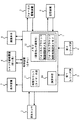
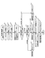
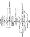
本発明の一実施形態である撮像装置(カメラ)の構成について、図1の全体ブロック図を参照して説明する。
<Configuration of the present invention>
The configuration of an imaging apparatus (camera) according to an embodiment of the present invention will be described with reference to the overall block diagram of FIG.
制御装置(CPU:Central Processing Unit)1は、撮像装置のすべての動作を制御する制御機能を有しており、内部には各種判断、演算を行うための演算手段10、時間をカウントするための時間カウント手段(タイマ手段)11、各種設定値を記憶しておく揮発性又は不揮発性のメモリ(フォーカスブラケット駆動幅設定メモリ、フォーカスブラケット撮影枚数設定メモリ)12などを含んでいる。必ずしもワンチップ構成でなくてもよく、画像処理チップなどを含む合成素子の構成でも、複数素子を含む制御ユニットを構成する構成でもよい。 A control device (CPU: Central Processing Unit) 1 has a control function for controlling all the operations of the imaging device, and internally includes a calculation means 10 for performing various determinations and calculations, and for counting time. A time counting means (timer means) 11 and a volatile or nonvolatile memory (focus bracket drive width setting memory, focus bracket photographing number setting memory) 12 for storing various setting values are included. The configuration may not necessarily be a one-chip configuration, and may be a configuration of a composite element including an image processing chip or a configuration of a control unit including a plurality of elements.
本発明の撮像装置において、制御装置1は、撮影に先立ち、フォーカス位置を変化させながら撮像画面内の複数箇所の画像信号を測光センサ2から取得し、コントラスト成分に応じた焦点評価値を取得する焦点評価値取得手段として機能する。また、制御装置1は、表示装置7とともに、ユーザがピントを合わせたい領域又はポイントを事前に指定する主要被写体指定手段として機能することもできる(実施例3)。 In the imaging apparatus of the present invention, the control device 1 acquires image signals at a plurality of locations in the imaging screen from the photometric sensor 2 while changing the focus position prior to shooting, and acquires a focus evaluation value corresponding to the contrast component. It functions as a focus evaluation value acquisition means. Further, the control device 1 can also function as a main subject specifying means for specifying in advance the area or point that the user wants to focus on, together with the display device 7 (Example 3).
測光センサ2は、被写体の明るさを検出するためのセンサであり、制御装置1からのコントロールにより駆動され、撮影範囲内(撮像画面内)の複数のポイントにおける被写体の明るさに関連する電気信号(画像信号)を検知し、制御装置1に入力する。また、なお、本発明のように、専用の測光センサ2を設けずに、撮像素子8による撮像データを用いて、複数領域の明るさを求める構成としてもよい。
The photometric sensor 2 is a sensor for detecting the brightness of the subject, and is driven by the control from the control device 1 and is an electric signal related to the brightness of the subject at a plurality of points within the shooting range (in the imaging screen). (Image signal) is detected and input to the control device 1. In addition, as in the present invention, the brightness of a plurality of areas may be obtained using image data obtained by the
第1レリーズSW(Switch)3は、撮影を行うためのレリーズSWの半押しによりONとなるスイッチである。また、第2レリーズSW(Switch)4は、撮影を行うためのレリーズSWの全押し(押し込み)によりONとなるスイッチである。図1では、それぞれ別々のスイッチとして記載されているが、本来は、同一のスイッチ上での操作(押し方)の違いにより、上記動作を行うものである。 The first release SW (Switch) 3 is a switch that is turned on by half-pressing the release SW for photographing. The second release SW (Switch) 4 is a switch that is turned on when the release SW for photographing is fully pressed (pressed). In FIG. 1, each switch is described as a separate switch, but originally, the above operation is performed by a difference in operation (how to push) on the same switch.
フォーカスレンズ駆動装置5、シャッタ駆動装置6は、撮影のためのフォーカス駆動及びシャッタ駆動を行うためのものである。また、フォーカス駆動装置5は、撮像素子8からの撮像データ(オートフォーカスのための評価データ)を取得しながらフォーカス駆動範囲(通常の場合は撮影可能な最短距離(最至近)〜無限遠までの)領域をスキャンすることで、合焦可能なポイントを探す役割も備えている。またシャッタ機構とは別に絞りを持ち絞りとシャッタを別々にコントロールする構成としてもよい。
The focus lens driving device 5 and the shutter driving device 6 are for performing focus driving and shutter driving for photographing. In addition, the focus driving device 5 acquires the imaging data (evaluation data for autofocus) from the
表示装置7は、撮影前のモニタリング表示、再生画像表示、事前設定などを行うためのメニュー表示などを行う液晶素子や、有機EL素子などの表示装置である。
The
記憶装置9は、撮影済み画像データを制御装置1にて所定の保存形式に変換後、保存するための保存装置であり、内蔵フラッシュメモリや、外部メモリカード、HDD等である。
撮像素子8は、被写体像を電気的に撮像することで得られた信号を制御装置1に入力するためのものであり、CCD、CMOSなどの素子である。
The
The
なお、図1における2〜9の各周辺装置は、駆動に必要な各種装置やドライバ等を含むものとする。 Note that each of the peripheral devices 2 to 9 in FIG. 1 includes various devices and drivers necessary for driving.
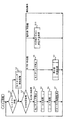
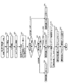
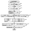
図2は、本発明の一実施形態である撮像装置における、撮影モード時の動作のフローチャートを示している。
通常(撮像装置のメインSWがONされている)状態では、カメラはモニタリング(撮影画像をLCD表示装置や他の表示手段にてモニタしながらの撮影準備状態)を行いながら操作SWが操作されるのを待っている。
FIG. 2 shows a flowchart of the operation in the shooting mode in the imaging apparatus according to the embodiment of the present invention.
In a normal state (when the main SW of the image pickup apparatus is turned on), the operation SW is operated while the camera performs monitoring (shooting preparation state while monitoring a photographed image with an LCD display device or other display means). Waiting for
すなわち、モニタリング状態において(ステップS1)、モニタリング状態が停止中の時は(ステップS1/停止中)、モニタリングを開始する処理を行ってから(ステップS2)、どのスイッチが操作されたかを判定する(ステップS3)。モニタリング状態がONの時は(ステップS1/ON中)、そのままどのスイッチが操作されたかを判定する(ステップS3)。 That is, in the monitoring state (step S1), when the monitoring state is stopped (step S1 / stopped), after starting the process of monitoring (step S2), it is determined which switch has been operated (step S2). Step S3). When the monitoring state is ON (during step S1 / ON), it is determined which switch is operated as it is (step S3).
その後は、レリーズ関連の操作が行われた場合はレリーズ動作を行い、また、他の操作が行われた場合は所定の動作を行った後、再びモニタリング状態に戻る。 Thereafter, when a release-related operation is performed, a release operation is performed, and when another operation is performed, a predetermined operation is performed, and then the monitoring state is restored.
すなわち、第1レリーズSW3が操作された場合(ステップS3/RL1SW ON処理)、モニタリングを停止し(ステップS4)、AE処理(自動露出処理)、AF処理(オートフォーカス処理)を行い(ステップS5,ステップS6)、フォーカス駆動処理を行って(ステップS7)、モニタリング状態に戻る。 That is, when the first release SW3 is operated (step S3 / RL1SW ON process), monitoring is stopped (step S4), AE process (automatic exposure process), and AF process (autofocus process) are performed (step S5). Step S6) performs focus drive processing (step S7), and returns to the monitoring state.
第2レリーズSW4が操作された場合(ステップS3/RL2SW ON処理)、モニタリングを停止し(ステップS8)、静止画記録処理を行い(ステップS9)、モニタリング状態に戻る。 When the second release SW4 is operated (step S3 / RL2SW ON process), the monitoring is stopped (step S8), the still image recording process is performed (step S9), and the monitoring state is restored.
第1レリーズSW3及び第2レリーズSW4以外のスイッチが操作された場合(ステップS3/他SW ON処理)、そのスイッチに対応した処理を行い(ステップS10)、モニタリング状態に戻る。 When a switch other than the first release SW3 and the second release SW4 is operated (step S3 / other SW ON process), a process corresponding to the switch is performed (step S10), and the process returns to the monitoring state.
無効操作がされた場合は(ステップS3/無効操作)、そのままモニタリング状態に戻る。 When the invalid operation is performed (step S3 / invalid operation), the monitoring state is returned as it is.
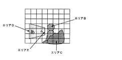
本発明の実施概念について、図3、図4を参照して説明する。
図3は、被写体の状況と位置関係を示したものであり、一番手前右側に岩があり、その奥に人物が配置され左側さらに奥に、黒板がななめ後方に向かって配置されているものとする。(黒板には近点、遠点がわかるように、「あ(近点)」「ん(遠点)」の文字が記述されているものとする。
The implementation concept of the present invention will be described with reference to FIGS.
Fig. 3 shows the situation and the positional relationship of the subject, with a rock on the right side of the foreground, a person placed behind it, and a blackboard placed behind the slanted back on the left side. And (It is assumed that the letters “a (near point)” and “n (far point)” are described on the blackboard so that the near point and the far point can be understood.
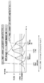
図4は、オートフォーカス合焦位置スキャン時の、焦点評価値(撮像成分の高周波成分にて算出され、画像のコントラストを示す)の変化曲線を示したものであり、図3に示した被写体をスキャンした場合の焦点評価値曲線の例を示している。 FIG. 4 shows a change curve of the focus evaluation value (calculated by the high-frequency component of the imaging component and indicating the contrast of the image) at the time of autofocus in-focus position scanning. The subject shown in FIG. The example of the focus evaluation value curve at the time of scanning is shown.
すなわち、最も遠い図3のエリアE(黒板遠点)はもっとも焦点評価値が小さく(低く)(すなわち合焦しづらい、合焦に自信がない)、エリアD(黒板近点)と、エリアC(岩)はエリアEよりは焦点評価値が大きく、同レベルであり、エリアB(人物)が最も焦点評価値が大きい(合焦しやすい、自信をもち合焦できる)ことがわかる。また、最も遠い図3のエリアE(黒板遠点)はもっとも焦点評価値形状がなだらかであり(すなわちピーク位置を認識しづらいため判定ミスが起こりやすい)、エリアD(黒板近点)と、エリアC(岩)はエリアEよりはピーク形状が尖鋭であるが標準的な形状であり、エリアB(人物)が最もピーク形状が尖鋭(ピーク判定が容易なため合焦判定精度が高い)ことがわかる。ここではいずれも合焦判定のための所定閾値よりは焦点評価値が大きい(高い)ものとしている。 That is, the farthest area E (blackboard far point) in FIG. 3 has the smallest focus evaluation value (low) (that is, it is difficult to focus and there is no confidence in focusing), and area D (blackboard near point) and area C It can be seen that (Rock) has a focus evaluation value larger than that of Area E, at the same level, and Area B (Person) has the largest focus evaluation value (easy to focus and can be focused with confidence). In addition, the farthest area E (blackboard far point) in FIG. 3 has the most gentle focus evaluation value shape (that is, it is difficult to recognize the peak position, and a determination error is likely to occur). C (rock) has a sharper peak shape than area E but is a standard shape, and area B (person) has the sharpest peak shape (higher focus determination accuracy because peak determination is easier). Recognize. Here, it is assumed that the focus evaluation value is larger (higher) than the predetermined threshold value for determining the focus.
このような場合にどのポイントを、カメラとしての合焦ポイントに選択するかということはシステム上の問題であり、例えば焦点評価値が最も高いポイントを選択しても良いし、焦点評価値が所定値(下)以上でかつもっとも近い部分(図4でいう右側にある極大値ポイント)を合焦ポイントに選択しても良いし、あるいは、撮影モードや事前規制により規制(ある距離以下しか選択しない)(全部の極大値が被写界深度内に収まる様になど)を設けてもよい。 In such a case, which point is selected as a focusing point as a camera is a problem on the system. For example, a point with the highest focus evaluation value may be selected, and the focus evaluation value is predetermined. The closest part (maximum value point on the right side in FIG. 4) that is greater than or equal to the value (lower) may be selected as the in-focus point, or restricted by the shooting mode or pre-regulation (select less than a certain distance) ) (Such that all the maximum values are within the depth of field).
以上が一般的な、コントラスト方式や山登り方式と言われるオートフォーカスの合焦ポイント検出、選択方法であり、実際の被写体の撮像信号を取り込みながらコントラストを比較するため他の方式(外部に位相差測距素子を設ける方法や、赤外LEDを受光位置センサで受光する方式)より比較的正確であり追加コストも不要である。 The above is a general autofocus point detection and selection method called contrast method or hill-climbing method, and other methods (external phase difference measurement) are used to compare the contrast while capturing the actual imaging signal of the subject. It is relatively more accurate than a method of providing a distance element or a method of receiving an infrared LED with a light receiving position sensor), and does not require additional cost.
ただし、コントラスト方式においても合焦ポイントの正確な再現性や、被写体状況の微妙な変化、撮影者の撮影意図(どこにピントを合わせたいかなどにより)、スキャン時のフォーカス間隔と時間の制約などにより完全に撮影者の意図を反映することができないことも有りうるため、1回の撮影で厳密な意味の合焦を得るための1手段として、フォーカスブラケット機能が一般的に用いられてきた。 However, even in the contrast method, due to the precise reproducibility of the in-focus point, subtle changes in the subject situation, the intention of the photographer (depending on where you want to focus), the focus interval and time constraints during scanning, etc. Since there is a possibility that the photographer's intention cannot be completely reflected, a focus bracket function has been generally used as one means for obtaining a strict meaning of focus in one shooting.
この機能は、自動露出におけるオートブラケット機能を基に考えられた方式であり、カメラとして選択した合焦ポイントをもとに、所定量前後に合焦ポイントをずらした画像も連続撮影して全て保存し、あとから撮影者に撮影意図にあった画像を選択してもらおうというものである。 This function was conceived based on the auto bracket function in automatic exposure. Based on the focus point selected as the camera, images with the focus point shifted around a predetermined amount are continuously shot and saved. Then, the photographer will be asked to select an image that suits his or her intention.
従来方式では、通常3枚(事前選択できるものもある)撮影であり、カメラの選択した合焦ポイントを前後に所定量(選択可能なものもある)ずらした画像を連続撮影し、すべて保存する。 In the conventional method, usually three shots (some of which can be selected in advance) are taken, and images obtained by shifting the in-focus point selected by the camera by a predetermined amount (some selectable) are continuously shot and stored. .
この方式は、撮影モードとしてわかりやすく、動作モードとしての統一性があるが、以下の欠点(課題)もある。
1つ目の課題は、撮影枚数があらかじめ決められているため、必要の無い場合も決まった枚数を撮影・保存してしまい、資源の有効利用の点から無駄が多い点である。
2つめの課題は、フォーカス間隔があらかじめ決まっているため、もっと細かいフォーカスステップにて撮影しないと変化が大きすぎる場合や、その逆にもっと変化が必要なのにもかかわらず小さな変化のまま撮影が終了し本当に欲しい撮影結果に届かない場合である。
This method is easy to understand as a shooting mode and has uniformity as an operation mode, but also has the following drawbacks (problems).
The first problem is that since the number of shots is determined in advance, a fixed number of shots are shot and stored even when it is not necessary, which is wasteful in terms of effective use of resources.
The second problem is that the focus interval is determined in advance, so if you do not shoot at a finer focus step, the change will be too large, or conversely, the shoot will end with a small change despite the need for more changes. This is the case when the desired result is not received.
いずれの場合も、事前に被写界深度を考慮して枚数、フォーカス間隔をマニュアルで設定しておく方法で有る程度は解決されるが、自動的に設定される訳ではなく、設定のための理論学習や経験が必要であり通常の撮影者にとってはかなりの困難さを伴う。 In either case, it can be solved to some extent by manually setting the number of images and the focus interval in consideration of the depth of field in advance, but it is not automatically set. It requires theoretical learning and experience, which is quite difficult for ordinary photographers.
本発明の撮像装置は、これらの課題を解決するためのものであり、通常のフォーカスブラケット撮影を行うだけで、カメラが自動的に決めた合焦ポイントの確からしさ(信頼性)に応じて、信頼性が高い場合は、ブラケット枚数を減らしたり、フォーカス間隔を細かく設定し、信頼性が低い場合は、ブラケット枚数を増やしたり、フォーカス間隔を広く設定して撮影者の意図する画像が得られやすくする効果を有することを主な特徴とする。 The imaging device of the present invention is for solving these problems, and by performing normal focus bracket shooting, depending on the accuracy (reliability) of the in-focus point automatically determined by the camera, If the reliability is high, reduce the number of brackets or set the focus interval finely. If the reliability is low, increase the number of brackets or set the focus interval wide to easily obtain the image intended by the photographer. The main feature is that it has the effect of
また、本発明の撮像装置は、無駄な撮影画像を撮影・保存しないという観点から撮影時消費電力の削減、保存メディアの有効利用という省エネルギー的な効果も有する。 The imaging apparatus of the present invention also has an energy saving effect of reducing power consumption during shooting and effective use of storage media from the viewpoint of not shooting and storing useless shot images.
以上説明した本発明の一実施形態である撮像装置の実施例について、以下にそれぞれ説明する。なお、各フローチャートを参照して説明する各実施例の動作は、図1に示す本実施形態の撮像装置において、制御装置1が、読み込まれたプログラムに従って、その他の各装置(各部)を制御することによって行われる。 Examples of the imaging apparatus according to the embodiment of the present invention described above will be described below. The operation of each example described with reference to each flowchart is performed by the control device 1 in the imaging apparatus according to the present embodiment illustrated in FIG. Is done by.
実施例1は、枚数設定を変更する実施例である。フォーカスブラケットを行うことは事前に設定されているものとする。 In the first embodiment, the number setting is changed. It is assumed that the focus bracketing is performed in advance.
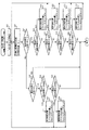
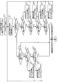
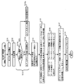
まず、図5のフローチャートを説明する。
レリーズが半押しされると(第1レリーズSW3がON処理されると)、モニタリングの停止処理(ステップS11)、AE(測光、測光演算など)処理(ステップS12)を行った後で、AF合焦ポイント検出のために、フォーカスレンズを所定ステップで動かし焦点評価値を取得するAF(スキャン処理)を実施する(ステップS13)。
First, the flowchart of FIG. 5 will be described.
When the release is half-pressed (when the first release SW3 is turned ON), after performing the monitoring stop process (step S11) and the AE (photometry, photometry calculation, etc.) process (step S12), AF In order to detect the focal point, AF (scanning process) for moving the focus lens in a predetermined step and acquiring a focus evaluation value is performed (step S13).
焦点評価値(各ポイントでの画像信号の高周波成分に関するデータ)の極大値の大きさ(高さ)を評価し、所定アルゴにて、カメラとしての合焦ポイントを決定する(ステップS14)。所定アルゴは、ここでは所定値以上でかつ一番近いもの<スキャン時の繰り出し量にて近いか遠いか判断可能>と設定するものとする。この部分のアルゴは、本発明の本質とは関係がないので種々の変更が可能であり、例えば一番評価値の高い極大値を合焦ポイントとするなどしてもよい。 The maximum value (height) of the focus evaluation value (data relating to the high-frequency component of the image signal at each point) is evaluated, and a focusing point as a camera is determined by a predetermined algorithm (step S14). Here, it is assumed that the predetermined algo is set to a value that is equal to or greater than a predetermined value and that is closest to <it is possible to determine whether the feed amount during scanning is close or far>. Since this part of the algo is not related to the essence of the present invention, various modifications are possible. For example, the maximum value with the highest evaluation value may be used as the in-focus point.
ここで決定した合焦ポイントの焦点評価値の大きさを検定(評価)する(ステップS15)。実施例1では2種類の所定値(1<大>、2<小>)を設けている。 The magnitude of the focus evaluation value of the focus point determined here is tested (evaluated) (step S15). In the first embodiment, two types of predetermined values (1 <large>, 2 <small>) are provided.
〈1〉所定値1は上限評価値(第1の所定値)を示し、決定された合焦ポイントの焦点評価値がこの数値より高い場合は(ステップS15/≧所定値1)、フォーカスレンズがこのポイントに来た時の高周波部分のコントラストがきわめて高く、合焦検出の信頼性が高いことを意味する。 <1> The predetermined value 1 indicates an upper limit evaluation value (first predetermined value). When the focus evaluation value of the determined focus point is higher than this value (step S15 / ≧ predetermined value 1), the focus lens is When this point is reached, the contrast of the high frequency portion is extremely high, which means that the focus detection reliability is high.
〈2〉所定値2は下限評価値(第2の所定値)を示し、決定された合焦ポイントの焦点評価値の大きさがこの数値より低い場合(合焦選定基準よりは上に設定した場合)は(ステップS15/<所定値1、ステップS17/<所定値2)、合焦選定としては問題がない(合焦不能とする程低くはないが)が、高周波成分のコントラストが低く、合焦検出の信頼性が比較的低いことを意味する。 <2> Predetermined value 2 indicates a lower limit evaluation value (second predetermined value), and when the focus evaluation value of the determined focus point is lower than this value (set above the focus selection criterion) In the case) (step S15 / <predetermined value 1, step S17 / <predetermined value 2), there is no problem as a focus selection (although not so low as to make focusing impossible), the contrast of the high frequency component is low, This means that the reliability of focus detection is relatively low.
〈3〉所定値1,2の間にある場合は(ステップS15/<所定値1、ステップS17/≧所定値2)、決定された合焦ポイントの焦点評価値の大きさが標準的で、通常レベルの信頼性であることを意味する。 <3> When the value is between the predetermined values 1 and 2 (step S15 / <predetermined value 1, step S17 / ≧ predetermined value 2), the size of the focus evaluation value of the determined in-focus point is standard, Means a normal level of reliability.
実施例1では、上記〈1〉〜〈3〉のどのレベルで有るかを判定した後、通常のフォーカスブラケット撮影枚数(標準枚数。ここでは3枚)を自動的に設定変更(増減する)。この設定変更は、メモリ12のフォーカスブラケット撮影枚数設定メモリに予め記憶されている設定内容に基づいて行われる。
In the first embodiment, after determining which level of <1> to <3>, the normal focus bracket shooting number (standard number, here three) is automatically changed (increased or decreased). This setting change is performed based on the setting contents stored in advance in the focus bracket shooting number setting memory of the
すなわち、信頼性がきわめて高い上記〈1〉のような場合には(ステップS15/≧所定値1)、合焦部のみの撮影で良し(撮影枚数を1枚とセット)とする(ステップS16)。 That is, in the case of <1>, which has extremely high reliability (step S15 / ≧ predetermined value 1), it is acceptable to shoot only the in-focus portion (set the number of shots to be one) (step S16). .
逆に、信頼性が低い〈2〉のような場合には(ステップS15/<所定値1、ステップS17/<所定値2)、撮影枚数を+2枚し、5枚とし、合焦の確率を自動的に増やす(撮影枚数5枚をセット)制御とする(ステップS18)。 On the other hand, in the case of <2> where the reliability is low (step S15 / <predetermined value 1, step S17 / <predetermined value 2), the number of shots is +2 and set to 5, and the probability of focusing is set. The control automatically increases (sets the number of shots 5) (step S18).
標準的な〈3〉のような場合には(ステップS15/<所定値1、ステップS17/≧所定値2)、通常通りの撮影枚数(撮影枚数3枚セット)とする(ステップS19)。 In the case of standard <3> (step S15 / <predetermined value 1, step S17 / ≧ predetermined value 2), the number of shots is set as usual (a set of three shots) (step S19).
なお、信頼性が高い場合にも、必ずしも1枚のみの撮影で撮影意図を反映できるとは限らない場合(コントラストの高い人物撮影において手前の目にきちんと合焦させたい様な場合など)には、標準撮影枚数を5枚〜7枚程度に設定して、そこから2枚程度削減する(必ず3枚以上は撮影する)構成としてもよいし、逆に焦点評価値が低い場合には、さらに枚数を増やす構成(+10枚など)としても良いし、増減枚数を必ずしも対称的に設定する必要もない。ここでは、フローチャートが煩雑になり説明も冗長となるため、あえてシンプルな構成にて説明している。 Note that even if the reliability is high, it is not always possible to reflect the shooting intention by shooting only one image (such as when you want to focus properly on the front eye in high-contrast portrait shooting). The standard number of shots may be set to about 5 to 7 and then reduced by about 2 (by taking 3 or more images), or conversely if the focus evaluation value is low, A configuration in which the number of sheets is increased (such as +10 sheets) may be used, and the number of sheets to be increased or decreased is not necessarily set symmetrically. Here, since the flowchart is complicated and the description is redundant, the description is given with a simple configuration.
セット後、所定のフォーカスブラケット間隔(ここでは、パルスモータ方式のフォーカス制御を想定しており、どのくらいのフォーカスステップ間隔にてフォーカスをずらして撮影するかを示している)を設定する(ステップS20)。ここでは、通常2ステップ間隔と設定するものとしている。この部分はカメラ構成(焦点距離やレンズ構成、レンズのF値や絞り値、必要とされるフォーカス精度などにより異なるが、2ステップに意味があるわけではなく、通常のフォーカスブラケットのフォーカス間隔をセットするという意味である。 After the setting, a predetermined focus bracket interval is set (here, it is assumed that pulse motor focus control is performed and the focus step interval is used to indicate that the focus is shifted) (step S20). . Here, the interval is usually set to 2 steps. This part varies depending on the camera configuration (focal length, lens configuration, lens F value and aperture value, required focus accuracy, etc., but the two steps are not meaningful, and the focus interval of the normal focus bracket is set. It means to do.
次にフォーカスブラケットの現在枚数カウンタに1をセットし(ステップS20)、決定された合焦ポイントにフォーカスレンズをセット(駆動)する(ステップS21)。 Next, 1 is set in the current number counter of the focus bracket (step S20), and the focus lens is set (driven) at the determined focus point (step S21).
次に、図6のフローチャートを説明する。
図5のステップS21の後、レリーズが押し込んで全押しされると(第2レリーズSW4がON処理されると)、モニタリング停止の後(ステップS22)、ステップS23〜S37において、セットされた撮影枚数と、現在の撮影カウンタの内容により、撮影制御される。ステップS23では、静止画像の撮影及び記録が行われるとともに、現在枚数に+1をするカウントが行われる(図5のステップS20にて現在の撮影枚数「1」がカウントされているので、1枚目の撮影後は、現在の撮影枚数「1」に+1をカウントし、現在枚数が「2」となる)。
Next, the flowchart of FIG. 6 will be described.
After step S21 of FIG. 5, when the release is pushed in and fully pressed (when the second release SW4 is turned on), after the monitoring is stopped (step S22), the set number of shots is set in steps S23 to S37. Then, shooting control is performed according to the contents of the current shooting counter. In step S23, a still image is shot and recorded, and the current number is incremented by 1 (the current number of shots “1” is counted in step S20 in FIG. 5). ), +1 is added to the current number of shots “1”, and the current number of shots becomes “2”).
例えば、撮影枚数が1枚にセットされている場合は(図5のステップS16の場合)、『決定合焦ポイント撮影』のみで撮影を終了する。 For example, when the number of shots is set to 1 (in the case of step S16 in FIG. 5), the shooting is ended only by “determined focus point shooting”.
すなわち、詳細は次のようになる。
モニタリング停止の後(ステップS22)、決定した合焦ポイントで1枚目を撮影し、現在の撮影枚数を2枚目とカウントした後(ステップS23)、撮影枚数が5枚にセットされているか否かを判断する(ステップS24)。撮影枚数は5枚にセットされていないので(ステップS24/NO)、次に進み、撮影枚数が3枚にセットされているか否かを判断する(ステップS25)。撮影枚数は3枚にセットされていないので(ステップS25/NO)、撮影終了となる。
That is, the details are as follows.
After the monitoring is stopped (step S22), the first picture is taken at the determined focus point, the current number of shots is counted as the second (step S23), and whether the number of shots is set to five. Is determined (step S24). Since the number of shots is not set to 5 (step S24 / NO), it proceeds to the next, and it is determined whether or not the number of shots is set to 3 (step S25). Since the number of shots is not set to 3 (step S25 / NO), shooting ends.
撮影枚数が3枚にセットされている場合は(図5のステップS19の場合)、『決定合焦ポイント撮影』→『−1×(通常フォーカス間隔:2Step)撮影』→『+1×(通常フォーカス間隔:2Step)撮影』が行われて撮影終了となる。 When the number of shots is set to 3 (in the case of step S19 in FIG. 5), “determined focus point shooting” → “−1 × (normal focus interval: 2 steps) shooting” → “+ 1 × (normal focus) Interval: 2 Step) Shooting ”is performed and the shooting ends.
すなわち、詳細は次のようになる。
モニタリング停止の後(ステップS22)、決定した合焦ポイントで1枚目を撮影し、現在の撮影枚数を2枚目とカウントした後(ステップS23)、撮影枚数が5枚にセットされているか否かを判断する(ステップS24)。撮影枚数は5枚にセットされていないので(ステップS24/NO)、次に進み、撮影枚数が3枚にセットされているか否かを判断する(ステップS25)。撮影枚数は3枚にセットされているので(ステップS25/YES)、次に進み、現在の撮影枚数が2枚目か否かを判断する(ステップS26)。
That is, the details are as follows.
After the monitoring is stopped (step S22), the first picture is taken at the determined focus point, the current number of shots is counted as the second (step S23), and whether the number of shots is set to five. Is determined (step S24). Since the number of shots is not set to 5 (step S24 / NO), it proceeds to the next, and it is determined whether or not the number of shots is set to 3 (step S25). Since the number of shots is set to three (step S25 / YES), the process proceeds to the next to determine whether or not the current number of shots is the second (step S26).
現在の撮影枚数は2枚目であるので(ステップS26/YES)、選択した合焦位置(−1×2Step)にフォーカスレンズをセットし(ステップS27)、撮影及び現在枚数をカウントする(ステップS23)。ここで、現在の撮影枚数は3枚目となる。再び、ステップS24、S25、S26で判断を行った後、現在の撮影枚数が3枚目か否かを判断する(ステップS28)。 Since the current number of shots is the second (step S26 / YES), the focus lens is set at the selected focus position (−1 × 2 Step) (step S27), and the number of shots and the current number is counted (step S23). ). Here, the current number of shots is the third. After making the determination again in steps S24, S25, and S26, it is determined whether or not the current number of shots is the third (step S28).
現在の撮影枚数は3枚目であるので(ステップS28/YES)、選択した合焦位置(+1×2Step)にフォーカスレンズをセットし(ステップS29)、撮影及び現在枚数をカウントする(ステップS23)。ここで、現在の撮影枚数は4枚目となる。再び、ステップS24、S25、S26、S28で判断を行い、現在の撮影枚数は4枚目であるので(ステップS28/NO)、撮影終了となる。 Since the current number of shots is the third (step S28 / YES), the focus lens is set at the selected focus position (+ 1 × 2 Step) (step S29), and the number of shots and the current number of shots is counted (step S23). . Here, the current number of shots is the fourth. The determination is again made in steps S24, S25, S26, and S28, and since the current number of shots is the fourth (step S28 / NO), the shooting ends.
例えば、撮影枚数が5枚にセットされている場合は(図5のステップS18の場合)、『決定合焦ポイント撮影』→『−2×(通常設定間隔:2Step)撮影』→『−1×(通常フォーカス間隔:2Step)撮影』→『+1×(通常フォーカス間隔:2Step)撮影』→『+2×(通常フォーカス間隔:2Step)撮影』が行われて撮影終了となる。 For example, when the number of shots is set to 5 (in the case of step S18 in FIG. 5), “determined focus point shooting” → “−2 × (normal setting interval: 2 Step) shooting” → “−1 × (Normal focus interval: 2 steps) shooting ”→“ + 1 × (normal focus interval: 2 steps) shooting ”→“ + 2 × (normal focus interval: 2 steps) shooting ”is performed, and the shooting is completed.
すなわち、詳細は次のようになる。
モニタリング停止の後(ステップS22)、決定した合焦ポイントで1枚目を撮影し、現在の撮影枚数を2枚目とカウントした後(ステップS23)、撮影枚数が5枚にセットされているか否かを判断する(ステップS24)。撮影枚数は5枚にセットされているので(ステップS24/YES)、次に進み、現在の撮影枚数が2枚目であるか否かを判断する(ステップS30)。
That is, the details are as follows.
After the monitoring is stopped (step S22), the first picture is taken at the determined focus point, the current number of shots is counted as the second (step S23), and whether the number of shots is set to five. Is determined (step S24). Since the number of shots is set to 5 (step S24 / YES), the process proceeds to the next, and it is determined whether or not the current number of shots is the second (step S30).
現在の撮影枚数は2枚目であるので(ステップS30/YES)、選択した合焦位置(−2×2Step)にフォーカスレンズをセットし(ステップS31)、撮影及び現在枚数をカウントする(ステップS23)。ここで、現在の撮影枚数は3枚目となる。再び、ステップS24、S30で判断を行った後、現在の撮影枚数が3枚目か否かを判断する(ステップS32)。 Since the current number of shots is the second (step S30 / YES), the focus lens is set at the selected focus position (-2 × 2 Step) (step S31), and the number of shots and the current number of shots is counted (step S23). ). Here, the current number of shots is the third. After making the determination again in steps S24 and S30, it is determined whether or not the current number of shots is the third (step S32).
現在の撮影枚数は3枚目であるので(ステップS32/YES)、選択した合焦位置(−1×2Step)にフォーカスレンズをセットし(ステップS33)、撮影及び現在枚数をカウントする(ステップS23)。ここで、現在の撮影枚数は4枚目となる。再び、ステップS24、S30、S32で判断を行った後、現在の撮影枚数が4枚目か否かを判断する(ステップS34)。 Since the current number of shots is the third (step S32 / YES), the focus lens is set at the selected focus position (−1 × 2 Step) (step S33), and the number of shots and the current number is counted (step S23). ). Here, the current number of shots is the fourth. After making the determination again in steps S24, S30, and S32, it is determined whether or not the current number of shots is the fourth (step S34).
現在の撮影枚数は4枚目であるので(ステップS34/YES)、選択した合焦位置(+1×2Step)にフォーカスレンズをセットし(ステップS35)、撮影及び現在枚数をカウントする(ステップS23)。ここで、現在の撮影枚数は5枚目となる。再び、ステップS24、S30、S32、S34で判断を行った後、現在の撮影枚数が5枚目か否かを判断する(ステップS36)。 Since the current number of shots is the fourth (step S34 / YES), the focus lens is set at the selected focus position (+ 1 × 2 Step) (step S35), and the number of shots and the current number of shots is counted (step S23). . Here, the current number of shots is the fifth. After making a determination again in steps S24, S30, S32, and S34, it is determined whether or not the current number of shots is the fifth (step S36).
現在の撮影枚数は5枚目であるので(ステップS36/YES)、選択した合焦位置(+2×2Step)にフォーカスレンズをセットし(ステップS37)、撮影及び現在枚数をカウントする(ステップS23)。ここで、現在の撮影枚数は6枚目となる。再び、ステップS24、S30、S32、S34で判断を行った後、現在の撮影枚数が5枚目か否かを判断する(ステップS36)。現在の撮影枚数は6枚目であるので(ステップS36/NO)、撮影終了となる。 Since the current number of shots is the fifth (step S36 / YES), the focus lens is set at the selected focus position (+ 2 × 2 Step) (step S37), and the number of shots and the current number is counted (step S23). . Here, the current number of shots is the sixth. After making a determination again in steps S24, S30, S32, and S34, it is determined whether or not the current number of shots is the fifth (step S36). Since the current number of shots is the sixth shot (step S36 / NO), shooting ends.
図5のレリーズ半押し動作の部分で述べたように、ここに設定した枚数はあくまでも説明を簡略化するために標準枚数を減らした事例であり、信頼性の高い合焦ポイントの場合でも3枚以上の撮影を行えるように構成するのが撮影者の意図する部分にきちんとフォーカスを合わせるというフォーカスブラケットモード本来の意図には合致しているので、そのように構成しても良いし、評価値と撮影枚数の設定段階数も3段階でなく多段階に構成しても良い。 As described in the release half-press operation portion of FIG. 5, the number of sheets set here is an example in which the standard number is reduced to simplify the explanation, and even in the case of a highly reliable focusing point, three sheets are used. Since it is configured so that the above shooting can be performed, it matches the original intention of the focus bracket mode of properly focusing on the part intended by the photographer, so it may be configured as such, and the evaluation value and The number of steps for setting the number of shots may be configured in multiple stages instead of three.
以上の実施例により、AF合焦ポイントの信頼性に応じて自動的に撮影枚数を増減することで、原理的に合様可能性(信頼性)が比較的高い場合には撮影枚数を削減して無駄な撮影を防止し、合焦可能性(信頼性)が比較的低い場合には撮影枚数を増やして、より合焦が得られる確率を増やすことができるインテリジェントな撮像装置の合焦機構とすることができる。 According to the above embodiment, the number of shots is automatically increased / decreased according to the reliability of the AF in-focus point, thereby reducing the number of shots in principle when the possibility of matching (reliability) is relatively high. An intelligent imaging device focusing mechanism that can prevent unnecessary shooting and increase the number of shots when the focusability (reliability) is relatively low, thereby increasing the probability of achieving more focus. can do.
また、コスト面でも全て制御装置内での処理追加にて構成できるため、コストアップすることがなく、安価に構成することが可能である。 Further, since all can be configured by adding processing within the control device in terms of cost, it is possible to configure at low cost without increasing the cost.
実施例2は、フォーカス間隔設定を変更する実施例である。フォーカスブラケットを行うことは事前に設定されているものとする。 The second embodiment is an embodiment in which the focus interval setting is changed. It is assumed that the focus bracketing is performed in advance.
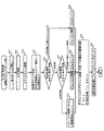
まず、図7のフローチャートを説明する。
レリーズが半押しされると(第1レリーズSW3がON処理されると)、モニタリングの停止処理(ステップS41)、AE(測光、測光演算など)処理(ステップS42)を行った後で、AF合焦ポイント検出のために、フォーカスレンズを所定ステップで動かし焦点評価値を取得するAF(スキャン処理)を実施する(ステップS43)。
First, the flowchart of FIG. 7 will be described.
When the release is half-pressed (when the first release SW3 is turned ON), after performing the monitoring stop process (step S41) and the AE (photometry, photometry calculation, etc.) process (step S42), AF In order to detect the focal point, AF (scanning process) is performed in which the focus lens is moved in predetermined steps to obtain a focus evaluation value (step S43).
焦点評価値(各ポイントでの画像信号の高周波成分に関するデータ)の極大値の大きさ(高さ)を評価し、所定アルゴにて、カメラとしての合焦ポイントを決定する(ステップS44)。所定アルゴは、ここでは所定値以上でかつ一番近いもの<スキャン時の繰り出し量にて近いか遠いか判断可能>と設定するものとする。この部分のアルゴは、本発明の本質とは関係がないので種々の変更が可能であり、例えば一番評価値の高い極大値を合焦ポイントとするなどしてもよい。 The maximum value (height) of the focus evaluation value (data relating to the high-frequency component of the image signal at each point) is evaluated, and a focusing point as a camera is determined by a predetermined algorithm (step S44). Here, it is assumed that the predetermined algo is set to a value that is equal to or greater than a predetermined value and that is closest to <it is possible to determine whether the feed amount during scanning is close or far>. Since this part of the algo is not related to the essence of the present invention, various modifications are possible. For example, the maximum value with the highest evaluation value may be used as the in-focus point.
ここで決定した合焦ポイントの焦点評価値の大きさを検定(評価)する(ステップS45)。実施例2では2種類の所定値(1<大>、2<小>)を設けている。 The magnitude of the focus evaluation value of the focus point determined here is tested (evaluated) (step S45). In the second embodiment, two types of predetermined values (1 <large>, 2 <small>) are provided.
〈1〉所定値1は上限評価値(第1の所定値)を示し、決定された合焦ポイントの焦点評価値がこの数値より高い場合は(ステップS45/≧所定値1)、フォーカスレンズがこのポイントに来た時の高周波部分のコントラストがきわめて高く、合焦検出の信頼性が高いことを意味する。 <1> The predetermined value 1 indicates an upper limit evaluation value (first predetermined value). When the focus evaluation value of the determined focus point is higher than this value (step S45 / ≧ predetermined value 1), the focus lens is When this point is reached, the contrast of the high frequency portion is extremely high, which means that the focus detection reliability is high.
〈2〉所定値2は下限評価値(第2の所定値)を示し、決定された合焦ポイントの焦点評価値の大きさがこの数値より低い場合(合焦選定基準よりは上に設定した場合)は(ステップS45/<所定値1、ステップS47/<所定値2)、合焦選定としては問題がない(合焦不能とする程低くはないが)が、高周波成分のコントラストが低く、合焦検出の信頼性が比較的低いことを意味する。 <2> Predetermined value 2 indicates a lower limit evaluation value (second predetermined value), and when the focus evaluation value of the determined focus point is lower than this value (set above the focus selection criterion) (Step S45 / <predetermined value 1, step S47 / <predetermined value 2), there is no problem as the focus selection (although not so low as to make focusing impossible), but the contrast of the high frequency component is low, This means that the reliability of focus detection is relatively low.
〈3〉所定値1,2の間にある場合は(ステップS45/<所定値1、ステップS47/≧所定値2)、決定された合焦ポイントの焦点評価値の大きさが標準的で、通常レベルの信頼性であることを意味する。 <3> When the value is between the predetermined values 1 and 2 (step S45 / <predetermined value 1, step S47 / ≧ predetermined value 2), the focus evaluation value of the determined in-focus point is standard, Means a normal level of reliability.
実施例2では、上記〈1〉〜〈3〉のどのレベルで有るかを判定した後、通常のフォーカスブラケット撮影のフォーカス間隔(2step)を自動的に設定変更(増減する)。この設定変更は、メモリ12のフォーカスブラケット駆動幅設定メモリに予め記憶されている設定内容に基づいて行われる。
In Example 2, after determining which level of <1> to <3>, the focus interval (2 steps) for normal focus bracket shooting is automatically changed (increased or decreased). This setting change is performed based on the setting contents stored in advance in the focus bracket drive width setting memory of the
すなわち、信頼性がきわめて高い上記〈1〉のような場合には(ステップS45/≧所定値1)、フォーカス間隔を小さく(1stepに)設定し、決定合焦ポイントのごく近傍前後のみの撮影とする(ステップS46)。 That is, in the case of <1> where the reliability is extremely high (step S45 / ≧ predetermined value 1), the focus interval is set to be small (to 1 step), and photographing only before and after the vicinity of the determined in-focus point is performed. (Step S46).
逆に、信頼性が低い〈2〉のような場合には(ステップS45/<所定値1、ステップS47/<所定値2)、フォーカス間隔を通常より広く(3 stepに)設定し、合焦できる確率をできるだけ増やす制御とする(ステップS48)。 Conversely, in the case of <2> where the reliability is low (step S45 / <predetermined value 1, step S47 / <predetermined value 2), the focus interval is set wider than usual (to 3 steps) and focused. Control is performed to increase the possible probability as much as possible (step S48).
標準的な〈3〉のような場合には(ステップS45/<所定値1、ステップS47/≧所定値2)、通常通りのフォーカス間隔(2 stepに)設定するものとする(ステップS49)。 In the case of the standard <3> (step S45 / <predetermined value 1, step S47 / ≧ predetermined value 2), the normal focus interval (2 steps) is set (step S49).
信頼性が高い場合の設定で、フォーカス間隔が細かいので前後の設定枚数のみの撮影で撮影意図を反映できるとは限らない場合(コントラストの高い人物撮影において手前の目にきちんと合焦させたい様な場合など)には、撮影枚数を同時に増やす構成(振り幅を一定とする)構成や、撮影枚数も同時に減らす構成(無駄な撮影はできるだけしない)構成としてもよい。逆に焦点評価値が低い場合には、同時に枚数を増やす構成(+10枚など)としさらに合焦できる確率を増やしても良い、撮影枚数は減らす(振り幅は一定とする)構成としてもよいし、それらの組み合わせ構成としても良い。フローチャートが煩雑になり説明も冗長となるため、あえてシンプルな構成(フォーカスブラケット撮影枚数は5枚で固定)にて説明している。 This is a setting with high reliability, and the focus interval is fine, so it is not always possible to reflect the intention of shooting by shooting only the set number of frames before and after (such as when you want to focus properly on the front eye when shooting a high-contrast person For example, a configuration in which the number of shots is increased at the same time (a constant swing is set), or a configuration in which the number of shots is also reduced at the same time (unnecessary shooting is performed as little as possible) may be used. On the other hand, when the focus evaluation value is low, it is possible to increase the number of images at the same time (such as +10), to further increase the probability of focusing, or to decrease the number of shots (with a constant swing width). These may be combined. Since the flowchart is complicated and the description is redundant, the description is made with a simple configuration (the number of focus brackets is fixed at 5).
その後、所定のフォーカスブラケット枚を設定する(ステップS50)。ここでは、実施例1のように、標準枚数を5枚に設定するものとしている。なお、この部分は、カメラ構成(焦点距離やレンズ構成、レンズのF値や絞り値、必要とされるフォーカス精度など)により異なるが、5枚撮影に意味があるわけではなく、通常のフォーカスブラケットの撮影枚数をセットするという意味である。 Thereafter, a predetermined focus bracket sheet is set (step S50). Here, as in the first embodiment, the standard number is set to five. Note that this part varies depending on the camera configuration (focal length, lens configuration, lens F-number and aperture value, required focus accuracy, etc.), but it does not make sense for five-frame shooting. This means that the number of shots is set.
次に、フォーカスブラケットの現在枚数カウンタに1をセットし(ステップS50)、決定された合焦ポイントにフォーカスレンズをセット(駆動)する(ステップS51)。 Next, 1 is set in the current number counter of the focus bracket (step S50), and the focus lens is set (driven) at the determined focus point (step S51).
次に、図8のフローチャートを説明する。
図7のステップS51の後、レリーズが押し込んで全押しされると(第2レリーズSW4がON処理されると)、モニタリング停止の後(ステップS52)、ステップS53〜S61において、セットされた撮影枚数と、現在の撮影カウンタの内容により、撮影制御される。ステップS53は、図6のステップS23と同じ動作である。
Next, the flowchart of FIG. 8 will be described.
After step S51 in FIG. 7, when the release is pushed in and fully pressed (when the second release SW4 is turned on), after the monitoring is stopped (step S52), the set number of shots is set in steps S53 to S61. Then, shooting control is performed according to the contents of the current shooting counter. Step S53 is the same operation as step S23 of FIG.
例えば、フォーカス間隔に2stepがセットされている場合は(図7のステップS49の場合)、『決定合焦ポイント撮影』→『−2×(設定フォーカス間隔:2Step)撮影』→『−1×(設定フォーカス間隔:2Step)撮影』→『+1×(設定フォーカス間隔:2Step)撮影』→『+2×(設定フォーカス間隔:2Step)撮影』が行われて撮影終了となる。 For example, when 2 steps is set as the focus interval (in the case of step S49 in FIG. 7), “determined focus point shooting” → “−2 × (set focus interval: 2 steps) shooting” → “−1 × ( “Set focus interval: 2 Step) shooting” → “+ 1 × (Set focus interval: 2 Step) shooting” → “+ 2 × (Set focus interval: 2 Step) shooting” is performed, and the shooting ends.
すなわち、詳細は次のようになる。
モニタリング停止の後(ステップS52)、決定した合焦ポイントで1枚目を撮影し、現在の撮影枚数を2枚目とカウントした後(ステップS53)、現在の撮影枚数が2枚目であるか否かを判断する(ステップS54)。
That is, the details are as follows.
After monitoring is stopped (step S52), the first shot is taken at the determined focus point, the current shot number is counted as the second shot (step S53), and the current shot number is the second shot. It is determined whether or not (step S54).
現在の撮影枚数は2枚目であるので(ステップS54/YES)、選択した合焦位置(−2×2Step)にフォーカスレンズをセットし(ステップS55)、撮影及び現在枚数をカウントする(ステップS53)。ここで、現在の撮影枚数は3枚目となる。再び、ステップS54で判断を行った後、現在の撮影枚数が3枚目か否かを判断する(ステップS56)。 Since the current number of shots is the second (step S54 / YES), the focus lens is set at the selected focus position (-2 × 2 Step) (step S55), and the number of shots and the current number of shots is counted (step S53). ). Here, the current number of shots is the third. After making the determination again in step S54, it is determined whether or not the current number of shots is the third (step S56).
現在の撮影枚数は3枚目であるので(ステップS56/YES)、選択した合焦位置(−1×2Step)にフォーカスレンズをセットし(ステップS57)、撮影及び現在枚数をカウントする(ステップS53)。ここで、現在の撮影枚数は4枚目となる。再び、ステップS54、S56で判断を行った後、現在の撮影枚数が4枚目か否かを判断する(ステップS58)。 Since the current number of shots is the third shot (step S56 / YES), the focus lens is set at the selected focus position (−1 × 2 Step) (step S57), and the number of shots and the current number of shots is counted (step S53). ). Here, the current number of shots is the fourth. After making the determination again in steps S54 and S56, it is determined whether or not the current number of shots is the fourth (step S58).
現在の撮影枚数は4枚目であるので(ステップS58/YES)、選択した合焦位置(+1×2Step)にフォーカスレンズをセットし(ステップS59)、撮影及び現在枚数をカウントする(ステップS53)。ここで、現在の撮影枚数は5枚目となる。再び、ステップS54、S56、S58で判断を行った後、現在の撮影枚数が5枚目か否かを判断する(ステップS60)。 Since the current number of shots is the fourth (step S58 / YES), the focus lens is set at the selected focus position (+ 1 × 2 Step) (step S59), and the number of shots and the current number is counted (step S53). . Here, the current number of shots is the fifth. After making the determination again in steps S54, S56, and S58, it is determined whether or not the current number of shots is the fifth (step S60).
現在の撮影枚数は5枚目であるので(ステップS60/YES)、選択した合焦位置(+2×2Step)にフォーカスレンズをセットし(ステップS61)、撮影及び現在枚数をカウントする(ステップS53)。ここで、現在の撮影枚数は6枚目となる。再び、ステップS54、S56、S58で判断を行った後、現在の撮影枚数が5枚目か否かを判断する(ステップS60)。現在の撮影枚数は6枚目であるので(ステップS60/NO)、撮影終了となる。 Since the current number of shots is the fifth (step S60 / YES), the focus lens is set at the selected focus position (+ 2 × 2 Step) (step S61), and the number of shots and the current number is counted (step S53). . Here, the current number of shots is the sixth. After making the determination again in steps S54, S56, and S58, it is determined whether or not the current number of shots is the fifth (step S60). Since the current number of shots is the sixth shot (step S60 / NO), the shooting ends.
図7のレリーズ半押し動作の部分で述べたように、ここに設定したフォーカス間隔はあくまでも説明を簡略化するために、適当なフォーカス間隔にて説明しており、フォーカス間隔ステップ数自体に意味はない。また、所定撮影枚数もフローを簡略化するため少なめに設定してあり、信頼性の高い合焦ポイントの場合でも5枚以上の撮影を行えるように構成し、撮影者の意図する部分に完全にきちんとフォーカスを合わせるという新たなフォーカスブラケットモードの意図に合致するように構成しても良い。撮像素子読み出し速度や、画像処理速度の高速化などもこの構成の追い風となる。評価値とフォーカス間隔の設定段階数も3段階でなく多段階に構成しても良い。 As described in the release half-press operation portion of FIG. 7, the focus interval set here is described with an appropriate focus interval for the sake of simplicity, and the meaning of the focus interval step number itself is Absent. In addition, the predetermined number of shots is set to a small number to simplify the flow, and it is configured so that five or more shots can be taken even in the case of a highly reliable focus point. You may comprise so that it may match the intention of the new focus bracket mode of adjusting a focus properly. An imaging element reading speed and an increase in image processing speed also serve as a tailwind of this configuration. The number of stages for setting the evaluation value and the focus interval may be configured in multiple stages instead of three.
以上の実施例により、AF合焦ポイントの信頼性に応じて自動的にフォーカスブラケット時のフォーカス間隔を増減することで、原理的に合様可能性(信頼性)が比較的高い場合にはフォーカス間隔を狭くしてよりシビアに合焦ポイント近傍の画像を取得し、合焦可能性(信頼性)が比較的低い場合にはフォーカス間隔を広くして、より合焦が得られる確率を増やすことができるインテリジェントな撮像装置の合焦機構とすることができる。 According to the above embodiment, the focus interval at the time of the focus bracket is automatically increased or decreased according to the reliability of the AF in-focus point. Narrow the interval to acquire images near the in-focus point more severely, and if the focus possibility (reliability) is relatively low, widen the focus interval to increase the probability of obtaining more in-focus. It is possible to provide a focusing mechanism for an intelligent image pickup apparatus capable of
また、コスト面でも全て制御装置内での処理追加にて構成できるため、コストアップすることがなく、安価に構成することが可能である。 Further, since all can be configured by adding processing within the control device in terms of cost, it is possible to configure at low cost without increasing the cost.
実施例1のフローチャートである図5では、事前に合焦ポイントや、合焦領域を指定する場合である(フォーカスブラケットを行うことは事前に設定されているものとする)。合焦ポイントや合焦領域事前指定方法は本発明の本質では無いため、ここでの詳細な説明は控えるが、一般的な方法としては、タッチパネルにより撮影予定範囲をモニタリングしている時に、合焦したい任意の所定領域や、所定被写体、エッジなどをタッチして指定する方式や、あらかじめ合焦が可能な領域をモニタに表示しておき、それをSW操作やメニュー操作により選択する方式などがある。また、顔認識などにて発見された複数の顔をモニタに表示し、合焦したい顔をSWやタッチパネルにより選択する方法などもある。将来的には、被写体領域をカメラにて自動分割し、領域表示した上で、合焦したい領域をSWやタッチパネルにて選択させる方式も考えられる。以上何れかの方法により、事前に合焦させたい領域が指定されているものとする。 FIG. 5 which is a flowchart of the first embodiment is a case where a focus point and a focus area are designated in advance (assuming that the focus bracketing is set in advance). Since the focus point and focus area prior designation method are not the essence of the present invention, a detailed description thereof will be omitted. However, as a general method, the focus is adjusted when the scheduled shooting range is monitored by the touch panel. There are a method of touching and specifying an arbitrary predetermined area to be desired, a predetermined subject, an edge, and the like, a method of displaying a focusable area in advance on a monitor, and selecting it by SW operation or menu operation, etc. . There is also a method of displaying a plurality of faces found by face recognition on a monitor and selecting a face to be focused by SW or a touch panel. In the future, there may be a method in which the subject area is automatically divided by the camera, the area is displayed, and the area to be focused is selected by the SW or the touch panel. It is assumed that the region to be focused is designated in advance by any of the above methods.
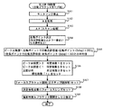
まず、図9のフローチャートを説明する。フォーカスブラケットを行うことは事前に設定されているものとする。
レリーズが半押しされると(第1レリーズSW3がON処理されると)、モニタリングの停止処理(ステップS71)、AE(測光、測光演算など)処理(ステップS72)を行った後で、AF合焦ポイント検出のために、フォーカスレンズを所定ステップで動かし焦点評価値を取得するAF(スキャン処理)を実施する(ステップS73)。
First, the flowchart of FIG. 9 will be described. It is assumed that the focus bracketing is performed in advance.
When the release is half-pressed (when the first release SW3 is turned ON), after performing the monitoring stop process (step S71) and the AE (photometry, photometry calculation, etc.) process (step S72), AF In order to detect the focal point, AF (scanning process) is performed in which the focus lens is moved in predetermined steps to obtain a focus evaluation value (step S73).
ここで、ステップS73は、ステップS73a〜S73cからなる。ステップS72のAE処理の後、事前に焦点評価値取得領域が指定されているか否かを判断し(ステップS73a)、指定が有る場合(ステップS73a/YES)、指定領域のみに対して、AF(スキャン処理)を行い(ステップS73c)、指定が無い場合(ステップS73a/NO)、全領域に対してAF(スキャン処理)を行う(ステップS73b)。つまり、本実施例3では、通常の場合(実施例1、2の場合)と異なり、焦点評価値取得領域は、指定された領域のみでの単数または複数の評価値の取得となり、合焦ポイントもその中から決定される。 Here, step S73 includes steps S73a to S73c. After the AE process of step S72, it is determined whether or not a focus evaluation value acquisition area has been designated in advance (step S73a). If there is a designation (step S73a / YES), AF ( Scan processing) is performed (step S73c), and if there is no designation (step S73a / NO), AF (scan processing) is performed on the entire area (step S73b). That is, in the third embodiment, unlike the normal case (the first and second embodiments), the focus evaluation value acquisition region is acquisition of one or a plurality of evaluation values only in the designated region, and the in-focus point. Is also determined from that.
以降のステップS74〜S81までの動作は、図1のステップS14〜S21と同じであるので、ここでの説明は省略する。 Subsequent operations from Step S74 to S81 are the same as Steps S14 to S21 in FIG.
また、図9のステップS81の後、レリーズが押し込んで全押しされた後(第2レリーズSW4がON処理された後)の動作は、図6をそのまま適用できるので、ここでの説明は省略する。 Also, after step S81 in FIG. 9 and after the release is pushed in and fully pressed (after the second release SW4 is turned on), FIG. 6 can be applied as it is, and the description thereof is omitted here. .
以上の実施例により、AF合焦ポイントの信頼性に応じて自動的に撮影枚数を増減することで、原理的に合様可能性(信頼性)が比較的高い場合には撮影枚数を削減して無駄な撮影を防止し、合焦可能性(信頼性)が比較的低い場合には撮影枚数を増やして、より合焦が得られる確率を増やすことができるインテリジェントな撮像装置の合焦機構とすることができる。 According to the above embodiment, the number of shots is automatically increased / decreased according to the reliability of the AF in-focus point, thereby reducing the number of shots in principle when the possibility of matching (reliability) is relatively high. An intelligent imaging device focusing mechanism that can prevent unnecessary shooting and increase the number of shots when the focusability (reliability) is relatively low, thereby increasing the probability of achieving more focus. can do.
また、コスト面でも全て制御装置内での処理追加にて構成できるため、コストアップすることがなく、安価に構成することが可能である。 Further, since all can be configured by adding processing within the control device in terms of cost, it is possible to configure at low cost without increasing the cost.
なお、実施例3では、説明簡略化するために設定枚数を増減するタイプ(実施例1)にて説明したが、実施例2との組み合わせ(フォーカス間隔を変更する実施例)との組み合わせ(この場合、図9のステップS74〜S81までの動作を、図7のステップS44〜S51と置き換え、図9のステップS81以降は、図8をそのまま適用する)や、それらの組み合わせでももちろん実施可能であり、事前に決めた合焦範囲内にてAFスキャンを行い、合焦ポイントの焦点評価値の大きさに応じて、フォーカスブラケットの撮影枚数や、フォーカス間隔を変更する点は同じである。 In the third embodiment, for the sake of simplification of description, the type in which the number of set sheets is increased / decreased (first embodiment) is described. However, the combination with the second embodiment (the first embodiment in which the focus interval is changed) (this embodiment is changed). In this case, the operations from step S74 to S81 in FIG. 9 are replaced with steps S44 to S51 in FIG. 7, and FIG. 8 is applied as it is after step S81 in FIG. 9) or a combination thereof. The same is true in that AF scanning is performed within a focus range determined in advance, and the number of focus brackets and the focus interval are changed according to the focus evaluation value of the focus point.
実施例4は、実施例1において、新たに設定された、撮影枚数やフォーカスブラケット間隔を表示手段(図1の表示装置7。例えば、LCDモニタ、有機EL、LED等)に表示する実施例である。
The fourth embodiment is an embodiment in which the number of shots and the focus bracket interval newly set in the first embodiment are displayed on the display means (the
まず、図10のフローチャートを説明する。本実施例4においても、フォーカスブラケットを行うことは事前に設定されているものとする。
レリーズが半押しされた後(第1レリーズSW3がON処理された後)の動作であるステップS91〜S101は、実施例1における図5のステップS11〜S21と同じであるので、ここでの説明は省略する。
First, the flowchart of FIG. 10 will be described. Also in the fourth embodiment, it is assumed that the focus bracketing is set in advance.
Steps S91 to S101, which are operations after the release is half-pressed (after the first release SW3 is turned on), are the same as steps S11 to S21 in FIG. Is omitted.
ステップS101のセット後、新たに決定した撮影枚数とフォーカス間隔(ここでは規定間隔)をLCDモニタ上に表示する(ステップS102)。この表示により、ユーザに焦点評価値の信頼性や、今後の撮影動作枚数を予告することができ、カメラのホールディングなど(撮影枚数が増えればホールディング時間をあらかじめ長く予測し、しっかり構える必要がある)を改善することが可能であり、設定枚数や、フォーカス間隔に不満があれば撮影をやめることが可能となり、無駄な撮影を事前に防止することも可能となる。 After the setting in step S101, the newly determined number of shots and the focus interval (here, the specified interval) are displayed on the LCD monitor (step S102). With this display, the user can be notified of the reliability of the focus evaluation value and the number of future shots to be taken. Camera holding, etc. (If the number of shots increases, it is necessary to predict the holding time in advance and hold it firmly.) If the set number of sheets and the focus interval are unsatisfactory, it is possible to stop shooting and prevent unnecessary shooting in advance.
また、図10のステップS102の表示の後の、レリーズが押し込んで全押しされた後(第2レリーズSW4がON処理された後)の動作である図11のステップS112〜S127は、実施例1における図6のステップS22〜S37と同じであるので、ここでの説明は省略する。 Steps S112 to S127 in FIG. 11, which are operations after the display in step S102 in FIG. 10 is pressed and fully released (after the second release SW4 is turned on), are the same as those in the first embodiment. 6 is the same as steps S22 to S37 in FIG. 6 and will not be described here.
本実施例4では、図11に示すように、撮影終了が決定した時点で、LCD、有機EL、LEDなどの表示手段に表示されている撮影枚数やフォーカス間隔の表示を消灯する(ステップS128)。 In the fourth embodiment, as shown in FIG. 11, when the end of shooting is determined, the number of shots and the focus interval displayed on the display means such as the LCD, the organic EL, and the LED are turned off (step S128). .
以上の実施例により、AF合焦ポイントの信頼性に応じて自動的に撮影枚数を増減することで、原理的に合様可能性(信頼性)が比較的高い場合には撮影枚数を削減して無駄な撮影を防止し、合焦可能性(信頼性)が比較的低い場合には撮影枚数を増やして、より合焦が得られる確率を増やすことができるインテリジェントな撮像装置の合焦機構とすることができる。 According to the above embodiment, the number of shots is automatically increased / decreased according to the reliability of the AF in-focus point, thereby reducing the number of shots in principle when the possibility of matching (reliability) is relatively high. An intelligent imaging device focusing mechanism that can prevent unnecessary shooting and increase the number of shots when the focusability (reliability) is relatively low, thereby increasing the probability of achieving more focus. can do.
また、コスト面でも全て制御装置内での処理追加にて構成できるため、コストアップすることがなく、安価に構成することが可能である。 Further, since all can be configured by adding processing within the control device in terms of cost, it is possible to configure at low cost without increasing the cost.
また、表示手段として、通常カメラに設けられているLCD、有機EL、LEDなどの各種モニタ手段を使用することでコストを追加することなく実現が可能である。 Further, it is possible to realize the display without adding cost by using various monitor means such as an LCD, an organic EL, and an LED provided in a normal camera as the display means.
なお、上記実施例4の説明では、実施例1を元にして説明したが、実施例2や実施例3との組み合わせでももちろん実施が可能であるし、表示する項目も、設定枚数だけでも良いし、フォーカス間隔だけでも良いし、初期値から変更されたものだけでも良いし、他の項目と一緒に表示してもよい。また、撮影枚数が多い場合などに、第1レリーズSW3作業中に三脚の使用を呼びかけたり、第2レリーズSW4作業中にしっかりホールドする旨呼びかけたりする表示などを追加して行う構成としても良い。 In the above description of the fourth embodiment, the description has been made based on the first embodiment. However, the present invention can of course be implemented in combination with the second and third embodiments, and the items to be displayed may be only the set number. Then, only the focus interval may be used, or only the focus interval may be changed, or it may be displayed together with other items. In addition, when the number of shots is large, a configuration may be added in which a display that calls for the use of a tripod during the first release SW3 work or a call for holding firmly during the second release SW4 work is added.
また、上記実施例4の説明では、撮影枚数やフォーカスブラケットの間隔などを表示することにより、撮像装置のユーザに通知するものとしたが、音声発生手段等による音声発生により上記表示内容と同じ内容を通知するようにしてもよい。また、表示及び音声発生の両方で、上記内容を通知するようにしてもよい。 Further, in the description of the fourth embodiment, the user of the imaging apparatus is notified by displaying the number of shots, the distance between the focus brackets, and the like. May be notified. Moreover, you may make it notify the said content by both a display and audio | voice generation | occurrence | production.
上記実施例1〜4では、焦点評価値の大きさ(高さ)に応じて、撮影枚数やフォーカスブラケット間隔を設定するようにしたが、以下に説明する実施例5〜8では、焦点評価値のピーク形状(ピーク尖鋭度)に応じて、撮影枚数やフォーカスブラケット間隔を設定する。 In the first to fourth embodiments, the number of shots and the focus bracket interval are set according to the size (height) of the focus evaluation value. However, in the fifth to eighth embodiments described below, the focus evaluation value is set. The number of shots and the focus bracket interval are set according to the peak shape (peak sharpness).
実施例5は、枚数設定を変更する実施例である。フォーカスブラケットを行うことは事前に設定されているものとする。 In the fifth embodiment, the number setting is changed. It is assumed that the focus bracketing is performed in advance.
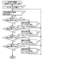
まず、図13のフローチャートを説明する。
レリーズが半押しされると(第1レリーズSW3がON処理されると)、モニタリングの停止処理(ステップS131)、AE(測光、測光演算など)処理(ステップS132)を行った後で、AF合焦ポイント検出のために、フォーカスレンズを所定ステップで動かし焦点評価値を取得するAF(スキャン処理)を実施する(ステップS133)。
First, the flowchart of FIG. 13 will be described.
When the release is half-pressed (when the first release SW 3 is turned on), after performing the monitoring stop process (step S131) and the AE (photometry, photometry calculation, etc.) process (step S132), AF In order to detect the focal point, AF (scanning process) is performed in which the focus lens is moved in predetermined steps to obtain a focus evaluation value (step S133).
焦点評価値(各ポイントでの画像信号の高周波成分に関するデータ)のピーク値(極大値)の高さとその時のレンズ位置を評価し、所定アルゴにて、カメラとしての合焦ポイントを決定する(ステップS134)。所定アルゴは、ここでは所定値以上でかつ一番近いもの<スキャン時の繰り出し量にて近いか遠いか判断可能>と設定するものとする。この部分のアルゴは、本発明の本質とは関係がないので種々の変更が可能であり、例えば一番評価値の高い極大値を合焦ポイントとするなどしてもよい。 The height of the peak value (maximum value) of the focus evaluation value (data relating to the high-frequency component of the image signal at each point) and the lens position at that time are evaluated, and a focusing point as a camera is determined by a predetermined algorithm (step) S134). Here, it is assumed that the predetermined algo is set to a value that is equal to or greater than a predetermined value and that is closest to <it is possible to determine whether the feed amount during scanning is close or far>. Since this part of the algo is not related to the essence of the present invention, various modifications are possible. For example, the maximum value with the highest evaluation value may be used as the in-focus point.
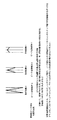
ここで決定した合焦ポイントの焦点評価値のピーク形状(ピーク尖鋭度)を検定(評価)する(ステップS135)。検定方法としては、合焦ポイント前後のフォーカス位置と、合焦ポイントにおける評価値の差を3段階にて算出することで、合焦ポイント近辺の傾きを求める方法である。ここでは、傾きのX成分となる合焦ポイント前後のステップ数の差は同じである(等間隔でスキャンするシステムの場合)ので、実質的には、評価値の差を適当な数値で割ることで評価値差を3段階に丸めることとなる。算出する傾きは、片側のみでもよいし、両側で算出して平均するやり方でもよい(図12のピーク値形状概念図参照)。 The peak shape (peak sharpness) of the focus evaluation value of the focus point determined here is tested (evaluated) (step S135). The verification method is a method for obtaining the inclination near the focus point by calculating the difference between the focus position before and after the focus point and the evaluation value at the focus point in three stages. Here, the difference in the number of steps before and after the in-focus point, which is the X component of the slope, is the same (in the case of a system that scans at equal intervals), so substantially the difference in evaluation value is divided by an appropriate value. The evaluation value difference is rounded to three stages. The slope to be calculated may be only on one side or may be calculated on both sides and averaged (see the peak value shape conceptual diagram in FIG. 12).
本実施例5では、評価値範囲が、0から1200程度と仮定し、3段階に丸めるために、評価値の差を300程度で割って尖鋭度を算出しているが、この具体的数値自体に意味はなく、種々の変更が可能である。 In the fifth embodiment, assuming that the evaluation value range is about 0 to 1200, the sharpness is calculated by dividing the difference between the evaluation values by about 300 in order to round to three stages. There is no meaning and various modifications are possible.
〈1〉図12に示すピーク近傍傾き3(形状段階3)は、傾きが比較的急峻で、形状が尖鋭な場合を示しており、決定された合焦ポイント部分が突出して高いため合焦ポイント検出がしやすく、信頼性が比較的高いことを意味する。 <1> The peak vicinity slope 3 (shape stage 3) shown in FIG. 12 shows a case where the slope is relatively steep and the shape is sharp, and the determined focus point portion protrudes and is high, so that the focus point. It means that it is easy to detect and relatively reliable.
〈2〉図12に示すピーク近傍傾き1(形状段階1)は傾きが比較的なだらかで、形状が幅広いことを示し、決定された合焦ポイントは、合焦位置選定としては問題がない(合焦閾値以上であるため合焦不能とする程低くはないが)が、合焦位置ピークが決めにくいため、価値が合焦閾値以下の部分となる可能性がある(信頼性が比較的低くなる可能性がある)ことを意味する。 <2> Peak vicinity slope 1 (shape stage 1) shown in FIG. 12 indicates that the slope is relatively gentle and the shape is wide, and the determined focus point has no problem as a focus position selection (focus position). Although it is not low enough to make it impossible to focus because it is above the focus threshold), it is difficult to determine the focus position peak, so the value may be below the focus threshold (reliability is relatively low) It may be possible).
〈3〉図12に示すピーク近傍傾き2(形状段階2)は、傾きが標準的であり、決定された合焦ポイントの検出信頼性が通常レベルであることを意味する。 <3> The peak vicinity slope 2 (shape stage 2) shown in FIG. 12 means that the slope is standard and the detection reliability of the determined focus point is at a normal level.
本実施例5では、上記〈1〉〜〈3〉のどのレベルで有るかを判定した後、通常のフォーカスブラケット撮影枚数(標準枚数。ここでは3枚)を自動的に設定変更(増減する)(ステップS136)。この設定変更は、メモリ12のフォーカスブラケット撮影枚数設定メモリに予め記憶されている設定内容に基づいて行われる。
In the fifth embodiment, after determining which level of the above <1> to <3>, the normal focus bracket shooting number (standard number, here three) is automatically changed (increased or decreased). (Step S136). This setting change is performed based on the setting contents stored in advance in the focus bracket shooting number setting memory of the
すなわち、信頼性がきわめて高い上記〈1〉(ピーク尖鋭度>3:第1の所定値)のような場合には、合焦位置のみの撮影でも問題がないと考えられるので、撮影枚数を1枚にセットする。 That is, in the case of <1> (peak sharpness> 3: first predetermined value) with extremely high reliability, it can be considered that there is no problem in photographing only at the in-focus position. Set on a sheet.
逆に、信頼性が低い〈2〉(ピーク尖鋭度<1:第2の所定値)のような場合には、撮影枚数を2枚増やして5枚にセットし、合焦の確率を自動的に増やす制御とする。 Conversely, if the reliability is low, such as <2> (peak sharpness <1: second predetermined value), the number of shots is increased by 2 and set to 5 to automatically set the probability of focusing The control is increased to
標準的な〈3〉のような場合には、通常通りの撮影枚数(撮影枚数3枚セット)とする。 In the case of standard <3>, the number of shots is set as usual (a set of 3 shots).
なお、信頼性が高い場合にも、必ずしも1枚のみの撮影で撮影意図を反映できるとは限らない場合(コントラストの高い人物撮影において手前の目にきちんと合焦させたい様な場合など)には、フォーカス間隔を細かく取って、標準撮影枚数を5枚以上程度に設定して、そこから増減する構成としてもよいし、増減枚数を10枚などの大きい数値や、前後非対称に設定してもよい。ここでは、フローチャートが煩雑になり説明も冗長となるため、あえてシンプルな構成にて説明している。 Note that even if the reliability is high, it is not always possible to reflect the shooting intention by shooting only one image (such as when you want to focus properly on the front eye in high-contrast portrait shooting). The focus interval may be set finely, the standard number of shots may be set to about 5 or more, and the number of shots may be increased or decreased from there. . Here, since the flowchart is complicated and the description is redundant, the description is given with a simple configuration.
また、上記セット後、ステップS136において、フォーカスブラケットの現在枚数カウンタに1をセットする。なお、この現在枚数のセットは、以下のステップS137で行うようにしてもよい。 After the setting, in step S136, 1 is set in the current number counter of the focus bracket. Note that the setting of the current number of sheets may be performed in the following step S137.
以上のようにセットした後、所定のフォーカスブラケット間隔(ここでは、パルスモータ方式のフォーカス制御を想定しており、どのくらいのフォーカスステップ間隔にてフォーカスをずらして撮影するかを示している)を設定する(ステップS137)。ここでは、通常2ステップ間隔と設定するものとしている。この部分はカメラ構成(焦点距離やレンズ構成、レンズのF値や絞り値、必要とされるフォーカス精度などにより異なるが、2ステップに意味があるわけではなく、通常のフォーカスブラケットのフォーカス間隔をセットするという意味である。 After setting as described above, set a predetermined focus bracket interval (here, it is assumed that pulse motor focus control is used and shows how much focus step interval is used for shooting with the focus shifted) (Step S137). Here, the interval is usually set to 2 steps. This part varies depending on the camera configuration (focal length, lens configuration, lens F value and aperture value, required focus accuracy, etc., but the two steps are not meaningful, and the focus interval of the normal focus bracket is set. It means to do.
決定された合焦ポイントにフォーカスレンズをセット(駆動)する(ステップS138)。 The focus lens is set (driven) at the determined in-focus point (step S138).
なお、図13のステップS138の後、レリーズが押し込んで全押しされた後(第2レリーズSW4がON処理された後)の動作は、図6をそのまま適用できるので、ここでの説明は省略する。 Note that, after step S138 of FIG. 13 and after the release is pushed in and fully pressed (after the second release SW4 is turned on), FIG. 6 can be applied as it is, and the description thereof is omitted here. .
図13のレリーズ半押し動作の部分で述べたように、ここに設定した枚数はあくまでも説明を簡略化するために標準枚数を減らした事例であり、信頼性の高い合焦ポイントの場合でも例えば3枚以上の撮影を行えるように構成するのが撮影者の意図する部分にきちんとフォーカスを合わせるというフォーカスブラケットモード本来の意図には合致しているので、そのように構成しても良いし、評価値と撮影枚数の設定段階数も3段階でなく多段階に構成しても良い。 As described in the part of the release half-press operation in FIG. 13, the number of sheets set here is an example in which the standard number is reduced for the sake of simplification of explanation, and even in the case of a highly reliable focus point, for example, 3 Since it is configured to be able to take more than one shot, it matches the original intention of the focus bracket mode, which is to properly focus on the part intended by the photographer. The number of steps for setting the number of shots may be configured in multiple stages instead of three.
以上の実施例により、AF合焦ポイントの信頼性に応じて自動的に撮影枚数を増減することで、原理的に合様可能性(信頼性)が比較的高い場合には撮影枚数を削減して無駄な撮影を防止し、合焦可能性(信頼性)が比較的低い場合には撮影枚数を増やして、より合焦が得られる確率を増やすことができるインテリジェントな撮像装置の合焦機構とすることができる。 According to the above embodiment, the number of shots is automatically increased / decreased according to the reliability of the AF in-focus point, thereby reducing the number of shots in principle when the possibility of matching (reliability) is relatively high. An intelligent imaging device focusing mechanism that can prevent unnecessary shooting and increase the number of shots when the focusability (reliability) is relatively low, thereby increasing the probability of achieving more focus. can do.
また、コスト面でも全て制御装置内での処理追加にて構成できるため、コストアップすることがなく、安価に構成することが可能である。 Further, since all can be configured by adding processing within the control device in terms of cost, it is possible to configure at low cost without increasing the cost.
実施例6は、フォーカス間隔設定を変更する実施例である。フォーカスブラケットを行うことは事前に設定されているものとする。 In the sixth embodiment, the focus interval setting is changed. It is assumed that the focus bracketing is performed in advance.
まず、図14のフローチャートを説明する。
レリーズが半押しされると(第1レリーズSW3がON処理されると)、モニタリングの停止処理(ステップS141)、AE(測光、測光演算など)処理(ステップS142)を行った後で、AF合焦ポイント検出のために、フォーカスレンズを所定ステップで動かし焦点評価値を取得するAF(スキャン処理)を実施する(ステップS143)。
First, the flowchart of FIG. 14 will be described.
When the release is half-pressed (when the first release SW3 is turned ON), after the monitoring stop process (step S141) and the AE (photometry, photometry calculation, etc.) process (step S142) are performed, AF In order to detect the focal point, AF (scanning process) is performed in which the focus lens is moved in predetermined steps to acquire a focus evaluation value (step S143).
焦点評価値(各ポイントでの画像信号の高周波成分に関するデータ)のピーク値(極大値)の高さとその時のレンズ位置を評価し、所定アルゴにて、カメラとしての合焦ポイントを決定する(ステップS144)。所定アルゴは、ここでは所定値以上でかつ一番近いもの<スキャン時の繰り出し量にて近いか遠いか判断可能>と設定するものとする。この部分のアルゴは、本発明の本質とは関係がないので種々の変更が可能であり、例えば一番評価値の高い極大値を合焦ポイントとするなどしてもよい。 The height of the peak value (maximum value) of the focus evaluation value (data relating to the high-frequency component of the image signal at each point) and the lens position at that time are evaluated, and a focusing point as a camera is determined by a predetermined algorithm (step) S144). Here, it is assumed that the predetermined algo is set to a value that is equal to or greater than a predetermined value and that is closest to <it is possible to determine whether the feed amount during scanning is close or far>. Since this part of the algo is not related to the essence of the present invention, various modifications are possible. For example, the maximum value with the highest evaluation value may be used as the in-focus point.
ここで決定した合焦ポイントの焦点評価値のピーク形状(ピーク尖鋭度)を検定(評価)する(ステップS145)。検定方法としては、合焦ポイント前後のフォーカス位置と、合焦ポイントにおける評価値の差を3段階にて算出することで、合焦ポイント近辺の傾きを求める方法である。ここでは、傾きのX成分となる合焦ポイント前後のステップ数の差は同じである(等間隔でスキャンするシステムの場合)ので、実質的には、評価値の差を適当な数値で割ることで評価値差を3段階に丸めることとなる。算出する傾きは、片側のみでもよいし、両側で算出して平均するやり方でもよい(図12のピーク値形状概念図参照)。 The peak shape (peak sharpness) of the focus evaluation value of the focus point determined here is tested (evaluated) (step S145). The verification method is a method for obtaining the inclination near the focus point by calculating the difference between the focus position before and after the focus point and the evaluation value at the focus point in three stages. Here, the difference in the number of steps before and after the in-focus point, which is the X component of the slope, is the same (in the case of a system that scans at equal intervals), so substantially the difference in evaluation value is divided by an appropriate value. The evaluation value difference is rounded to three stages. The slope to be calculated may be only on one side or may be calculated on both sides and averaged (see the peak value shape conceptual diagram in FIG. 12).
本実施例6では、評価値範囲が、0から1200程度と仮定し、3段階に丸めるために、評価値の差を300程度で割って尖鋭度を算出しているが、この具体的数値自体に意味はなく、種々の変更が可能である。 In the sixth embodiment, it is assumed that the evaluation value range is about 0 to 1200, and the sharpness is calculated by dividing the difference between the evaluation values by about 300 in order to round to three stages. There is no meaning and various modifications are possible.
〈1〉図12に示すピーク近傍傾き3(形状段階3)は、傾きが比較的急峻で、形状が尖鋭な場合を示しており、決定された合焦ポイント部分が突出して高いため合焦ポイント検出がしやすく、信頼性が比較的高いことを意味する。 <1> The peak vicinity slope 3 (shape stage 3) shown in FIG. 12 shows a case where the slope is relatively steep and the shape is sharp, and the determined focus point portion protrudes and is high, so that the focus point. It means that it is easy to detect and relatively reliable.
〈2〉図12に示すピーク近傍傾き1(形状段階1)は傾きが比較的なだらかで、形状が幅広いことを示し、決定された合焦ポイントは、合焦位置選定としては問題がない(合焦閾値以上であるため合焦不能とする程低くはないが)が、合焦位置ピークが決めにくいため、価値が合焦閾値以下の部分となる可能性がある(信頼性が比較的低くなる可能性がある)ことを意味する。 <2> Peak vicinity slope 1 (shape stage 1) shown in FIG. 12 indicates that the slope is relatively gentle and the shape is wide, and the determined focus point has no problem as a focus position selection (focus position). Although it is not low enough to make it impossible to focus because it is above the focus threshold), it is difficult to determine the focus position peak, so the value may be below the focus threshold (reliability is relatively low) It may be possible).
〈3〉図12に示すピーク近傍傾き2(形状段階2)は、傾きが標準的であり、決定された合焦ポイントの検出信頼性が通常レベルであることを意味する。 <3> The peak vicinity slope 2 (shape stage 2) shown in FIG. 12 means that the slope is standard and the detection reliability of the determined focus point is at a normal level.
本実施例6では、上記〈1〉〜〈3〉のどのレベルで有るかを判定した後、通常のフォーカスブラケット撮影のフォーカス間隔(2step)を自動的に設定変更(増減する)(ステップS146)。この設定変更は、メモリ12のフォーカスブラケット駆動幅設定メモリに予め記憶されている設定内容に基づいて行われる。
In the sixth embodiment, after determining which level of <1> to <3>, the focus interval (2 steps) for normal focus bracket shooting is automatically changed (increased or decreased) (step S146). . This setting change is performed based on the setting contents stored in advance in the focus bracket drive width setting memory of the
すなわち、信頼性がきわめて高い上記〈1〉(ピーク尖鋭度>3:第1の所定値)のような場合には、フォーカス間隔を小さく(1stepに)設定し、決定合焦ポイントのごく近傍前後のみの撮影とする。 That is, in the case of <1> (peak sharpness> 3: first predetermined value) with extremely high reliability, the focus interval is set small (in one step), and is very close to the determined in-focus point. Only shooting.
逆に、信頼性が低い〈2〉(ピーク尖鋭度<1:第2の所定値)のような場合には、フォーカス間隔を通常より広く(3stepに)設定し、合焦できる確率をできるだけ増やす制御とする。 Conversely, in the case of <2> where the reliability is low (peak sharpness <1: second predetermined value), the focus interval is set wider than usual (in 3 steps) to increase the probability of focusing as much as possible. Control.
標準的な〈3〉のような場合には、通常通りのフォーカス間隔(2stepに)設定するものとする。 In the case of standard <3>, the normal focus interval (2 steps) is set.
信頼性が高い場合の設定で、フォーカス間隔が細かいので前後の設定枚数のみの撮影で撮影意図を反映できるとは限らない場合(コントラストの高い人物撮影において手前の目にきちんと合焦させたい様な場合など)には、撮影枚数を同時に増やす構成(トータルの振り幅を一定とする)構成や、撮影枚数も同時に減らす構成(無駄な撮影はできるだけしない)構成としてもよい。逆に焦点評価値が低い場合には、同時に枚数を増やす構成(+10枚など)とし、さらに厳密に合焦できる確率を増やしても良い、撮影枚数は減らす(トータルの振り幅は一定とする)構成としてもよいし、それらの組み合わせ構成としても良い。フローチャートが煩雑になり説明も冗長となるため、あえてシンプルな構成(フォーカスブラケット撮影枚数は5枚で固定)にて説明している。 This is a setting with high reliability, and the focus interval is fine, so it is not always possible to reflect the intention of shooting by shooting only the set number of frames before and after (such as when you want to focus properly on the front eye when shooting a high-contrast person In other cases, a configuration in which the number of shots is increased at the same time (the total swing is constant), or a configuration in which the number of shots is also reduced at the same time (unnecessary shooting is performed as little as possible) may be employed. Conversely, when the focus evaluation value is low, the number of images can be increased at the same time (such as +10), and the probability of focusing more precisely can be increased. The number of shots can be reduced (the total swing is constant). It is good also as a structure and it is good also as those combined structure. Since the flowchart is complicated and the description is redundant, the description is made with a simple configuration (the number of focus brackets is fixed at 5).
その後、所定のフォーカスブラケット枚を設定する(ステップS147)。ここでは、実施例5のように、標準枚数を5枚に設定するものとしている。なお、この部分は、カメラ構成(焦点距離やレンズ構成、レンズのF値や絞り値、必要とされるフォーカス精度など)により異なるが、5枚撮影に意味があるわけではなく、通常のフォーカスブラケットの撮影枚数をセットするという意味である。 Thereafter, a predetermined focus bracket sheet is set (step S147). Here, as in the fifth embodiment, the standard number is set to five. Note that this part varies depending on the camera configuration (focal length, lens configuration, lens F-number and aperture value, required focus accuracy, etc.), but it does not make sense for five-frame shooting. This means that the number of shots is set.
次に、フォーカスブラケットの現在枚数カウンタに1をセットし(ステップS147)、決定された合焦ポイントにフォーカスレンズをセット(駆動)する(ステップS148)。 Next, 1 is set in the current number counter of the focus bracket (step S147), and the focus lens is set (driven) at the determined focus point (step S148).
なお、図14のステップS148の後、レリーズが押し込んで全押しされた後(第2レリーズSW4がON処理された後)の動作は、図8をそのまま適用できるので、ここでの説明は省略する。 Note that, after step S148 of FIG. 14 and after the release is pushed in and fully pressed (after the second release SW4 is turned on), FIG. 8 can be applied as it is, and the description thereof is omitted here. .
図14のレリーズ半押し動作の部分で述べたように、ここに設定したフォーカス間隔はあくまでも説明を簡略化するために、適当なフォーカス間隔にて説明しており、フォーカス間隔ステップ数自体に意味はない。また、所定撮影枚数もフローを簡略化するため少なめに設定してあり、信頼性の高い合焦ポイントの場合でも5枚以上の撮影を行えるように構成し、撮影者の意図する部分に完全にきちんとフォーカスを合わせるという新たなフォーカスブラケットモードの意図に合致するように構成しても良い。撮像素子読み出し速度や、画像処理速度の高速化などもこの構成の追い風となる。評価値とフォーカス間隔の設定段階数も3段階でなく多段階に構成しても良い。 As described in the release half-press operation part of FIG. 14, the focus interval set here is explained with an appropriate focus interval for the sake of simplicity, and the meaning of the number of focus interval steps is itself. Absent. In addition, the predetermined number of shots is set to a small number to simplify the flow, and it is configured so that five or more shots can be taken even in the case of a highly reliable focus point. You may comprise so that it may match the intention of the new focus bracket mode of adjusting a focus properly. An imaging element reading speed and an increase in image processing speed also serve as a tailwind of this configuration. The number of stages for setting the evaluation value and the focus interval may be configured in multiple stages instead of three.
以上の実施例により、AF合焦ポイントの信頼性に応じて自動的にフォーカスブラケット時のフォーカス間隔を増減することで、原理的に合様可能性(信頼性)が比較的高い場合にはフォーカス間隔を狭くしてよりシビアに合焦ポイント近傍の画像を取得し、合焦可能性(信頼性)が比較的低い場合にはフォーカス間隔を広くして、より合焦が得られる確率を増やすことができるインテリジェントな撮像装置の合焦機構とすることができる。 According to the above embodiment, the focus interval at the time of the focus bracket is automatically increased or decreased according to the reliability of the AF in-focus point. Narrow the interval to acquire images near the in-focus point more severely, and if the focus possibility (reliability) is relatively low, widen the focus interval to increase the probability of obtaining more in-focus. It is possible to provide a focusing mechanism for an intelligent image pickup apparatus capable of
また、コスト面でも全て制御装置内での処理追加にて構成できるため、コストアップすることがなく、安価に構成することが可能である。 Further, since all can be configured by adding processing within the control device in terms of cost, it is possible to configure at low cost without increasing the cost.
実施例6のフローチャートである図14では、事前に合焦ポイントや、合焦領域を指定する場合である(フォーカスブラケットを行うことは事前に設定されているものとする)。合焦ポイントや合焦領域事前指定方法は本発明の本質では無いため、ここでの詳細な説明は控えるが、一般的な方法としては、タッチパネルにより撮影予定範囲をモニタリングしている時に、合焦したい任意の所定領域や、所定被写体、エッジなどをタッチして指定する方式や、あらかじめ合焦が可能な領域をモニタに表示しておき、それをSW操作やメニュー操作により選択する方式などがある。また、顔認識などにて発見された複数の顔をモニタに表示し、合焦したい顔をSWやタッチパネルにより選択する方法などもある。将来的には、被写体領域をカメラにて自動分割し、領域表示した上で、合焦したい領域をSWやタッチパネルにて選択させる方式も考えられる。以上何れかの方法により、事前に合焦させたい領域が指定されているものとする。 In FIG. 14, which is a flowchart of the sixth embodiment, a focus point and a focus area are designated in advance (assuming that the focus bracketing is set in advance). Since the focus point and focus area prior designation method are not the essence of the present invention, a detailed description thereof will be omitted. However, as a general method, the focus is adjusted when the scheduled shooting range is monitored by the touch panel. There are a method of touching and specifying an arbitrary predetermined area to be desired, a predetermined subject, an edge, and the like, a method of displaying a focusable area in advance on a monitor, and selecting it by SW operation or menu operation, etc. . There is also a method of displaying a plurality of faces found by face recognition on a monitor and selecting a face to be focused by SW or a touch panel. In the future, there may be a method in which the subject area is automatically divided by the camera, the area is displayed, and the area to be focused is selected by the SW or the touch panel. It is assumed that the region to be focused is designated in advance by any of the above methods.
まず、図15のフローチャートを説明する。フォーカスブラケットを行うことは事前に設定されているものとする。
レリーズが半押しされると(第1レリーズSW3がON処理されると)、モニタリングの停止処理(ステップS151)、AE(測光、測光演算など)処理(ステップS152)を行った後で、AF合焦ポイント検出のために、フォーカスレンズを所定ステップで動かし焦点評価値を取得するAF(スキャン処理)を実施する(ステップS153)。
First, the flowchart of FIG. 15 will be described. It is assumed that the focus bracketing is performed in advance.
When the release is half-pressed (when the first release SW3 is turned on), after the monitoring stop process (step S151) and the AE (photometry, photometry calculation, etc.) process (step S152) are performed, AF In order to detect the focal point, AF (scanning process) is performed in which the focus lens is moved in predetermined steps to acquire a focus evaluation value (step S153).
ここで、ステップS153は、ステップS153a〜S153cからなる。ステップS152のAE処理の後、事前に焦点評価値取得領域が指定されているか否かを判断し(ステップS153a)、指定が有る場合(ステップS153a/YES)、指定領域のみに対して、AF(スキャン処理)を行い(ステップS153c)、指定が無い場合(ステップS153a/NO)、全領域に対してAF(スキャン処理)を行う(ステップS153b)。つまり、本実施例7では、通常の場合(実施例5、6の場合)と異なり、焦点評価値取得領域は、指定された領域のみでの単数または複数の評価値の取得となり、合焦ポイントもその中から決定される。 Here, step S153 includes steps S153a to S153c. After the AE process of step S152, it is determined whether or not a focus evaluation value acquisition area is designated in advance (step S153a). If there is designation (step S153a / YES), AF ( Scan processing) is performed (step S153c), and if there is no designation (step S153a / NO), AF (scan processing) is performed on the entire area (step S153b). That is, in the seventh embodiment, unlike the normal case (in the case of the fifth and sixth embodiments), the focus evaluation value acquisition region is acquisition of one or a plurality of evaluation values only in the designated region, and the in-focus point. Is also determined from that.
以降のステップS154〜S158までの動作は、図14のステップS144〜S148と同じであるので、ここでの説明は省略する。 The subsequent operations from step S154 to S158 are the same as steps S144 to S148 in FIG.
また、図15のステップS158の後、レリーズが押し込んで全押しされた後(第2レリーズSW4がON処理された後)の動作は、図8をそのまま適用できるので、ここでの説明は省略する。 Also, after step S158 in FIG. 15 and after the release is pushed in and fully pressed (after the second release SW4 is turned on), FIG. 8 can be applied as it is, and the description thereof is omitted here. .
以上の実施例により、AF合焦ポイントの信頼性に応じて自動的にフォーカスブラケット時のフォーカス間隔を増減することで、原理的に合様可能性(信頼性)が比較的高い場合にはフォーカス間隔を狭くしてよりシビアに合焦ポイント近傍の画像を取得し、合焦可能性(信頼性)が比較的低い場合にはフォーカス間隔を広くして、より合焦が得られる確率を増やすことができるインテリジェントな撮像装置の合焦機構とすることができる。 According to the above embodiment, the focus interval at the time of the focus bracket is automatically increased or decreased according to the reliability of the AF in-focus point. Narrow the interval to acquire images near the in-focus point more severely, and if the focus possibility (reliability) is relatively low, widen the focus interval to increase the probability of obtaining more in-focus. It is possible to provide a focusing mechanism for an intelligent image pickup apparatus capable of
また、コスト面でも全て制御装置内での処理追加にて構成できるため、コストアップすることがなく、安価に構成することが可能である。 Further, since all can be configured by adding processing within the control device in terms of cost, it is possible to configure at low cost without increasing the cost.
なお、実施例7では、説明簡略化するためにフォーカス間隔を増減するタイプ(実施例6のタイプ)にて説明したが、実施例5との組み合わせ(撮影枚数を変更する実施例)との組み合わせ(この場合、図15のステップS154〜S158までの動作を、図13のステップS134〜S138と置き換え、図15のステップS158以降は、図8をそのまま適用する)や、それらの組み合わせでももちろん実施可能であり、事前に決めた合焦範囲内にてAFスキャンを行い、合焦ポイントの焦点評価値の大きさに応じて、フォーカスブラケットの撮影枚数や、フォーカス間隔を変更する点は同じである。 In the seventh embodiment, the type of increasing / decreasing the focus interval (the type of the sixth embodiment) has been described in order to simplify the description, but the combination with the fifth embodiment (the embodiment in which the number of shots is changed) is combined. (In this case, the operations from step S154 to S158 in FIG. 15 are replaced with steps S134 to S138 in FIG. 13, and FIG. 8 is applied as it is after step S158 in FIG. 15). This is the same in that AF scanning is performed within a predetermined in-focus range, and the number of focus bracket shots and the focus interval are changed in accordance with the focus evaluation value of the in-focus point.
実施例8は、実施例5において、新たに設定された、撮影枚数やフォーカスブラケット間隔を表示手段(図1の表示装置7。例えば、LCDモニタ、有機EL、LED等)に表示する実施例である。
The eighth embodiment is an embodiment in which the number of shots and the focus bracket interval newly set in the fifth embodiment are displayed on the display means (the
まず、図16のフローチャートを説明する。本実施例8においても、フォーカスブラケットを行うことは事前に設定されているものとする。
レリーズが半押しされた後(第1レリーズSW3がON処理された後)の動作であるステップS161〜S168は、実施例5における図13のステップS131〜S138と同じであるので、ここでの説明は省略する。
First, the flowchart of FIG. 16 will be described. Also in the eighth embodiment, the focus bracketing is set in advance.
Steps S161 to S168, which are operations after the release is half-pressed (after the first release SW3 is turned on), are the same as steps S131 to S138 of FIG. Is omitted.
ステップS168のセット後、新たに決定した撮影枚数とフォーカス間隔(ここでは規定間隔)をLCDモニタ上に表示する(ステップS169)。この表示により、ユーザに焦点評価値の信頼性や、今後の撮影動作枚数を予告することができ、カメラのホールディングなど(撮影枚数が増えればホールディング時間をあらかじめ長く予測し、しっかり構える必要がある)を改善することが可能であり、設定枚数や、フォーカス間隔に不満があれば撮影をやめることが可能となり、無駄な撮影を事前に防止することも可能となる。 After the setting in step S168, the newly determined number of shots and the focus interval (here, the specified interval) are displayed on the LCD monitor (step S169). With this display, the user can be notified of the reliability of the focus evaluation value and the number of future shots to be taken. Camera holding, etc. (If the number of shots increases, it is necessary to predict the holding time in advance and hold it firmly.) If the set number of sheets and the focus interval are unsatisfactory, it is possible to stop shooting and prevent unnecessary shooting in advance.
また、図16のステップS169の後、レリーズが押し込んで全押しされた後(第2レリーズSW4がON処理された後)の動作は、図11をそのまま適用できるので、ここでの説明は省略する。 Also, after step S169 in FIG. 16 and after the release is pushed in and fully pressed (after the second release SW4 is turned on), FIG. 11 can be applied as it is, and description thereof is omitted here. .
以上の実施例により、AF合焦ポイントの信頼性に応じて自動的に撮影枚数を増減することで、原理的に合様可能性(信頼性)が比較的高い場合には撮影枚数を削減して無駄な撮影を防止し、合焦可能性(信頼性)が比較的低い場合には撮影枚数を増やして、より合焦が得られる確率を増やすことができるインテリジェントな撮像装置の合焦機構とすることができる。 According to the above embodiment, the number of shots is automatically increased / decreased according to the reliability of the AF in-focus point, thereby reducing the number of shots in principle when the possibility of matching (reliability) is relatively high. An intelligent imaging device focusing mechanism that can prevent unnecessary shooting and increase the number of shots when the focusability (reliability) is relatively low, thereby increasing the probability of achieving more focus. can do.
また、コスト面でも全て制御装置内での処理追加にて構成できるため、コストアップすることがなく、安価に構成することが可能である。 Further, since all can be configured by adding processing within the control device in terms of cost, it is possible to configure at low cost without increasing the cost.
また、表示手段として、通常カメラに設けられているLCD、有機EL、LEDなどの各種モニタ手段を使用することでコストを追加することなく実現が可能である。 Further, it is possible to realize the display without adding cost by using various monitor means such as an LCD, an organic EL, and an LED provided in a normal camera as the display means.
なお、上記実施例8の説明では、実施例5を元にして説明したが、実施例6や実施例7との組み合わせでももちろん実施が可能であるし、表示する項目も、設定枚数だけでも良いし、フォーカス間隔だけでも良いし、初期値から変更されたものだけでも良いし、他の項目と一緒に表示してもよい。また、撮影枚数が多い場合などに、第1レリーズSW3作業中に三脚の使用を呼びかけたり、第2レリーズSW4作業中にしっかりホールドする旨呼びかけたりする表示などを追加して行う構成としても良い。 In the description of the eighth embodiment, the description has been made based on the fifth embodiment. However, the present invention can of course be implemented in combination with the sixth and seventh embodiments, and the items to be displayed may be only the set number. Then, only the focus interval may be used, or only the focus interval may be changed, or it may be displayed together with other items. In addition, when the number of shots is large, a configuration may be added in which a display that calls for the use of a tripod during the first release SW3 work or a call for holding firmly during the second release SW4 work is added.
また、上記実施例8の説明では、撮影枚数やフォーカスブラケットの間隔などを表示することにより、撮像装置のユーザに通知するものとしたが、音声発生手段等による音声発生により上記表示内容と同じ内容を通知するようにしてもよい。また、表示及び音声発生の両方で、上記内容を通知するようにしてもよい。 In the description of the eighth embodiment, the user of the imaging apparatus is notified by displaying the number of shots and the distance between the focus brackets. However, the same contents as the display contents described above are generated by the sound generation by the sound generation means. May be notified. Moreover, you may make it notify the said content by both a display and audio | voice generation | occurrence | production.
上記各実施例では、焦点評価値に応じて、撮影枚数やフォーカス間隔を変更する事例にて本発明を説明してきたが、焦点評価値と撮影距離に応じて、撮影枚数やフォーカス間隔を変更する実施例も考えられる。例えば、撮影距離が近い場合は、被写界深度が比較的浅い為フォーカス間隔を少し替えると大きく合焦が変化してしまう場合は、フォーカス間隔をより狭くして、撮影枚数は変化させない構成とすることを基本として、焦点評価値も加味してフォーカス間隔と撮影枚数を決める実施例とする。また撮影距離が遠い場合は、被写界深度が比較的深いためフォーカス間隔を広げて撮影枚数も増やすことを基本として、焦点評価値も加味して決定するなどが考えられる。また同様に撮影レンズの焦点距離や、絞り値を加味した構成も考えられる。 In each of the above embodiments, the present invention has been described with an example in which the number of shots and the focus interval are changed according to the focus evaluation value. However, the number of shots and the focus interval are changed according to the focus evaluation value and the shooting distance. Examples are also conceivable. For example, if the shooting distance is short, the depth of field is relatively shallow, so if the focus interval changes a little when the focus interval changes a little, the focus interval will be narrower and the number of shots will not change. In this embodiment, the focus interval and the number of shots are determined in consideration of the focus evaluation value. Also, when the shooting distance is long, the depth of field is relatively deep, so that the focus interval is increased and the number of shots is increased. Similarly, a configuration in which the focal length of the photographing lens and the aperture value are taken into consideration can be considered.
焦点距離が短い(広角レンズ)や絞り込んだ場合は、被写界深度が深いため、逆にフォーカス間隔を広くして、撮影枚数も増やすことを基本として、焦点評価値を加味して、撮影枚数やフォーカス間隔を設定し、焦点距離が長い場合や絞りを開けた場合はフォーカス間隔を狭くして、撮影枚数はそのままに設定することを基本として、焦点評価値を加味して撮影枚数やフォーカス間隔を加減し決定するなどの実施例も考えられる。さらにこれらの組み合わせの実施例も考えられるが、説明がきわめて複雑となるため、記述した実施例の組み合わせとして実施例とする。 When the focal length is short (wide-angle lens) or narrowed down, the depth of field is deep, so conversely, the focus interval is increased and the number of shots is increased. If the focal length is long or the aperture is opened, the focus interval is narrowed and the number of shots is set as it is. It is also possible to consider an embodiment in which the value is determined by adjusting. Further, examples of these combinations are also conceivable, but the description is extremely complicated, and therefore, examples are given as combinations of the described examples.
また、変更するパラメータを撮影枚数やフォーカス間隔ではなく、絞り値または絞り値との組み合わせとすることも考えられる。すなわち、焦点評価値が大きい場合は、絞りはそのままにし、小さい場合は絞りを絞り込むなどの実施例と組み合わせても良いし。焦点評価値が高い場合は、絞りをあけてよりボケ味を際だたせる方向とし、フォーカス間隔を細かく設定し、撮影枚数も有る程度確保するような構成なども考えられる。 It is also conceivable that the parameter to be changed is not the number of shots or the focus interval but an aperture value or a combination of aperture values. That is, when the focus evaluation value is large, the diaphragm may be left as it is, and when the focus evaluation value is small, the diaphragm may be narrowed. In the case where the focus evaluation value is high, a configuration in which the aperture is widened to make the blur more prominent, the focus interval is set finely, and a certain number of shots is secured is also conceivable.
以上、本発明の各実施例について説明したが、上記各実施例の記載に限定されるものではなく、その要旨を逸脱しない範囲において種々の変形が可能である。すなわち、本発明は、合焦ポイントに決定した焦点評価値の大きさにより、撮影枚数、フォーカス間隔、絞り値などを変更することで、よりインテリジェントなフォーカスブラケット撮影を行うためのものであり、種々の変形実施が可能であり、コストは最小限で、省エネ、省資源にも貢献する。 As mentioned above, although each Example of this invention was described, it is not limited to description of each said Example, A various deformation | transformation is possible in the range which does not deviate from the summary. That is, the present invention is for performing more intelligent focus bracket shooting by changing the number of shots, the focus interval, the aperture value, and the like according to the magnitude of the focus evaluation value determined as the focus point. Can be implemented, and the cost is minimal, contributing to energy and resource savings.
また、ピーク形状の検定方法は、本発明の本質部分ではなく、一例として述べてきたやり方(ピーク前後の傾きから求める方式)の他にも、逆に単位評価値あたりの、フォーカスレンズステップ幅から基準値を算出してもよいし、AFスキャン時のレンズステップデータまたはレンズステップデータから算出した概略撮影距離関連データと、評価値データとの関係式から演算で求める方式や、グラフプロットしてパターンマッチングで検定する方式、ピーク前後のベクトルデータから求める方式など、種々の方式を採用してもよい。 Further, the peak shape verification method is not an essential part of the present invention, and in addition to the method described as an example (a method obtained from the inclination before and after the peak), conversely, from the focus lens step width per unit evaluation value. The reference value may be calculated, the lens step data at the time of AF scanning, or the method for calculating from the relational expression between the approximate shooting distance-related data calculated from the lens step data and the evaluation value data, or the pattern by plotting the graph Various methods such as a method of checking by matching and a method of obtaining from vector data before and after the peak may be adopted.
また、上述した各実施例における撮像装置における制御動作は、ハードウェア、または、ソフトウェア、あるいは、両者の複合構成によって実行することも可能である。なお、ソフトウェアによる処理を実行する場合には、処理シーケンスを記録したプログラムを、専用のハードウェアに組み込まれているコンピュータ内のメモリにインストールして実行させるか、あるいは、各種処理が実行可能な汎用コンピュータにプログラムをインストールして実行させることが可能である。例えば、プログラムは、記録媒体としてのハードディスクやROM(Read Only Memory)に予め記録しておくことが可能である。あるいは、プログラムは、フロッピー(登録商標)ディスク、CD−ROM(Compact Disc Read Only Memory),MO(Magneto optical)ディスク,DVD(Digital Versatile Disc)、磁気ディスク、半導体メモリなどのリムーバブル記録媒体に、一時的、あるいは、永続的に格納(記録)しておくことが可能である。このようなリムーバブル記録媒体は、いわゆるパッケージソフトウエアとして提供することが可能である。なお、プログラムは、上述したようなリムーバブル記録媒体からコンピュータにインストールする他、ダウンロードサイトから、コンピュータに無線転送したり、LAN(Local Area Network)、インターネットといったネットワークを介して、コンピュータに有線で転送したりし、コンピュータでは、転送されてきたプログラムを受信し、内蔵するハードディスク等の記録媒体にインストールすることが可能である。 Further, the control operation in the image pickup apparatus in each embodiment described above can be executed by hardware, software, or a combined configuration of both. In addition, when executing processing by software, a program in which a processing sequence is recorded is installed in a memory in a computer incorporated in dedicated hardware and executed, or a general-purpose capable of executing various processing It is possible to install and execute a program on a computer. For example, the program can be recorded in advance on a hard disk or a ROM (Read Only Memory) as a recording medium. Alternatively, the program is temporarily stored on a removable recording medium such as a floppy (registered trademark) disk, a CD-ROM (Compact Disc Read Only Memory), an MO (Magneto optical) disk, a DVD (Digital Versatile Disc), a magnetic disk, or a semiconductor memory. Or can be stored (recorded) permanently. Such a removable recording medium can be provided as so-called package software. The program is installed on the computer from the removable recording medium as described above, or is wirelessly transferred from the download site to the computer, or is wired to the computer via a network such as a LAN (Local Area Network) or the Internet. On the other hand, the computer can receive the transferred program and install it on a recording medium such as a built-in hard disk.
また、上記各実施例で説明した処理動作に従って時系列的に実行されるのみならず、処理を実行する装置の処理能力、あるいは、必要に応じて並列的にあるいは個別に実行するように構築することも可能である。 Further, not only is the processing performed in time series according to the processing operations described in the above embodiments, but also the processing capability of the apparatus that executes the processing, or a configuration that is executed in parallel or individually as necessary. It is also possible.
以上の各実施例の説明から分かるように、本発明の撮像装置によれば、メインの効果(合焦部信頼性に応じた自動枚数設定、フォーカス間隔設定により煩雑な手順がなくブラケット撮影が行える)の他に、無駄な撮影防止や、撮影意図を外れた画像群を保存してしまうことがない。よって、省エネ、省資源の効果がある。 As can be seen from the description of each of the above embodiments, according to the imaging apparatus of the present invention, the main effect (automatic number setting according to the in-focus portion reliability and focus interval setting can be used to perform bracket shooting without complicated procedures. In addition to the above, there is no need to prevent useless shooting or to save an image group that is not intended for shooting. Therefore, there is an effect of energy saving and resource saving.
また、本発明の撮像装置によれば、設定結果を表示することで、カメラの自動設定結果に不満が有る場合は、レリーズ操作やモード設定をやり直すことができるため、前述の追加効果を更に強化することができる。 Further, according to the imaging apparatus of the present invention, when the setting result is displayed and the automatic setting result of the camera is unsatisfactory, the release operation and the mode setting can be performed again. can do.
また、本発明の撮像装置によれば、操作性の観点でも、すべて自動的に判断し、設定、撮影、保存が行われるので撮影者の力量に関わらず、理論的裏付けに基づく撮影を自動的に行うことができる。 In addition, according to the imaging apparatus of the present invention, from the viewpoint of operability, all judgments are automatically made, and setting, photographing, and storage are performed. Therefore, photographing based on theoretical support is automatically performed regardless of the ability of the photographer. Can be done.
本発明は、撮像装置のフォーカス機構に適用できる。応用例として、撮像機能付き携帯機器のフォーカス機構に適用できる。 The present invention can be applied to a focus mechanism of an imaging apparatus. As an application example, it can be applied to a focus mechanism of a portable device with an imaging function.
1 制御装置(CPU)
2 測光センサ
3 第1レリーズSW
4 第2レリーズSW
5 フォーカス駆動装置
6 シャッタ駆動装置
7 表示装置
8 撮像素子(撮像光学系、電気的撮像手段)
9 記憶手段
10 演算手段
11 時間カウント手段(タイマ手段)
12 メモリ
1 Control device (CPU)
2 Photometric sensor 3 First release SW
4 Second release SW
DESCRIPTION OF SYMBOLS 5 Focus drive device 6
9 Storage means 10 Calculation means 11 Time counting means (timer means)
12 memory
Claims (3)
電気的撮像手段と、
撮影に先立ち、フォーカス位置を変化させながら撮像画面内の複数箇所の画像信号を取得し、コントラスト成分に応じた焦点評価値を取得する焦点評価値取得手段と、を有し、
前記焦点評価値取得手段で取得した焦点評価値の大きさに応じて、フォーカスブラケットのフォーカス間隔を自動的に変更する撮像装置において、
前記焦点評価値取得手段で取得した焦点評価値の大きさが、第1の所定値以上の場合には、前記フォーカスブラケットのフォーカス間隔を所定間隔より小さくし、第2の所定値より小さい場合には、前記フォーカスブラケットのフォーカス間隔を所定間隔より大きくすることを特徴とする撮像装置。 An imaging optical system;
Electrical imaging means;
Focus evaluation value acquisition means for acquiring image evaluation signals of a plurality of locations in the imaging screen while changing the focus position prior to shooting, and acquiring a focus evaluation value according to a contrast component,
In the imaging device that automatically changes the focus interval of the focus bracket according to the size of the focus evaluation value acquired by the focus evaluation value acquisition unit,
When the focus evaluation value acquired by the focus evaluation value acquisition means is greater than or equal to a first predetermined value, the focus interval of the focus bracket is made smaller than a predetermined interval and smaller than a second predetermined value. The imaging apparatus is characterized in that a focus interval of the focus bracket is made larger than a predetermined interval.
電気的撮像手段と、
ピントを合わせたい領域又はポイントを事前に指定する主要被写体指定手段と、
前記主要被写体指定手段で指定された領域又はポイントから所定範囲に関し、フォーカス位置を変化させながら画像信号を取得し、コントラスト成分に応じた焦点評価値を取得する焦点評価値取得手段と、を有し、
前記焦点評価値取得手段で取得した焦点評価値の大きさに応じて、フォーカスブラケットのフォーカス間隔を自動的に変更する撮像装置において、
前記焦点評価値取得手段で取得した焦点評価値の大きさが、第1の所定値以上の場合には、前記フォーカスブラケットのフォーカス間隔を所定値より小さくし、第2の所定値より小さい場合には、前記フォーカスブラケットのフォーカス間隔を所定値より大きくすることを特徴とする撮像装置。 An imaging optical system;
Electrical imaging means;
A main subject specifying means for specifying in advance the area or point to be focused;
A focus evaluation value acquiring unit that acquires an image signal while changing a focus position with respect to a predetermined range from an area or a point specified by the main subject specifying unit, and acquires a focus evaluation value according to a contrast component; ,
In the imaging device that automatically changes the focus interval of the focus bracket according to the size of the focus evaluation value acquired by the focus evaluation value acquisition unit,
When the magnitude of the focus evaluation value acquired by the focus evaluation value acquisition means is greater than or equal to the first predetermined value, the focus interval of the focus bracket is made smaller than the predetermined value and smaller than the second predetermined value. The imaging apparatus is characterized in that a focus interval of the focus bracket is made larger than a predetermined value.
Priority Applications (1)
| Application Number | Priority Date | Filing Date | Title |
|---|---|---|---|
| JP2012002176A JP5278564B2 (en) | 2007-06-20 | 2012-01-10 | Imaging device |
Applications Claiming Priority (3)
| Application Number | Priority Date | Filing Date | Title |
|---|---|---|---|
| JP2007162469 | 2007-06-20 | ||
| JP2007162469 | 2007-06-20 | ||
| JP2012002176A JP5278564B2 (en) | 2007-06-20 | 2012-01-10 | Imaging device |
Related Parent Applications (1)
| Application Number | Title | Priority Date | Filing Date |
|---|---|---|---|
| JP2011179750A Division JP4907740B2 (en) | 2007-06-20 | 2011-08-19 | Imaging device |
Publications (2)
| Publication Number | Publication Date |
|---|---|
| JP2012103722A JP2012103722A (en) | 2012-05-31 |
| JP5278564B2 true JP5278564B2 (en) | 2013-09-04 |
Family
ID=40398650
Family Applications (3)
| Application Number | Title | Priority Date | Filing Date |
|---|---|---|---|
| JP2007182147A Expired - Fee Related JP4890370B2 (en) | 2007-06-20 | 2007-07-11 | Imaging device |
| JP2011179750A Expired - Fee Related JP4907740B2 (en) | 2007-06-20 | 2011-08-19 | Imaging device |
| JP2012002176A Expired - Fee Related JP5278564B2 (en) | 2007-06-20 | 2012-01-10 | Imaging device |
Family Applications Before (2)
| Application Number | Title | Priority Date | Filing Date |
|---|---|---|---|
| JP2007182147A Expired - Fee Related JP4890370B2 (en) | 2007-06-20 | 2007-07-11 | Imaging device |
| JP2011179750A Expired - Fee Related JP4907740B2 (en) | 2007-06-20 | 2011-08-19 | Imaging device |
Country Status (1)
| Country | Link |
|---|---|
| JP (3) | JP4890370B2 (en) |
Cited By (1)
| Publication number | Priority date | Publication date | Assignee | Title |
|---|---|---|---|---|
| US11212433B2 (en) | 2018-07-02 | 2021-12-28 | Canon Kabushiki Kaisha | Image capture apparatus and control method thereof |
Families Citing this family (10)
| Publication number | Priority date | Publication date | Assignee | Title |
|---|---|---|---|---|
| JP5206494B2 (en) | 2009-02-27 | 2013-06-12 | 株式会社リコー | Imaging device, image display device, imaging method, image display method, and focus area frame position correction method |
| JP2014126596A (en) * | 2012-12-25 | 2014-07-07 | Samsung R&D Institute Japan Co Ltd | Imaging apparatus, imaging method, and imaging program |
| WO2014125682A1 (en) | 2013-02-14 | 2014-08-21 | 富士フイルム株式会社 | Image pickup device and focusing control method |
| JP5662511B2 (en) | 2013-04-10 | 2015-01-28 | シャープ株式会社 | Imaging device |
| JP6391304B2 (en) * | 2014-06-05 | 2018-09-19 | キヤノン株式会社 | Imaging apparatus, control method, and program |
| JP6487678B2 (en) * | 2014-11-21 | 2019-03-20 | キヤノン株式会社 | Focus detection apparatus and control method thereof |
| JP6575231B2 (en) * | 2015-08-26 | 2019-09-18 | カシオ計算機株式会社 | Imaging apparatus, imaging setting method, and program |
| WO2017061095A1 (en) * | 2015-10-06 | 2017-04-13 | パナソニックIpマネジメント株式会社 | Image capture device |
| JP6865395B2 (en) * | 2016-03-10 | 2021-04-28 | パナソニックIpマネジメント株式会社 | Imaging device |
| CN110419210B (en) | 2017-03-15 | 2021-01-12 | 富士胶片株式会社 | Image pickup device, image pickup method, and recording medium |
Family Cites Families (6)
| Publication number | Priority date | Publication date | Assignee | Title |
|---|---|---|---|---|
| JP2002318341A (en) * | 2001-04-20 | 2002-10-31 | Fuji Photo Film Co Ltd | Automatic focusing device and method |
| JP2004135029A (en) * | 2002-10-10 | 2004-04-30 | Fuji Photo Film Co Ltd | Digital camera |
| JP2004333924A (en) * | 2003-05-08 | 2004-11-25 | Fuji Photo Film Co Ltd | Camera |
| JP4582295B2 (en) * | 2004-05-28 | 2010-11-17 | カシオ計算機株式会社 | Imaging apparatus and program thereof |
| JP4364078B2 (en) * | 2004-06-30 | 2009-11-11 | イーストマン コダック カンパニー | Imaging method and imaging apparatus |
| JP2007121780A (en) * | 2005-10-28 | 2007-05-17 | Nikon Corp | Electronic camera, lens that can be attached to and detached from the electronic camera |
-
2007
- 2007-07-11 JP JP2007182147A patent/JP4890370B2/en not_active Expired - Fee Related
-
2011
- 2011-08-19 JP JP2011179750A patent/JP4907740B2/en not_active Expired - Fee Related
-
2012
- 2012-01-10 JP JP2012002176A patent/JP5278564B2/en not_active Expired - Fee Related
Cited By (2)
| Publication number | Priority date | Publication date | Assignee | Title |
|---|---|---|---|---|
| US11212433B2 (en) | 2018-07-02 | 2021-12-28 | Canon Kabushiki Kaisha | Image capture apparatus and control method thereof |
| US11490002B2 (en) | 2018-07-02 | 2022-11-01 | Canon Kabushiki Kaisha | Image capture apparatus and control method thereof |
Also Published As
| Publication number | Publication date |
|---|---|
| JP4907740B2 (en) | 2012-04-04 |
| JP2012010390A (en) | 2012-01-12 |
| JP2012103722A (en) | 2012-05-31 |
| JP2009027212A (en) | 2009-02-05 |
| JP4890370B2 (en) | 2012-03-07 |
Similar Documents
| Publication | Publication Date | Title |
|---|---|---|
| JP5278564B2 (en) | Imaging device | |
| CN103261939B (en) | Imaging device and main photographic object recognition method | |
| EP2007135B1 (en) | Imaging apparatus | |
| JP2019029998A (en) | IMAGING DEVICE, IMAGING DEVICE CONTROL METHOD, AND CONTROL PROGRAM | |
| JP4871231B2 (en) | Imaging apparatus and imaging method | |
| JP6537288B2 (en) | Focusing device and focusing method | |
| CN101998060B (en) | By using the method and apparatus of automatic focus determination dither image | |
| JP2013210572A (en) | Imaging device and control program of the same | |
| JP6032967B2 (en) | IMAGING DEVICE, LENS DEVICE, AND IMAGING DEVICE CONTROL METHOD | |
| JP2011118021A (en) | Imaging device and method for controlling the same | |
| JP2017200131A (en) | Angle of view control apparatus and angle of view control method | |
| JP2004333924A (en) | Camera | |
| JP5196768B2 (en) | Imaging device | |
| JP2019041414A (en) | Electronic apparatus, imaging apparatus, and program | |
| JP6544936B2 (en) | Control device of imaging device, imaging device and control method thereof | |
| JP4239954B2 (en) | Camera device and focusing area control program | |
| JP6257186B2 (en) | Imaging apparatus, imaging method, and program | |
| JP2002258344A (en) | Camera | |
| JP5069076B2 (en) | Imaging apparatus and continuous imaging method | |
| JP2014023054A (en) | Image processing apparatus, imaging apparatus, and image processing program | |
| JP2020101730A (en) | Imaging device and control method for the same | |
| JP2014164028A (en) | Imaging apparatus and switching method of imaging parameter and program | |
| JP2004287455A (en) | Imaging device and focus display method thereof | |
| JP6443486B2 (en) | Image processing apparatus, imaging apparatus, and image processing program | |
| JP2005136727A (en) | Electronic camera device, control method for electronic camera device, computer program, and computer-readable recording medium |
Legal Events
| Date | Code | Title | Description |
|---|---|---|---|
| A521 | Request for written amendment filed |
Free format text: JAPANESE INTERMEDIATE CODE: A523 Effective date: 20120711 |
|
| A977 | Report on retrieval |
Free format text: JAPANESE INTERMEDIATE CODE: A971007 Effective date: 20130318 |
|
| TRDD | Decision of grant or rejection written | ||
| A01 | Written decision to grant a patent or to grant a registration (utility model) |
Free format text: JAPANESE INTERMEDIATE CODE: A01 Effective date: 20130423 |
|
| A61 | First payment of annual fees (during grant procedure) |
Free format text: JAPANESE INTERMEDIATE CODE: A61 Effective date: 20130506 |
|
| R151 | Written notification of patent or utility model registration |
Ref document number: 5278564 Country of ref document: JP Free format text: JAPANESE INTERMEDIATE CODE: R151 |
|
| LAPS | Cancellation because of no payment of annual fees |