JP5265839B2 - Air brake system for vehicles - Google Patents
Air brake system for vehicles Download PDFInfo
- Publication number
- JP5265839B2 JP5265839B2 JP2002528543A JP2002528543A JP5265839B2 JP 5265839 B2 JP5265839 B2 JP 5265839B2 JP 2002528543 A JP2002528543 A JP 2002528543A JP 2002528543 A JP2002528543 A JP 2002528543A JP 5265839 B2 JP5265839 B2 JP 5265839B2
- Authority
- JP
- Japan
- Prior art keywords
- valve
- air
- brake system
- unloader
- air brake
- Prior art date
- Legal status (The legal status is an assumption and is not a legal conclusion. Google has not performed a legal analysis and makes no representation as to the accuracy of the status listed.)
- Expired - Fee Related
Links
Images


Classifications
-
- B—PERFORMING OPERATIONS; TRANSPORTING
- B60—VEHICLES IN GENERAL
- B60T—VEHICLE BRAKE CONTROL SYSTEMS OR PARTS THEREOF; BRAKE CONTROL SYSTEMS OR PARTS THEREOF, IN GENERAL; ARRANGEMENT OF BRAKING ELEMENTS ON VEHICLES IN GENERAL; PORTABLE DEVICES FOR PREVENTING UNWANTED MOVEMENT OF VEHICLES; VEHICLE MODIFICATIONS TO FACILITATE COOLING OF BRAKES
- B60T17/00—Component parts, details, or accessories of power brake systems not covered by groups B60T8/00, B60T13/00 or B60T15/00, or presenting other characteristic features
-
- B—PERFORMING OPERATIONS; TRANSPORTING
- B01—PHYSICAL OR CHEMICAL PROCESSES OR APPARATUS IN GENERAL
- B01D—SEPARATION
- B01D53/00—Separation of gases or vapours; Recovering vapours of volatile solvents from gases; Chemical or biological purification of waste gases, e.g. engine exhaust gases, smoke, fumes, flue gases, aerosols
- B01D53/26—Drying gases or vapours
-
- B—PERFORMING OPERATIONS; TRANSPORTING
- B60—VEHICLES IN GENERAL
- B60T—VEHICLE BRAKE CONTROL SYSTEMS OR PARTS THEREOF; BRAKE CONTROL SYSTEMS OR PARTS THEREOF, IN GENERAL; ARRANGEMENT OF BRAKING ELEMENTS ON VEHICLES IN GENERAL; PORTABLE DEVICES FOR PREVENTING UNWANTED MOVEMENT OF VEHICLES; VEHICLE MODIFICATIONS TO FACILITATE COOLING OF BRAKES
- B60T17/00—Component parts, details, or accessories of power brake systems not covered by groups B60T8/00, B60T13/00 or B60T15/00, or presenting other characteristic features
- B60T17/002—Air treatment devices
- B60T17/004—Draining and drying devices
Description
本発明は、車両の空気ブレーキシステムに関するものである。 The present invention relates to an air brake system for a vehicle.
通常の空気ブレーキシステムにおいて、空気は、加圧された状態でコンプレッサから空気ドライヤ及び逆止弁を通ってリザーバに供給され、このリザーバから、空気は指令弁を介して抜き出す。 In a typical air brake system, air is supplied under pressure from a compressor through an air dryer and a check valve to a reservoir, from which air is withdrawn via a command valve.
空気ドライヤは、代表的には、乾燥剤の容器からなり、少量の乾燥した空気を乾燥剤に逆に通過させることにより定期的に再生され、この空気は外気に放出することができる。 Air dryers typically consist of a desiccant container, which is periodically regenerated by passing a small amount of dry air back through the desiccant, and this air can be released to the outside air.
簡単なシステムでは、圧力感知スイッチがリザーバ内で最大圧力を感知したときに再生を行うようにしている。このスイッチは、空気ドライヤの上流のシステムの空気を排出する再生弁に加える圧力信号を発生することができ、空気ドライヤの下流の乾燥した空気は制限部を介して逆止弁をバイパスできるようになる。この再生弁を開くことにより、コンプレッサの出口を排気側に直接接続することもでき、これによりコンプレッサはフリーホイール的に動作することができるか、又は並列システムの作用によりコンプレッサをアンロード(無負荷)状態にすることができる。空気ドライヤの下流の圧力が圧力逃し弁の最小の設定値まで低下すると、再生弁が閉鎖し、コンプレッサがオンロード(負荷)状態となりリザーバを再充填する。 In a simple system, regeneration occurs when the pressure sensing switch senses the maximum pressure in the reservoir. This switch can generate a pressure signal applied to the regenerative valve that exhausts the air in the system upstream of the air dryer so that dry air downstream of the air dryer can bypass the check valve through a restriction. Become. By opening this regenerative valve, it is also possible to connect the outlet of the compressor directly to the exhaust side, so that the compressor can operate freewheeling or unload the compressor by the action of a parallel system (no load) ) State. When the pressure downstream of the air dryer drops to the minimum pressure relief valve setpoint, the regeneration valve closes and the compressor enters an on-load (load) condition to refill the reservoir.
従来は、コンプレッサの不必要なポンピングを排除し、必要なときにのみ確実に空気ドライヤを再生しようとする様々な提案がされてきた。 In the past, various proposals have been made to eliminate unnecessary pumping of the compressor and to regenerate the air dryer only when necessary.
既知の車両用空気ブレーキシステムは、加圧流体の供給源と、この供給源の下流の空気ドライヤと、この空気ドライヤの下流にある空気消費回路と、要求に応じてこの供給源を一時停止し、加圧空気が、前記空気消費回路から前記空気ドライヤを通してドレン弁まで逆流することのできるようにする制御手段とを有する。この制御手段は、空気消費回路に接続した入口と、ドレン弁及び排気口を相互作用的に接続する供給出口とを有する電気的に作動する指令弁により構成する。使用にあたり、指令弁は、出口相互が接続された閉鎖状態から、入口と供給出口とが接続された開放状態に移動することができ、ドレン弁は、弾性的に閉鎖されており、入口と供給出口とが接続された際に閉鎖状態から開放状態に移行することができる。 Known vehicle air brake systems include a source of pressurized fluid, an air dryer downstream of the source, an air consumption circuit downstream of the air dryer, and the supply is paused on demand. And control means for allowing pressurized air to flow back from the air consumption circuit through the air dryer to the drain valve. This control means comprises an electrically actuated command valve having an inlet connected to the air consumption circuit and a supply outlet that interactively connects the drain valve and the exhaust port. In use, the command valve can move from a closed state where the outlets are connected to an open state where the inlet and the supply outlet are connected, and the drain valve is elastically closed, the inlet and the supply When the outlet is connected, the closed state can be shifted to the open state.
供給源は、前記ドレン弁を通して排気することにより一時停止することができるが、代案として、供給源を直接アンロード(無負荷)状態にするか又は一時停止にするアンローディング手段に供給出口を相互作用的に接続し、それによりアンローディング手段は、入口と供給出口とが接続されたときに動作する。 The supply source can be paused by evacuating through the drain valve, but as an alternative, the supply outlet can be connected directly to the unloading means that either puts the supply directly into an unloaded (no load) state or pauses. In operative connection, the unloading means operates when the inlet and the supply outlet are connected.
再生のための流れは、電気的に作動し得る再生弁により開始され、代表的には、再生弁及び指令弁を同時に作動させ、これによりドレン弁の開放が空気ドライヤを経るの再生のための逆流と同時に起こる。 The flow for regeneration is initiated by a regenerative valve that can be actuated electrically, typically by actuating the regenerative valve and the command valve simultaneously so that the opening of the drain valve goes through an air dryer. It occurs simultaneously with the backflow.
本発明の第一の特徴は、既知の空気ブレーキシステムの電気的に作動する再生弁を、指令弁の供給出口と入口との接続に応答して再生用の逆流を許容するよう作動し得る再生弁に置き換える。従って、本発明は、加圧流体の供給源と、この供給源の下流の空気ドライヤと、この空気ドライヤの下流の空気消費回路と、要求に応じてこの供給源を一時停止し、加圧空気が、前記空気消費回路から前記空気ドライヤを通してドレン弁まで逆流することのできるようにする制御手段とを有する車両用空気ブレーキシステムであって、この制御手段は、再生弁と、前記空気消費回路に接続した入口及び前記ドレン弁に動作可能に接続した供給出口を有する指令弁とを具える車両用空気ブレーキシステムにおいて、前記再生弁は、信号ラインを介して前記指令弁に接続されており、前記指令弁の入口と供給出口とが接続されると、前記信号ライン内のパイロット圧により開かれ、再生用逆流を許容するよう動作可能である。 A first feature of the present invention is that a regenerative valve that is actuated in a known air brake system can be operated to allow regenerative backflow in response to the connection between the supply outlet and the inlet of the command valve. Replace with valve. Accordingly, the present invention provides a source of pressurized fluid, an air dryer downstream of the supply source, an air consumption circuit downstream of the air dryer, and the supply source is paused on demand to provide pressurized air. Is a vehicle air brake system having a control means for allowing a back flow from the air consumption circuit to the drain valve through the air dryer, and the control means includes a regeneration valve and the air consumption circuit. In a vehicle air brake system comprising a connected inlet and a command valve having a supply outlet operably connected to the drain valve, the regeneration valve is connected to the command valve via a signal line, When the inlet of the command valve and the supply outlet are connected, it is opened by the pilot pressure in the signal line, Ru operable der to allow the reproduction reflux.
前記ドレン弁は、弾性的に閉鎖位置に向けて押圧偏倚され、前記指令弁の入口及び供給出口が接続するとこの閉鎖位置から開放位置に移動することができるようにすると好ましい。同様に、前記再生弁は、ばね負荷で閉鎖位置に向けて偏倚され、閉止ばねの動きに抗して前記供給出口に接続すると好ましい。この実施例においては、前記再生弁及びドレン弁を、前記供給出口から導出する共通の信号ラインに接続すると好ましい。 The drain valve is pressed biased toward the elastically closed position, the inlet and supply outlets of the command valve is connected when to be able to move from the closed position to the open position preferred. Similarly, the regeneration valve is biased toward the closed position by spring loading, preferably connected to the supply outlet against movement of the closure spring. In this embodiment, it is preferable that the regeneration valve and the drain valve are connected to a common signal line derived from the supply outlet.
制御手段は、ドレン弁を通じて排気することにより供給源を一時停止することができる。代案として、このシステムにコンプレッサアンローダを設けて、このコンプレッサアンローダを介して供給源を一時停止することができる。このような実施例において、コンプレッサアンローダは、アンローダ弁を介して動作し得るようにでき、このアンローダ弁は、空気消費回路に接続した入口とコンプレッサアンローダに接続した出口とを有しており、このアンローダ弁は弾性的に閉鎖位置に向けて偏椅され且つ開放位置に移動可能にし、それによりアンローダ弁の入口と出口とが接続する。このアンローダ弁は電気的に動作し得るようにできる。 The control means can temporarily stop the supply source by exhausting through the drain valve. As an alternative, the system can be provided with a compressor unloader and the supply can be temporarily suspended via the compressor unloader. In such an embodiment, the compressor unloader may be operable via an unloader valve, the unloader valve having an inlet connected to the air consumption circuit and an outlet connected to the compressor unloader. The unloader valve is elastically biased toward the closed position and is movable to the open position, thereby connecting the inlet and outlet of the unloader valve. This unloader valve can be operated electrically.
この構成は、再生弁を電気的に作動させる必要性を排除し、且つドレン弁及び再生弁が確実に同時に動作するようにするものだが、この理由は、これら弁が供給出口における共通の信号源に応答するからである。 This arrangement eliminates the need to electrically actuate the regenerative valve and ensures that the drain valve and regenerative valve operate simultaneously at the same time because they are a common signal source at the supply outlet. It is because it responds to.
第二の実施例においては、既知の空気ブレーキシステムに、空気消費回路に接続した入口を有し且つ閉鎖状態から開放状態まで移動し得る電気的作動のアンローダ弁を設け、それによりこの入口を、アンロード出口を介して供給源を直接アンローディング又は供給源を一時停止する手段に相互作用的に接続する。 In a second embodiment, a known air brake system is provided with an electrically actuated unloader valve having an inlet connected to an air consumption circuit and capable of moving from a closed state to an open state, whereby the inlet is The source is interactively connected to the means for directly unloading or suspending the source via the unload outlet.
このような構成により、原動力として空気消費回路内の圧力を用いて制御されたアンローディングを行う。 With such a configuration, controlled unloading is performed using the pressure in the air consumption circuit as a driving force.
本発明の第三の実施例においては、再生のための流れは、指令弁を通ることができるようにする。この構成においては、指令弁の供給出口を、逆止弁及び流体制限部を通して空気ドライヤの下流のポイントに接続する。従って、指令弁入口と供給出口とが接続すると、空気圧力の供給源は(例えば、ドレン弁の開放により)一時停止し、同時に、空気圧力が、消費回路から逆流用の供給出口を介して空気ドライヤから供給され、ドレン弁を通って排気される。 In a third embodiment of the invention, the flow for regeneration is allowed to pass through the command valve. In this configuration, the supply outlet of the command valve is connected to a point downstream of the air dryer through the check valve and the fluid restriction. Therefore, when the command valve inlet and the supply outlet are connected, the supply source of air pressure is temporarily stopped (for example, by opening the drain valve), and at the same time, the air pressure is supplied from the consumption circuit to the air through the supply outlet for backflow. Supplied from the dryer and exhausted through the drain valve.
この構成は、簡単な逆止弁及び制限部で通常の再生弁の代用したという利点がある。 This configuration has an advantage that a normal check valve and a restricting portion are substituted for a normal regeneration valve.
空気圧力供給源は、当然のことながら、第二の実施例の電気的に動作し得るアンローダ弁により直接的に一時停止できる。 Of course, the air pressure supply can be paused directly by the electrically operable unloader valve of the second embodiment.
さらに他の実施例では、このシステムに、前記供給源及び空気ドライヤ間に排気弁を設け、それにより、この供給源を直接排気できるようにし、この排気弁は、第二の実施例のアンローダ弁の供給出口に接続することにより動作することができる。 In yet another embodiment, the system is provided with an exhaust valve between the source and the air dryer so that the source can be exhausted directly, the exhaust valve being the unloader valve of the second embodiment. It can operate by connecting to the supply outlet.
以下に本発明の好適な実施例をより詳細に説明する。
本発明の他の特徴は、添付の図面と共に示す複数の好適な実施例の説明から明らかになるであろう。In the following, preferred embodiments of the present invention will be described in more detail.
Other features of the present invention will become apparent from the description of several preferred embodiments, taken in conjunction with the accompanying drawings.
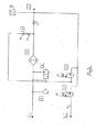
従来の装置を図1に示す。
コンプレッサ1は、加圧空気を空気ドライヤAを介し逆止弁5を通じて空気系統2に供給する。
通常の圧力逃し弁Fは、最大圧力に達した際にコンプレッサの供給ラインを抽気させる。A conventional apparatus is shown in FIG.
The
The normal pressure relief valve F bleeds the compressor supply line when the maximum pressure is reached.
電気的に作動する再生弁Dは、ばねにより閉鎖するが、これを開いて空気式システム2から制限部6を通して空気ドライヤAに空気が逆流できるようにする。
電気的に作動する指令弁Cも、ばねにより閉鎖し、この状態では、コンプレッサアンローダ4への信号ライン7は排気出口に通じている。The electrically actuated regenerative valve D is closed by a spring but is opened to allow air to flow back from the
The electrically operated command valve C is also closed by a spring, and in this state, the signal line 7 to the
空気ドライヤAの上流にある空気系統のための放出弁Bは、通常はばねにより閉鎖するが、信号ライン8内の充分な圧力が加わると開くことができる。他の信号ライン9も、系の圧力が所定最大値を超えたときに、放出弁Bを介して抽気することができる。 The discharge valve B for the air system upstream of the air dryer A is normally closed by a spring, but can be opened when sufficient pressure in the signal line 8 is applied. Other signal lines 9 can also be bleed through the discharge valve B when the system pressure exceeds a predetermined maximum value.
使用にあたり、コンプレッサ1は、空気ドライヤAを通して空気系統2を充填する。空気系統2において最大圧力に達した場合には、指令弁Cが電気的に作動して信号ライン8への供給出口に信号圧力を送ることができる。この信号圧力により放出弁Bが開き、従って、コンプレッサを、排気出口に接続し、放出弁Bの上流の系配管による僅かな抵抗に抗して自由に流動させることができる。信号ライン7は、随意的なものであり、コンプレッサアンローダ4(例えば、シリンダヘッド弁)を直接動作させ、放出弁Bの上流の配管により生ずるポンプ損失を解消するものである。 In use, the
空気系統2内の空気を用いることにより、指令弁Cの作動を停止させるのに充分な圧力低下を引き起こすことができ、この場合、信号ライン7,8内の圧力は、供給出口と排気出口とを接続することにより排気され、結果として、コンプレッサはオンロード(負荷)状態となる。 By using the air in the
空気系統2の圧力を検出する手段は、通常のものであり、例えば、コンプレッサの「オン」及びコンプレッサの「オフ」の弁に対応する最大及び最小の設定を有する圧力スイッチとすることができる。 Means for detecting the pressure in the
空気ドライヤAの再生が必要な場合には、弁C及びDの双方を附勢する。コンプレッサは、アンロード(無負荷)状態となり放出弁Bが開く。加圧空気は、制限部6を通じて抜き戻すことができ、従って、空気ドライヤAから水分を排出除去することができる。 When regeneration of the air dryer A is required, both valves C and D are energized. The compressor enters an unload (no load) state, and the discharge valve B opens. Pressurized air can be withdrawn back through the restricting portion 6, and thus moisture can be discharged and removed from the air dryer A.
再生弁Dは、圧力の低下、時間、排出された空気の湿度等の任意の所望の系パラメータによって閉鎖することができる。 The regenerative valve D can be closed by any desired system parameters such as pressure drop, time, exhaust air humidity, etc.
この比較的簡単な系によれば、電気的に作動する弁C,Dを用いることにより空気ドライヤAの再生を制御する。 According to this relatively simple system, regeneration of the air dryer A is controlled by using electrically operated valves C and D.
本発明による改良した空気系統を図2に示す。図1に対応する構成部材は、同じ参照符号及び機能を有する。
図2のシステムにおいて、再生弁Dは、信号ライン8内のパイロット圧により作動する。アンローダ信号ライン7は、電気的に作動する独立したアンローダ弁Eにより制御する。An improved air system according to the present invention is shown in FIG. Components corresponding to FIG. 1 have the same reference numerals and functions.
In the system of FIG. 2, the regeneration valve D is operated by the pilot pressure in the signal line 8. The unloader signal line 7 is controlled by an independent electrically operated unloader valve E.
この構成によれば、アンローダ弁Eを電気的に作動させることによりアンローダ信号を発生することができる。放出弁Bは、閉鎖されたままであり、従って、コンプレッサと空気ドライヤとの間の加圧空気は排気されない。その結果、コンプレッサがオンロード(負荷)状態になった場合に、逆止弁5の上流の系を充填する必要がなく、従って、系の応答時間が向上すると共にエネルギー節約にもなる。 According to this configuration, the unloader signal can be generated by electrically operating the unloader valve E. The discharge valve B remains closed and therefore the pressurized air between the compressor and the air dryer is not exhausted. As a result, when the compressor is on-load, there is no need to fill the system upstream of the check valve 5, thus improving the system response time and saving energy.
指令弁Cを電気的に作動させることにより、パイロット圧によって放出弁B及び再生弁Dの双方を開き、上述したように空気ドライヤAの再生が起こるようにする。 By electrically operating the command valve C, both the release valve B and the regeneration valve D are opened by the pilot pressure so that the regeneration of the air dryer A occurs as described above.
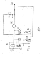
本発明による第二の系統を図3に示す。同様に、同じ参照符号を同じ機能を有する構成部材に用いる。
コンプレッサは、図2につき説明したように、独立してアンロード(無負荷)状態にすることができる。しかし、指令弁Cは、加圧流体を、逆止弁9及び制限部10を具える組立体Gを介して空気ドライヤAの下流のポイントに直接供給する。従って、空気ドライヤAの再生が必要な際には、指令弁C及びアンローダ弁Eを作動させ、放出弁Bを開くとともに指令弁Cを介して再生するための空気を流すことができる。この構成では、比較的高価な再生弁Dを簡単な逆止弁9及び制限部10で代用している。A second system according to the present invention is shown in FIG. Similarly, the same reference numerals are used for components having the same function.
The compressor can be independently unloaded (unloaded) as described with reference to FIG. However, the command valve C supplies pressurized fluid directly to a point downstream of the air dryer A via an assembly G comprising a check valve 9 and a restriction 10. Accordingly, when the air dryer A needs to be regenerated, the command valve C and the unloader valve E can be operated to open the discharge valve B and allow air to be regenerated through the command valve C to flow. In this configuration, the relatively expensive regenerative valve D is replaced with a simple check valve 9 and a restriction unit 10.
また、図3には、系の圧力に比例して電気信号電圧を発生するための圧力−電圧変換器12を示す。このような信号電圧は、電気的に作動する弁C,D,Eの動作を決定するために全ての実施例において使用することができる。 FIG. 3 shows a pressure-voltage converter 12 for generating an electric signal voltage in proportion to the system pressure. Such a signal voltage can be used in all embodiments to determine the operation of the electrically operated valves C, D, E.
本発明による第三の系統を図4に示すが、この系統は、アンロード(無負荷)状態になった際に下流の圧力を許容し得ない種類のコンプレッサを用いるようになっている。この系統は、図3のものと類似のものであり、共通する構成部材には同じ参照符号を用いている。 A third system according to the present invention is shown in FIG. 4, and this system uses a type of compressor that cannot tolerate downstream pressure when it enters an unloaded state. This system is similar to that of FIG. 3, and the same reference numerals are used for common components.
コンプレッサ1は、閉止弁Hを通して加圧空気を空気ドライヤAに供給する。ドレン弁Kは、コンプレッサ1と閉止弁Hとの間の空気回路部分を排気側に接続するよう動作し得る。 The
図に示されている通り、この空気回路は受動的なものであり、閉止弁H及びドレン弁Kは、それぞれ対応の復帰ばねにより端部位置に押圧されている。増大するコンプレッサ圧力はパイロット圧として閉止弁Hの頂部(図面で見て)に作用し、所定の最小圧力においてこの閉止弁が開き加圧空気を空気ドライヤAに供給する。 As shown in the figure, this air circuit is passive, and the closing valve H and the drain valve K are each pressed to the end position by the corresponding return spring. The increasing compressor pressure acts as a pilot pressure on the top of the shut-off valve H (as seen in the drawing), which opens at a predetermined minimum pressure and supplies pressurized air to the air dryer A.
遮断圧力において、アンローダ弁Eが電気的に作動して信号圧力を信号ライン7に供給し、コンプレッサ1をアンロード(無負荷)状態にする。信号圧力は、信号ライン11にも供給され、これによりドレン弁Kが開いた状態となり、また、閉止弁Hを閉鎖状態に向けて押圧する。従って、コンプレッサ1の出力ポートは、ドレン弁Kを介して排気側に開くが、閉止弁Hの下流の圧力は維持される。この構成によれば、システムはより速くポンプ送給することができるが、その理由は、コンプレッサのアンロード(無負荷)状態中に、コンプレッサ1及び空気ドライヤA間の加圧空気の全てが失われるわけではないためである。空気ドライヤAの再生は、図3につき説明した通りであり、弁C及びEを同時に電気的に作動させたときに行われる。 At the shut-off pressure, the unloader valve E is electrically operated to supply the signal pressure to the signal line 7 to put the
Claims (9)
前記再生弁は、信号ラインを介して前記指令弁に接続されており、前記指令弁の入口と供給出口とが接続されると、前記信号ライン内のパイロット圧により開かれ、再生用の逆流を許容するよう動作可能である
ことを特徴とする車両用空気ブレーキシステム。 A source of pressurized fluid, an air dryer downstream of the supply source, an air consumption circuit downstream of the air dryer, and the supply source is paused on demand to provide pressurized air to the air consumption circuit Control means for allowing the air to flow back to the drain valve through the air dryer, the control means comprising a regeneration valve, an inlet connected to the air consumption circuit and the drain A pneumatic brake system for a vehicle comprising a command valve having a supply outlet interactively connected to the valve;
The regeneration valve is connected to the command valve via a signal line, and when the inlet and the supply outlet of the command valve are connected , the regeneration valve is opened by a pilot pressure in the signal line, and a reverse flow for regeneration is generated. An air brake system for vehicles, characterized in that it is operable to allow.
Applications Claiming Priority (3)
| Application Number | Priority Date | Filing Date | Title |
|---|---|---|---|
| GB0023350.2 | 2000-09-22 | ||
| GBGB0023350.2A GB0023350D0 (en) | 2000-09-22 | 2000-09-22 | Vehicle air braking system |
| PCT/GB2001/004132 WO2002024506A1 (en) | 2000-09-22 | 2001-09-14 | Vehicle air braking system |
Publications (2)
| Publication Number | Publication Date |
|---|---|
| JP2004509016A JP2004509016A (en) | 2004-03-25 |
| JP5265839B2 true JP5265839B2 (en) | 2013-08-14 |
Family
ID=9899988
Family Applications (1)
| Application Number | Title | Priority Date | Filing Date |
|---|---|---|---|
| JP2002528543A Expired - Fee Related JP5265839B2 (en) | 2000-09-22 | 2001-09-14 | Air brake system for vehicles |
Country Status (9)
| Country | Link |
|---|---|
| US (2) | US20040026993A1 (en) |
| EP (1) | EP1318936B1 (en) |
| JP (1) | JP5265839B2 (en) |
| KR (1) | KR100773449B1 (en) |
| AU (1) | AU2001287863A1 (en) |
| BR (1) | BR0114063A (en) |
| DE (1) | DE60121006T2 (en) |
| GB (1) | GB0023350D0 (en) |
| WO (1) | WO2002024506A1 (en) |
Families Citing this family (23)
| Publication number | Priority date | Publication date | Assignee | Title |
|---|---|---|---|---|
| DE102005057004B3 (en) * | 2005-11-30 | 2007-04-05 | Knorr-Bremse Systeme für Nutzfahrzeuge GmbH | Compressed air preparation device for brake force adjusting system of commercial vehicle, has excited first solenoid controlled valve, with which pressure essentially remains in a line between compressor and stop valve |
| DE102006023681B4 (en) * | 2006-05-19 | 2009-07-02 | Knorr-Bremse Systeme für Nutzfahrzeuge GmbH | Method for controlling or regulating the air pressure in a compressed air supply device |
| CN101646481B (en) | 2007-01-31 | 2013-07-24 | Spx流体技术美国公司 | Integral sweep controller for gas membrane separation device |
| DE102008004807B4 (en) * | 2007-02-07 | 2012-10-31 | Knorr-Bremse Systeme für Nutzfahrzeuge GmbH | Compressed air supply system and method for operating a compressed air supply system |
| DE102007008160A1 (en) | 2007-02-19 | 2008-08-21 | Knorr-Bremse Systeme für Nutzfahrzeuge GmbH | Air compressor for commercial vehicle, comprises load relieving switching device for switching air compressor between idle phase and load phase |
| DE102007009768B4 (en) | 2007-02-27 | 2009-11-12 | Knorr-Bremse Systeme für Nutzfahrzeuge GmbH | Compressed air supply device for a commercial vehicle and method for operating a compressed air supply device |
| DE102007009767B4 (en) | 2007-02-27 | 2009-11-12 | Knorr-Bremse Systeme für Nutzfahrzeuge GmbH | Compressed air supply device for a commercial vehicle and method for operating a compressed air supply device |
| DE102007011256B4 (en) * | 2007-03-08 | 2009-02-05 | Knorr-Bremse Systeme für Nutzfahrzeuge GmbH | Compressed air supply device with improved regeneration capability |
| DE102007013671A1 (en) | 2007-03-19 | 2008-09-25 | Knorr-Bremse Systeme für Nutzfahrzeuge GmbH | Compressed air supply device for a commercial vehicle and method for operating a compressed air supply device |
| DE102007013673B4 (en) | 2007-03-19 | 2009-07-02 | Knorr-Bremse Systeme für Nutzfahrzeuge GmbH | Compressed air supply device for a commercial vehicle and method for operating a compressed air supply device |
| DE102007013672A1 (en) * | 2007-03-19 | 2008-09-25 | Knorr-Bremse Systeme für Nutzfahrzeuge GmbH | Compressed air supply device for a commercial vehicle and method for operating a compressed air supply device |
| DE102008026103A1 (en) * | 2008-05-30 | 2009-12-03 | Knorr-Bremse Systeme für Nutzfahrzeuge GmbH | Air dryer with integrated regeneration control and method for operating an air dryer |
| DE102010018949A1 (en) * | 2010-04-30 | 2011-11-03 | Wabco Gmbh | Compressed air treatment device, compressed air supply system with a compressed air treatment device and processing module therefor and method for operating a compressed air treatment device, control module and vehicle with a compressed air treatment device |
| DE102010024476A1 (en) † | 2010-06-21 | 2011-12-22 | Wabco Gmbh | Compressed air control device, compressed air control method, electronic control device, compressed air supply system, compressed air supply method and vehicle |
| DE102011011630B4 (en) * | 2011-02-17 | 2021-11-04 | Knorr-Bremse Systeme für Nutzfahrzeuge GmbH | Compressed air supply device for a commercial vehicle and method for operating a compressed air supply device |
| DE102012102490C5 (en) | 2012-03-22 | 2022-12-01 | Haldex Brake Products Aktiebolag | Compressed air treatment device for a commercial vehicle |
| EP2789512B2 (en) | 2013-04-12 | 2021-08-25 | Haldex Brake Products GmbH | Compressed air supply device for a commercial vehicle |
| US10519647B2 (en) | 2016-06-05 | 2019-12-31 | Rebox Containers Inc | Shipping container expansion insert |
| JP7099962B2 (en) * | 2016-12-08 | 2022-07-12 | ナブテスコオートモーティブ株式会社 | Air supply system |
| JP7269004B2 (en) * | 2018-12-28 | 2023-05-08 | ナブテスコオートモーティブ株式会社 | air supply system |
| JP7226992B2 (en) * | 2018-12-28 | 2023-02-21 | ナブテスコオートモーティブ株式会社 | air supply system |
| DE102019130837B3 (en) * | 2019-11-15 | 2021-04-01 | Dr. Ing. H.C. F. Porsche Aktiengesellschaft | Method for regenerating a dryer of an air suspension system of an electric vehicle and an air suspension system |
| CN114604218B (en) * | 2022-03-16 | 2022-11-11 | 东风商用车有限公司 | Air dryer, air brake control system and vehicle |
Family Cites Families (28)
| Publication number | Priority date | Publication date | Assignee | Title |
|---|---|---|---|---|
| US1965070A (en) * | 1932-01-19 | 1934-07-03 | William J Cumming | Air compressor governor |
| JPS5812861A (en) * | 1981-07-17 | 1983-01-25 | Diesel Kiki Co Ltd | Pressure control device for air piping system of car |
| DE3139683C2 (en) * | 1981-10-06 | 1986-02-20 | Robert Bosch Gmbh, 7000 Stuttgart | Air drying device |
| DE3139682A1 (en) * | 1981-10-06 | 1983-05-05 | Robert Bosch Gmbh, 7000 Stuttgart | Air-drying device for compressed air system |
| JPS58156783A (en) * | 1982-03-11 | 1983-09-17 | Honda Motor Co Ltd | Check valve |
| US4487617A (en) * | 1983-08-22 | 1984-12-11 | The Bendix Corporation | Mechanism for cleaning and drying compressed gases |
| JPS6049107A (en) * | 1983-08-26 | 1985-03-18 | Nippon Air Brake Co Ltd | Pressure-source apparatus for air-pressure circuit |
| JPS61272479A (en) * | 1985-05-25 | 1986-12-02 | Nippon Air Brake Co Ltd | Compressed air dehumidifying device |
| DE3542975A1 (en) * | 1985-12-05 | 1987-06-11 | Wabco Westinghouse Fahrzeug | LEVEL CONTROL DEVICE FOR VEHICLES WITH AIR SPRINGS |
| JPS62149320A (en) * | 1985-12-25 | 1987-07-03 | Nippon Air Brake Co Ltd | Pneumatic circuit device |
| DE3923882C2 (en) | 1989-03-02 | 2000-06-15 | Wabco Gmbh & Co Ohg | Control device for a compressor that delivers compressed air |
| JPH0427412A (en) * | 1990-05-19 | 1992-01-30 | Tokico Ltd | Air drier |
| US5145495A (en) * | 1991-06-13 | 1992-09-08 | Allied-Signal Inc. | Air dryer purge cycle timing control |
| JPH0552184A (en) * | 1991-08-23 | 1993-03-02 | Nabco Ltd | Pressure air supply device |
| US5378266A (en) * | 1993-08-02 | 1995-01-03 | Alliedsignal Inc. | Air dryer system |
| US5427609A (en) * | 1993-09-14 | 1995-06-27 | Horton Industries, Inc. | Device for cleaning and drying compressed gas |
| DE19515895A1 (en) | 1995-04-29 | 1996-10-31 | Bosch Gmbh Robert | Compressed air supply device for vehicle compressed air systems and method for controlling the compressed air supply device |
| DE19523219A1 (en) * | 1995-06-27 | 1997-01-02 | Bosch Gmbh Robert | Device for time-dependent control of the regeneration period of an air dryer |
| US5678900A (en) * | 1995-12-19 | 1997-10-21 | Grau Gmbh | Unloader for a source of air under pressure on vehicles |
| DE19620851C2 (en) | 1996-05-23 | 1999-12-09 | Knorr Bremse Systeme | Air conditioning arrangement for compressed air, in particular for pneumatic brake systems of motor vehicles |
| US5592754A (en) * | 1996-06-07 | 1997-01-14 | Alliedsignal Truck Brake Systems Co. | Electronic control of compressor unloader and air dryer purge |
| GB9706227D0 (en) * | 1997-03-26 | 1997-05-14 | Wabco Automotive Uk | Vent valve |
| DE19724747C1 (en) * | 1997-06-12 | 1998-06-25 | Continental Ag | Level regulator for motor vehicles with pneumatic springs |
| DE19834705C5 (en) | 1998-07-31 | 2006-04-06 | Knorr-Bremse Systeme für Nutzfahrzeuge GmbH | Compressed air supply device for vehicle compressed air systems and method for saving energy in compressed air supply devices |
| DE19835491C2 (en) * | 1998-08-06 | 2000-05-25 | Continental Ag | Level control device for vehicles with air springs |
| GB9920694D0 (en) * | 1999-09-03 | 1999-11-03 | Wabco Automotive Uk | Vehicle air supply systems |
| GB0113205D0 (en) * | 2001-05-31 | 2001-07-25 | Wabco Automotive Uk Ltd | Regeneration of air dryer |
| DE102005033083B3 (en) * | 2005-07-15 | 2006-12-28 | Knorr-Bremse Systeme für Nutzfahrzeuge GmbH | Air treatment method for utility vehicle pneumatic brake systems, comprises air drier which is regenerated by passing air from pressure tank through it, amount used being increased if condensate is detected in air downstream from drier |
-
2000
- 2000-09-22 GB GBGB0023350.2A patent/GB0023350D0/en not_active Ceased
-
2001
- 2001-09-14 AU AU2001287863A patent/AU2001287863A1/en not_active Abandoned
- 2001-09-14 EP EP01967488A patent/EP1318936B1/en not_active Revoked
- 2001-09-14 DE DE60121006T patent/DE60121006T2/en not_active Revoked
- 2001-09-14 US US10/381,031 patent/US20040026993A1/en not_active Abandoned
- 2001-09-14 BR BR0114063-9A patent/BR0114063A/en not_active IP Right Cessation
- 2001-09-14 KR KR1020037003341A patent/KR100773449B1/en active IP Right Grant
- 2001-09-14 JP JP2002528543A patent/JP5265839B2/en not_active Expired - Fee Related
- 2001-09-14 WO PCT/GB2001/004132 patent/WO2002024506A1/en active IP Right Grant
-
2012
- 2012-03-26 US US13/429,612 patent/US8801111B2/en not_active Expired - Fee Related
Also Published As
| Publication number | Publication date |
|---|---|
| US20120181851A1 (en) | 2012-07-19 |
| KR100773449B1 (en) | 2007-11-05 |
| DE60121006D1 (en) | 2006-08-03 |
| US20040026993A1 (en) | 2004-02-12 |
| AU2001287863A1 (en) | 2002-04-02 |
| EP1318936B1 (en) | 2006-06-21 |
| GB0023350D0 (en) | 2000-11-08 |
| DE60121006T2 (en) | 2006-12-14 |
| US8801111B2 (en) | 2014-08-12 |
| BR0114063A (en) | 2003-07-22 |
| JP2004509016A (en) | 2004-03-25 |
| KR20030036757A (en) | 2003-05-09 |
| EP1318936A1 (en) | 2003-06-18 |
| WO2002024506A1 (en) | 2002-03-28 |
Similar Documents
| Publication | Publication Date | Title |
|---|---|---|
| JP5265839B2 (en) | Air brake system for vehicles | |
| US6540308B1 (en) | Electronic compressed-air processing system | |
| JP6403678B2 (en) | Compressed air supply device and method of operating compressed air supply device | |
| JP5187664B2 (en) | Compressed air supply system for vehicle and air dryer | |
| US5678900A (en) | Unloader for a source of air under pressure on vehicles | |
| KR102011525B1 (en) | Compressed air processing system and method for operating a compressed air processing system | |
| JP7019676B2 (en) | Parking brake valve device that drives a spring-loaded stop brake | |
| CN1329232C (en) | Vehicle air supply system | |
| KR100647561B1 (en) | Vehicle air supply systems | |
| CN107206992B (en) | Device and method for supplying compressed air to a commercial vehicle | |
| CN107548438B (en) | Switching assembly, in particular for the preparation of compressed air | |
| US8616231B2 (en) | Valve device for a compressed air supply device and compressed air supply system | |
| JPH03246149A (en) | Pressure source for vehicle | |
| US6991001B2 (en) | Compressed air control apparatus for compressed air systems of motor vehicles | |
| US20030213361A1 (en) | Service reservoir purge of air dryers in pump-off mode | |
| US6050651A (en) | Vent valve and method of operation thereof | |
| EP3995373A1 (en) | Air dryer with direct solenoid control | |
| JP2717803B2 (en) | Compressed air pressure source device | |
| JPH0112531B2 (en) | ||
| JPH0356137Y2 (en) | ||
| JPS6245106Y2 (en) | ||
| JPH085885Y2 (en) | Quick release valve | |
| JPH0525687Y2 (en) | ||
| JPH029191B2 (en) | ||
| JPH0644973B2 (en) | Air dryer equipment |
Legal Events
| Date | Code | Title | Description |
|---|---|---|---|
| A621 | Written request for application examination |
Free format text: JAPANESE INTERMEDIATE CODE: A621 Effective date: 20080812 |
|
| RD03 | Notification of appointment of power of attorney |
Free format text: JAPANESE INTERMEDIATE CODE: A7423 Effective date: 20080812 |
|
| A131 | Notification of reasons for refusal |
Free format text: JAPANESE INTERMEDIATE CODE: A131 Effective date: 20110913 |
|
| A977 | Report on retrieval |
Free format text: JAPANESE INTERMEDIATE CODE: A971007 Effective date: 20110914 |
|
| A601 | Written request for extension of time |
Free format text: JAPANESE INTERMEDIATE CODE: A601 Effective date: 20111209 |
|
| A602 | Written permission of extension of time |
Free format text: JAPANESE INTERMEDIATE CODE: A602 Effective date: 20111216 |
|
| A601 | Written request for extension of time |
Free format text: JAPANESE INTERMEDIATE CODE: A601 Effective date: 20120112 |
|
| A602 | Written permission of extension of time |
Free format text: JAPANESE INTERMEDIATE CODE: A602 Effective date: 20120119 |
|
| A601 | Written request for extension of time |
Free format text: JAPANESE INTERMEDIATE CODE: A601 Effective date: 20120210 |
|
| A602 | Written permission of extension of time |
Free format text: JAPANESE INTERMEDIATE CODE: A602 Effective date: 20120217 |
|
| A521 | Written amendment |
Free format text: JAPANESE INTERMEDIATE CODE: A523 Effective date: 20120312 |
|
| A131 | Notification of reasons for refusal |
Free format text: JAPANESE INTERMEDIATE CODE: A131 Effective date: 20120904 |
|
| TRDD | Decision of grant or rejection written | ||
| A01 | Written decision to grant a patent or to grant a registration (utility model) |
Free format text: JAPANESE INTERMEDIATE CODE: A01 Effective date: 20130423 |
|
| A61 | First payment of annual fees (during grant procedure) |
Free format text: JAPANESE INTERMEDIATE CODE: A61 Effective date: 20130502 |
|
| R150 | Certificate of patent or registration of utility model |
Ref document number: 5265839 Country of ref document: JP Free format text: JAPANESE INTERMEDIATE CODE: R150 Free format text: JAPANESE INTERMEDIATE CODE: R150 |
|
| R250 | Receipt of annual fees |
Free format text: JAPANESE INTERMEDIATE CODE: R250 |
|
| R250 | Receipt of annual fees |
Free format text: JAPANESE INTERMEDIATE CODE: R250 |
|
| S111 | Request for change of ownership or part of ownership |
Free format text: JAPANESE INTERMEDIATE CODE: R313113 |
|
| S531 | Written request for registration of change of domicile |
Free format text: JAPANESE INTERMEDIATE CODE: R313531 |
|
| R350 | Written notification of registration of transfer |
Free format text: JAPANESE INTERMEDIATE CODE: R350 |
|
| R250 | Receipt of annual fees |
Free format text: JAPANESE INTERMEDIATE CODE: R250 |
|
| LAPS | Cancellation because of no payment of annual fees |