JP5264876B2 - Storage - Google Patents
Storage Download PDFInfo
- Publication number
- JP5264876B2 JP5264876B2 JP2010291621A JP2010291621A JP5264876B2 JP 5264876 B2 JP5264876 B2 JP 5264876B2 JP 2010291621 A JP2010291621 A JP 2010291621A JP 2010291621 A JP2010291621 A JP 2010291621A JP 5264876 B2 JP5264876 B2 JP 5264876B2
- Authority
- JP
- Japan
- Prior art keywords
- main body
- storage
- front edge
- reinforcing member
- bent portion
- Prior art date
- Legal status (The legal status is an assumption and is not a legal conclusion. Google has not performed a legal analysis and makes no representation as to the accuracy of the status listed.)
- Expired - Fee Related
Links
- 238000003860 storage Methods 0.000 title claims description 55
- 230000003014 reinforcing effect Effects 0.000 claims description 41
- 229910001220 stainless steel Inorganic materials 0.000 claims description 11
- 239000010935 stainless steel Substances 0.000 claims description 11
- 229920005989 resin Polymers 0.000 claims description 4
- 239000011347 resin Substances 0.000 claims description 4
- 238000005452 bending Methods 0.000 description 17
- 239000002184 metal Substances 0.000 description 15
- 239000011162 core material Substances 0.000 description 13
- 238000010411 cooking Methods 0.000 description 7
- 230000002787 reinforcement Effects 0.000 description 6
- 239000000463 material Substances 0.000 description 4
- 230000009467 reduction Effects 0.000 description 4
- NJPPVKZQTLUDBO-UHFFFAOYSA-N novaluron Chemical compound C1=C(Cl)C(OC(F)(F)C(OC(F)(F)F)F)=CC=C1NC(=O)NC(=O)C1=C(F)C=CC=C1F NJPPVKZQTLUDBO-UHFFFAOYSA-N 0.000 description 3
- 238000000034 method Methods 0.000 description 2
- 235000013599 spices Nutrition 0.000 description 2
- 230000009466 transformation Effects 0.000 description 2
- 239000013585 weight reducing agent Substances 0.000 description 2
- 239000004278 EU approved seasoning Substances 0.000 description 1
- 239000002928 artificial marble Substances 0.000 description 1
- 230000008901 benefit Effects 0.000 description 1
- 239000012141 concentrate Substances 0.000 description 1
- 238000010586 diagram Methods 0.000 description 1
- 235000011194 food seasoning agent Nutrition 0.000 description 1
- 230000006872 improvement Effects 0.000 description 1
- 238000009434 installation Methods 0.000 description 1
- 230000014759 maintenance of location Effects 0.000 description 1
- 238000012986 modification Methods 0.000 description 1
- 230000004048 modification Effects 0.000 description 1
- 238000005192 partition Methods 0.000 description 1
- 230000008569 process Effects 0.000 description 1
- 239000012779 reinforcing material Substances 0.000 description 1
- 238000000926 separation method Methods 0.000 description 1
- 229920003002 synthetic resin Polymers 0.000 description 1
- 239000000057 synthetic resin Substances 0.000 description 1
- XLYOFNOQVPJJNP-UHFFFAOYSA-N water Substances O XLYOFNOQVPJJNP-UHFFFAOYSA-N 0.000 description 1
Images


Classifications
-
- A—HUMAN NECESSITIES
- A47—FURNITURE; DOMESTIC ARTICLES OR APPLIANCES; COFFEE MILLS; SPICE MILLS; SUCTION CLEANERS IN GENERAL
- A47B—TABLES; DESKS; OFFICE FURNITURE; CABINETS; DRAWERS; GENERAL DETAILS OF FURNITURE
- A47B88/00—Drawers for tables, cabinets or like furniture; Guides for drawers
- A47B88/40—Sliding drawers; Slides or guides therefor
-
- A—HUMAN NECESSITIES
- A47—FURNITURE; DOMESTIC ARTICLES OR APPLIANCES; COFFEE MILLS; SPICE MILLS; SUCTION CLEANERS IN GENERAL
- A47B—TABLES; DESKS; OFFICE FURNITURE; CABINETS; DRAWERS; GENERAL DETAILS OF FURNITURE
- A47B67/00—Chests; Dressing-tables; Medicine cabinets or the like; Cabinets characterised by the arrangement of drawers
- A47B67/04—Chests of drawers; Cabinets characterised by the arrangement of drawers
-
- A—HUMAN NECESSITIES
- A47—FURNITURE; DOMESTIC ARTICLES OR APPLIANCES; COFFEE MILLS; SPICE MILLS; SUCTION CLEANERS IN GENERAL
- A47B—TABLES; DESKS; OFFICE FURNITURE; CABINETS; DRAWERS; GENERAL DETAILS OF FURNITURE
- A47B77/00—Kitchen cabinets
- A47B77/04—Provision for particular uses of compartments or other parts ; Compartments moving up and down, revolving parts
- A47B77/14—Provision for particular uses of compartments or other parts ; Compartments moving up and down, revolving parts by incorporation of racks or supports, other than shelves, for household utensils
Description
本発明は、被収納物を収納可能なスライド式の引出を備える収納庫に関する。 The present invention relates to a storage provided with a slide-type drawer capable of storing an object to be stored.
キッチンには、調理器具や調理材料、食器などを収納しておくために、多くの収納スペースが設けられている。このため天板(システムキッチンにおいてはワークトップ)の下には、引出や開き戸が設けられるのが通常である。近年では、引出などに収納される被収納物をある程度想定し、引出の大きさや仕切りの形状を工夫することにより、使い勝手の向上を図ることが行われている。 In the kitchen, many storage spaces are provided to store cooking utensils, cooking materials, tableware, and the like. For this reason, a drawer or a hinged door is usually provided under the top plate (worktop in the system kitchen). In recent years, it has been attempted to improve usability by devising the size of the drawer and the shape of the partition, assuming a certain amount of objects to be stored in the drawer.
顧客の幅広いニーズに応えるために、収納庫は木製のものやステンレス等からなる金属製のものなど各種ラインナップが取り揃えられているが、なかでも金属製の収納庫は、高級感や耐久性の高さにおいて人気があり、最近の主流となりつつある。例えば特許文献1では、背板と左右の側板を一枚の板材を折曲して一体に形成した背側板としてその下端に底板を、左右側板の前面上部に幕板を接合するようにした金属製キャビネットが開示されている。 In order to meet a wide range of customer needs, there are various lineups of storage such as wooden items and metal items made of stainless steel. Among them, metal storage items are highly luxurious and highly durable. It is popular in the field and is becoming the mainstream recently. For example, in Patent Document 1, a back plate and left and right side plates are integrally formed by bending a single plate material, and a bottom plate is joined to the lower end of the back plate, and a curtain plate is joined to the front upper part of the left and right side plates. A cabinet is disclosed.
しかしながら、特許文献1のキャビネットに限らず、金属製の収納庫は、上述したように高級感や耐久性においては木製の収納庫よりも優れるものの、コストパフォーマンスにおいては木製の収納庫に及ばない。また他の課題として、搬送作業や設置作業に要する労力を軽減するために軽量化が要請されている。したがって、従来の金属製の収納庫には更なる改良が望まれていて、低コスト化および軽量化を達成するためには、金属製の収納庫を構成する金属板の板厚を薄くすることが最も効果的である。 However, the metal storage is not limited to the cabinet disclosed in Patent Document 1, but is superior to the wooden storage in terms of luxury and durability as described above, but the cost performance does not reach that of the wooden storage. As another problem, weight reduction is required in order to reduce labor required for conveyance work and installation work. Therefore, further improvement is desired for the conventional metal storage, and in order to achieve a reduction in cost and weight, the thickness of the metal plate constituting the metal storage is reduced. Is the most effective.
ところで、一般的に、収納庫と床面との間には、収納庫後方に奥まった空間である蹴込みが設けられる。特許文献1では、補強材を組み付けた背側板と底板とからなる本体を、それよりも奥行きが浅く作られた台輪の上に載置することにより蹴込みを設けている。しかしこの方法であると、本体の背側板とは別に台輪の前板および側板となる金属板が必要となり部品数や組付け工数が増してしまう。この課題を解決するために発明者は鋭意検討し、本体の背側板を加工することにより台輪なしで蹴込みを設けることを考えた。 By the way, generally, a kick which is a space deep behind the storage is provided between the storage and the floor. In Patent Document 1, a kick is provided by placing a main body composed of a back side plate and a bottom plate assembled with a reinforcing material on a pedestal made shallower than that. However, this method requires a metal plate as a front plate and a side plate of the carriage, in addition to the back side plate of the main body, and increases the number of parts and assembly steps. In order to solve this problem, the inventor diligently studied and considered providing a kick without a wheel by processing the back plate of the main body.
台輪なしで蹴込みを設ける場合、本体の背側板の前側の下部を四角く切り欠くこととなる。しかし、上述した低コスト化および軽量化に対応するために板厚を薄くした金属板は、厚めの金属板に比べて剛性が低く撓みやすくなっている。このため、薄い金属板において下部を切り欠くような加工を施すと、切欠の角部に荷重(応力)が集中してその部分が撓み、側面部ひいては収納庫の変形が生じることが想定される。 When a kick is provided without a wheel, the lower part on the front side of the back plate of the main body is cut out in a square shape. However, a metal plate having a thin plate thickness to cope with the reduction in cost and weight described above has a lower rigidity and is more easily bent than a thick metal plate. For this reason, it is assumed that when a thin metal plate is processed such that the lower part is cut out, the load (stress) is concentrated on the corners of the cut out, the part is bent, and the side part and thus the storage box are deformed. .
本発明は、このような課題に鑑み、板厚が薄い金属板であっても撓みを生じさせることなく蹴込みを設けることができ、部品数や組付け工数の削減、ならびに低コスト化および軽量化を達成することが可能な収納庫を提供することを目的としている。 In view of such problems, the present invention can provide a kick-in without causing bending even if a metal plate is thin, reducing the number of parts and assembly steps, and reducing the cost and weight. The purpose is to provide a storage that can achieve this.
上記課題を解決するために、本発明にかかる収納庫の代表的な構成は、被収納物を収納可能なスライド式の引出を備える収納庫であって、少なくとも両側面がステンレス製の板状部材によって形成され引出を収容する本体部を備え、本体部は、その両側面において両側面の前縁の下端から下縁に至るまで後方に向かって傾斜する傾斜部と、その両側面各々の前縁および下縁においてコの字状に曲げ加工された屈曲部と、を有し、当該収納庫は、傾斜部に沿って配置され、前縁の屈曲部と下縁の屈曲部との両方に当接する樹脂製の補強部材を更に備えることを特徴とする。 In order to solve the above-mentioned problems, a typical configuration of a storage according to the present invention is a storage having a slide-type drawer capable of storing an object to be stored, and at least both side surfaces are plate-shaped members made of stainless steel. And a main body part that accommodates the drawer, and the main body part has an inclined part that is inclined rearward from the lower end to the lower edge of the front edge of each side surface on both side surfaces thereof, and the front edge of each of the both side surfaces thereof And a bent portion bent into a U-shape at the lower edge, and the storage is disposed along the inclined portion and contacts both the bent portion of the front edge and the bent portion of the lower edge. It further comprises a resin-made reinforcing member in contact therewith.
上記構成のように板状部材からなる本体部に傾斜部を設けることにより、本体部の側面と一体に蹴込みを設けることができ、部品数や組付け工数の削減を図ることができる。このとき、四角い切欠ではなく傾斜によって蹴込みを形成したことにより、荷重が集中しづらく、撓みの発生ひいては板状部材(金属板)の変形を抑制することができる。 By providing the inclined portion in the main body portion made of a plate-like member as in the above configuration, the kick can be provided integrally with the side surface of the main body portion, and the number of parts and assembly man-hours can be reduced. At this time, since the notch is formed by the inclination instead of the square notch, the load is difficult to concentrate, and the occurrence of the bending and the deformation of the plate member (metal plate) can be suppressed.
また本体部の両側面各々の前縁および下縁に屈曲部を設けることにより、かかる両側面の剛性の向上を図ることができる。ここで、可能であれば傾斜部にも屈曲部を設けることが好ましいが、傾斜部は曲げ加工することが困難である。そこで、上記のように補強部材を設けて傾斜部を補強している。補強部材は、前縁の屈曲部と下縁の屈曲部との両方に当接しているため、前縁からの荷重が下縁に伝わり、傾斜部への荷重が軽減され、撓みによる変形がより好適に防止される。したがって、上記構成であれば、蹴込みを本体部と一体に形成した場合であっても十分な強度を確保しながら本体部となる板状部材の板厚を低減することができ、低コスト化および軽量化を図ることが可能となる。 Further, by providing bent portions at the front edge and the lower edge of each side surface of the main body, the rigidity of the both side surfaces can be improved. Here, if possible, it is preferable to provide a bent portion in the inclined portion, but it is difficult to bend the inclined portion. Therefore, the inclined portion is reinforced by providing the reinforcing member as described above. Since the reinforcing member is in contact with both the bent portion of the front edge and the bent portion of the lower edge, the load from the front edge is transmitted to the lower edge, the load to the inclined portion is reduced, and deformation due to bending is further reduced. It is preferably prevented. Therefore, with the above configuration, even when the kick is formed integrally with the main body, the plate thickness of the plate-like member serving as the main body can be reduced while ensuring sufficient strength, and the cost can be reduced. In addition, the weight can be reduced.
上記の補強部材は、側面の前縁に設けられた屈曲部の端面を支持する段部を有するとよい。かかる構成によれば、収納庫上部の荷重が、本体部側面の前縁から補強部材の段部に確実に伝わることとなる。そして、その荷重は、補強部材を介して本体部側面の下縁に伝わって支持される。したがって、本体部側面の傾斜部にかかる荷重をより軽減することができ、その変形を更に抑制することが可能となる。 Said reinforcement member is good to have a step part which supports the end surface of the bending part provided in the front edge of the side surface. According to such a configuration, the load on the upper part of the storage is surely transmitted from the front edge of the side surface of the main body to the step portion of the reinforcing member. The load is transmitted to and supported by the lower edge of the side surface of the main body via the reinforcing member. Therefore, the load applied to the inclined portion on the side surface of the main body can be further reduced, and the deformation can be further suppressed.
上記の本体部は、その底面の前縁においてコの字状に曲げ加工された屈曲部を有し、当該収納庫は、底面の前縁に設けられた屈曲部に挿入される樹脂製の芯材を更に備え、補強部材は、芯材と共締めされるとよい。 The main body has a bent portion bent into a U shape at the front edge of the bottom surface, and the storage is a resin core inserted into the bent portion provided at the front edge of the bottom surface. The reinforcing member may be fastened together with the core member.
上記のように本体部底面の前縁においても屈曲部を設けることにより、底面の剛性の向上を図ることができる。そして、かかる屈曲部に芯材を挿入することにより、屈曲部の変形を好適に抑制可能となる。更に、補強部材と芯材とを共締めすることにより、1つの作業で2つの部材を同時に本体部に取り付けることができるため、収納庫の組立工数および収納庫廃棄時の解体工数の削減を図ることが可能となる。 As described above, by providing the bent portion at the front edge of the bottom surface of the main body, the rigidity of the bottom surface can be improved. And it becomes possible to suppress suitably a deformation | transformation of a bending part by inserting a core material in this bending part. Furthermore, by fastening the reinforcing member and the core material together, two members can be attached to the main body at the same time in one operation, thereby reducing the number of man-hours for assembling the storage case and the number of dismantling steps when the storage case is discarded. It becomes possible.
本発明によれば、板厚が薄い金属板であっても撓みを生じさせることなく蹴込みを設けることができ、部品数や組付け工数の削減、ならびに低コスト化および軽量化を達成することが可能な収納庫を提供することができる。 According to the present invention, even if a metal plate is thin, it is possible to provide a kick without causing bending, reducing the number of parts and assembling steps, and achieving reduction in cost and weight. Can be provided.
以下に添付図面を参照しながら、本発明の好適な実施形態について詳細に説明する。かかる実施形態に示す寸法、材料、その他具体的な数値などは、発明の理解を容易とするための例示に過ぎず、特に断る場合を除き、本発明を限定するものではない。なお、本明細書及び図面において、実質的に同一の機能、構成を有する要素については、同一の符号を付することにより重複説明を省略し、また本発明に直接関係のない要素は図示を省略する。 Hereinafter, preferred embodiments of the present invention will be described in detail with reference to the accompanying drawings. The dimensions, materials, and other specific numerical values shown in the embodiments are merely examples for facilitating understanding of the invention, and do not limit the present invention unless otherwise specified. In the present specification and drawings, elements having substantially the same function and configuration are denoted by the same reference numerals, and redundant description is omitted, and elements not directly related to the present invention are not illustrated. To do.
(キッチン)
図1は本実施形態にかかる収納庫を備えるキッチンを示す図である。キッチン100は一枚の天板110(ワークトップ)の下に複数の収納庫(キャビネット)を備えた、いわゆるシステムキッチンである。天板110は合成樹脂(人工大理石)やステンレスなどからなり、キッチン100の全体の上面を覆っている。また天板110には、組み込み式に取り付けられたコンロ112、平坦なテーブル面であり主に調理を行うのに利用される調理スペース114、天板110に一体形成されたシンク116が設けられる。
(kitchen)
FIG. 1 is a diagram illustrating a kitchen including a storage according to the present embodiment. The
天板110の下は、コンロ112本体が設置されているコンロキャビネット120と、調理スペース114に対応したベースキャビネット130と、シンク116が設置されているシンクキャビネット140といった各収納庫で構成される。各収納庫は収納スペースとして機能し、収納庫内の空きスペースには、コンロ112への配線や、シンク116および水栓への給排水管なども収容されている。このように、天板110の下では、天板110の上のシンク116やコンロ112といった各構成に対応した収納庫がその高さおよび奥行きを等しくして複数設けられている。
Under the
各収納庫は、被収納物を収納するために、様々な大きさのスライド式の引出を設けている。コンロキャビネット120は、上部にコンロ112のグリル112aおよび操作パネル112bを備え、その脇には調味料などの小物を収納するための小さな引出であるスパイスボックス122が配設されている。コンロキャビネット120の中央部(グリル112aの下)には幅の広い大きな引出124が配設され、鍋やボウルなどの比較的大きな調理器具を収納することが可能になっている。またコンロキャビネット120の下部の床近傍には、引出式の足元収納である足下収納庫126が配設されている。同様に、ベースキャビネット130には複数の引出132、134および足下収納庫136が配設され、シンクキャビネット140には引出144、および足下収納庫146が配設されている。
Each storage is provided with sliding drawers of various sizes in order to store the objects to be stored. The
(収納庫)
次に、本実施形態の特徴である収納庫について説明する。なお、以下の説明では、上述したコンロキャビネット120、ベースキャビネット130、シンクキャビネット140のうち、ベースキャビネット130を例示するが、本発明はコンロキャビネット120およびシンクキャビネット140にも適用可能である。
(Storage)
Next, the storage which is a feature of this embodiment will be described. In the following description, the
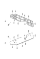
図2は、本実施形態にかかる収納庫であるベースキャビネット130の本体部の斜視図であり、理解を容易にするために、図1の本体部から引出132および134、ならびに足下収納庫136を取り外した状態を示している。図3は、図2の本体部の分解斜視図および正面図であり、図3(a)は図2の本体部の分解斜視図であり、図3(b)は図2の本体部の正面図である。
FIG. 2 is a perspective view of the main body of the
ベースキャビネット130は、引出132および134、足下収納庫136(図1参照)、ならびにそれらを収容する本体部200を備える(図2参照)。図3(a)に示すように、本体部200の右側面200aおよび左側面200b(以下、これらを総じて両側面と称する。)、背面200cは、ステンレス製の板状部材をコの字状に折り曲げることにより一体に形成される。このように本体部200をステンレス製(金属製)とすることにより、高級感や耐久性が得られ、両側面および背面200cを1枚板で構成することにより、部材数の削減、ひいてはそれらの組立工数の削減が可能となる。
The
本体部200の両側面の前縁の上部には、かかる両側面および背面200cとは別部材からなるステンレス製の前板が前面200dとして取り付けられる。また両側面および背面200cの下縁にはステンレス製の底板が底面200eとして取り付けられる。これにより、本体部200が図2に示す状態となる。
A stainless steel front plate made of a member different from the both side surfaces and the
なお、本実施形態においては、コの字状に折り曲げたステンレス製の1枚板により両側面および背面200cを構成したが、かかる構成は一例であり、少なくとも両側面がステンレス製の板状部材によって形成されていればよい。また背面200c、前面200dおよび底面200eにもステンレス製の板状部材を用いることとしたが、これに限定するものではない。しかし、かかる構成によれば、素材の統一感が得られるため高い意匠性が得られたり、ベースキャビネット130を廃棄する際の分別作業が容易になったりするという利点を得ることができる。
In this embodiment, the both side surfaces and the
図3(b)に示すように、本体部200の両側面の内側には、高さ方向においてレール210a〜210fが左右一対に取り付けられている。これにより、引出132および134や足下収納庫136(図1参照)の側面に設けられたプーリ(不図示)をレール210a〜210fに挿入して、引出132および134や足下収納庫136をスライド可能となる。
As shown in FIG.3 (b), the
また図2および図3(b)に示すように、本体部200の両側面の外側には、レール210a〜210fに対応する位置に、高さ方向においてネジ受けプレート220a〜220fが左右一対に取り付けられている。これにより、両側面を構成する板状部材の厚みを低減した場合であっても、十分な強度をもってレール210a〜210fをかかる両側面に取り付けることが可能となる。
Further, as shown in FIGS. 2 and 3B, a pair of left and right
本実施形態の特徴として、図3に示すように、本体部200の右側面200aには、その前縁202aの下端から下縁204aに至るまで後方に向かって傾斜する傾斜部206aが形成されている。同様に、本体部200の左側面200bには、その前縁202bの下端から下縁204bに至るまで後方に向かって傾斜する傾斜部206bが形成されている。かかる構成により、本体部200の両側面と一体に蹴込みを設けることができるため、従来のように台輪(台座)によって蹴込みを設ける構成と比して部品数や組付け工数の削減を図ることができる。また傾斜部206aおよび206bによって蹴込みを形成すれば、四角い切欠のように荷重が集中する箇所が生じづらいため、撓みの発生ひいては板状部材(金属板)の変形を抑制することができる。
As a feature of the present embodiment, as shown in FIG. 3, the
また本実施形態では、上述した本体部200の側面の縁に屈曲部が設けられる。図4は、図3(a)の各断面図であり、図4(a)は図3(a)のA−A断面図であり、図4(b)は図3(a)のB−B断面図であり、図4(c)は図3(a)のC−C断面図である。なお、右側面200aおよび左側面200bは左右対称に同一形状であるため、右側面200aを例示して説明する。
In the present embodiment, a bent portion is provided at the edge of the side surface of the
詳細には、図4(a)に示すように、本体部200の右側面200aの前縁202aには、そこを本体部200の外側に曲げ加工し、更にその先端を右側面200aに並行になるように曲げ加工することによって、すなわち前縁202aをコの字状に曲げ加工することによって屈曲部202cが形成されている。同様に、図4(b)に示すように、本体部の200aの下縁204aには、そこを本体部200の外側にコの字状に曲げ加工することによって屈曲部204cが形成されている。これにより、右側面200aの剛性を十分に確保することができるため、その薄板化を図ることができる。
Specifically, as shown in FIG. 4 (a), the
更に、本実施形態においては、両側面だけでなく、本体部200の底面200eの前縁205aにも屈曲部205cを形成している。図4(c)に示すように、屈曲部205cは、前縁205aを本体部200の下側にコの字状に曲げ加工することによって形成されている。これにより、両側面のみならず底面200eの剛性も向上させることができるため、その薄板化ひいては更なる軽量化を促進することが可能となる。
Furthermore, in this embodiment, the
なお、可能であれば傾斜部206aおよび206bにも屈曲部を設けることが好ましいものの、図3(a)からもわかるように、傾斜部206aおよび206bには屈曲させることができる曲げ代がない。また、傾斜部206aおよび206bに曲げ加工のための型を当てようとすると、前縁202aの屈曲部202cや下縁204aの屈曲部204cが邪魔になる。このため、傾斜部206aおよび206bを曲げ加工して屈曲部を形成することは困難である。そこで、本実施形態の最たる特徴として、傾斜部206aおよび206bに沿って、そこを補強するための補強部材250を配置している(図2参照)。
Although it is preferable that the
図5は、補強部材250の詳細を示す図であり、図5(a)は補強部材250の正面斜視図であり、図5(b)は補強部材250の背面斜視図である。図6は、本体部200への補強部材250の取付を説明する図であり、図6(a)は補強部材250を取り付ける前の本体部200を示し、図6(b)は補強部材250を取り付けた後の本体部200を示している。なお、右側面200aおよび左側面200b、ならびにそれらに取り付けられる補強部材250は左右対称に同一の構成を有するため、以下、右側面200aおよびそこに取り付けられる補強部材250を例示して説明する。
5A and 5B are views showing details of the reinforcing
図5に示す補強部材250は、樹脂製の部材であり、右側面200aの下部において、その前縁202aの屈曲部202cと下縁204aの屈曲部204cとの両方に当接するように配置される(図2および図3(a)参照)。詳細には、図5(a)および(b)に示すように、補強部材250の側面には、屈曲部202cに当接する第1当接面252aと、屈曲部204cに当接する第2当接面252bとが設けられていて、それらの間には右側面200aの傾斜部206aに沿う傾斜面252cが設けられている。
The reinforcing
一方、上記の第1当接面252a、第2当接面252bおよび傾斜面252cが設けられた側面と反対側の側面には、後退部254が形成されている。これによれば、図6(a)に示すように、右側面200aの下部に取り付けられた際における補強部材250とネジ受けプレート220cとの干渉を招くことがない。
On the other hand, a receding
また補強部材250の正面256aには、かかる補強部材250をその厚み方向において背面256bに向かって貫通するネジ穴258aおよびネジ穴258b、ならびに連結孔258cが形成されている。ネジ穴258aおよび258bは、右側面200aへの補強部材250の取付時に使用され、連結孔258cは、コンロキャビネット120等の他の収納庫の本体部と本体部200との連結時に使用される。
Further, a
更に、傾斜部206aへの荷重をより確実に軽減するために、本実施形態では第1当接面252aの下端(傾斜面252cの上端)に段部260を設けている。後退部254は、補強部材250の、第1当接面252a(右側面200aの前縁202aに当接する位置)の下端から前方に向かって突出するように形成される。これにより、後に詳述するように、右側面200aの前縁202aに設けられた屈曲部202cの端面が段部260によって支持される。
Furthermore, in order to reduce the load on the
右側面200aへの補強部材250の取付では、まず図6(a)に示すように、補強部材250を、一点鎖線の矢印の方向に右側面200aに沿って移動させ、破線の位置に配置する。これにより、図6(b)に示すように、補強部材250の第1当接面252aが右側面200aの前縁202aに設けられた屈曲部202c内に挿入されてその内面と当接し、補強部材250の第2当接面252bが右側面200aの下縁204aに設けられた屈曲部204c内に挿入されてその内面と当接する。したがって、右側面200aの前縁202aからの荷重(ベースキャビネット130の本体部200の上部の荷重)が補強部材250を介して下縁204aに伝わり、傾斜部206aへの荷重が軽減される。このため、撓みによる傾斜部206aの変形を抑制可能となり、その強度を十分に確保することができる。故に、傾斜部206aによって蹴込みを本体部200と一体に形成した場合であっても、本体部200の両側面となる板状部材の板厚を低減することが可能となる。
In attaching the reinforcing
また上述したように第1当接面252aの下端に段部260を形成したことにより、図6(c)に示すように屈曲部202cの端面が段部260によって支持されるため、本体部200の右側面200a(側面)の前縁202aからの荷重が補強部材250に確実に伝わり、傾斜部206aにかかる荷重を更に軽減することができる。したがって、その変形の更なる抑制が可能となる。
Further, as described above, since the stepped
図6(b)に示すように右側面200aの外面に補強部材250を配置したら、本体部200の右側面200aの両側から、補強部材250のネジ穴258aおよびネジ穴258bにネジ(不図示)を挿入し、補強部材250を右側面200aにネジ止めする(固定する)。
When the reinforcing
ここで、本実施形態では補強部材250の固定においても特徴を有する。図7は、補強部材250の下部のネジ止めを説明する図であり、図7(a)は図2に示す底面200eの下面図であり、図7(b)は補強部材250を取り付けた後の本体部200を示している。なお、理解を容易にするために、図7(b)では底面200eおよび芯材270を仮想線で図示している。
Here, the present embodiment also has a feature in fixing the reinforcing
図7(a)に示すように、底面200eの裏面には、その強度を高めるために、幅方向および奥行き方向に沿って樹脂製の芯材270が配置されている。特に、底面200eの四辺に沿って配置される芯材270は、本体部200の底面200eの前縁205aに設けられた屈曲部205c等のコの字内に挿入されている(図4(c)参照)。このように屈曲部205cに芯材270を挿入することにより屈曲部205cの変形を好適に防ぐことができる。
As shown in FIG. 7A, on the back surface of the
本実施形態では、図7(b)に示すように、ネジ穴258bの下側の孔の背面に芯材270が位置していて、かかる芯材270と補強部材250とをネジ(不図示)によって共締めする。これにより、右側面200aへの補強部材250の固定によって芯材270をも固定できるため、別途芯材270を取り付ける工程を設けずに済む。したがって、工程数の削減が可能となり、ベースキャビネット130(収納庫)の組立作業および解体作業の効率を高めることができる。
In the present embodiment, as shown in FIG. 7B, the
上記説明したように、本実施形態にかかる収納庫(ベースキャビネット130)によれば、本体部200に傾斜部206aおよび206bを設けることにより、撓みによる変形が生じにくい蹴込みを本体部200の側面(右側面200aおよび左側面200b)と一体に設けることができ、部品数や組付け工数の削減を図ることができる。そして、本体部200の両側面各々の前縁202aおよび202bならびに下縁204aおよび204bに屈曲部202cおよび204cを設けることにより、その剛性の向上を図ることができる。また傾斜部206aおよび206bに沿って補強部材250を設けているため、前縁202aおよび202bからの荷重が下縁204aおよび204bに伝わって傾斜部206aおよび206bへの荷重が軽減され、撓みによる変形が更に好適に防止される。したがって、蹴込みを本体部200と一体に形成した場合であっても十分な強度を確保しながら本体部200(収納庫)となる板状部材の板厚を低減することができ、低コスト化および軽量化を図ることが可能となる。
As described above, according to the storage (base cabinet 130) according to the present embodiment, by providing the
以上、添付図面を参照しながら本発明の好適な実施形態について説明したが、本発明は係る例に限定されないことは言うまでもない。当業者であれば、特許請求の範囲に記載された範疇内において、各種の変更例または修正例に想到し得ることは明らかであり、それらについても当然に本発明の技術的範囲に属するものと了解される。 As mentioned above, although preferred embodiment of this invention was described referring an accompanying drawing, it cannot be overemphasized that this invention is not limited to the example which concerns. It will be apparent to those skilled in the art that various changes and modifications can be made within the scope of the claims, and these are naturally within the technical scope of the present invention. Understood.
本発明は、被収納物を収納可能なスライド式の引出を備える収納庫に利用することができる。 INDUSTRIAL APPLICABILITY The present invention can be used for a storage provided with a slide-type drawer that can store an object to be stored.
100…キッチン、110…天板、112…コンロ、112a…グリル、112b…操作パネル、114…調理スペース、116…シンク、120…コンロキャビネット、122…スパイスボックス、124…引出、126…足下収納庫、130…ベースキャビネット、132…引出、134…引出、136…足下収納庫、140…シンクキャビネット、144…引出、146…足下収納庫、200…本体部、200a…右側面、200b…左側面、200c…背面、200d…前面、200e…底面、202a…前縁、202b…前縁、202c…屈曲部、204a…下縁、204b…下縁、204c…屈曲部、205a…前縁、205c…屈曲部、206a…傾斜部、206b…傾斜部、210a…レール、220a…ネジ受けプレート、220c…ネジ受けプレート、250…補強部材、252a…第1当接面、252b…第2当接面、252c…傾斜面、254…後退部、256a…正面、256b…背面、258a…ネジ穴、258b…ネジ穴、258c…連結孔、260…段部、270…芯材
DESCRIPTION OF
Claims (3)
少なくとも両側面がステンレス製の板状部材によって形成され前記引出を収容する本体部を備え、
前記本体部は、
その両側面において該両側面の前縁の下端から下縁に至るまで後方に向かって傾斜する傾斜部と、
その両側面各々の前縁および下縁においてコの字状に曲げ加工された屈曲部と、
を有し、
当該収納庫は、前記傾斜部に沿って配置され、前記前縁の屈曲部と前記下縁の屈曲部との両方に当接する樹脂製の補強部材を更に備えることを特徴とする収納庫。 A storage with a slide-type drawer capable of storing objects,
Comprising at least a body part that is formed of a plate-like member made of stainless steel and accommodates the drawer;
The main body is
An inclined portion that is inclined rearward from the lower end of the front edge of the both side surfaces to the lower edge on both side surfaces;
A bent portion bent into a U-shape at the front edge and the lower edge of each of both side surfaces;
Have
The storage is further provided with a resin-made reinforcing member that is disposed along the inclined portion and contacts both the bent portion of the front edge and the bent portion of the lower edge.
当該収納庫は、前記底面の前縁に設けられた屈曲部に挿入される樹脂製の芯材を更に備え、
前記補強部材は、前記芯材と共締めされることを特徴とする請求項1または請求項2に記載の収納庫。 The main body has a bent portion bent into a U-shape at the front edge of the bottom surface,
The storage further includes a resin core inserted into a bent portion provided at the front edge of the bottom surface,
The storage case according to claim 1 or 2, wherein the reinforcing member is fastened together with the core member.
Priority Applications (4)
| Application Number | Priority Date | Filing Date | Title |
|---|---|---|---|
| JP2010291621A JP5264876B2 (en) | 2010-12-28 | 2010-12-28 | Storage |
| TW100140352A TWI520700B (en) | 2010-12-28 | 2011-11-04 | Storage library |
| KR1020110125066A KR101869557B1 (en) | 2010-12-28 | 2011-11-28 | Cabinet |
| CN2011104435121A CN102525141A (en) | 2010-12-28 | 2011-12-27 | Accommodating warehouse |
Applications Claiming Priority (1)
| Application Number | Priority Date | Filing Date | Title |
|---|---|---|---|
| JP2010291621A JP5264876B2 (en) | 2010-12-28 | 2010-12-28 | Storage |
Publications (2)
| Publication Number | Publication Date |
|---|---|
| JP2012135570A JP2012135570A (en) | 2012-07-19 |
| JP5264876B2 true JP5264876B2 (en) | 2013-08-14 |
Family
ID=46334166
Family Applications (1)
| Application Number | Title | Priority Date | Filing Date |
|---|---|---|---|
| JP2010291621A Expired - Fee Related JP5264876B2 (en) | 2010-12-28 | 2010-12-28 | Storage |
Country Status (4)
| Country | Link |
|---|---|
| JP (1) | JP5264876B2 (en) |
| KR (1) | KR101869557B1 (en) |
| CN (1) | CN102525141A (en) |
| TW (1) | TWI520700B (en) |
Families Citing this family (2)
| Publication number | Priority date | Publication date | Assignee | Title |
|---|---|---|---|---|
| CN104886948B (en) * | 2015-05-14 | 2017-08-25 | 志邦厨柜股份有限公司 | A kind of kitchen range cabinet with gas permeable devices |
| JP7017371B2 (en) * | 2017-10-31 | 2022-02-08 | クリナップ株式会社 | Storage |
Family Cites Families (14)
| Publication number | Priority date | Publication date | Assignee | Title |
|---|---|---|---|---|
| JPS6322894Y2 (en) * | 1980-08-20 | 1988-06-23 | ||
| JPH044587Y2 (en) * | 1985-01-07 | 1992-02-10 | ||
| JPH0340167Y2 (en) * | 1986-03-25 | 1991-08-23 | ||
| JPH0213423U (en) * | 1988-07-12 | 1990-01-26 | ||
| CN2043265U (en) * | 1989-01-24 | 1989-08-23 | 四川省达风应用技术公司 | Both sides opposed-joint inner connection inner coating door leaf |
| JPH06154036A (en) * | 1992-11-20 | 1994-06-03 | Inax Corp | Cabinet constitution member and its manufacture |
| CN2180121Y (en) * | 1993-12-25 | 1994-10-26 | 宁波奇峰企业有限公司 | Stainless steel cupboard |
| JP2000050980A (en) * | 1998-08-04 | 2000-02-22 | Cleanup Corp | Metallic cabinet |
| JP2001104079A (en) * | 1999-10-04 | 2001-04-17 | Itoki Crebio Corp | Shelf board |
| JP3501085B2 (en) * | 2000-03-24 | 2004-02-23 | 松下電工株式会社 | cabinet |
| JP4827340B2 (en) * | 2001-08-31 | 2011-11-30 | 共栄工業株式会社 | Assembled storage |
| JP4587661B2 (en) * | 2003-12-02 | 2010-11-24 | 永大産業株式会社 | Kitchen furniture |
| CN100446695C (en) * | 2006-04-11 | 2008-12-31 | 谷丽华 | Cupboard |
| CN201067202Y (en) * | 2007-07-31 | 2008-06-04 | 朱建国 | Metal shelf for cabinet and frame |
-
2010
- 2010-12-28 JP JP2010291621A patent/JP5264876B2/en not_active Expired - Fee Related
-
2011
- 2011-11-04 TW TW100140352A patent/TWI520700B/en active
- 2011-11-28 KR KR1020110125066A patent/KR101869557B1/en active IP Right Grant
- 2011-12-27 CN CN2011104435121A patent/CN102525141A/en active Pending
Also Published As
| Publication number | Publication date |
|---|---|
| TWI520700B (en) | 2016-02-11 |
| KR20120075352A (en) | 2012-07-06 |
| CN102525141A (en) | 2012-07-04 |
| JP2012135570A (en) | 2012-07-19 |
| KR101869557B1 (en) | 2018-06-20 |
| TW201240624A (en) | 2012-10-16 |
Similar Documents
| Publication | Publication Date | Title |
|---|---|---|
| US20070247043A1 (en) | Drawer glide assembly for a drawer-type dishwasher | |
| US20100037447A1 (en) | Drawer-type dishwasher having modular support body | |
| JP5264876B2 (en) | Storage | |
| JP5484366B2 (en) | Storage | |
| JP5579047B2 (en) | Storage | |
| JP2008073270A (en) | Cabinet | |
| JP5264877B2 (en) | Storage | |
| JP2012157401A (en) | Storage | |
| JP5264875B2 (en) | Storage | |
| JP7017371B2 (en) | Storage | |
| JP5484312B2 (en) | Storage | |
| JP2003164347A (en) | Storage device for kitchen furniture | |
| JP4587661B2 (en) | Kitchen furniture | |
| US20240035264A1 (en) | Dual-sink assembly and method of manufacture | |
| JP5688984B2 (en) | Storage | |
| JP6681671B2 (en) | Drawers and cabinets with drawers | |
| JP2010154990A (en) | Kitchen cabinet | |
| JP2010094380A (en) | Kitchen unit | |
| JP2006296445A (en) | Kitchen furniture | |
| JP6230391B2 (en) | Kicking drawer connecting member and kicking drawer | |
| JP2021115175A (en) | Kitchen unit | |
| JP2021119882A (en) | System kitchen | |
| JP2021119881A (en) | Assembling method of drawer in cabinet for water area | |
| JP5484364B2 (en) | Storage | |
| JP2020075000A (en) | Face-to-face kitchen |
Legal Events
| Date | Code | Title | Description |
|---|---|---|---|
| A621 | Written request for application examination |
Free format text: JAPANESE INTERMEDIATE CODE: A621 Effective date: 20121026 |
|
| A977 | Report on retrieval |
Free format text: JAPANESE INTERMEDIATE CODE: A971007 Effective date: 20130328 |
|
| TRDD | Decision of grant or rejection written | ||
| A01 | Written decision to grant a patent or to grant a registration (utility model) |
Free format text: JAPANESE INTERMEDIATE CODE: A01 Effective date: 20130430 |
|
| A61 | First payment of annual fees (during grant procedure) |
Free format text: JAPANESE INTERMEDIATE CODE: A61 Effective date: 20130430 |
|
| R150 | Certificate of patent or registration of utility model |
Free format text: JAPANESE INTERMEDIATE CODE: R150 Ref document number: 5264876 Country of ref document: JP Free format text: JAPANESE INTERMEDIATE CODE: R150 |
|
| R250 | Receipt of annual fees |
Free format text: JAPANESE INTERMEDIATE CODE: R250 |
|
| R250 | Receipt of annual fees |
Free format text: JAPANESE INTERMEDIATE CODE: R250 |
|
| R250 | Receipt of annual fees |
Free format text: JAPANESE INTERMEDIATE CODE: R250 |
|
| R250 | Receipt of annual fees |
Free format text: JAPANESE INTERMEDIATE CODE: R250 |
|
| R250 | Receipt of annual fees |
Free format text: JAPANESE INTERMEDIATE CODE: R250 |
|
| R250 | Receipt of annual fees |
Free format text: JAPANESE INTERMEDIATE CODE: R250 |
|
| R250 | Receipt of annual fees |
Free format text: JAPANESE INTERMEDIATE CODE: R250 |
|
| LAPS | Cancellation because of no payment of annual fees |