JP5264635B2 - Stirring tank and stirrer provided with the same - Google Patents
Stirring tank and stirrer provided with the same Download PDFInfo
- Publication number
- JP5264635B2 JP5264635B2 JP2009162967A JP2009162967A JP5264635B2 JP 5264635 B2 JP5264635 B2 JP 5264635B2 JP 2009162967 A JP2009162967 A JP 2009162967A JP 2009162967 A JP2009162967 A JP 2009162967A JP 5264635 B2 JP5264635 B2 JP 5264635B2
- Authority
- JP
- Japan
- Prior art keywords
- stirring
- nozzle
- tank
- manhole
- blade
- Prior art date
- Legal status (The legal status is an assumption and is not a legal conclusion. Google has not performed a legal analysis and makes no representation as to the accuracy of the status listed.)
- Active
Links
Images

Landscapes
- Mixers Of The Rotary Stirring Type (AREA)
Description
本発明は、液体の混合、溶解、晶析、反応、濃縮及びスラリー懸濁等を行なう撹拌処理において、前記液体及びスラリーを貯めるための撹拌槽、及びそれを備える撹拌装置に関する。 The present invention relates to an agitation tank for storing the liquid and slurry in an agitation process for mixing, dissolving, crystallization, reaction, concentration, slurry suspension and the like of a liquid, and an agitation device including the agitation tank.
化学工場等では、液体やスラリーを混合撹拌することがあり、その際に撹拌装置が用いられる。撹拌装置は、基本的に、液体やスラリーを貯留する撹拌槽と、これら液体やスラリーを混合撹拌する撹拌翼とを備えている。これら撹拌槽及び撹拌翼には、ステンレス鋼が用いられることが多い。 In a chemical factory or the like, a liquid or slurry may be mixed and stirred, and a stirring device is used at that time. The stirring device basically includes a stirring tank that stores liquid and slurry, and a stirring blade that mixes and stirs the liquid and slurry. Stainless steel is often used for these stirring tanks and stirring blades.
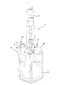
ステンレス鋼から成る撹拌装置としては、例えば特許文献1に記載されるようなものがある。撹拌装置1は、図6に示すように竪型円筒状の撹拌槽2を備えており、撹拌槽2の上方には、電動機3が設けられている。この電動機3には、そこから撹拌槽2内に向かって垂下する回動軸4が設けられ、回動軸4の下端には、アンカー翼5が配置されている。また、撹拌槽2は、その上面に立設された円筒状の供給管6及びマンホール7(ノズル)を有し、作業者が供給管6から液体やスラリーを投入し、またマンホール7から撹拌槽2内へと入れるようになっている。
As a stirring device made of stainless steel, there is one described in
特許文献1に記載の撹拌装置1では、マンホール7に撹拌処理中にマンホール7を閉じるべく蓋体9が設けられており、作業者10は、この蓋体9を開けることで撹拌槽2内を確認することができる。しかし、マンホール7のノズルネック7aが迫り出しているため、マンホール7から覗いたときの作業者10の視界は、ノズルネック7aにより一部遮られてしまう。それ故、確認できる範囲が狭く、作業者10は、姿勢を変えずに撹拌槽2内の各所を視認することができない。そのため、各所に存在する汚れ等を色々と姿勢を変えなければ確認することができず、作業者10にとって不便である。
In the stirring
このようにしてマンホール7から撹拌層2内を覗いたときに、撹拌層2の内壁に汚れ等があると、その汚れを落とすべく撹拌槽2内を洗浄する。撹拌槽2内を洗浄する際には、洗浄装置8が使用される。洗浄装置8は、棒状の支持部材を備え、その先端に洗浄ノズル8aが取り付けられている。作業者は、この洗浄装置8をマンホール7に挿入して前記支持部材を動かし、洗浄ノズル8aから噴射される洗浄液により洗浄を行う。撹拌槽2の上側の内壁を洗浄するためにマンホール7に挿入した洗浄装置8を徐々に水平方向へと倒していくと、やがて洗浄装置8がマンホール7の根元、即ちノズルネック7aに当たり、洗浄装置8をそれ以上の角度に倒すことができなくなる。
In this way, when the inside of the
ノズルネック7aは、マンホール7が竪型円筒状の槽本体2aの上面に溶接等によって接合されているため、槽本体2aの方に向かって迫り出すように角張っている。それ故、図6に示すように洗浄装置8を倒していくと、洗浄装置8が直ぐに当たってしまい、洗浄装置8をあまり傾けることができず、洗浄ノズル8aを撹拌槽2の上側の内壁に近づけることができない。そのため、上側の内壁に高圧の洗浄液を当てることができず、上側の内壁を上手く洗浄することができない。
The
このように、従来技術の撹拌槽1では、マンホール7等のノズルから中を覗いたときに一度に確認できる範囲が狭く、洗浄しにくい箇所が多い。
Thus, in the
そこで本発明は、ノズルから中を覗いたときに一度に確認できる範囲が広く、且つ洗浄しにくい箇所が少ない撹拌槽を提供することを目的としている。 Therefore, an object of the present invention is to provide an agitation tank that has a wide range that can be confirmed at a time when looking into the inside from a nozzle and has few places that are difficult to clean.
本発明の撹拌槽は、槽本体と、該槽本体に一体的に設けられるマンホールとを備え、低炭素ステンレス鋼から成る撹拌槽であって、前記マンホールは、引き抜き加工によって形成され、前記マンホールと前記槽本体とが繋がるノズルネックは、その裾が広がるように円弧状に湾曲するものである。 The stirring tank of the present invention includes a tank body and a manhole integrally provided in the tank body, and is a stirring tank made of low carbon stainless steel, the manhole being formed by drawing, and the manhole The nozzle neck connected to the tank main body is curved in an arc shape so that the skirt is widened.
本発明に従えば、ノズルネックを円弧状に湾曲されているので、従来技術の撹拌槽のノズルネックよりもノズルネックが容器外側に向けて引き上げられている。そのため、マンホールから撹拌槽内を覗いたときの視界が従来技術の撹拌槽よりも広い。それ故、マンホールから姿勢を変えることなく一度に確認できる範囲が広くなる。また、ノズルネックが容器外側に向けて引き上げられているので、洗浄する際にマンホールから挿入した洗浄装置等の洗浄部材を従来技術の撹拌槽よりも倒すことができる。それ故、従来技術の撹拌槽よりも様々な箇所に洗浄部材の先端、即ち洗浄ノズルを近づけることができるようになり、洗浄しにくい箇所を減らすことができる。 According to the present invention, since the nozzle neck is curved in an arc shape, the nozzle neck is raised toward the outside of the container rather than the nozzle neck of the conventional stirring tank. Therefore, the field of view when looking into the stirring tank from the manhole is wider than that of the conventional stirring tank. Therefore, the range that can be confirmed from the manhole without changing the posture is widened. Moreover, since the nozzle neck is pulled up toward the outer side of the container, the cleaning member such as a cleaning device inserted from the manhole can be tilted more than the conventional stirring tank when cleaning. Therefore, the tip of the cleaning member, that is, the cleaning nozzle can be brought closer to various places than the conventional agitation tank, and the number of places that are difficult to clean can be reduced.
また、本発明では、ノズルネックを円弧状に湾曲させて槽本体に一体的に設けている。このように円弧状に湾曲させたノズルネックを槽本体に一体的に設けるためには、例えば引き抜き加工等、加熱処理して塑性変形させる必要がある。この際、加熱処理時の温度及び加熱時間によりノズルネック近傍に鋭敏化が生じる。本発明の撹拌槽では、鋭敏化を生じにくい低炭素ステンレス鋼を用いることで、鋭敏化が生じることを抑制し、鋭敏化に伴う耐食性の低下を防いでいる。これにより、耐食性が要求される撹拌槽において、耐食性を維持しつつ洗浄性及び視認性を向上することが実現できる。 In the present invention, the nozzle neck is curved in an arc shape and provided integrally with the tank body. Thus, in order to integrally provide the nozzle neck curved in an arc shape in the tank body, it is necessary to perform plastic deformation by heat treatment such as drawing. At this time, sensitization occurs in the vicinity of the nozzle neck depending on the temperature and the heating time during the heat treatment. In the agitation tank of the present invention, by using low carbon stainless steel which does not easily cause sensitization, the occurrence of sensitization is suppressed, and the deterioration of corrosion resistance due to sensitization is prevented. As a result, it is possible to achieve improvement in cleanability and visibility while maintaining corrosion resistance in a stirring tank that requires corrosion resistance.
上記発明において、前記マンホールの内径は、300mm以上であり、前記ノズルネックの円弧の半径は、30mm以上100mm以下であることが好ましい。 In the above invention, the inner diameter of the manhole is preferably 300 mm or more, and the radius of the arc of the nozzle neck is preferably 30 mm or more and 100 mm or less.
上記構成に従えば、このマンホールを利用して作業員が出入りすることができる。この際、ノズルネックに鋭角な箇所がないため衣服の引っかかり等を無くすと共に、出入りの際に作業員がノズルネック部にぶつかった際に負傷することを抑制しうる。 If the said structure is followed, an operator can go in and out using this manhole. At this time, since there is no acute corner in the nozzle neck, it is possible to eliminate catching of clothes and the like, and it is possible to suppress injury when an operator hits the nozzle neck portion when entering and exiting.
上記発明において、前記槽本体の中には、回動軸と、該回動軸に着脱可能な羽根部材とを有する撹拌翼が配置され、前記槽本体には、前記回動軸が挿通する撹拌翼用ノズルが一体的に設けられ、前記撹拌翼用ノズルの内径は、前記回動軸の外径と略一致することが好ましい。 In the above invention, a stirring blade having a rotating shaft and a blade member detachably attached to the rotating shaft is disposed in the tank body, and the stirring shaft through which the rotating shaft is inserted is disposed in the tank body. It is preferable that the blade nozzle is integrally provided, and the inner diameter of the stirring blade nozzle is substantially equal to the outer diameter of the rotating shaft.
上記構成に従えば、羽根部材を着脱可能にすることで、撹拌翼用ノズルに回動軸を挿通した後に槽本体内で回動軸に羽根部材を取り付けることができ、内径が回動軸の外径と略一致する撹拌翼用ノズルであっても、撹拌翼を槽本体内に配置することができる。また、撹拌翼用ノズルの内径と回動軸の外径とが略一致するので、撹拌翼用ノズルと回動軸との間に形成される隙間をなくすことができ、撹拌翼用ノズルと回動軸との間にコンタミが入ることを防ぐことができる。また、撹拌翼用ノズルと回動軸との間に形成される隙間には洗浄液等が届きにくく、洗浄しにくい箇所が増えてしまう。撹拌翼用ノズルと回動軸との間に形成される隙間をなくすことにより、このような洗浄しにくい箇所を少なくすることができる。 According to the above configuration, by making the blade member detachable, the blade member can be attached to the rotation shaft in the tank body after the rotation shaft is inserted into the stirring blade nozzle, and the inner diameter is the rotation shaft. Even if the nozzle for the stirring blade substantially matches the outer diameter, the stirring blade can be disposed in the tank body. Further, since the inner diameter of the stirring blade nozzle and the outer diameter of the rotating shaft substantially coincide with each other, a gap formed between the stirring blade nozzle and the rotating shaft can be eliminated, and the stirring blade nozzle and the rotating shaft can be rotated. It is possible to prevent contamination from entering the moving shaft. In addition, the cleaning liquid or the like is difficult to reach the gap formed between the stirring blade nozzle and the rotating shaft, and the number of places where it is difficult to clean increases. By eliminating the gap formed between the stirring blade nozzle and the rotating shaft, it is possible to reduce such difficult-to-clean places.
上記発明において、槽上部に設けられる全てのノズルのノズルネックがその裾が広がるように円弧状に湾曲するものである。 In the said invention, the nozzle neck of all the nozzles provided in the tank upper part curves in the circular arc shape so that the skirt may spread.
上記構成に従えば、ノズルと槽本体との接続部分は円弧状に湾曲しているため、角張った箇所が無くなる。本発明にかかる撹拌槽では、ノズル部を通じて様々な機器を撹拌槽内に挿入したり内容物のサンプリングを行ったりするが、ノズル接続部分をなめらかな湾曲形状とすることで、挿入する機器が当該ノズル接続部分で引っかかったり又は破損することを抑制しうる。 If the said structure is followed, since the connection part of a nozzle and a tank main body is curving in circular arc shape, an angular part will disappear. In the agitation tank according to the present invention, various devices are inserted into the agitation tank or the contents are sampled through the nozzle portion, but by inserting the nozzle connection portion into a smooth curved shape, the device to be inserted is It is possible to prevent the nozzle connection portion from being caught or broken.
本発明の撹拌装置は、上述の撹拌槽と、前記撹拌翼と、前記撹拌翼の撹拌軸を回動駆動する回動駆動手段とを備えるものである。 The stirring device of the present invention includes the above-described stirring tank, the stirring blade, and a rotation driving unit that rotationally drives the stirring shaft of the stirring blade.
上記構成に従えば、上述のような撹拌槽を備え、その中に貯留される液体やスラリーを撹拌することができる撹拌槽値を実現することができる。 According to the said structure, the above stirring tanks are provided and the stirring tank value which can stir the liquid and slurry stored in it can be implement | achieved.
本発明によれば、ノズルから中を覗いたときに一度に確認できる範囲を広くし、且つ洗浄しにくい箇所を少なくすることができる。 According to the present invention, it is possible to widen the range that can be confirmed at a time when looking through the nozzle, and to reduce the number of places that are difficult to clean.
以下では、上述する図面を参照しつつ、本発明の実施形態である撹拌槽、及びそれを備える撹拌装置について説明する。 Below, the stirring tank which is embodiment of this invention, and a stirring apparatus provided with the same are demonstrated, referring drawings mentioned above.
<第1実施形態>
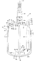
図1及び図2に示す第1実施形態の撹拌装置20は、化学工場等において、液体の混合、溶解、晶析、反応、濃縮及びスラリー懸濁等の撹拌処理を行なうために用いられる。撹拌装置20は、基本的に、撹拌槽21と、撹拌翼22と、回動駆動手段23と、バッフル24とを備える。
<First Embodiment>
The
撹拌槽21は、槽本体31を備える。槽本体31は、低炭素ステンレス鋼、例えばSUS304L、又はSUS316Lから成る竪型円筒形状の容器であり、液体やスラリーを貯留するようになっている。槽本体31の下面31a及び上面31bは、上下方向に夫々突出して湾曲する円弧状の皿形を有している。下面31aには、排出ノズル32が一体的に設けられ、排出ノズル32は、槽本体31内の液体やスラリーを排出するようになっている。また、排出ノズル32には、図示しないフラッシュ弁等を設け、液だまりのない構造とすることも可能であり、また、排出ノズル形状を座形式にすることで、タンクボール弁を選択しても良い。
The
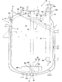
他方、槽本体31の上面31bには、図2に示すように3つのノズル33,34,35が一体的に設けられている。3つのノズル33,34,35は、撹拌翼用ノズル33、バッフル用ノズル34と、マンホール35であり、以下では、これら3つのノズル33,34,35について説明する。なお、本実施形態では、上面31bに図示しているノズルは上記の3つであるが、通常、これに原料投入ノズルが形成されている。形成されるノズルの数は特に限定されず、撹拌装置20の使用用途に合わせて5つ以上であってもよく、また3つであってもよい。
On the other hand, on the
撹拌翼用ノズル33は、円筒形状を有し、その軸線が槽本体31の軸線L1と一致するように配置されている。この撹拌翼用ノズル33には、撹拌翼22が挿通されている。撹拌翼22は、回動軸41と、羽根部材42とを有する。回動軸41は、円筒棒状の部材であり、その外径は、撹拌用ノズル33の内径と略一致している。ここで、本明細書において回動軸41の外径と撹拌用ノズル33の内径が略一致するとは、完全に一致することではなく、両者の隙間が数cm以下であることを意味する。回動軸41は、撹拌翼用ノズル33を挿通し、回動軸41と撹拌翼用ノズル33との間が封止部材(図示せず)により封止されている。なお、封止部材としてはメカニカルシール等を利用することができる。
The stirring
回動軸41の上端部41aは、撹拌翼用ノズル33から撹拌槽21の外方に突出しており、そこには、回動駆動手段23が連結されている。回動駆動手段23は、所謂電動機付減速機であり、撹拌槽21の上面31bに固定されており、回動軸41を回動するようになっている。
An
回動軸41の下端部41bは、撹拌槽21内に配置されており、そこには、羽根部材42が取り付けられている。羽根部材42は、取付部42aと2つの羽根構成部42bとを有する。取付部42aは、大略円筒状になっており、回動軸41の下端部41bにセットボルトより固定できるようになっている。なお、羽根はこのようなボス取り付けでも良いし、軸に直接溶接にて取り付けても構わない。
A
このように構成される撹拌翼22は、撹拌翼用ノズル33に回動軸41を挿通した後、撹拌槽21内で回動軸41に羽根部材42を取り付けることで、撹拌槽21内に配置される。このように配置された撹拌翼22には回動駆動手段23が取り付けられる。このようにして撹拌翼22に取り付けられた回動駆動手段23を駆動させて回動軸41を回転させることで羽根部材42が軸線L1を中心に回転し、2つの羽根構成部42bによって撹拌槽21に貯留される液体又はスラリーが回されて混合撹拌される。
The stirring
バッフル用ノズル34は、その軸線L2が槽本体31に平行な円筒形状を有しており、撹拌槽21の軸線L1から所定距離d1離れた位置に配置されている。このバッフル用ノズル34には、バッフル24が挿通している。バッフル24は、長尺のビーバーテイル状の棒部材であり、その上端部24a側にフランジ24cを有し、このフランジ24cがバッフル用ノズル34に固定されている。また、バッフル24の下端部24bには、温度計45が設けられている。この温度計45は、撹拌槽21の底面付近に配置されており、バッフル用ノズル34は、この温度計45が撹拌翼22の羽根部材42に当たらないように配置される。
The
このように配置されるバッフル24は、撹拌翼22により回される液体やスラリーの流動を阻害して乱す。これにより、撹拌槽21内に貯留される液体やスラリー全体をまんべんなく撹拌することができ、偏って撹拌されることを防いでいる。
The
マンホール35は、円筒形状を有しており、撹拌槽21の軸線L1から所定距離d2離れた位置に配置され、その軸線L3が槽本体31の上面31bのある点における接線と直交するようになっている。マンホール35は、洗浄又は点検において作業者等が撹拌槽21内に入ったり、液体等を投入したりするためのノズルであり、その内径φが例えば300mm以上であり、その高さhが例えば100mm以上になっている。また、マンホール35には、上側開口35bを塞ぐべく蓋体46が設けられている。
The
蓋体46は、大略的に円板形状になっている。蓋体46は、マンホール35に図示しない蝶番等を介して連結されており、上側開口35bを開閉することができるようになっている。蓋体46は、上側開口35bを閉じた状態でマンホール35のフランジ35cと共にクランプ部材47によりクランプされてマンホール35に固定されている。また、蓋体46は、覗き窓48が形成されており、この覗き窓48から撹拌槽21内を確認することができるようになっている。
The
このように槽本体31の上面31bに形成される撹拌翼用ノズル33、バッフル用ノズル34、及びマンホール35は、共に加熱処理(500℃〜1500℃で10分程度加熱)された槽本体31の上面31bを上方に向かって引き抜いて塑性加工する引き抜き加工によって形成される。撹拌翼用ノズル33は、槽本体31の軸線L1に沿って引き抜くことで形成され、その他のノズルは、軸線L1から所定距離d1離れた位置で引き抜くことで形成され、マンホール35は、軸線L1から所定距離d2離れた位置でその位置における法線方向に引き抜くことで形成される。
Thus, the stirring
このようにして形成された撹拌翼用ノズル33、バッフル用ノズル34、及びマンホール35は、槽本体31の上面31bに繋がるノズルネック33a,34a,35aを有し、各ノズルネック33a,34a,35aが裾に向かって広がるように円弧状に湾曲する。即ち、各ノズルネック33a,34a,35aがR面取りされたような形状になっている。以下では、このように形成されるバッフル用ノズル34及びマンホール35のノズルネック34a,35aが奏する効果について、図3及び4を参照しつつ説明する。
The stirring
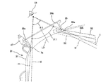
図3には、作業員51が蓋体46を外したマンホール35から撹拌槽21内を覗いたときの視界S1(2つの長破線l1の間の領域)を示している。また、図3には、従来技術のマンホール7のノズルネック7aのようにノズルネック7aが角張っている場合(2点鎖線で示す)における視界S2(2つの1点鎖線l2の間の領域)も示している。図4には、作業員51がマンホール35から撹拌槽21内を覗いたときに所定位置から覗ける角度範囲θ1(即ち、2つの長破線l1がなす角度であり、以下では、視界角度θ1ともいう)を示している。また、図4には、従来技術のマンホール7のノズルネック7aのようにノズルネック7aが角張っている場合の角度範囲θ2(即ち、2つの1点鎖線l2がなす角度であり、以下では、視界角度θ2ともいう)も示している。
FIG. 3 shows a field of view S <b> 1 (a region between two long broken lines 11) when the
撹拌槽21では、作業員51が蓋体46を開けてマンホール35から覗いて撹拌槽21内を確認するが、確認する際、作業員51の視界がマンホール35の壁面により一部遮られる。それ故、作業員51は、姿勢を変えながら撹拌槽21内を確認しなければならない。このように姿勢を変えながら撹拌槽21内を確認しなければならないのは、従来技術の撹拌装置1も同様である。しかし、マンホール35のノズルネック35aが従来技術の撹拌装置1のノズルネック7aよりも槽本体31の外側へと引き上げられているため、図3及び4から分かるように、その視界角度θ1が従来技術の撹拌装置1の視界角度θ2よりも大きく、その視界S1が従来技術の視界S2に比べて広くなっている。即ち、撹拌装置20と従来技術の撹拌装置1とで同じ位置からそれらの中を覗いた場合、一度で確認できる領域が従来技術の撹拌装置1より撹拌装置20の方が広くなっており、視認性が向上している。それ故、撹拌槽21内を確認する際、従来の場合に比べて、作業者はあまり姿勢を動かさなくとも撹拌槽21内を様々な箇所を確認することができ、撹拌槽21内の様々な箇所の汚れ等を確認することができる。
In the
このようにして汚れを確認した後、作業員51は、撹拌槽21内を図3及び4に示すような洗浄装置52により洗浄する。洗浄装置52は、例えばホース等に接続された長尺棒状の支持部材52aを有し、その先端部に洗浄ノズル52bが設けられている。この洗浄装置52をマンホール35から挿入し、洗浄ノズル52bから扇状に噴射される高圧の洗浄液を撹拌槽21の内壁に吹き付けることで撹拌槽21内を洗浄し、洗浄装置52の姿勢を変えて様々な箇所を洗浄することができるようになっている。
After confirming the contamination in this way, the
撹拌槽21の上側の内壁を洗浄するためには、洗浄装置52を水平方向に倒すように姿勢を変えるのだが、倒していくと、やがて洗浄装置52がノズルネック35aに当たる。撹拌槽21では、ノズルネック35aが裾に向かって広がるように円弧状に湾曲しているためノズルネック35aが引っ込んでおり、従来のようにノズルネック7aが迫り出している(図3の2点鎖線参照)場合に比べて、洗浄装置52を倒すことができる範囲が広くなる(図3の2点鎖線参照)。それ故、より撹拌槽21の上側の内壁に近づけることができ、より高圧の洗浄液を上面31bの内壁に吹き付けることができる。即ち、従来技術のように洗浄装置52では洗浄しにくかった撹拌槽2の上側の内壁であっても、撹拌槽21では、撹拌槽21の上側の内壁に近づけることができるようになり、従来の撹拌槽2より洗浄しやすくなっている。
In order to clean the inner wall on the upper side of the
また、図3に示すように、洗浄装置52を挿入してバッフル用ノズル34の中を洗浄する際、従来のようにノズルネック7a(2点鎖線参照)が迫り出していると、洗浄ノズル52bから噴射された洗浄液がノズルネック7aにより遮られ、バッフル用ノズル34内に洗浄液を送ることができなくなる。しかしながら、撹拌槽21のようにノズルネック34aが円弧状に湾曲していると、ノズルネック7aでは遮られていた洗浄液がバッフル用ノズル34の中まで達し、バッフル24のフランジ24cの領域Cまで洗浄液が届く。つまり、従来のノズルでは、届かなかった領域まで洗浄液が届くようになる。これにより、洗浄しにくい箇所を減らすことができる。
Further, as shown in FIG. 3, when the
このように3つのノズル33,34,35のノズルネック33a,34a,35aを円弧状に湾曲させることで、洗浄しにくい箇所を減らすことができ、また外方から覗いたときに確認できる範囲が広くすることができる。このような作用効果を奏するべくノズルネック33a,34a,35aを円弧状に湾曲して形成するためには、前述の通り引き抜き加工しなければならない。しかし、撹拌槽21に採用する鋼材によっては、引き抜き加工の加熱処理時の撹拌槽21の温度及び処理時間により鋭敏化が生じてしまう。鋭敏化は、撹拌槽21の耐食性を低下させてしまい、耐食性能を求められる撹拌槽21では、重要な問題である。
Thus, by curving the
そこで、撹拌槽21では、低炭素ステンレス鋼を採用すると共に加熱処理時間を短くし、成型時に撹拌槽21の鋭敏化が生じないようにしている。これにより、前述のような効果を達する撹拌槽21において、耐食性を維持することができる。
Therefore, in the stirring
このような構成を有する撹拌装置20では、撹拌翼用ノズル33の内径と回動軸41の外径とを一致させることで、それらの間に形成される隙間をなくしている。これにより、撹拌翼用ノズル33と回動軸41との間にコンタミが入ることを防ぐことができる。また、撹拌翼用ノズル33と回動軸41との間に形成される隙間には、洗浄液が届きにくく、またその隙間に入ったコンタミは、洗浄液でとりにくい。このように隙間が形成されることで洗浄しにくい箇所が増えてしまうが、この隙間を無くすことで洗浄しにくい箇所を減らして、洗浄性を向上させている。
In the stirring
また、ビーバーテイル状のバッフル24を採用することでも洗浄しにくい箇所を減らしている。というのも、バッフル24を撹拌槽21の内壁に接合する必要がなく、バッフル24と撹拌槽21の内壁との間に形成される小さな隙間や段差をなくすことができる。これら隙間や段差には洗浄装置52からの洗浄液が届きにくく、コンタミが隙間に入ったり、段差に付着したりすると、洗浄液でコンタミを取ることが難しくなる。このような洗浄しにくい隙間や段差をなくすことで、洗浄しにくい箇所を減らすことができる。
Further, by adopting the beaver tail-shaped
<第2実施形態>
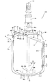
図5に示す第2実施形態の撹拌装置20Aは、第1実施形態の撹拌装置20と構成が類似している。そのため、第2実施形態の撹拌装置20Aの構成については、第1実施形態の撹拌装置20と同一の構成について同一の符号を付して説明を省略し、異なる構成についてだけ説明する。撹拌装置20Aは、バッフル板24Aを備えている。バッフル板24Aは、長尺矩形状の平板であり、撹拌槽21の内壁に軸線L1に向かって立設されている。バッフル板24Aは、上下方向に伸びており、その幅はバッフル24の内径より小さくなっているが、バッフル24と同様の撹拌性能を奏する。また、バッフル板24Aは、本実施形態では1つしか示していないが、複数のバッフル板24Aが撹拌槽21の内壁に周方向に間隔をあけて配置してもよい。
Second Embodiment
The stirring
このようにバッフル板24Aを設けた場合、作業者がマンホール35から撹拌槽21内を覗いたときにバッフル板24Aが邪魔にならないので、バッフル板24Aを外すことなく撹拌槽21内を見渡すことができるようになる。また、洗浄装置52を挿入したときにもバッフル板24Aが邪魔にならないので、バッフル板24Aを外すことなく撹拌槽21内をくまなく洗浄することができる。
When the
<その他の実施形態>
第1及び第2の実施形態の撹拌装置20,20Aにおいて、撹拌翼22は回動軸41と羽根部材42が分割できる構成となっているが、これに限定されず、回動軸41と羽根部材42が一体となったものでも良い。このとき、撹拌翼用ノズル33の内径と回動軸41の外径が略一致する場合、撹拌翼用ノズル33を通じて撹拌翼22を挿入することができないため、マンホール等を用いて撹拌翼22を撹拌槽21内に挿入し、その後、撹拌翼用ノズル33を通じて回動軸41を容器外に設置した回動駆動手段23と接続するようにすればよい。
<Other embodiments>
In the stirring
また、第1及び第2実施形態の撹拌装置20,20Aにおいて、槽本体31は、上面と側面とが一体成型された竪型円筒状になっているが、側面及び下面が断面U字状の円筒状に形成された筒状体とその開口部を開閉可能な蓋とを備えるものであってもよい。この場合、蓋に3つのノズル33,34,35が一体的に形成される。槽本体31をこのように構成することで、撹拌翼22の回動軸41と羽根部材42とが一体成型されていても槽本体31内に配置することができる。
Moreover, in the stirring
また、本実施形態において図示していないノズルについても、実施形態において説明したノズルと同様に全てのノズルネック部を湾曲した構造としても良い。全てのノズルのノズルネック部を円弧状に湾曲した構造とし、ノズルネック部分内面側の鋭角な角部を無くすことで、当該ノズルを利用して計測機器等を撹拌装置内に挿入し、又は設置又は取り出す際に当該計測機器等がノズルネック部分に接触して破損することを抑制しうる。 Further, the nozzles not shown in the present embodiment may have a structure in which all the nozzle neck portions are curved similarly to the nozzles described in the embodiments. The nozzle necks of all nozzles are curved in a circular arc shape, and by removing the sharp corners on the inner surface of the nozzle neck part, measuring instruments are inserted or installed in the stirring device using the nozzles. Or when taking out, it can suppress that the said measurement apparatus etc. contact a nozzle neck part, and are damaged.
また、本実施形態においては、容器内の洗浄のための容器内を洗浄する洗浄装置8をマンホール35を利用して外部から挿入する構成としたが、これに限定されず、撹拌槽2内を洗浄する洗浄ノズル8aを撹拌槽2内に設置した構成としてもよい。洗浄ノズル8aを撹拌槽2内に設置した場合、洗浄ノズル8a自体を移動させる自由度は低下するものの、本発明の撹拌槽はノズルネック部分を円弧状に湾曲した構成としているため、従来技術に比べ洗浄の死角となる箇所を狭くすることができるので、十分に容器内を洗浄することが可能となる。
In the present embodiment, the cleaning device 8 for cleaning the inside of the container for cleaning the inside of the container is configured to be inserted from the outside using the
なお、本発明は、実施の形態に限定されず、発明の趣旨を逸脱しない範囲で追加、削除、変更が可能である。 The present invention is not limited to the embodiments, and can be added, deleted, and changed without departing from the spirit of the invention.
以上のように、本発明は、液体の混合、溶解、晶析、反応、及びスラリー懸濁等を行なう撹拌処理において前記液体及びスラリーを貯めるための撹拌槽、及びそれを備える撹拌装置に適用することができる。 As described above, the present invention is applied to an agitation tank for storing the liquid and slurry in an agitation process for mixing, dissolving, crystallization, reaction, slurry suspension, and the like of a liquid, and an agitation apparatus including the agitation tank. be able to.
20 撹拌装置
20A 撹拌装置
21 撹拌槽
22 撹拌翼
23 回動駆動手段
24 バッフル
31 槽本体
33 撹拌翼用ノズル
33a ノズルネック
34 バッフル用ノズル
34a ノズルネック
35 マンホール
35a ノズルネック
41 回動軸
DESCRIPTION OF
Claims (5)
前記マンホールは、引き抜き加工によって形成され、
前記マンホールと前記槽本体とが繋がるノズルネックは、その裾が広がるように円弧状に湾曲することを特徴とする撹拌槽。 A tank body comprising a tank body and a manhole provided integrally with the tank body, the stirring tank made of low carbon stainless steel,
The manhole is formed by drawing,
The nozzle neck where the manhole and the tank main body are connected is curved in an arc shape so that the hem is widened.
前記ノズルネックの円弧の半径は、30mm以上100mm以下であることを特徴とする
請求項1に記載の撹拌槽。 The inner diameter of the manhole is 300 mm or more,
The stirring tank according to claim 1, wherein the radius of the arc of the nozzle neck is 30 mm or more and 100 mm or less .
前記槽本体には、前記回動軸が挿通する撹拌翼用ノズルが一体的に設けられ、
前記撹拌翼用ノズルの内径は、前記回動軸の外径と略一致することを特徴とする請求項1又は2に記載の撹拌槽。 In the tank body, a stirring blade having a rotating shaft and a blade member detachably attached to the rotating shaft is disposed,
The tank body is integrally provided with a stirring blade nozzle through which the rotating shaft is inserted,
The stirring tank according to claim 1 or 2, wherein an inner diameter of the stirring blade nozzle substantially coincides with an outer diameter of the rotating shaft.
前記撹拌翼と、
前記撹拌翼の撹拌軸を回動駆動する回動駆動手段とを備えることを特徴とする撹拌装置。 A stirring tank according to any one of claims 1 to 3,
The stirring blade;
A stirring device comprising: a rotation driving means for rotating the stirring shaft of the stirring blade.
Priority Applications (1)
| Application Number | Priority Date | Filing Date | Title |
|---|---|---|---|
| JP2009162967A JP5264635B2 (en) | 2009-07-09 | 2009-07-09 | Stirring tank and stirrer provided with the same |
Applications Claiming Priority (1)
| Application Number | Priority Date | Filing Date | Title |
|---|---|---|---|
| JP2009162967A JP5264635B2 (en) | 2009-07-09 | 2009-07-09 | Stirring tank and stirrer provided with the same |
Publications (2)
| Publication Number | Publication Date |
|---|---|
| JP2011016087A JP2011016087A (en) | 2011-01-27 |
| JP5264635B2 true JP5264635B2 (en) | 2013-08-14 |
Family
ID=43594301
Family Applications (1)
| Application Number | Title | Priority Date | Filing Date |
|---|---|---|---|
| JP2009162967A Active JP5264635B2 (en) | 2009-07-09 | 2009-07-09 | Stirring tank and stirrer provided with the same |
Country Status (1)
| Country | Link |
|---|---|
| JP (1) | JP5264635B2 (en) |
Families Citing this family (6)
| Publication number | Priority date | Publication date | Assignee | Title |
|---|---|---|---|---|
| JP5797121B2 (en) * | 2012-01-25 | 2015-10-21 | 三菱重工マシナリーテクノロジー株式会社 | Kneading rotor, kneading machine, and manufacturing method of kneading rotor |
| DE102013018094A1 (en) * | 2013-12-03 | 2015-06-03 | Merck Patent Gmbh | Mixing device and its use |
| JP6650221B2 (en) * | 2015-07-10 | 2020-02-19 | 佐竹化学機械工業株式会社 | Stirrer |
| JP6506682B2 (en) * | 2015-11-17 | 2019-04-24 | 株式会社神鋼環境ソリューション | Glass-lined opening / closing lid and glass-lined container comprising the same |
| JP6985879B2 (en) * | 2017-10-10 | 2021-12-22 | 株式会社神鋼環境ソリューション | Baffle plate for reaction tank |
| CN108579549A (en) * | 2018-06-28 | 2018-09-28 | 天津市弘亚润滑粉制造有限公司 | A kind of uniformly mixed powdered lubricant production mixing device |
Family Cites Families (5)
| Publication number | Priority date | Publication date | Assignee | Title |
|---|---|---|---|---|
| JPS54182981U (en) * | 1978-06-16 | 1979-12-25 | ||
| US4264215A (en) * | 1979-09-17 | 1981-04-28 | Sybron Corporation | Separable blade impeller |
| JP2749002B2 (en) * | 1992-01-31 | 1998-05-13 | 宇部興産株式会社 | High viscosity liquid stirring tank |
| JP3171704B2 (en) * | 1992-11-30 | 2001-06-04 | 池袋琺瑯工業株式会社 | Nozzle block assembly for glass lining equipment |
| JP2003033635A (en) * | 2001-05-17 | 2003-02-04 | Shinko Pantec Co Ltd | Stirring blade, stirring device and stirring method using the same |
-
2009
- 2009-07-09 JP JP2009162967A patent/JP5264635B2/en active Active
Also Published As
| Publication number | Publication date |
|---|---|
| JP2011016087A (en) | 2011-01-27 |
Similar Documents
| Publication | Publication Date | Title |
|---|---|---|
| JP5264635B2 (en) | Stirring tank and stirrer provided with the same | |
| CA2621588C (en) | Disposable sanitary mixing apparatus and method | |
| KR101892477B1 (en) | Concrete Mixer with cleaner for preventing stiffness | |
| JP7061512B2 (en) | Stirrer | |
| CN104736002A (en) | Ice dispensing and cleaning mechanism and process | |
| KR20180001238U (en) | Magnetic mixing apparatus | |
| JPH11319745A (en) | Stirrer | |
| JP2016112536A (en) | Mixer and operation method thereof | |
| KR102466361B1 (en) | Food source agitation system | |
| EP1693121B1 (en) | Cleanable mixer driver apparatus and method | |
| JP6506682B2 (en) | Glass-lined opening / closing lid and glass-lined container comprising the same | |
| JP2016013504A (en) | Fan washing jig and fan washing device | |
| JP2000266895A (en) | Cleaning equipment for solidifying material kneader for solidifying radioactive waste | |
| JP5511282B2 (en) | Stirrer | |
| US11174584B2 (en) | Integrated cap cleaner for a washing machine appliance | |
| JP2021053541A (en) | Cleaning device of cleaned object | |
| FI124015B (en) | Laundry system for kitchen utensils | |
| JP4553684B2 (en) | Cleaning device | |
| JP5808888B2 (en) | Stirring unit | |
| JP2012206459A (en) | Agitator vehicle and method of cleaning the same | |
| JP2000237567A (en) | Washer of powder agitator | |
| WO2007022398A2 (en) | Tripod-mounted magnetic mixer apparatus and method | |
| CN221542711U (en) | Milk tea barrel with automatic cleaning function | |
| JP7681541B2 (en) | Mixing Equipment | |
| JP3942954B2 (en) | Conical stirrer |
Legal Events
| Date | Code | Title | Description |
|---|---|---|---|
| A621 | Written request for application examination |
Free format text: JAPANESE INTERMEDIATE CODE: A621 Effective date: 20120131 |
|
| A977 | Report on retrieval |
Free format text: JAPANESE INTERMEDIATE CODE: A971007 Effective date: 20121225 |
|
| A131 | Notification of reasons for refusal |
Free format text: JAPANESE INTERMEDIATE CODE: A131 Effective date: 20130108 |
|
| A521 | Request for written amendment filed |
Free format text: JAPANESE INTERMEDIATE CODE: A523 Effective date: 20130305 |
|
| TRDD | Decision of grant or rejection written | ||
| A01 | Written decision to grant a patent or to grant a registration (utility model) |
Free format text: JAPANESE INTERMEDIATE CODE: A01 Effective date: 20130423 |
|
| A61 | First payment of annual fees (during grant procedure) |
Free format text: JAPANESE INTERMEDIATE CODE: A61 Effective date: 20130430 |
|
| R150 | Certificate of patent or registration of utility model |
Ref document number: 5264635 Country of ref document: JP Free format text: JAPANESE INTERMEDIATE CODE: R150 Free format text: JAPANESE INTERMEDIATE CODE: R150 |
|
| R250 | Receipt of annual fees |
Free format text: JAPANESE INTERMEDIATE CODE: R250 |
|
| R250 | Receipt of annual fees |
Free format text: JAPANESE INTERMEDIATE CODE: R250 |
|
| R250 | Receipt of annual fees |
Free format text: JAPANESE INTERMEDIATE CODE: R250 |
|
| R250 | Receipt of annual fees |
Free format text: JAPANESE INTERMEDIATE CODE: R250 |
|
| R250 | Receipt of annual fees |
Free format text: JAPANESE INTERMEDIATE CODE: R250 |
|
| R250 | Receipt of annual fees |
Free format text: JAPANESE INTERMEDIATE CODE: R250 |
|
| R250 | Receipt of annual fees |
Free format text: JAPANESE INTERMEDIATE CODE: R250 |
|
| R250 | Receipt of annual fees |
Free format text: JAPANESE INTERMEDIATE CODE: R250 |
|
| R250 | Receipt of annual fees |
Free format text: JAPANESE INTERMEDIATE CODE: R250 |