JP5260916B2 - Liquid crystal display - Google Patents
Liquid crystal display Download PDFInfo
- Publication number
- JP5260916B2 JP5260916B2 JP2007216619A JP2007216619A JP5260916B2 JP 5260916 B2 JP5260916 B2 JP 5260916B2 JP 2007216619 A JP2007216619 A JP 2007216619A JP 2007216619 A JP2007216619 A JP 2007216619A JP 5260916 B2 JP5260916 B2 JP 5260916B2
- Authority
- JP
- Japan
- Prior art keywords
- liquid crystal
- crystal display
- subdomain
- display device
- dividing unit
- Prior art date
- Legal status (The legal status is an assumption and is not a legal conclusion. Google has not performed a legal analysis and makes no representation as to the accuracy of the status listed.)
- Active
Links
Images


Classifications
-
- G—PHYSICS
- G02—OPTICS
- G02F—OPTICAL DEVICES OR ARRANGEMENTS FOR THE CONTROL OF LIGHT BY MODIFICATION OF THE OPTICAL PROPERTIES OF THE MEDIA OF THE ELEMENTS INVOLVED THEREIN; NON-LINEAR OPTICS; FREQUENCY-CHANGING OF LIGHT; OPTICAL LOGIC ELEMENTS; OPTICAL ANALOGUE/DIGITAL CONVERTERS
- G02F1/00—Devices or arrangements for the control of the intensity, colour, phase, polarisation or direction of light arriving from an independent light source, e.g. switching, gating or modulating; Non-linear optics
- G02F1/01—Devices or arrangements for the control of the intensity, colour, phase, polarisation or direction of light arriving from an independent light source, e.g. switching, gating or modulating; Non-linear optics for the control of the intensity, phase, polarisation or colour
- G02F1/13—Devices or arrangements for the control of the intensity, colour, phase, polarisation or direction of light arriving from an independent light source, e.g. switching, gating or modulating; Non-linear optics for the control of the intensity, phase, polarisation or colour based on liquid crystals, e.g. single liquid crystal display cells
- G02F1/133—Constructional arrangements; Operation of liquid crystal cells; Circuit arrangements
- G02F1/1333—Constructional arrangements; Manufacturing methods
- G02F1/1343—Electrodes
- G02F1/134309—Electrodes characterised by their geometrical arrangement
-
- G—PHYSICS
- G02—OPTICS
- G02F—OPTICAL DEVICES OR ARRANGEMENTS FOR THE CONTROL OF LIGHT BY MODIFICATION OF THE OPTICAL PROPERTIES OF THE MEDIA OF THE ELEMENTS INVOLVED THEREIN; NON-LINEAR OPTICS; FREQUENCY-CHANGING OF LIGHT; OPTICAL LOGIC ELEMENTS; OPTICAL ANALOGUE/DIGITAL CONVERTERS
- G02F1/00—Devices or arrangements for the control of the intensity, colour, phase, polarisation or direction of light arriving from an independent light source, e.g. switching, gating or modulating; Non-linear optics
- G02F1/01—Devices or arrangements for the control of the intensity, colour, phase, polarisation or direction of light arriving from an independent light source, e.g. switching, gating or modulating; Non-linear optics for the control of the intensity, phase, polarisation or colour
- G02F1/13—Devices or arrangements for the control of the intensity, colour, phase, polarisation or direction of light arriving from an independent light source, e.g. switching, gating or modulating; Non-linear optics for the control of the intensity, phase, polarisation or colour based on liquid crystals, e.g. single liquid crystal display cells
- G02F1/133—Constructional arrangements; Operation of liquid crystal cells; Circuit arrangements
- G02F1/1333—Constructional arrangements; Manufacturing methods
- G02F1/1343—Electrodes
-
- G—PHYSICS
- G02—OPTICS
- G02F—OPTICAL DEVICES OR ARRANGEMENTS FOR THE CONTROL OF LIGHT BY MODIFICATION OF THE OPTICAL PROPERTIES OF THE MEDIA OF THE ELEMENTS INVOLVED THEREIN; NON-LINEAR OPTICS; FREQUENCY-CHANGING OF LIGHT; OPTICAL LOGIC ELEMENTS; OPTICAL ANALOGUE/DIGITAL CONVERTERS
- G02F1/00—Devices or arrangements for the control of the intensity, colour, phase, polarisation or direction of light arriving from an independent light source, e.g. switching, gating or modulating; Non-linear optics
- G02F1/01—Devices or arrangements for the control of the intensity, colour, phase, polarisation or direction of light arriving from an independent light source, e.g. switching, gating or modulating; Non-linear optics for the control of the intensity, phase, polarisation or colour
- G02F1/13—Devices or arrangements for the control of the intensity, colour, phase, polarisation or direction of light arriving from an independent light source, e.g. switching, gating or modulating; Non-linear optics for the control of the intensity, phase, polarisation or colour based on liquid crystals, e.g. single liquid crystal display cells
- G02F1/137—Devices or arrangements for the control of the intensity, colour, phase, polarisation or direction of light arriving from an independent light source, e.g. switching, gating or modulating; Non-linear optics for the control of the intensity, phase, polarisation or colour based on liquid crystals, e.g. single liquid crystal display cells characterised by the electro-optical or magneto-optical effect, e.g. field-induced phase transition, orientation effect, guest-host interaction or dynamic scattering
- G02F1/139—Devices or arrangements for the control of the intensity, colour, phase, polarisation or direction of light arriving from an independent light source, e.g. switching, gating or modulating; Non-linear optics for the control of the intensity, phase, polarisation or colour based on liquid crystals, e.g. single liquid crystal display cells characterised by the electro-optical or magneto-optical effect, e.g. field-induced phase transition, orientation effect, guest-host interaction or dynamic scattering based on orientation effects in which the liquid crystal remains transparent
- G02F1/1393—Devices or arrangements for the control of the intensity, colour, phase, polarisation or direction of light arriving from an independent light source, e.g. switching, gating or modulating; Non-linear optics for the control of the intensity, phase, polarisation or colour based on liquid crystals, e.g. single liquid crystal display cells characterised by the electro-optical or magneto-optical effect, e.g. field-induced phase transition, orientation effect, guest-host interaction or dynamic scattering based on orientation effects in which the liquid crystal remains transparent the birefringence of the liquid crystal being electrically controlled, e.g. ECB-, DAP-, HAN-, PI-LC cells
-
- G—PHYSICS
- G02—OPTICS
- G02F—OPTICAL DEVICES OR ARRANGEMENTS FOR THE CONTROL OF LIGHT BY MODIFICATION OF THE OPTICAL PROPERTIES OF THE MEDIA OF THE ELEMENTS INVOLVED THEREIN; NON-LINEAR OPTICS; FREQUENCY-CHANGING OF LIGHT; OPTICAL LOGIC ELEMENTS; OPTICAL ANALOGUE/DIGITAL CONVERTERS
- G02F1/00—Devices or arrangements for the control of the intensity, colour, phase, polarisation or direction of light arriving from an independent light source, e.g. switching, gating or modulating; Non-linear optics
- G02F1/01—Devices or arrangements for the control of the intensity, colour, phase, polarisation or direction of light arriving from an independent light source, e.g. switching, gating or modulating; Non-linear optics for the control of the intensity, phase, polarisation or colour
- G02F1/13—Devices or arrangements for the control of the intensity, colour, phase, polarisation or direction of light arriving from an independent light source, e.g. switching, gating or modulating; Non-linear optics for the control of the intensity, phase, polarisation or colour based on liquid crystals, e.g. single liquid crystal display cells
- G02F1/133—Constructional arrangements; Operation of liquid crystal cells; Circuit arrangements
- G02F1/1333—Constructional arrangements; Manufacturing methods
- G02F1/1337—Surface-induced orientation of the liquid crystal molecules, e.g. by alignment layers
- G02F1/13373—Disclination line; Reverse tilt
-
- G—PHYSICS
- G02—OPTICS
- G02F—OPTICAL DEVICES OR ARRANGEMENTS FOR THE CONTROL OF LIGHT BY MODIFICATION OF THE OPTICAL PROPERTIES OF THE MEDIA OF THE ELEMENTS INVOLVED THEREIN; NON-LINEAR OPTICS; FREQUENCY-CHANGING OF LIGHT; OPTICAL LOGIC ELEMENTS; OPTICAL ANALOGUE/DIGITAL CONVERTERS
- G02F1/00—Devices or arrangements for the control of the intensity, colour, phase, polarisation or direction of light arriving from an independent light source, e.g. switching, gating or modulating; Non-linear optics
- G02F1/01—Devices or arrangements for the control of the intensity, colour, phase, polarisation or direction of light arriving from an independent light source, e.g. switching, gating or modulating; Non-linear optics for the control of the intensity, phase, polarisation or colour
- G02F1/13—Devices or arrangements for the control of the intensity, colour, phase, polarisation or direction of light arriving from an independent light source, e.g. switching, gating or modulating; Non-linear optics for the control of the intensity, phase, polarisation or colour based on liquid crystals, e.g. single liquid crystal display cells
- G02F1/133—Constructional arrangements; Operation of liquid crystal cells; Circuit arrangements
- G02F1/1333—Constructional arrangements; Manufacturing methods
- G02F1/1343—Electrodes
- G02F1/134309—Electrodes characterised by their geometrical arrangement
- G02F1/134345—Subdivided pixels, e.g. for grey scale or redundancy
Description
本発明は液晶表示装置に関し、特に透過率が向上した液晶表示装置に関する。 The present invention relates to a liquid crystal display device, and more particularly to a liquid crystal display device with improved transmittance.
一般に液晶表示装置は、薄膜トランジスタが形成されている第1基板と、第1基板に対向して配置されている第2基板と、これらの間に位置する液晶層とを含む。液晶表示装置において、PVA(patterned vertically aligned)モード及びMVA(multi−domain vertically aligned)モードは、視野角を改善するためのモードであって、VAモードの中で画素電極と共通電極とに切開パターンまたは突起が形成されたものを示す。これら切開パターンまたは突起によって形成される電界を利用して、液晶分子が傾く方向を調節することによって視野角が向上する。 In general, a liquid crystal display device includes a first substrate on which a thin film transistor is formed, a second substrate disposed to face the first substrate, and a liquid crystal layer positioned therebetween. In a liquid crystal display device, a patterned vertical aligned (PVA) mode and a multi-domain vertical aligned (MVA) mode are modes for improving a viewing angle, and an incision pattern is formed between a pixel electrode and a common electrode in the VA mode. Or the thing in which the protrusion was formed is shown. By using the electric field formed by these cutting patterns or protrusions, the viewing angle is improved by adjusting the direction in which the liquid crystal molecules are tilted.
しかし、切開パターンまたは突起の配置によっては、互いに異なる方向にばらばらに電界が形成される場合がある。この場合、ばらばらな方向に形成された電界の部分に位置した液晶は円滑に制御されないため、液晶層を通過する光の透過率を低下させるという問題がある。 However, depending on the dissection pattern or the arrangement of the protrusions, electric fields may be formed in different directions. In this case, the liquid crystal positioned in the portion of the electric field formed in different directions is not smoothly controlled, and there is a problem that the transmittance of light passing through the liquid crystal layer is lowered.
そこで、本発明の目的は、透過率が向上した液晶表示装置を提供することにある。 Therefore, an object of the present invention is to provide a liquid crystal display device with improved transmittance.
上記本発明の目的は、互いに絶縁されて交差するゲート線及びデータ線と、前記ゲート線及びデータ線に電気的に接続され、画素電極切開パターンが形成された画素電極とを含む第1基板と、第1基板に対向し、共通電極切開パターンが形成された共通電極を含む第2基板と、第1基板と第2基板との間に位置する液晶層とを含み、画素電極は、データ線の延長方向に沿って隣接し、互いに異なる方向に延長された第1領域と第2領域とを含み、画素電極及び共通電極のうちの少なくともいずれか一つには、第1領域と第2領域との間の境界領域から第1領域と第2領域のうちのいずれか一つに延長された補助切開パターンが形成された液晶表示装置によって達成される。 An object of the present invention is to provide a first substrate including a gate line and a data line which are insulated and intersect with each other, and a pixel electrode which is electrically connected to the gate line and the data line and has a pixel electrode cutting pattern formed thereon. A second substrate including a common electrode facing the first substrate and having a common electrode cutting pattern formed thereon, and a liquid crystal layer positioned between the first substrate and the second substrate, and the pixel electrode is a data line The first region and the second region are adjacent to each other along the extending direction of the first and second regions and extend in different directions, and at least one of the pixel electrode and the common electrode includes the first region and the second region. This is achieved by a liquid crystal display device in which an auxiliary incision pattern extending from the boundary region between the first region and the second region to any one of the first region and the second region is formed.
補助切開パターンは、第1領域に延長された第1部分と、第2領域に延長された第2部分とを含んでもよい。 The auxiliary incision pattern may include a first portion extended to the first region and a second portion extended to the second region.
第1部分の延長方向と第1領域の延長方向とは実質的に平行であり、第2部分の延長方向と第2領域の延長方向とは実質的に平行であってもよい。 The extension direction of the first portion and the extension direction of the first region may be substantially parallel, and the extension direction of the second portion and the extension direction of the second region may be substantially parallel.
第1領域の延長方向とゲート線と間の夾角は、第1部分の延長方向とゲート線との間の夾角より大きく、第2領域の延長方向とゲート線との間の夾角は、第2部分の延長方向とゲート線との間の夾角より大きくてもよい。 The depression angle between the extension direction of the first region and the gate line is larger than the depression angle between the extension direction of the first portion and the gate line, and the depression angle between the extension direction of the second region and the gate line is second. It may be larger than the included angle between the extending direction of the portion and the gate line.
補助切開パターンは、楔状であってもよい。 The auxiliary incision pattern may be wedge-shaped.
第1領域の延長方向とゲート線との間の夾角は約45度であり、第1領域の延長方向と第2領域の延長方向とは実質的に垂直であってもよい。 The depression angle between the extension direction of the first region and the gate line is about 45 degrees, and the extension direction of the first region and the extension direction of the second region may be substantially perpendicular.
補助切開パターンのうちの少なくとも一部は、画素電極切開パターンに接続されていてもよい。 At least a part of the auxiliary cut pattern may be connected to the pixel electrode cut pattern.
補助切開パターンのうちの少なくとも一部は、共通電極切開パターンに接続されていてもよい。 At least a part of the auxiliary incision pattern may be connected to the common electrode incision pattern.
補助切開パターンのデータ線の延長方向への長さは、5〜15μmであってもよい。 The length of the auxiliary incision pattern in the extension direction of the data line may be 5 to 15 μm.
補助切開パターンは、ゲート線の延長方向に沿って複数個備えられていてもよい。 A plurality of auxiliary incision patterns may be provided along the extending direction of the gate line.
液晶は、垂直配向モードであってもよい。 The liquid crystal may be in a vertical alignment mode.
画素電極は、データ線の延長方向に沿って1回折曲されていてもよい。 The pixel electrode may be bent once along the extending direction of the data line.
画素電極は、データ線の延長方向に沿って3回折曲されていてもよい。 The pixel electrode may be bent three times along the extension direction of the data line.
上記本発明の目的は、互いに絶縁交差するゲート線及びデータ線と、ゲート線及びデータ線に電気的に接続され、切開パターンが形成された画素電極とを含む第1基板と、第1基板に対向し、共通電極切開パターンが形成された共通電極を含む第2基板と、第1基板と第2基板との間に位置する液晶層とを含み、画素電極は、画素電極切開パターン及び共通電極切開パターンによって区切られた複数のサブドメインを含み、複数のサブドメインは、第1方向に位置する液晶方向子を有する第1サブドメインと、データ線の延長方向に沿って第1サブドメインと隣接し、第1方向と異なる第2方向に位置する液晶方向子を有する第2サブドメインとを含み、画素電極及び共通電極のうちの少なくともいずれか一つには、第1サブドメインと第2サブドメインとの間の境界領域から第1サブドメインと第2サブドメインのうちのいずれか一つに延長された補助切開パターンが形成された液晶表示装置によっても達成される。 An object of the present invention is to provide a first substrate including a gate line and a data line that are insulated from each other, a pixel electrode electrically connected to the gate line and the data line, and having a cut pattern formed thereon, and the first substrate. The pixel electrode includes a second substrate including a common electrode facing and having a common electrode cutting pattern formed thereon, and a liquid crystal layer positioned between the first substrate and the second substrate. The pixel electrode includes the pixel electrode cutting pattern and the common electrode. A plurality of subdomains separated by an incision pattern, the plurality of subdomains being adjacent to the first subdomain having a liquid crystal director located in the first direction and the first subdomain along the direction of extension of the data line And a second subdomain having a liquid crystal director positioned in a second direction different from the first direction, and at least one of the pixel electrode and the common electrode includes the first subdomain and the second subdomain. Also achieved by a liquid crystal display device from the boundary region sub cutting pattern extending to one of the first sub domain and the second sub-domains are formed between the subdomains.
補助切開パターンは、第1サブドメインに延長された第1部分と、第2サブドメインに延長された第2部分とを含んでもよい。 The auxiliary incision pattern may include a first portion extended to the first subdomain and a second portion extended to the second subdomain.
第1部分の延長方向と第1方向とは実質的に平行であり、第2部分の延長方向と第2方向とは実質的に平行であってもよい。 The extension direction of the first part and the first direction may be substantially parallel, and the extension direction of the second part and the second direction may be substantially parallel.
第1サブドメインの延長方向とゲート線と間の夾角は、第1部分の延長方向とゲート線との間の夾角より大きく、第2サブドメインの延長方向とゲート線との間の夾角は、第2部分の延長方向とゲート線との間の夾角より大きくてもよい。 The depression angle between the extension direction of the first subdomain and the gate line is larger than the depression angle between the extension direction of the first portion and the gate line, and the depression angle between the extension direction of the second subdomain and the gate line is: It may be larger than the included angle between the extending direction of the second portion and the gate line.
上記本発明の目的は、互いに絶縁交差するゲート線及びデータ線と、ゲート線及びデータ線に電気的に接続され、画素電極切開パターンが形成された画素電極を含む第1基板と、第1基板に対向し、共通電極切開パターンが形成された共通電極を含む第2基板と、第1基板と第2基板との間に位置する液晶層とを含み、画素電極は、第1領域と、第1領域から折曲延長された第2領域とを含み、画素電極及び共通電極のうちの少なくともいずれか一つには補助切開パターンが形成されており、補助切開パターンは、第1領域と第2領域との間の境界領域から第1領域に延長された第1部分と、境界領域から第2領域に延長された第2部分とを含む液晶表示装置によっても達成される。 SUMMARY OF THE INVENTION An object of the present invention is to provide a first substrate including a gate line and a data line that are insulated from each other, a pixel electrode electrically connected to the gate line and the data line, and having a pixel electrode cutting pattern formed thereon; And a liquid crystal layer positioned between the first substrate and the second substrate, the pixel electrode including the first region, the first substrate, and the second substrate. An auxiliary incision pattern is formed in at least one of the pixel electrode and the common electrode, and the auxiliary incision pattern includes the first area and the second area. It is also achieved by a liquid crystal display device including a first portion extending from the boundary region between the regions to the first region and a second portion extending from the boundary region to the second region.
上記本発明の目的は、互いに絶縁交差するゲート線及びデータ線と、ゲート線及びデータ線に電気的に接続された画素電極とを含む第1基板と、第1基板に対向し、共通電極を含む第2基板と、第1基板と第2基板との間に位置する液晶層とを含み、画素電極は、第1方向に位置する液晶方向子を有する第1サブドメインと、データ線の延長方向に沿って第1サブドメインと隣接し、第1方向と異なる第2方向に位置する液晶方向子を有する第2サブドメインとを含み、第1基板及び第2基板のうちの少なくともいずれか一つは、第1サブドメインと第2サブドメインとの境界領域から第1サブドメインと第2サブドメインのうちのいずれか一つに延長された補助ドメイン分割手段をさらに含む液晶表示装置によっても達成される。 An object of the present invention is to provide a first substrate including a gate line and a data line that are insulated from each other, and a pixel electrode electrically connected to the gate line and the data line, and a common electrode facing the first substrate. The pixel electrode includes a first sub-domain having a liquid crystal director positioned in the first direction, and an extension of the data line. The second sub-domain includes a liquid crystal layer positioned between the first substrate and the second substrate. And a second subdomain having a liquid crystal director positioned in a second direction different from the first direction and adjacent to the first subdomain along the direction, and at least one of the first substrate and the second substrate The liquid crystal display device further includes auxiliary domain dividing means extended from the boundary region between the first subdomain and the second subdomain to any one of the first subdomain and the second subdomain. Is done.
本発明によれば、透過率が向上した液晶表示装置が提供される。 According to the present invention, a liquid crystal display device with improved transmittance is provided.
以下、図面を参照しながら、本発明についてさらに詳細に説明する。以下において、ある膜(層)が他の膜(層)の「上部に」形成されて(位置して)いるということは、二つの膜(層)が接している場合だけでなく、二つの膜(層)の間に他の膜(層)が存在する場合も含む。 Hereinafter, the present invention will be described in more detail with reference to the drawings. In the following, a certain film (layer) is formed (positioned) `` on top '' of another film (layer) means that not only two films (layers) are in contact but also two This includes the case where another film (layer) exists between the films (layers).
図1は、本発明の第1実施形態による液晶表示装置1の一つの画素の等価回路図である。一つの画素は、二つのデータ線DL1、DL2に接続されており、二つの薄膜トランジスタT1、T2が備えられている。
FIG. 1 is an equivalent circuit diagram of one pixel of the liquid
第1薄膜トランジスタT1は、第1データ線DL1とゲート線GLとに接続され、第2薄膜トランジスタT2は、第2データ線DL2とゲート線GLとに接続される。 The first thin film transistor T1 is connected to the first data line DL1 and the gate line GL, and the second thin film transistor T2 is connected to the second data line DL2 and the gate line GL.
薄膜トランジスタT1、T2は、同一のゲート線GLに接続され、同時に駆動される。また、薄膜トランジスタT1、T2は、互いに異なるデータ線DL1、DL2に接続され、互いに異なるデータ電圧が印加される。 The thin film transistors T1 and T2 are connected to the same gate line GL and driven simultaneously. The thin film transistors T1 and T2 are connected to different data lines DL1 and DL2, and different data voltages are applied thereto.
各薄膜トランジスタT1、T2には、液晶キャパシタCLC1、CLC2と蓄積キャパシタCst1、Cst2とがそれぞれ接続される。液晶キャパシタCLC1、CLC2は、画素電極PE1と共通電極CEとの間及び画素電極PE2と共通電極CEとの間にそれぞれ形成され、蓄積キャパシタCst1、Cst2は、画素電極PE1と蓄積電極線SLとの間及び画素電極PE2と蓄積電極線SLとの間にそれぞれ形成される。ここで、第1画素電極PE1と第2画素電極PE2とは、互いに分離される。 Liquid crystal capacitors C LC1 and C LC2 and storage capacitors C st1 and C st2 are connected to the thin film transistors T1 and T2, respectively. The liquid crystal capacitors C LC1 and C LC2 are formed between the pixel electrode PE1 and the common electrode CE and between the pixel electrode PE2 and the common electrode CE, respectively, and the storage capacitors C st1 and C st2 are respectively connected to the pixel electrode PE1 and the storage electrode. They are formed between the line SL and between the pixel electrode PE2 and the storage electrode line SL. Here, the first pixel electrode PE1 and the second pixel electrode PE2 are separated from each other.
本発明による液晶表示装置においては、視認性が向上する。以下、その理由について説明する。 In the liquid crystal display device according to the present invention, the visibility is improved. The reason will be described below.
第1画素電極PE1には、第1薄膜トランジスタT1を通じて第1データ線DL1から第1データ電圧が印加され、第2画素電極PE2には、第2薄膜トランジスタT2を通じて第2データ線DL2から第1データ電圧とは異なる第2データ電圧が印加される。つまり、一つの画素内に互いに異なるデータ電圧が印加される二つのドメインが形成される。これによって、図2に示すように、第1画素電極PE1に対応し、輝度の高いハイドメインと、第2画素電極PE2に対応し、輝度の低いロードメインが形成される。このように一つの画素内にガンマカーブの異なる二つのドメインが存在する。これによって液晶表示装置の正面と側面との輝度及びカラーが互いに補償されて側面視認性が向上する。 The first data voltage is applied to the first pixel electrode PE1 from the first data line DL1 through the first thin film transistor T1, and the first data voltage is applied to the second pixel electrode PE2 from the second data line DL2 through the second thin film transistor T2. A second data voltage different from is applied. That is, two domains to which different data voltages are applied are formed in one pixel. As a result, as shown in FIG. 2, a high domain having a high luminance corresponding to the first pixel electrode PE1 and a low domain having a low luminance corresponding to the second pixel electrode PE2 are formed. Thus, there are two domains with different gamma curves in one pixel. As a result, the luminance and color of the front and side surfaces of the liquid crystal display device are compensated for each other, and the side visibility is improved.
図3乃至図6を参照しながら、第1実施形態による液晶表示装置について説明する。図5を参照すると、液晶表示装置1は、第1基板100、第1基板100に対向する第2基板200、及び両基板の間に位置する液晶層300を含む。
The liquid crystal display device according to the first embodiment will be described with reference to FIGS. Referring to FIG. 5, the liquid
図4は、第1基板100の画素電極161と、第2基板200の共通電極切開パターン252との配置関係を示すものである。
FIG. 4 shows an arrangement relationship between the
まず、図3及び図5を参照しながら、第1基板100について説明する。第1絶縁基板111の上にゲート配線が形成される。ゲート配線は、金属を含み単一層または多重層であってもよい。ゲート配線は、横方向に伸びるゲート線121、ゲート線121に接続されたゲート電極122a、122b、及びゲート線121と平行して延長され、画素の中心部を通る蓄積容量線123を含む。
First, the
第1絶縁基板111上において、シリコン窒化物(SiNx)などの絶縁物からなるゲート絶縁膜131が形成され、ゲート配線を覆っている。ゲート電極122a、122bに対応するゲート絶縁膜131上には、アモルファスシリコン又はポリシリコンなどの半導体からなる半導体層132が形成されており、半導体層132上には、シリサイドまたはn型不純物が高濃度にドープされたn+水素化アモルファスシリコンなどの物質で作られたオーミックコンタクト層133が形成される。第1ソース電極142aと第1ドレイン電極143aとの間のチャネル部ではオーミックコンタクト層133が除去される。
On the first insulating
オーミックコンタクト層133及びゲート絶縁膜131の上にはデータ配線が形成される。データ配線は、金属で形成された単一層または多重層であってもよい。データ配線は、縦方向に形成され、ゲート線121と交差して画素を形成する第1のデータ線141a、データ線141aの分岐でありオーミックコンタクト層133の上部まで延長される第1ソース電極142a、及び第1ソース電極142aと分離され、第1ソース電極142aの反対側のオーミックコンタクト層133の上部に形成される第1ドレイン電極143aを含む。第2ソース電極142bは、第2のデータ線141bから延び、オーミックコンタクト層(図示せず)の上部まで延長され、第2ドレイン電極143bは、第2ソース電極142bから分離され、第2ソース電極142bの反対側のオーミックコンタクト層(図示せず)上に形成される。
A data wiring is formed on the
ゲート電極122a、ソース電極142a、及びドレイン電極143aは第1薄膜トランジスタT1の構成要素であり、ゲート電極122b、ソース電極142b、及びドレイン電極143bは第2薄膜トランジスタT2の構成要素である。
The
データ線141は、第1データ線141aと第2データ線141bとを含む。第1薄膜トランジスタT1は、画素の右側を通る第1データ線141aに接続され、第2薄膜トランジスタT2は、画素の左側を通る第2データ線141bに接続される。
The
データ配線及びデータ線に覆われない半導体層132の上には、シリコン窒化物などの絶縁物からなる保護膜151が形成される。
A
保護膜151の上には、有機膜152が形成される。有機膜152は、厚さがゲート絶縁膜131及び保護膜151に比べて大きく、スピンコーティング、スリットコーティング、スクリーンプリンティングなどの方法によって形成されてもよい。有機膜152は、BCB(benzocycloubutene)系列、オレフィン系列、アクリル樹脂(acrylic resin)系列、ポリイミド(polyimide)系列、フッ素樹脂のうちのいずれか一つであってもよい。
An
有機膜152には、第1ドレイン電極143a及び第2ドレイン電極143bを露出させる第1コンタクトホール171a及び第2コンタクトホール171bと、蓄積容量線123に対応し、保護膜151を露出させる開口部172、(図6参照)とが形成される。第1及び第2コンタクトホール171a、171bでは保護膜151も共に除去される。
In the
図6に示すように、画素電極161は、開口部172を通じて蓄積容量線123と近く位置し、画素電極161と蓄積容量線123との間には有機膜152が存在しない。画素電圧が伝達される画素電極161と共通電圧が印加される蓄積容量線123との間で蓄積容量Cstが形成される。
As shown in FIG. 6, the
蓄積容量線123の上に開口部172を形成し、有機膜152を除去する理由は、有機膜152は、厚さが大きく、誘電率が小さいため、画素電極161と蓄積容量線123との間に蓄積容量を形成し難いためである。
The reason why the
再び図3及び図5を参照すれば、有機膜152の上には画素電極161が形成される。画素電極161は、通常、ITO(indium tin oxide)またはIZO(indium zinc oxide)などの透明な導電物質からなる。
Referring to FIGS. 3 and 5 again, the
画素電極161は、第1及び第2データ線141a、141bの延長方向に沿って延長され、3回折曲される。画素電極161は、全体的に上下対称の形状であってもよい。蓄積電極線123は、中間に位置した画素電極161の折曲部分を通る。
The
画素電極161は、第1画素電極切開パターン162によって互いに分離された第1画素電極161aと第2画素電極161bとを含む。第2画素電極161bは、楔状であり、画素の中央に位置する。第1画素電極161aは、第1画素電極161bを取り囲んでおり、第1画素電極161aは第2画素電極161bより広い面積を有する。
The
図3に示すように、蓄積容量線123は、第2画素電極161bより第1画素電極161aとさらに広い部分でオーバーラップ(重畳)する。これは、面積の大きい第1画素電極161aに該当するドメインが、大きい蓄積容量Cstを要するためである。
As shown in FIG. 3, the
再び図3及び図5を参照すれば、第1画素電極161aと第2画素電極161bとには第2画素電極切開パターン163が形成される。第2画素電極切開パターン163のうちの一部は、第1画素電極切開パターン162と平行に配置され、他の一部はゲート線121と平行に配置される。
Referring to FIGS. 3 and 5 again, a second pixel
第1画素電極161aは、第1コンタクトホール171aを通じて第1薄膜トランジスタT1のドレイン電極143aと接続され、第2画素電極161bは、第2コンタクトホール171bを通じて第2薄膜トランジスタT2のドレイン電極143bと接続される。
The
画素電極切開パターン162、163は、後述する共通電極切開パターン252と共に、液晶層300を多数のサブドメインに分割する。本発明におけるサブドメインは、画素電極161の周縁と切開パターン162、163、252によって取り囲まれた領域であって、大部分が斜め方向に延長される。図4には、複数のサブドメインのうちの第1サブドメイン(斜線を引いた領域)と第2サブドメイン(点で表示した領域)とが示される。第1サブドメインと第2サブドメインとは第1及び第2データ線141a、141bの延長方向に互いに隣接し、延長方向は約90度をなす。
The pixel
再び図3を参照すれば、画素電極161の折曲部分のうちの上部と下部に位置する折曲部分に第1補助切開パターン164が形成される。第1補助切開パターン164は切開パターン162、163に接続され、第1及び第2データ線141a、141bの延長方向に沿って配置される。
Referring to FIG. 3 again, the first
次に、図4及び図5を参照しながら、第2基板200について説明する。第2絶縁基板211の上にブラックマトリックス221が形成される。ブラックマトリックス221は、通常、黒色顔料が添加された感光性有機物質からなる。前記黒色顔料としては、カーボンブラックやチタンオキサイドなどを用いる。
Next, the
第2絶縁層211とブラックマトリックス221との上部には、カラーフィルタ231が形成される。カラーフィルタ231は、互いに異なる色相、例えば、赤色、緑色及び青色のサブ層を含んでもよい。
A
カラーフィルタ231の上には、オーバーコート膜241が形成される。オーバーコート膜241は、第2基板200を平坦化する。オーバーコート膜241は省略してもよい。
An
オーバーコート膜241の上部には、共通電極251が形成される。共通電極251は、ITO(indium tin oxide)またはIZO(indium zinc oxide)などの透明な導電物質からなる。共通電極251は、第1基板100の画素電極161と共に液晶層300に直接電圧を印加し、電界を生成する。
A
共通電極251には、共通電極切開パターン252と第2補助切開パターン253とが形成される。図4に示すように、共通電極切開パターン252の一部は、第1画素電極切開パターン162と平行に延長されており、他の部分はゲート線121と平行に延長される。
In the
第2補助切開パターン253は、共通電極切開パターン252に接続されており、画素電極161の折曲部分の上部領域と下部領域とに対応して形成される。第2補助切開パターン253は、データ線141の延長方向に沿って配置される。上記パターン162、163、252は、上述の実施形態に限定されず、多様な形状に形成できる。
The second
図5に示すように、第1基板100と第2基板200との間に液晶層300が位置する。液晶層300はVA(vertically aligned)モードであって、液晶分子は、電圧の加えられない状態では長手方向が垂直になるように配置される。電圧が加えられると、液晶分子は誘電率異方性が負であるので、電界に対して垂直方向に傾く。ところが、上記切開パターン162、163、252が形成されていなければ、電界がばらばらな方向に形成されるところでは、液晶分子は傾く方向が決定されないため、多くの方向に無秩序に配列されるようになり、液晶分子の配向方向の異なる境界面で回位線(disclination line)が生じる。
As shown in FIG. 5, the
以上のパターン162、163、252は、液晶層300に電界は形成されるとき、フリンジエレクトリックフィールド(fringe electric field)を作って液晶配向の方向を決定する。
The
以上、説明した液晶表示装置1においては、補助切開パターン164、253によって開口率が向上する。開口率の向上について図7を参照しながら説明し、共通電極251に形成された第2補助切開パターン253を例に挙げて説明する。
In the liquid
第1サブドメインは第1方向に延長され、第2サブドメインは第2方向に延長される。実施形態において、第1方向と第2方向とは直角をなし、第1方向とゲート線121との夾角θ1は約45度である。両サブドメインの間には折曲領域(境界領域)が位置する。
The first subdomain is extended in the first direction, and the second subdomain is extended in the second direction. In the embodiment, the first direction and the second direction are perpendicular to each other, and the included angle θ1 between the first direction and the
第2補助切開パターン253は、折曲領域(境界領域)から第1サブドメインに延長された第1部分253aと、折曲領域から第2サブドメインに延長された第2部分253bとを含む。第1部分253aは、第1方向と平行に延長され、第2部分253bは第2方向と平行に延長される。つまり、第1部分253aとゲート線121との夾角θ2も約45度であり、第1部分253aと第2部分253bとの延長方向は垂直をなす。
The second
第1サブドメインに位置する液晶層300の液晶方向子は、大部分が第1方向と平行になるように配列し、第2サブドメインに位置する液晶層300の液晶方向子は、大部分が第2方向と平行になるように配列する。
Most of the liquid crystal directors of the
第1サブドメインと第2サブドメインとが接する境界領域では互いに垂直をなす液晶方向子(director)が衝突する。図面において、液晶層300を、第1方向または第2方向に液晶方向子が配列された正常液晶層300aと、液晶方向子が第1方向及び第2方向とは異なる方向に配列された非正常液晶層300bとに分けて表示した。
In the boundary region where the first subdomain and the second subdomain are in contact with each other, liquid crystal directors that are perpendicular to each other collide with each other. In the drawing, the
非正常液晶層300bは、境界領域でゲート線121に対してほぼ垂直方向の液晶方向子を有する。非正常液晶層300bはさらにランダムに傾いた液晶を含むので、回位線を誘発して表示品質を低下させる。
The abnormal
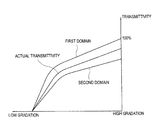
また、液晶層300は、液晶方向子が水平方向と45度の角度をなすときに最高の透過率を示すが(一対の偏光軸のうちのいずれか一つは水平方向であり、他の一つは垂直方向の場合)、非正常液晶層300bの液晶方向子が45度より大きい場合、透過率が低下する。
In addition, the
第2補助切開パターン253は、境界領域の付近でさらなる電界を形成して、非正常液晶層300bが形成される領域を最小化する。これによって、回位線の発生領域Bの幅d1が減少して透過率が向上する。
The second
第2補助切開パターン253を形成する場合、回位線の発生領域の幅は約10μmになり、第2補助切開パターン253の長さd2は5μm〜15μmであってもよい。これに限定されないが、第2補助切開パターン253の間の間隔d3は5.5μm〜7.6μm、第2補助切開パターン253の幅d4は3μm〜5μmであってもよい。画素電極161に形成された第1補助切開パターン164の間隔d5は、第2補助切開パターン253の間の間隔d3の100%〜130%、第1補助切開パターン164の幅d6は、第2補助切開パターン253の幅d4の70%〜100%であってもよいが、これに限定されない。
When the second
以上、説明した切開パターン162、163、252及び補助切開パターン164、253は、液晶層300を複数のドメインに分けるドメイン分割手段である。ドメイン分割手段は第1実施形態の切開パターンに限定されず、これを第2実施形態を通じて説明する。
As described above, the
図8を参照しながら、第2実施形態について説明する。図8は、図3のV−V線による断面図である。 The second embodiment will be described with reference to FIG. 8 is a cross-sectional view taken along line VV in FIG.
図8に示されるように、共通電極251はパターニングされておらず、第1実施形態の共通電極切開パターン252に対応する位置には突部255が形成される。突部255は、有機物からなることができ、共通電極切開パターン252と同様に、画素電極切開パターン162、163と共に液晶層300を多数のサブドメインに分割する。
As shown in FIG. 8, the
図示していないが、第1実施形態において、第2補助切開パターン253の代わりに補助突起が共通電極251上に形成されてもよい。他の実施形態においては、第1実施形態の第1補助切開パターン164に対応する位置に補助突起を形成してもよい。
Although not shown, in the first embodiment, auxiliary protrusions may be formed on the
図9を参照しながら、第3実施形態について説明する。第1補助切開パターン164の間には第2補助切開パターン253が形成され、第2補助切開パターン253の間には第1補助切開パターン164が形成される。
The third embodiment will be described with reference to FIG. A second
第3実施形態によれば、補助切開パターン164、253が緻密になれば、回位線の誘発領域Bの幅をさらに減らすことができる。他の実施形態において、第1補助切開パターン164と第2補助切開パターン253とは一部又は完全にオーバーラップ(重畳)するように形成してもよい。
According to the third embodiment, if the
図10を参照しながら、第4実施形態について説明する。第4実施形態によれば、共通電極251には、共通電極切開パターン252の外に別途の切開パターンは形成されない。代わりに、第1実施形態の第2補助切開パターン253に対応する位置には、第1補助切開パターン164が備えられる。他の実施形態において、画素電極161には第1補助切開パターン164が形成されず、共通電極251のみに第2補助切開パターン253が形成されてもよい。
The fourth embodiment will be described with reference to FIG. According to the fourth embodiment, a separate incision pattern is not formed on the
図11を参照しながら、本発明の第5実施形態について説明する。第5実施形態においては、第1補助切開パターン164は、第2画素電極切開パターン163から分離され、第2補助切開パターン253は共通電極切開パターン252から分離される。
A fifth embodiment of the present invention will be described with reference to FIG. In the fifth embodiment, the first
図12を参照しながら、本発明の第6実施形態について説明する。第6の実施形態においては、補助切開パターン164、253は、ゲート線121との間の夾角が小さく備えられる。つまり、第2補助切開パターン253とゲート線121との夾角θ3は45度より小さい。
A sixth embodiment of the present invention will be described with reference to FIG. In the sixth embodiment, the
第6実施形態によれば、補助切開パターン164、253が形成する電界が非正常液晶層300bの液晶方向子に及ぶ影響が大きくなり、回位線の形成領域Bをさらに縮小させることができる。夾角θ3は、25度〜40度であってもよい。
According to the sixth embodiment, the influence of the electric field formed by the
図13を参照しながら、本発明の第7実施形態について説明する。画素電極161は全体的に楔状であり、データ線141の延長方向に沿って1回折曲される。画素電極161は、互いに分離されている第1画素電極161aと第2画素電極161bとを含む。
A seventh embodiment of the present invention will be described with reference to FIG. The
補助切開パターン400は、折曲部に、ゲート線121の延長方向に沿って形成される。また、補助切開パターン400は、データ線141の方向に延長されてもよい。補助切開パターン400は、画素電極161および/または共通電極251に形成されてもよい。
The
図14を参照しながら、本発明の第8実施形態について説明する。画素電極161は、全体的に長方形の形状であり、互いに分離されている第1画素電極161aと第2画素電極161bとを含む。
The eighth embodiment of the present invention will be described with reference to FIG. The
画素電極161は、全体的には長方形の形状であるが、切開パターン162、163に電界の方向が衝突する領域を有する。補助切開パターン400は、電界の方向が衝突する領域に形成される。
The
図15を参照しながら、第9実施形態について説明する。画素電極161は、全体的に楔状であり、データ線141の延長方向に沿って1回折曲されている。切開パターンは図示されていないが、画素電極161の全体が接続される。補助切開パターン400は、折曲部に、ゲート線121の延長方向に沿って形成される。また、補助切開パターン400は、データ線141の方向に形成されてもよい。
The ninth embodiment will be described with reference to FIG. The
図16を参照しながら、第10実施形態について説明する。画素電極161は、データ線141の延長方向に沿って3回折曲される。切開パターンは図示されていないが、画素電極161の全体が接続される。補助切開パターン400は、折曲部に、ゲート線121の延長方向に沿って形成される。また、補助切開パターン400は、データ線141の方向に形成されてもよい。
The tenth embodiment will be described with reference to FIG. The
以上、本発明のいくつかの実施形態が図示されて説明されたが、本発明が属する技術分野の通常の知識を有する当業者であれば、本発明の原則や精神から逸脱せずに本実施形態を変形できることが分かる。本発明の範囲は、請求項とその均等物によって決められなければならない。 Although several embodiments of the present invention have been illustrated and described above, those skilled in the art having ordinary knowledge in the technical field to which the present invention pertains may carry out the present invention without departing from the principles and spirit of the present invention. It can be seen that the form can be modified. The scope of the invention should be determined by the claims and their equivalents.
121 ゲート線
141 データ線
152 有機膜
161 画素電極
162 第1画素電極切開パターン
163 第2画素電極切開パターン
251 共通電極
252 共通電極切開パターン
164、253、400 補助切開パターン
121
Claims (13)
前記第1基板に対向し、第2ドメイン分割手段を含む共通電極を含む第2基板と、
前記第1基板と前記第2基板との間に配置され、垂直配向モードの液晶層と、
を具備し、
前記画素領域は、前記第1ドメイン分割手段及び前記第2ドメイン分割手段により分割されるサブドメインを含み、
前記サブドメインは、電圧印加時、第1方向に配置された液晶方向子を有する第1サブドメインと、電圧印加時、前記第1方向とは異なる第2方向に配置された液晶方向子を有する第2サブドメインとを含み、
前記第2サブドメインと前記第1サブドメインとは、前記第1ドメイン分割手段の境界部または前記第2ドメイン分割手段の境界部により分割され、
前記画素電極と前記共通電極のうちの少なくとも1つは、少なくとも一つの補助切開パターンを含み、
前記補助切開パターンは、前記第1ドメイン分割手段の前記境界部、または前記第2ドメイン分割手段の前記境界部に連結され、前記境界部から前記第1サブドメインと前記第2サブドメインに向いて延びており、
且つ、前記補助切開パターンは、前記第1ドメイン分割手段と前記第2ドメイン分割手段との間で前記第1ドメイン分割手段と前記第2ドメイン分割手段との延長方向と平行に延長されていることを特徴とする液晶表示装置。 A first substrate including a gate line and a data line that are insulated from each other; and a pixel electrode that is electrically connected to the gate line and the data line and disposed in a pixel region and includes a first domain dividing unit;
A second substrate including a common electrode facing the first substrate and including second domain dividing means;
A vertical alignment mode liquid crystal layer disposed between the first substrate and the second substrate;
Comprising
The pixel region includes a subdomain divided by the first domain dividing unit and the second domain dividing unit,
The subdomain has a first subdomain having a liquid crystal director disposed in a first direction when a voltage is applied, and a liquid crystal director disposed in a second direction different from the first direction when a voltage is applied. A second subdomain,
The second subdomain and the first subdomain are divided by a boundary part of the first domain dividing unit or a boundary part of the second domain dividing unit,
At least one of the pixel electrode and the common electrode includes at least one auxiliary incision pattern;
The auxiliary incision pattern is connected to the boundary part of the first domain dividing unit or the boundary part of the second domain dividing unit, and extends from the boundary part to the first subdomain and the second subdomain. Extended,
The auxiliary incision pattern is extended between the first domain dividing unit and the second domain dividing unit in parallel with the extending direction of the first domain dividing unit and the second domain dividing unit. A liquid crystal display device.
Applications Claiming Priority (2)
| Application Number | Priority Date | Filing Date | Title |
|---|---|---|---|
| KR10-2007-0033731 | 2007-04-05 | ||
| KR1020070033731A KR101393634B1 (en) | 2007-04-05 | 2007-04-05 | Liquid crystal display device |
Publications (3)
| Publication Number | Publication Date |
|---|---|
| JP2008257163A JP2008257163A (en) | 2008-10-23 |
| JP2008257163A5 JP2008257163A5 (en) | 2010-10-07 |
| JP5260916B2 true JP5260916B2 (en) | 2013-08-14 |
Family
ID=39415126
Family Applications (1)
| Application Number | Title | Priority Date | Filing Date |
|---|---|---|---|
| JP2007216619A Active JP5260916B2 (en) | 2007-04-05 | 2007-08-23 | Liquid crystal display |
Country Status (4)
| Country | Link |
|---|---|
| US (1) | US8081282B2 (en) |
| EP (1) | EP1978401B1 (en) |
| JP (1) | JP5260916B2 (en) |
| KR (1) | KR101393634B1 (en) |
Families Citing this family (6)
| Publication number | Priority date | Publication date | Assignee | Title |
|---|---|---|---|---|
| JP4828557B2 (en) * | 2008-03-04 | 2011-11-30 | 株式会社 日立ディスプレイズ | Liquid crystal display |
| KR101298424B1 (en) * | 2008-12-08 | 2013-08-20 | 엘지디스플레이 주식회사 | Liquid crystal display of fringe field switching type |
| KR101668380B1 (en) * | 2009-05-19 | 2016-10-24 | 삼성디스플레이 주식회사 | Liquid crsytal display |
| EP2669882B1 (en) * | 2012-05-31 | 2019-10-09 | Samsung Display Co., Ltd. | Display device and driving method thereof |
| CN108806506A (en) | 2017-05-05 | 2018-11-13 | 元太科技工业股份有限公司 | switch element array structure |
| CN109285451B (en) | 2017-07-21 | 2021-05-11 | 元太科技工业股份有限公司 | Pixel array substrate |
Family Cites Families (22)
| Publication number | Priority date | Publication date | Assignee | Title |
|---|---|---|---|---|
| US6977704B2 (en) | 2001-03-30 | 2005-12-20 | Fujitsu Display Technologies Corporation | Liquid crystal display |
| JP5041629B2 (en) | 2001-06-06 | 2012-10-03 | 奇美電子股▲ふん▼有限公司 | Liquid crystal display |
| JP4172750B2 (en) | 2001-12-26 | 2008-10-29 | 東芝松下ディスプレイテクノロジー株式会社 | Liquid crystal display |
| JP4076768B2 (en) * | 2001-12-26 | 2008-04-16 | 東芝松下ディスプレイテクノロジー株式会社 | Liquid crystal display |
| KR101337260B1 (en) | 2003-08-13 | 2013-12-05 | 삼성디스플레이 주식회사 | Multi-domain liquid crystal display and a thin film transistor substrate of the same |
| KR20050077571A (en) | 2004-01-28 | 2005-08-03 | 삼성전자주식회사 | Multi-domain liquid crystal display |
| KR20050100959A (en) | 2004-04-16 | 2005-10-20 | 삼성전자주식회사 | Array substrate, manufacturing method thereof, and display device having the same |
| JP2005316331A (en) | 2004-04-30 | 2005-11-10 | Toshiba Matsushita Display Technology Co Ltd | Liquid crystal display device |
| KR20060018401A (en) | 2004-08-24 | 2006-03-02 | 삼성전자주식회사 | Multi-domain liquid crystal display |
| TWI261712B (en) | 2004-09-30 | 2006-09-11 | Chi Mei Optoelectronics Corp | Liquid crystal display |
| JP4604645B2 (en) | 2004-10-22 | 2011-01-05 | セイコーエプソン株式会社 | Liquid crystal display device and electronic device |
| JP4454487B2 (en) | 2004-12-17 | 2010-04-21 | シャープ株式会社 | Liquid crystal display |
| KR20060077896A (en) | 2004-12-31 | 2006-07-05 | 엘지.필립스 엘시디 주식회사 | Multi-domain liquid crystal display device and the fabrication method thereof |
| JP4738000B2 (en) * | 2005-01-19 | 2011-08-03 | シャープ株式会社 | Liquid crystal display |
| KR101133761B1 (en) * | 2005-01-26 | 2012-04-09 | 삼성전자주식회사 | Liquid crystal display |
| KR101137858B1 (en) | 2005-03-16 | 2012-04-20 | 엘지디스플레이 주식회사 | In-plane switching mode liquid crystal display device |
| KR20060111771A (en) | 2005-04-25 | 2006-10-30 | 삼성전자주식회사 | Liquid crystal display apparatus |
| KR20060116580A (en) | 2005-05-10 | 2006-11-15 | 삼성전자주식회사 | Liquid crystal display |
| TWI330735B (en) * | 2005-07-11 | 2010-09-21 | Chi Mei Optoelectronics Corp | Multi-domain vertical alignment lcd |
| KR101171180B1 (en) * | 2005-07-15 | 2012-08-20 | 삼성전자주식회사 | Liquid crystal display |
| KR101230304B1 (en) * | 2005-09-07 | 2013-02-06 | 삼성디스플레이 주식회사 | Liquid crystal display |
| KR20070035224A (en) | 2005-09-27 | 2007-03-30 | 삼성전자주식회사 | Liquid crystal display |
-
2007
- 2007-04-05 KR KR1020070033731A patent/KR101393634B1/en active IP Right Grant
- 2007-08-23 JP JP2007216619A patent/JP5260916B2/en active Active
- 2007-12-04 US US11/950,304 patent/US8081282B2/en active Active
-
2008
- 2008-03-22 EP EP08005417A patent/EP1978401B1/en active Active
Also Published As
| Publication number | Publication date |
|---|---|
| KR20080090649A (en) | 2008-10-09 |
| US8081282B2 (en) | 2011-12-20 |
| JP2008257163A (en) | 2008-10-23 |
| EP1978401B1 (en) | 2011-06-15 |
| KR101393634B1 (en) | 2014-05-12 |
| US20080246908A1 (en) | 2008-10-09 |
| EP1978401A1 (en) | 2008-10-08 |
Similar Documents
| Publication | Publication Date | Title |
|---|---|---|
| KR101327795B1 (en) | Liquid crystal display device | |
| JP4316381B2 (en) | High aperture ratio LCD | |
| JP4815584B2 (en) | Liquid crystal display device and thin film transistor display panel used therefor | |
| KR101293950B1 (en) | Display substrate and display panel having the same | |
| KR101237011B1 (en) | Liquid crystal display | |
| KR101300184B1 (en) | Liquid crystal display | |
| JP2007047784A (en) | Liquid crystal display | |
| KR20110120624A (en) | Array substrate for in-plane switching mode lcd | |
| JP5260916B2 (en) | Liquid crystal display | |
| KR20080030244A (en) | Liquid crystal display | |
| US7929099B2 (en) | Liquid crystal display with improved lateral visibility | |
| KR20070042824A (en) | Liquid crystal display | |
| KR101430623B1 (en) | Liquid crystal display device | |
| KR20120130582A (en) | An array substrate for In-Plane switching mode LCD | |
| JP2007316643A (en) | Liquid crystal display device | |
| KR20080046042A (en) | Display panel | |
| KR102211598B1 (en) | Liquid crystal display | |
| JP2004258652A (en) | Liquid crystal display | |
| JP5016404B2 (en) | Display substrate and display panel having the same | |
| KR20160095700A (en) | Liquid crystal display | |
| KR20140037688A (en) | Fringe field switching liquid crystal display device and method of fabricating the same | |
| KR101794283B1 (en) | Thin film transtistor array panel and liquid crystal display | |
| KR20090005817A (en) | Display substrate and display panel having the same | |
| KR101282402B1 (en) | Liquid crystal display device | |
| KR20080022355A (en) | Liquid crystal display device |
Legal Events
| Date | Code | Title | Description |
|---|---|---|---|
| A521 | Request for written amendment filed |
Free format text: JAPANESE INTERMEDIATE CODE: A821 Effective date: 20080704 |
|
| A521 | Request for written amendment filed |
Free format text: JAPANESE INTERMEDIATE CODE: A523 Effective date: 20081017 |
|
| A521 | Request for written amendment filed |
Free format text: JAPANESE INTERMEDIATE CODE: A523 Effective date: 20090518 |
|
| A521 | Request for written amendment filed |
Free format text: JAPANESE INTERMEDIATE CODE: A821 Effective date: 20090520 |
|
| A521 | Request for written amendment filed |
Free format text: JAPANESE INTERMEDIATE CODE: A523 Effective date: 20100820 |
|
| A621 | Written request for application examination |
Free format text: JAPANESE INTERMEDIATE CODE: A621 Effective date: 20100820 |
|
| A521 | Request for written amendment filed |
Free format text: JAPANESE INTERMEDIATE CODE: A523 Effective date: 20110728 |
|
| A977 | Report on retrieval |
Free format text: JAPANESE INTERMEDIATE CODE: A971007 Effective date: 20120518 |
|
| A131 | Notification of reasons for refusal |
Free format text: JAPANESE INTERMEDIATE CODE: A131 Effective date: 20120605 |
|
| A521 | Request for written amendment filed |
Free format text: JAPANESE INTERMEDIATE CODE: A523 Effective date: 20120905 |
|
| A131 | Notification of reasons for refusal |
Free format text: JAPANESE INTERMEDIATE CODE: A131 Effective date: 20121120 |
|
| A711 | Notification of change in applicant |
Free format text: JAPANESE INTERMEDIATE CODE: A712 Effective date: 20121213 |
|
| A521 | Request for written amendment filed |
Free format text: JAPANESE INTERMEDIATE CODE: A523 Effective date: 20130219 |
|
| TRDD | Decision of grant or rejection written | ||
| A01 | Written decision to grant a patent or to grant a registration (utility model) |
Free format text: JAPANESE INTERMEDIATE CODE: A01 Effective date: 20130409 |
|
| A61 | First payment of annual fees (during grant procedure) |
Free format text: JAPANESE INTERMEDIATE CODE: A61 Effective date: 20130426 |
|
| FPAY | Renewal fee payment (event date is renewal date of database) |
Free format text: PAYMENT UNTIL: 20160502 Year of fee payment: 3 |
|
| R150 | Certificate of patent or registration of utility model |
Ref document number: 5260916 Country of ref document: JP Free format text: JAPANESE INTERMEDIATE CODE: R150 Free format text: JAPANESE INTERMEDIATE CODE: R150 |
|
| R250 | Receipt of annual fees |
Free format text: JAPANESE INTERMEDIATE CODE: R250 |
|
| R250 | Receipt of annual fees |
Free format text: JAPANESE INTERMEDIATE CODE: R250 |
|
| R250 | Receipt of annual fees |
Free format text: JAPANESE INTERMEDIATE CODE: R250 |
|
| R250 | Receipt of annual fees |
Free format text: JAPANESE INTERMEDIATE CODE: R250 |
|
| R250 | Receipt of annual fees |
Free format text: JAPANESE INTERMEDIATE CODE: R250 |
|
| R250 | Receipt of annual fees |
Free format text: JAPANESE INTERMEDIATE CODE: R250 |
|
| R250 | Receipt of annual fees |
Free format text: JAPANESE INTERMEDIATE CODE: R250 |
|
| S531 | Written request for registration of change of domicile |
Free format text: JAPANESE INTERMEDIATE CODE: R313531 |
|
| R350 | Written notification of registration of transfer |
Free format text: JAPANESE INTERMEDIATE CODE: R350 |
|
| RD02 | Notification of acceptance of power of attorney |
Free format text: JAPANESE INTERMEDIATE CODE: R3D02 |
|
| R250 | Receipt of annual fees |
Free format text: JAPANESE INTERMEDIATE CODE: R250 |