JP5260369B2 - Distributed system - Google Patents
Distributed system Download PDFInfo
- Publication number
- JP5260369B2 JP5260369B2 JP2009067237A JP2009067237A JP5260369B2 JP 5260369 B2 JP5260369 B2 JP 5260369B2 JP 2009067237 A JP2009067237 A JP 2009067237A JP 2009067237 A JP2009067237 A JP 2009067237A JP 5260369 B2 JP5260369 B2 JP 5260369B2
- Authority
- JP
- Japan
- Prior art keywords
- state
- node
- system state
- nodes
- ecu
- Prior art date
- Legal status (The legal status is an assumption and is not a legal conclusion. Google has not performed a legal analysis and makes no representation as to the accuracy of the status listed.)
- Active
Links
Images


Abstract
Description
本発明は、ネットワークにより結合された複数の装置が協調動作して、高信頼な制御を行うシステムに関する。 The present invention relates to a system in which a plurality of devices connected by a network perform a cooperative operation to perform highly reliable control.
近年、自動車の運転快適性や安全性の向上を目指して、機械的な操作力の伝達ではなく、電子制御により、運転者のアクセル,ステアリング,ブレーキなどの操作を車両の駆動力,操舵力,制動力発生機構などに反映させる車両制御システムの開発が行われている。建機など他の機器でも同様な電子制御の適用が進められている。これらシステムでは、機器に分散配置した複数の電子制御装置(ECU、Electronic Control Unit)がネットワークを介してデータを送受信し協調動作を行う。この際、同一ネットワーク内のあるECUに障害が発生した際に、各ECUが障害発生箇所を正確に特定し、障害内容に応じた適切なバックアップ制御を行うことが、フェールセーフ上必要不可欠となる。上記課題を解決するために、ECUが相互に各ノードの状態(障害有無など)を監視して判定し、その判定結果を交換した上で、多数決などにより各ノード状態を特定し、ノード間で状態認識を高信頼に一致化する技術がある(特許文献1参照)。ノードの障害有無は各ノードの属性の1つであるが、ノードに属さないシステムとしての状態に関する認識一致化も、同様にして行うことができる。 In recent years, with the aim of improving the driving comfort and safety of automobiles, the driver's accelerator, steering, brake, and other operations can be controlled by electronic control instead of mechanical operation force transmission. Development of a vehicle control system to be reflected in a braking force generation mechanism or the like has been performed. Similar electronic control is being applied to other equipment such as construction machinery. In these systems, a plurality of electronic control units (ECU, Electronic Control Unit) distributed and arranged in equipment perform data transmission / reception via a network and perform cooperative operation. At this time, when a failure occurs in a certain ECU in the same network, it is indispensable for fail-safe that each ECU accurately identifies the location of the failure and performs appropriate backup control according to the content of the failure. . In order to solve the above problems, the ECUs mutually monitor and determine the state of each node (such as the presence or absence of a failure), and after exchanging the determination results, identify each node state by a majority vote or the like. There is a technique for matching state recognition with high reliability (see Patent Document 1). The presence / absence of a failure of a node is one of the attributes of each node, but recognition matching regarding a state as a system that does not belong to the node can be similarly performed.
特許文献1では、ノード状態の認識および認識一致化機能を、ミドルウェアに実装することにより、当該機能を汎用化するとしている。しかし、ノードやシステムの状態遷移はシステムにより多種多様であり、状態遷移が複雑なシステムで詳細なノード状態やシステム状態の認識一致化を図ろうとすると、ノード状態の判定方法をシステムごとに適合させる必要が生じる場合が考えられ、その際の当該ミドルウェアのソフトウェア変更量が大きくなる可能性もある。
In
また、ノードの取りうる状態は複数あり、各ノードはその中から真の状態を1つ抽出して正しく認識しなければならない。例えばあるノードがデータを送信してこないときの当該ノードの状態として、一旦正常に起動したがその後故障した場合、未起動であるがこれから起動する予定である場合、起動不可である場合、仕様通りスリープ状態に入っている場合などがある。これらのうちどれが真の状態であるかは自動的には決まらず、他ノードがあるルールを持って判断する必要がある。しかし各ノードの置かれた条件は同じではないので、同じルールに従ってもノード間で判断に差が出る可能性がある。つまりあるノードに関する状態認識には、各ノードの主観的な判断が入る場合があるといえる。このような場合でもノード間で状態認識を一致化させる仕組みが必要である。また、ノード状態が主要な決定要因となるシステムとしての状態についても、同様のことがいえる。 There are a plurality of states that a node can take, and each node must extract one true state and recognize it correctly. For example, when a node does not send data, the status of the node once started normally but then fails, if it has not started but is scheduled to start in the future, cannot be started, There is a case where it is in a sleep state. Which of these is true is not automatically determined, and it is necessary to determine with a rule that other nodes have. However, since the conditions under which each node is placed are not the same, there is a possibility that judgments may differ between nodes even if the same rules are followed. That is, it can be said that the state recognition regarding a certain node may involve subjective judgment of each node. Even in such a case, a mechanism for matching the state recognition between the nodes is necessary. The same can be said for the state of the system in which the node state is a major determinant.
詳細なノード状態やシステム状態は、各ノードの障害有無(正常または異常)といった基本的なノード状態を入力として判定される場合が多い。このような基本的なノード状態は、システムの種類に依らず幅広く有効な概念であり、その認識方法は、データ受信時における異常検出や、自己診断ならびにその通知など、多様なシステムにて共通的な手法である。 The detailed node state and system state are often determined by inputting a basic node state such as the presence or absence (normal or abnormal) of each node. Such a basic node state is a concept that is widely effective regardless of the type of system, and its recognition method is common to various systems such as anomaly detection during data reception, self-diagnosis and its notification. It is a technique.
このため、基本的なノード状態認識に関わる機能と、詳細なノード状態やシステム状態の認識に関わる機能とを分離して備え、機能間のインターフェースを定義することにより、システムに応じて変更が必要な部分は後者の一部に限定することが可能である。これにより、システムごとに変更する機能を少なくし、変更の不要な機能を多くすることでシステム間で機能の共有化ができ、当該ミドルウェア(もしくはハードウェア回路)の再利用性が向上する。また、詳細なノード状態やシステム状態の認識に関わる機能を柔軟に設定できるので、ノードの主観的な判断の余地を含む、複雑な状態遷移を取り扱うことができる。 For this reason, the functions related to basic node status recognition and the functions related to detailed node status and system status recognition are separated, and the interface between functions must be defined to change according to the system. This part can be limited to the latter part. As a result, by reducing the functions to be changed for each system and increasing the functions that do not need to be changed, the functions can be shared between the systems, and the reusability of the middleware (or hardware circuit) is improved. In addition, since functions relating to detailed node state and system state recognition can be set flexibly, complex state transitions including room for subjective judgment of nodes can be handled.
請求項および以降の説明では、上記の基本的なノード状態を単に「ノード状態」と呼び、ノード詳細状態やシステム状態のことを合わせて「システム状態」と呼ぶ。 In the claims and the following description, the above basic node state is simply referred to as “node state”, and the node detailed state and system state are collectively referred to as “system state”.
多様で複雑な遷移を取りうるシステム状態に関して、ノード間の状態認識を高信頼に一致化することができる。また、システム状態の認識および認識一致化機能を提供するミドルウェアやハードウェアの再利用性を高めつつ、柔軟で拡張性のある構成とすることができる。 Regarding system states that can take various and complicated transitions, state recognition between nodes can be made highly reliable. In addition, it is possible to provide a flexible and expandable configuration while improving the reusability of middleware and hardware that provide system state recognition and recognition matching functions.
ノード状態とシステム状態とは各々で認識一致化されるが、システム状態の判定にノード間で認識一致化された後のノード状態を入力として利用する方法では、システム状態の認識一致化がロバストになり、より高信頼化される。 The node state and the system state are recognized and matched with each other. However, in the method of using the node state after the recognition and matching between the nodes for the determination of the system state as an input, the recognition and matching of the system state is robust. And higher reliability.
本発明の実施形態を図面を用いて説明する。 Embodiments of the present invention will be described with reference to the drawings.
図1は、本発明の一実施例をなす分散システムの一般化された構成図である。分散システムは、複数のノード10(10−1,10―2,…,10−n)からなり、これらのノードはネットワーク100を介して接続される。ここで、ノードとは、ネットワークを介して情報通信可能な処理装置であり、CPUを含む各種の電子制御装置,アクチュエータとその制御部,センサなどが含まれる。ECUはノードの一種である。ネットワーク100は多重通信可能な通信ネットワークであり、あるノードから当該ネットワークに接続された他の全てのノードに対して、同一内容を同時に送信するブロードキャスト送信が可能である。通信プロトコルとしては、FlexRayやTTCAN(time-triggered CAN)などを用いることができる。
FIG. 1 is a generalized configuration diagram of a distributed system according to an embodiment of the present invention. The distributed system includes a plurality of nodes 10 (10-1, 10-2,..., 10-n), and these nodes are connected via a
各ノードx(xはノード番号、x=1〜n)は、CPU11−x,主メモリ12−x,I/F13−x、及び、記憶装置14−xとからなり、これらは内部通信線などにより接続されている。又、I/F13−xは、ネットワーク100と接続されている。
Each node x (x is a node number, x = 1 to n) includes a CPU 11-x, a main memory 12-x, an I / F 13-x, and a storage device 14-x, which are internal communication lines and the like. Connected by. The I / F 13-x is connected to the
記憶装置14−xは、ノード状態判定部15−x,ノード状態交換部16−x,ノード状態特定部17−x,システム状態判定部18−x,システム状態交換部19−x及び、システム状態特定部20−xなどのプログラムを格納する。 The storage device 14-x includes a node state determination unit 15-x, a node state exchange unit 16-x, a node state identification unit 17-x, a system state determination unit 18-x, a system state exchange unit 19-x, and a system state. A program such as the specifying unit 20-x is stored.
CPU11−xは、これらのプログラムを主メモリ12−xに読み込み、実行することにより、処理を行う。本稿で説明するプログラムやデータは、予め記憶装置に格納しておいてもよいし、ネットワーク経由で他の装置からダウンロードしてもよい。又、当該プログラムにより実現される機能を、専用のハードウェアにより実現してもよい。以下では、プログラムを主体として記載するが、実際の主体はCPUである。 The CPU 11-x performs processing by reading these programs into the main memory 12-x and executing them. The programs and data described in this article may be stored in advance in a storage device, or may be downloaded from another device via a network. Further, the function realized by the program may be realized by dedicated hardware. In the following, the program is described as a subject, but the actual subject is a CPU.
ノード状態判定部15−xは、各ノードに対しノード状態を監視し判定する(以下、MON1)。ノード状態交換部16−xは、ネットワーク100を介し、ノード状態判定部15−xが判定したノード状態をノード間で送受信し、ノード状態に関する各ノードの判定結果を集約する(以下、EXD1)。ノード状態特定部17−xは、ノード状態交換部16−xが集約したノード状態判定結果に基づき、多数決処理などによりノード状態特定(以下、ID1)を行い、ノード間でノード状態の認識を一致化する。本発明では、各ノードにより判定され集約された判定結果から1つの結論を確定し、ノード間で一致した結果を得ることを「特定」と表す。
The node state determination unit 15-x monitors and determines the node state for each node (hereinafter, MON1). The node state exchange unit 16-x transmits and receives the node state determined by the node state determination unit 15-x via the
ノード状態判定(MON1)の具体的な手段の例としては、データ受信時にプロトコル異常を検出したとき、送信ノードの異常と判定する方法がある。また、受信データの誤り検出符合やシリアル番号の未更新によりエラーが検出された際に、送信ノードの異常と判定する方法がある。また自ノードの異常に関しては、自己診断機能により検出可能である。自己診断結果を他ノードに送信した場合には、受信ノードが送信ノードの異常を検出できる。 As a specific example of the node state determination (MON1), there is a method of determining a transmission node abnormality when a protocol abnormality is detected during data reception. In addition, there is a method of determining that the transmission node is abnormal when an error is detected due to an error detection code of received data or an unupdated serial number. Further, the abnormality of the own node can be detected by the self-diagnosis function. When the self-diagnosis result is transmitted to another node, the receiving node can detect the abnormality of the transmitting node.
システム状態判定部18−xは、システム状態判定(以下、MON2)を行う。ここで「システム状態」とは前述の通り、ノードに属さないシステムとしての状態であるが、ノードの詳細状態も含むとする。システム状態交換部19−xは、ネットワーク100を介し、システム状態判定部18−xが判定したシステム状態をノード間で送受信し、システム状態に関する各ノードの判定結果を集約する(以下、EXD2)。システム状態特定部20−xは、システム状態交換部19−xが集約したシステム状態判定結果に基づき、多数決処理などによりシステム状態特定(以下、ID2)を行い、ノード間でシステム状態の認識を一致化する。
The system state determination unit 18-x performs system state determination (hereinafter, MON2). Here, as described above, the “system state” is a state as a system that does not belong to a node, but also includes a detailed state of the node. The system state exchanging unit 19-x transmits and receives the system state determined by the system state determining unit 18-x via the
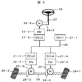
図2は本実施例の対象システムである、ステアバイワイヤの概略構成を示している。システムはECU1〜4(21−1〜4)の4ノード構成であり、各ECUはネットワーク25で接続されている。ECU2〜4はそれぞれインバータ22−2〜4を持ち、モータ23−2〜4を制御している。モータ23−2は駆動力伝達機構24−2を介してハンドル26,シャフト27に反力を与える。モータ23−3〜4は、それぞれ駆動力伝達機構24−3〜4を介してラック28を制御し、車輪29−1〜2の方向を変えることで転舵する。ECU2は、運転手によるハンドル26の操作量をシャフト27に備えたセンサから検出し、ネットワーク25に送信する。ECU3〜4は、車輪29−1〜2の軸に備えたセンサから転舵角を検出し、ネットワーク25に送信する。ECU1はネットワーク25を介してハンドル操作量や転舵角を取得し、インバータ22−2〜4を介するモータ23−2〜4の制御内容を計算する。計算値は制御指令として、ネットワーク25を介してECU2〜4に送信する。ECU2〜4はECU1からの制御指令に基づき、モータ23−2〜4を制御する。
FIG. 2 shows a schematic configuration of steer-by-wire, which is the target system of this embodiment. The system has a four-node configuration of
図3はシステム状態特定の処理フローである。このフロー中の処理は、各ノードがネットワーク100を介して相互に通信し同期を取って進められる。
FIG. 3 is a processing flow for specifying the system state. The processing in this flow proceeds in synchronization with each node communicating with each other via the
まずステップ31にてノード状態判定部15−xは、各ノードについての状態を自ノード単独で判定する(MON1)。ノード状態判定(MON1)結果は、各ノードに関する障害有無である。障害の項目は複数設定してもよい。
First, in
次にステップ32にてシステム状態判定部18−xは、ステップ31で得られたノード状態判定結果を入力すなわち判断材料の1つとし、システム状態を自ノード単独で判定する(MON2)。
Next, in
次にステップ33にてノード状態交換部16−xは、ステップ31で得られたノード状態判定結果を、I/F13−xを利用して各ノード間で交換する(EXD1)。各ノードは、自ノードを含む各ノードによる、各ノードに対する状態判定(MON1)結果を集約し保持することになる。同様に、システム状態交換部19−xは、ステップ33で得られたシステム状態判定結果を、I/F13−xを利用して各ノード間で交換する(EXD2)。各ノードは、自ノードを含む各ノードによる、システム状態判定(MON2)結果を集約し保持することになる。
Next, in
次にステップ34にて、ノード状態特定部17−xは、ステップ33で各ノードに集約されたノード状態判定結果から、多数決処理などにより各ノードの状態を特定する(ID1)。同様に、システム状態特定部20−xは、ステップ33で各ノードに集約されたシステム状態判定結果から、多数決処理などによりシステム状態を特定する(ID2)。
Next, in
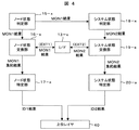
図4は、図3の処理フローを実施した場合のデータフローである。上位レイヤ40は、制御アプリケーションなどのソフトウェアが該当する。上位レイヤ40に対し、ノード状態特定部17−xによるノード状態特定(ID1)結果と、システム状態特定部20−xによるシステム状態特定(ID2)結果とは、API(Application Program Interface)などのインターフェースを介して提供される。ノード状態判定部15−xによるノード状態判定(MON1)結果や、システム状態判定部18−xによるシステム状態判定(MON2)結果を、上位レイヤ40に提供しても良い。
FIG. 4 is a data flow when the processing flow of FIG. 3 is performed. The
ノード状態やシステム状態の認識は、ノード状態特定結果やシステム状態特定結果をもとになされる。この状態遷移の管理は、ノード状態特定部17−xやシステム状態特定部20−xで行っても良いが、上位レイヤ40にて制御アプリケーションとは分離した「状態遷移管理部」として実装することもできる。状態遷移はシステムごとに異なる部分であり、状態遷移管理部を上位レイヤ40に実装した場合、システム状態特定を担うミドルウェアやハードウェアの汎用性が高まる。自己診断機能も上位レイヤ40に実装し、その結果のみをノード状態判定部15−xに提供すればよい。以上のように状態認識に関する機能が上位レイヤ40との機能分担をした際には、システムに応じて変更が必要になるのはほぼ、システム状態判定部18−xに限定される。逆に、システム状態判定部18−xをシステムに応じて設定することで、柔軟で複雑な状態認識が可能になる。
The recognition of the node state and the system state is performed based on the node state specifying result and the system state specifying result. This state transition management may be performed by the node state specifying unit 17-x or the system state specifying unit 20-x, but implemented as a “state transition management unit” separated from the control application in the
図5は、図3の処理フローにおける各処理を、通信サイクルに合わせてノード間で同期して実行する場合の、処理進行の一例である。図3の処理フローは繰り返し実行されるが、1回の実行を1ラウンドと呼ぶことにする。通信サイクルi(iは整数)ではラウンドr(rは整数)のノード状態判定(MON1)とシステム状態判定(MON2)が実行される。通信サイクルi+1では、ラウンドrのノード状態交換(EXT1)とシステム状態交換(EXT2)が実行されると平行して、ラウンドr+1のノード状態判定(MON1)とシステム状態判定(MON2)が実行される。また、ラウンドrのノード状態特定(ID1)とシステム状態特定(ID2)が実行される。通信サイクルi+2では、ラウンドr+1のノード状態交換(EXT1)とシステム状態交換(EXT2)が実行されると平行して、ラウンドr+2のノード状態判定(MON1)とシステム状態判定(MON2)が実行される。また、ラウンドr+1のノード状態特定(ID1)とシステム状態特定(ID2)が実行される。以降の通信サイクルでも同様に処理が進行する。 FIG. 5 is an example of processing progress when each processing in the processing flow of FIG. 3 is executed in synchronization between nodes in accordance with the communication cycle. The processing flow of FIG. 3 is repeatedly executed, but one execution is called one round. In communication cycle i (i is an integer), node state determination (MON1) and system state determination (MON2) in round r (r is an integer) are executed. In communication cycle i + 1, round r + 1 node state determination (MON1) and system state determination (MON2) are executed in parallel with execution of round r node state exchange (EXT1) and system state exchange (EXT2). . In addition, node status identification (ID1) and system status identification (ID2) in round r are executed. In communication cycle i + 2, round r + 1 node state determination (MON1) and system state determination (MON2) are executed in parallel with round r + 1 node state exchange (EXT1) and system state exchange (EXT2). . In addition, node status identification (ID1) and system status identification (ID2) in round r + 1 are executed. The process proceeds in the same manner in subsequent communication cycles.
このようなパイプライン的な処理実行により、各通信サイクルにて、ノード状態特定(ID1)とシステム状態特定(ID2)の結果を得ることができる。 By executing such pipeline processing, it is possible to obtain the results of node state specification (ID1) and system state specification (ID2) in each communication cycle.
以下では、システム状態特定の処理例として、システム開始を取り上げ説明する。具体的には、各ノードが初期診断を行った後、制御を開始するタイミングを決める処理である。 In the following, system start will be described as an example of system state identification processing. Specifically, this is processing for determining the timing to start control after each node performs initial diagnosis.
図6はシステム開始に関係する、ノードの詳細な状態遷移図とシステム状態遷移図の一部である。ノード詳細状態は対象ノードxに対する状態認識であり、各ノード(ノード1〜n)について状態が認識し管理される。ノード詳細状態もシステム状態も、各ノードがそれぞれ個別に認識し管理している。
FIG. 6 is a detailed state transition diagram of a node and a part of the system state transition diagram related to system start. The node detailed state is state recognition for the target node x, and the state is recognized and managed for each node (
ノード詳細状態遷移にて、全てのノードは最初に初期状態61−xにある。遷移条件N1は、ノード状態特定(ID1)にて対象ノードxの正常(異常がないこと)が確認されることである。遷移条件N1が満たされると、対象ノードxの状態は初期状態61−xから正常62−xとなる。遷移条件N2は、ノード状態特定(ID1)にて対象ノードxの異常が確認されることである。遷移条件N2が満たされると、対象ノードxの状態は正常62−xから異常63−xとなる。遷移条件N3は、システム状態特定(ID2)にて対象ノードxの起動不可についてノード間で合意が取れる(認識が一致化する)ことである。具体的には例えば、システム状態特定(ID2)にて多数決処理を実行することができ、起動不可と判定するノードが過半数となることである。各ノードはノード状態特定(ID1)にて、初期状態61−xにある対象ノードxの異常を所定回数(ラウンド)pの間連続して確認すると、システム状態判定(MON2)にて対象ノードxを起動不可と判定する。遷移条件N3が満たされると、対象ノードxの状態は初期状態61−xから起動不可64−xとなる。 In the node detailed state transition, all nodes are initially in the initial state 61-x. The transition condition N1 is that the target node x is confirmed to be normal (no abnormality) in the node state identification (ID1). When the transition condition N1 is satisfied, the state of the target node x changes from the initial state 61-x to the normal 62-x. The transition condition N2 is that the abnormality of the target node x is confirmed by the node state identification (ID1). When the transition condition N2 is satisfied, the state of the target node x changes from normal 62-x to abnormal 63-x. The transition condition N3 is that an agreement can be reached between the nodes regarding the inability to start the target node x in the system state identification (ID2) (recognition is matched). Specifically, for example, majority processing can be executed by system state identification (ID2), and a majority of nodes are determined not to be activated. When each node continuously confirms the abnormality of the target node x in the initial state 61-x for a predetermined number of times (round) p in the node state identification (ID1), the target node x is determined in the system state determination (MON2). Is determined to be unbootable. When the transition condition N3 is satisfied, the state of the target node x is changed from the initial state 61-x to the unbootable 64-x.
システム状態は最初に初期状態65にある。遷移条件S1は、全てのノードに関するノード詳細状態が初期状態61−xでなくなることである。遷移条件S1が満たされると、システム状態は初期状態65から正常66となる。この遷移はシステム開始(制御開始)を意味する。システム状態に対する認識はノード間で一致化されているので、システム開始のタイミングもノード間で一致化される。システム開始後は、各ノードに対するノード詳細状態の認識に応じて、各ノードが自律的に制御モードを選択し実行する。所定回数pは、システム開始までの最大待ち時間を決定するため、pの値を変更することでシステム開始時に許容する待ち時間を調整し、一定時間以内にシステムを開始することができる。
The system state is initially in the
以上の状態遷移に関する処理により、各ノードはノード詳細状態とシステム詳細状態を共有し、安定してシステムを開始できる。 By the processing related to the state transition described above, each node can share the node detailed state and the system detailed state and start the system stably.
図2のステアバイワイヤに上記のシステム開始処理を適用した場合の、システム挙動の例を以下に示す。電源投入により各ECU(21−1〜4)が起動を試みるが、ECU1(21−1)は故障により起動できないのに対し、ECU2〜4(21−2〜4)は起動成功し、初期診断を完了してそれぞれのタイミングでシステム開始の待機に入ったとする。ECU2〜4はシステム開始待機に入った時点で、ネットワーク25上で通信できているので、ノード詳細状態は正常(62−2〜4)と互いに認識する。これに対し、ECU1はECU2〜4から所定時間後に、システム状態判定(MON2)により起動不可と判定され、さらにシステム状態特定(ID2)で合意が取れ、起動不可64−1と見なされる。これにより遷移条件S1が満たされ、システム状態は正常66となり、起動したECU2〜4にてステアリング制御が開始される。このとき、ECU2〜4はECU1の起動不可を特定しているため、通常制御ではなくバックアップ制御を実施する。この場合のバックアップ制御として例えば、ECU2が検出したハンドル26操作量を、ECU3〜4はネットワーク25から直接取り込み、比例制御のような簡易制御を行う方法がある。もしECU1がシステム開始後に起動しても、システム状態特定(ID2)により自ノードが他ノードから起動不可と認識されていることを知るので、シャットダウンし制御を乱さないようにすることもできる。
An example of system behavior when the above system start processing is applied to the steer-by-wire in FIG. 2 is shown below. Each ECU (21-1 to 4) tries to start by turning on the power, but ECU1 (21-1) cannot be started due to a failure, whereas ECU2 to 4 (21-2 to 4) succeeded in starting and initial diagnosis is performed. It is assumed that the system starts and the system starts waiting at each timing. Since the
以上の結果、あるECUが故障した場合でも残りのECUは故障ECUの起動を待ち続けることなく、一定時間以内に足並みを揃えてシステム(制御)を開始することができ、適切な制御モードを選択することができる。 As a result, even if a certain ECU fails, the remaining ECUs can start the system (control) within a certain time without waiting for the failure ECU to start, and select an appropriate control mode. can do.
図7は、上記のシステム開始処理を実現するための、図6とは異なるノード詳細状態遷移とシステム状態遷移である。各ノードは初期化完了して一定時間経過した後、正常62−xであるノードが所定数ある場合、システム状態判定(MON2)にてシステム開始可能を判定する。遷移条件S2は、システム状態特定(ID2)にてシステム開始可否について合意が取れること、である。遷移条件S2が満たされると、システム状態は初期状態65から正常66となる。遷移条件N4は、ノードが初期状態61−xにある際に、遷移条件S2が成立すること、である。遷移条件N4が成立すると、ノード詳細状態は初期状態61−xから異常71−xになる。この異常71−x状態は、起動不可を含む。
FIG. 7 shows node detailed state transitions and system state transitions different from those in FIG. 6 for realizing the above-described system start processing. After a predetermined time has elapsed after completion of initialization, when there is a predetermined number of nodes that are normal 62-x, it is determined in the system status determination (MON2) that the system can be started. The transition condition S2 is that an agreement can be reached regarding whether or not the system can be started by specifying the system state (ID2). When the transition condition S2 is satisfied, the system state changes from the
システム上には、図6の状態遷移管理を行うノードと、図7の状態遷移管理を行うノードが混在しても良い。この場合、遷移条件S2は、遷移条件S1が成立すること、とすればよい。また1つのノード内で、図6のノード詳細状態管理を適用する対象ノードと、図7のノード詳細状態管理を適用する対象ノードとを分けても良い。このように柔軟なシステム構成を取る事が可能であるが、状態管理部の差異は上位レイヤ40で吸収できる。
On the system, the node that performs state transition management in FIG. 6 and the node that performs state transition management in FIG. 7 may be mixed. In this case, the transition condition S2 may be that the transition condition S1 is satisfied. Further, in one node, the target node to which the node detailed state management of FIG. 6 is applied may be divided from the target node to which the node detailed state management of FIG. 7 is applied. Although it is possible to take a flexible system configuration in this way, the difference in the state management unit can be absorbed by the
図8はシステム状態特定の処理フローであり、図3と異なるもう1つの処理方法である。このフロー中の処理は、各ノードがネットワーク100を介して相互に通信し同期を取って進められる。
FIG. 8 is a processing flow for specifying the system state, which is another processing method different from FIG. The processing in this flow proceeds in synchronization with each node communicating with each other via the
まずステップ81にて、ノード状態判定部15−xは、各ノードについての状態を自ノード単独で判定する(MON1)。次にステップ82にて、ノード状態交換部16−xは、ステップ81で得られたノード状態判定結果を、I/F13−xを利用して各ノード間で交換する(EXD1)。次にステップ83にて、ノード状態特定部17−xは、ステップ82で各ノードに集約されたノード状態判定結果から、多数決処理などにより各ノードの状態を特定する(ID1)。
First, in
次にステップ84にてシステム状態判定部は、ステップ83で得られたノード状態特定結果を入力すなわち判断材料の1つとし、システム状態を自ノード単独で判定する(MON2)。次にステップ85にてシステム状態交換部19−xは、ステップ84で得られたシステム状態判定結果を、I/F13−xを利用して各ノード間で交換する(EXD2)。次にステップ86にてシステム状態特定部20−xは、ステップ85で各ノードに集約されたシステム状態判定結果から、多数決処理などによりシステム状態を特定する(ID2)。
Next, in
図9は、図8の処理フローを実施した場合のデータフローである。システム状態判定部への入力がノード状態判定(MON1)結果ではなく、ノード状態特定(ID1)結果である点が、図3と異なる。ノード状態特定結果は、ノード状態判定結果より信頼性が高いので、システム状態特定(ID2)結果は、図3より図8の処理フローの方が信頼性は高くなる。 FIG. 9 is a data flow when the processing flow of FIG. 8 is performed. 3 is different from FIG. 3 in that the input to the system state determination unit is not the node state determination (MON1) result but the node state identification (ID1) result. Since the node state identification result is more reliable than the node state determination result, the system state identification (ID2) result is more reliable in the processing flow of FIG. 8 than in FIG.
図10は、図8の処理フローにおける各処理を、通信サイクルに合わせてノード間で同期して繰り返し実行する場合の、処理進行の一例である。通信サイクルiではラウンドrのノード状態判定(MON1)が実行される。通信サイクルi+1では、ラウンドrのノード状態交換(EXT1)が実行されると平行して、ラウンドr+1のノード状態判定(MON1)が実行される。また、ラウンドrのノード状態特定(ID1)とその結果を入力とするシステム状態判定(MON2)が実行される。通信サイクルi+2では、ラウンドrのシステム状態交換(EXT2)と、ラウンドr+1のノード状態交換(EXT1)が実行されると平行して、ラウンドr+2のノード状態判定(MON1)が実行される。また、ラウンドrのシステム状態特定(ID2)と、ラウンドr+1のノード状態特定(ID1)とその結果を入力とするシステム状態判定(MON2)が実行される。以降の通信サイクルでも同様の処理が継続される。
FIG. 10 is an example of processing progress when each process in the process flow of FIG. 8 is repeatedly executed in synchronization between nodes in accordance with the communication cycle. In the communication cycle i, the node state determination (MON1) of round r is executed. In communication cycle i + 1, round r + 1 node state determination (MON1) is executed in parallel with the execution of round r node state exchange (EXT1). In addition, node status identification (ID1) of round r and system status determination (MON2) using the result as input are executed. In communication cycle i + 2, round r + 2 node state determination (MON1) is executed in parallel with round r system state exchange (EXT2) and round r + 1 node state exchange (EXT1). In addition, system state identification (ID2) in round r, node state identification (ID1) in
このようなパイプライン的な処理実行により、各通信サイクルにて、ノード状態特定(ID1)とシステム状態特定(ID2)の結果を得ることができる。 By executing such pipeline processing, it is possible to obtain the results of node state specification (ID1) and system state specification (ID2) in each communication cycle.
以下では、システム状態特定の処理例として、システム終了を取り上げ説明する。図11はシステム終了に関係する、ノード詳細状態とシステム状態の遷移図の一部である。ここではシステム終了の条件として、遷移条件S3とS4を考慮している。遷移条件S3は、ノード詳細状態が異常63−xであるノードが所定数以上になること、である。遷移条件S4は、システム終了に関してシステム状態特定(ID2)にて合意が成立すること、である。S3とS4のいずれかが成立すると、システム状態は正常66から終了121に移り、各ノードは終了処理を行い、システムを停止する。 In the following, system termination will be described as an example of system state identification processing. FIG. 11 is a part of a transition diagram of the node detailed state and the system state related to the system termination. Here, the transition conditions S3 and S4 are taken into account as the system termination conditions. The transition condition S3 is that the number of nodes whose node detailed state is abnormal 63-x becomes a predetermined number or more. The transition condition S4 is that an agreement is established in the system state identification (ID2) regarding the system termination. When one of S3 and S4 is established, the system state shifts from normal 66 to end 121, and each node performs end processing and stops the system.
図2のステアバイワイヤに上記のシステム終了処理を適用した場合の、システム挙動の例を以下に示す。ECU1(21−1)は自己診断機能によりシステム運用をこれ以上継続するのは危険だと判断したとする。ECU1はI/F13を介し、システム終了要求をECU2〜4(21−2〜4)に対し送信する。各ECUはノード状態判定(MON1)にて、ECU1がシステム終了要求を出していること、言い換えると、ECU1がシステム終了要求を出す状態であることを認識する。次に各ECUは、システム状態判定(MON2)にて、システム終了要求に応じるか否かを決定する。この決定内容をECU間で交換し(EXT2)、確定する(ID2)。これによりシステム状態特定(ID2)の結果がシステム終了となる場合には、遷移条件S4が成立する。以上の結果、必要時にシステム終了を確実に実施することができる。
An example of the system behavior when the above-described system termination processing is applied to the steer-by-wire in FIG. 2 is shown below. Assume that the ECU 1 (21-1) determines that it is dangerous to continue the system operation by the self-diagnosis function. ECU1 transmits a system termination request to ECU2-4 (21-2-4) via I / F13. In each node state determination (MON1), each ECU recognizes that the
以下では、システム状態特定の処理例として、あるノードがシステム運用中に途中から参加するケースを取り上げ説明する。図12はシステム終了に関係する、ノード詳細状態とシステム状態の遷移図の一部である。ここではノード詳細状態として異常63−xから正常62−xに戻ることを仕様上認めている。その遷移条件N5は、ノード状態特定(ID1)にて対象ノードxの正常が確認されたこと、でよい。または、各ノードはノード状態判定(MON1)もしくはノード状態特定(ID1)にて対象ノードxの正常を確認すると、対象ノードxについてシステムへの再参加を認めるか否かをシステム状態判定(MON2)にて判断することとして、そのシステム再参加可否についてシステム状態特定(ID2)にて合意が取れ、その結果が再参加可のとき、としても良い。 In the following, a case where a certain node participates from the middle during system operation will be described as an example of processing for specifying the system state. FIG. 12 is a part of a transition diagram of the node detailed state and the system state related to the system termination. Here, the specification recognizes that the node detailed state returns from the abnormality 63-x to the normal 62-x. The transition condition N5 may be that the normality of the target node x is confirmed in the node state identification (ID1). Alternatively, when each node confirms that the target node x is normal in the node state determination (MON1) or the node state identification (ID1), the system state determination (MON2) determines whether the target node x is allowed to rejoin the system. It is also possible to determine whether or not the system can be rejoined when the system state identification (ID2) is agreed and the result is that rejoining is possible.
システムの遷移条件S5は、ノード詳細状態がECU1については異常63−xとなり、ECU2〜4については正常62−xとなること、である。遷移条件S6は、ECU1〜4すべてについてノード詳細状態が正常62−xとなること、である。
The system transition condition S5 is that the node detailed state is abnormal 63-x for the
ECU1〜4の状態が正常62−xであるとき、システム状態は通常制御モード121である。このときに、ECU1が動作不良を起こし、リセットしたとする。このときECU2〜4はノード状態特定(ID1)からECU1の異常を認識し、ECU1の状態を異常63−xとする。これにより遷移条件S5が成立し、システム状態は通常制御モード121から、ECU2〜4によるバックアップ制御モード122に遷移し、ECU2〜4はバックアップ制御モードに切り替える。その後、ECU1のリセットが完了し再起動すると、ECU2〜4はノード状態特定(ID1)からECU1の正常を認識し、ECU1の状態を正常62−xとする。さらにECU2〜4はシステム状態判定(MON2)でECU1の再参加を許可する判断を行い、システム状態特定(ID2)で合意する。これにより遷移条件S6が成立し、システム状態はバックアップ制御モード122から、通常制御モード121に遷移し、ECU1〜4は通常制御モードを同期して実行する。以上の結果、あるノードのシステムへの途中参加を許容しつつ、高信頼な制御モード選択を可能にする。
When the state of the
図13は本実施例の他の実施例をなすシステムである、電気自動車の一部の概略構成を示している。システムはECU1〜4(131−1〜4)の4ノード構成であり、各ECUはネットワーク135で接続されている。ECU3〜4はそれぞれインバータ132−3〜4を持ち、モータ133−3〜4を制御している。モータ133−3〜4はそれぞれ、駆動力伝達機構134−3〜4を介して車軸138−1〜2を回転させ、前輪139−1〜2と後輪139−3〜4を駆動する。インバータ132−3には電力回生が可能であり、インバータ132−4は回生をしないとする。ECU1は、運転手によるアクセルペダル136とブレーキペダル137の操作量をセンサから検出し、ECU3〜4に対する制御指令値を計算して、ネットワーク25に送信する。ECU2はモータ133−3〜4の駆動動力を発生させるためのバッテリー電源138に対し残量などの状態を監視し、その結果をネットワーク25に送信する。ECU3〜4はECU1からの制御指令に基づき、インバータ132−3〜4およびモータ133−3〜4を制御する。
FIG. 13 shows a schematic configuration of a part of an electric vehicle, which is a system according to another embodiment of the present embodiment. The system has a four-node configuration of
以下では、システム状態特定の処理例として、あるノードがシステム運用中に離脱するケースを取り上げ説明する。図14はノード途中離脱に関係する、ECU3(131−3)およびECU4(131−4)のノード詳細状態と、システム状態の遷移図の一部である。インバータ132−3が発熱により温度上昇したとき、ECU3はインバータ132−3の温度異常を検出し、インバータ132−3を一時的に休止させる必要性を判断し、インバータ休止要求をネットワーク135に送信する。各ECUはノード状態判定(MON1)にて、インバータ132−3の休止要求(ECU3が休止要求を発する状態にあること)を認識する。各ECUはシステム状態判定(MON2)にて、インバータ132−3の休止可否を判断し、システム状態特定(ID2)にて合意する。ECU3の詳細状態にて、遷移条件N6は前記のインバータ休止要求に関してシステム状態特定(ID2)にて休止可となること、である。遷移条件N6が成立すると、ECU3の状態は正常141から一時休止142となり、ECU3はインバータ132−3を休止させる。また、システム状態の遷移条件S7は、ECU3が一時休止状態142となり、他ECUが正常状態であること、である。遷移条件S7が成立すると、システム状態は通常制御モード145からバックアップ制御モード146に遷移し、ECU1,2,4は後輪駆動のみを前提として車両制御を行う。
In the following, a case where a certain node leaves during system operation will be described as an example of system state identification processing. FIG. 14 is a part of transition diagram of the node detailed state and system state of the ECU 3 (131-3) and the ECU 4 (131-4) related to the node withdrawal. When the temperature of the inverter 132-3 rises due to heat generation, the
以下ではノード途中離脱の別のケースを、図14を用いて説明する。各ECUは、ECU2から送信されるバッテリー電源138の残量を受信し、その残量が所定の閾値を下回ったとき、ノード状態判定(MON1)にてバッテリー電源残量低下(ECU2が残量低下を検出していること)を認識し、ノード状態特定(ID1)により確定する。ECU1は電力消費量を抑える必要性を判断し、低消費電力モードへの切替要求を各ECUに発する。各ノードはECU1からの切替要求を受けて、低消費電力モードへの切替可否を判断する。このECU1による切替要求の判断から、各ECUによる切替可否の判断までが、一連のシステム状態判定(MON2)と言う事ができる。各ECUはシステム状態特定(ID2)にて、低消費電力モードへの切替可否を確定する。この確定条件は、ECU1〜4がすべて切替可と判断することとする。
Hereinafter, another case of leaving the node will be described with reference to FIG. Each ECU receives the remaining amount of the
ECU4の詳細状態における遷移条件N7、およびシステム状態の遷移条件S8は、低消費電力モードへ切替可であることが、システム状態特定(ID2)にて合意されることである。このとき、ECU4は正常状態143からスリープ状態144に遷移し、ほとんど電力を消費しなくなる。システム状態は通常制御モード145から低消費電力モード147になり、ECU1〜3は前輪駆動のみを前提として車両制御を行う。
The transition condition N7 in the detailed state of the
以上の結果、あるノードの途中離脱を許容しつつ、高信頼な制御モード選択を可能にする。 As a result, a highly reliable control mode can be selected while allowing a certain node to leave the middle.
分散システムを応用した制御システムは、自動車や建設機械,ファクトリーオートメーションなどの幅広い工業分野で活用されており、今後も適用範囲の拡大が期待される。それらの分散型制御システムに本発明を適用することで、ノード間のシステム状態に関する認識不一致を防止し、安定したシステム運用が可能になる。また本発明はミドルウェアに実装することで、特別な装置の追加なしに低コストに実施できる。 Control systems that apply distributed systems are used in a wide range of industrial fields such as automobiles, construction machinery, and factory automation. By applying the present invention to these distributed control systems, recognition inconsistencies regarding the system state between nodes can be prevented, and stable system operation can be performed. Further, the present invention can be implemented at a low cost without adding a special device by being implemented in middleware.
10 ノード
11 CPU
12 メインメモリ
13 I/F
14 記憶装置
100 ネットワーク
10
12 Main memory 13 I / F
14
Claims (1)
前記複数のノードの各々は、
前記ネットワークの通信状態又は通信データから各ノードの障害の有無を示すノード状態を判定するノード状態判定部と、
前記ノード状態判定部によるノード判定結果を、前記ノード間で前記ネットワークを介した送受信により交換するノード状態交換部と、
前記ノード状態交換部が集約したノード状態判定結果から前記ノード状態を特定するノード状態特定部と、
前記複数のノードの制御モードを示すシステム状態を判定するシステム状態判定部と、
前記システム状態判定部によるシステム状態判定結果を、前記ノード間で前記ネットワークを介した送受信により交換するシステム状態交換部と、
前記状態交換部が集約したシステム状態判定結果からシステム状態を特定するシステム状態特定部と、を備え、
前記システム状態判定部は、システム状態を判定するための入力として、前記ノード状態特定部によるノード状態特定結果を利用することを特徴とする分散システム。 In a distributed system in which multiple nodes are connected via a network,
Each of the plurality of nodes is
A node state determination unit for determining a node state indicating the presence or absence of a failure of each node from the communication state or communication data of the network;
A node state exchange unit for exchanging a node determination result by the node state determination unit by transmission and reception between the nodes via the network; and
A node state identifying unit for identifying the node state from the node state determination result aggregated by the node state exchange unit;
A system state determination unit for determining a system state indicating a control mode of the plurality of nodes ;
A system state exchanging unit for exchanging a system state determination result by the system state determining unit through transmission and reception between the nodes;
A system state identifying unit that identifies a system state from a system state determination result aggregated by the state exchange unit,
The system state determining unit uses a node state specifying result by the node state specifying unit as an input for determining a system state.
Priority Applications (1)
| Application Number | Priority Date | Filing Date | Title |
|---|---|---|---|
| JP2009067237A JP5260369B2 (en) | 2009-03-19 | 2009-03-19 | Distributed system |
Applications Claiming Priority (1)
| Application Number | Priority Date | Filing Date | Title |
|---|---|---|---|
| JP2009067237A JP5260369B2 (en) | 2009-03-19 | 2009-03-19 | Distributed system |
Publications (3)
| Publication Number | Publication Date |
|---|---|
| JP2010220141A JP2010220141A (en) | 2010-09-30 |
| JP2010220141A5 JP2010220141A5 (en) | 2011-04-21 |
| JP5260369B2 true JP5260369B2 (en) | 2013-08-14 |
Family
ID=42978446
Family Applications (1)
| Application Number | Title | Priority Date | Filing Date |
|---|---|---|---|
| JP2009067237A Active JP5260369B2 (en) | 2009-03-19 | 2009-03-19 | Distributed system |
Country Status (1)
| Country | Link |
|---|---|
| JP (1) | JP5260369B2 (en) |
Families Citing this family (2)
| Publication number | Priority date | Publication date | Assignee | Title |
|---|---|---|---|---|
| JP5651442B2 (en) * | 2010-11-29 | 2015-01-14 | 矢崎総業株式会社 | Operation support device, electronic apparatus, electronic control device, and control system |
| WO2017178888A1 (en) * | 2016-04-12 | 2017-10-19 | Guardknox Cyber Technologies Ltd. | Specially programmed computing systems with associated devices configured to implement secure lockdowns and methods of use thereof |
Family Cites Families (3)
| Publication number | Priority date | Publication date | Assignee | Title |
|---|---|---|---|---|
| JP2000022698A (en) * | 1998-06-30 | 2000-01-21 | Yazaki Corp | Vehicle network system and vehicle equipment state control method |
| JP4871687B2 (en) * | 2005-10-03 | 2012-02-08 | 日立オートモティブシステムズ株式会社 | Vehicle control system |
| JP2008097164A (en) * | 2006-10-10 | 2008-04-24 | Hitachi Ltd | Fault monitoring method for system composed of a plurality of function element |
-
2009
- 2009-03-19 JP JP2009067237A patent/JP5260369B2/en active Active
Also Published As
| Publication number | Publication date |
|---|---|
| JP2010220141A (en) | 2010-09-30 |
Similar Documents
| Publication | Publication Date | Title |
|---|---|---|
| US10826423B2 (en) | Motor driving apparatus and motor driving method | |
| JP2005302024A (en) | Method and system of arbitration, and program storage device (method and system of arbitration for redundant controller by output interlock mechanism and automatic switching function) | |
| US20160048434A1 (en) | Control and data transmission system, process device, and method for redundant process control with decentralized redundancy | |
| JP6369539B2 (en) | Design support apparatus, design support method, and program | |
| EP2984528B1 (en) | Control of aircraft systems with at least two remote data concentrators for control of an aircraft system component | |
| CN104570721A (en) | Master and slave state determining method of redundant controllers | |
| US10592356B2 (en) | Microcontroller and electronic control unit | |
| JP5260369B2 (en) | Distributed system | |
| WO2018163665A1 (en) | Control device and control method | |
| JP7023722B2 (en) | Duplex control system | |
| CN113741166B (en) | Industrial control logic redundancy implementation method based on multi-CPU industrial system controller | |
| JP4993208B2 (en) | Industrial controller equipment | |
| JP4899615B2 (en) | Equalization method for duplex programmable controller | |
| CN109491842B (en) | Signal pairing for module extension of fail-safe computing systems | |
| JP5575086B2 (en) | Electronic control unit | |
| JP2009259134A (en) | Safety plc | |
| JP4613019B2 (en) | Computer system | |
| JPH1091603A (en) | Start-up synchronism establishing method and abnormality monitoring method for dual-cpu system | |
| JP2998804B2 (en) | Multi-microprocessor system | |
| JP6024604B2 (en) | Communication device | |
| JPH11175108A (en) | Duplex computer device | |
| JP5433219B2 (en) | Cluster system | |
| US7016995B1 (en) | Systems and methods for preventing disruption of one or more system buses | |
| JP2016009499A (en) | Methods and systems for managing interconnection | |
| JP2005148890A (en) | Processor monitoring device |
Legal Events
| Date | Code | Title | Description |
|---|---|---|---|
| A521 | Written amendment |
Free format text: JAPANESE INTERMEDIATE CODE: A523 Effective date: 20110209 |
|
| A621 | Written request for application examination |
Free format text: JAPANESE INTERMEDIATE CODE: A621 Effective date: 20110209 |
|
| A521 | Written amendment |
Free format text: JAPANESE INTERMEDIATE CODE: A523 Effective date: 20110209 |
|
| A977 | Report on retrieval |
Free format text: JAPANESE INTERMEDIATE CODE: A971007 Effective date: 20120615 |
|
| A131 | Notification of reasons for refusal |
Free format text: JAPANESE INTERMEDIATE CODE: A131 Effective date: 20120626 |
|
| A521 | Written amendment |
Free format text: JAPANESE INTERMEDIATE CODE: A523 Effective date: 20120824 |
|
| A131 | Notification of reasons for refusal |
Free format text: JAPANESE INTERMEDIATE CODE: A131 Effective date: 20121113 |
|
| TRDD | Decision of grant or rejection written | ||
| A01 | Written decision to grant a patent or to grant a registration (utility model) |
Free format text: JAPANESE INTERMEDIATE CODE: A01 Effective date: 20130402 |
|
| A61 | First payment of annual fees (during grant procedure) |
Free format text: JAPANESE INTERMEDIATE CODE: A61 Effective date: 20130425 |
|
| FPAY | Renewal fee payment (event date is renewal date of database) |
Free format text: PAYMENT UNTIL: 20160502 Year of fee payment: 3 |
|
| R150 | Certificate of patent or registration of utility model |
Ref document number: 5260369 Country of ref document: JP Free format text: JAPANESE INTERMEDIATE CODE: R150 Free format text: JAPANESE INTERMEDIATE CODE: R150 |
|
| S533 | Written request for registration of change of name |
Free format text: JAPANESE INTERMEDIATE CODE: R313533 |
|
| R350 | Written notification of registration of transfer |
Free format text: JAPANESE INTERMEDIATE CODE: R350 |