JP5259783B2 - Endoscope plug - Google Patents
Endoscope plug Download PDFInfo
- Publication number
- JP5259783B2 JP5259783B2 JP2011159934A JP2011159934A JP5259783B2 JP 5259783 B2 JP5259783 B2 JP 5259783B2 JP 2011159934 A JP2011159934 A JP 2011159934A JP 2011159934 A JP2011159934 A JP 2011159934A JP 5259783 B2 JP5259783 B2 JP 5259783B2
- Authority
- JP
- Japan
- Prior art keywords
- base
- plug
- endoscope
- peripheral surface
- plug body
- Prior art date
- Legal status (The legal status is an assumption and is not a legal conclusion. Google has not performed a legal analysis and makes no representation as to the accuracy of the status listed.)
- Expired - Fee Related
Links
Images
Landscapes
- Endoscopes (AREA)
- Instruments For Viewing The Inside Of Hollow Bodies (AREA)
Description
本発明は、内視鏡の栓体に関する。 The present invention relates to an endoscope plug.
従来、医療用の内視鏡は、体内の状態を観察するだけではなく、体内に病変部等が存在する場合には、その組織細胞を採取したり、所定の処置を施したりすることができる構成となっている。このため、内視鏡には、その挿入部に鉗子その他の処置具を挿通する処置具挿通チャンネルが設けられる。この処置具挿通チャンネルの基端部は操作部に設けた処置具導入部に通じており、また先端は挿入部の先端面や先端側面に設けた観察部等と共に処置具導出口として開口している。 Conventionally, medical endoscopes can not only observe the state of the body but also collect tissue cells or perform predetermined treatment when a lesion or the like is present in the body. It has a configuration. For this reason, the endoscope is provided with a treatment instrument insertion channel for inserting forceps and other treatment instruments through the insertion portion. The proximal end portion of the treatment instrument insertion channel communicates with a treatment instrument introduction section provided in the operation section, and the distal end opens as a treatment instrument outlet with the observation section provided on the distal end surface and the distal side surface of the insertion section. Yes.
処置具導入部には口金を介して鉗子栓(栓体)が取り付けられている。鉗子栓は、被検体の体内から逆流する血液、体内汚物、及び体内洗浄用の生理食塩水などが処置具導入部から外部に洩れ出ることがないように、処置具導入部を塞ぐ。 A forceps plug (plug body) is attached to the treatment instrument introduction portion via a base. The forceps plug closes the treatment instrument introduction section so that blood flowing back from the body of the subject, internal dirt, and physiological saline for washing the body does not leak out from the treatment instrument introduction section.
上記鉗子栓は、被検者や術者への感染防止のために、滅菌済みとなっており使用後は使い捨てとなるディスポーザルタイプとして提供されている。しかし、再使用が不可能なタイプではないため、使い回される懸念がある。このため、特許文献1では、口金に取り付けたときに外部に露出する栓体に指掛け部と、指掛け部を持って栓体を取り外すときの力で破断する薄肉部とを設け、取り外すと再使用が不可能なように栓体が破断される。
The forceps plug is provided as a disposable type that is sterilized and disposable after use in order to prevent infection of a subject or an operator. However, there is a concern that it will be reused because it is not a type that cannot be reused. For this reason, in
また、特許文献2には、操作部本体に嵌合してシースを固定する固定板を、水溶性ポリマで構成し、取り外した後に洗浄液などに触れると固定板が溶解または膨張して再使用が不能になるディスポーザブル医療用具が開示されている。 Further, in Patent Document 2, the fixing plate that is fitted to the operation unit main body and fixes the sheath is made of a water-soluble polymer, and the fixing plate dissolves or expands when touched with a cleaning liquid after being removed and reused. Disposable medical devices that are disabled are disclosed.
しかしながら、特許文献1では、口金から取り外した際に破壊操作が伴うような指掛け部を設け、この指掛け部を用いて口金から鉗子栓を取り外すことにより、鉗子栓の一部を破壊して再使用不能にしているものの、指掛け部を用いることなく、鉗子栓を取り外すことも可能である。この場合には、破壊することなく口金から取り外すことができ、再使用も可能になるという問題がある。
However, in
また、特許文献2のディスポーザブル医療用具では、体腔内粘膜と直接触れない部分の少なくとも一部の部材を、親水性ポリマを含む材料により構成して、使用後に洗浄を行うことにより、一部を溶解または膨張させて再使用を不能にしている。しかしながら、内視鏡の処置具チャンネルの入口を塞ぐ鉗子栓では、被検者の体内から逆流する血液、体液、汚物、洗浄水などに直接に晒されることにより、特許文献2の技術を鉗子栓などの栓体にそのまま利用することができないという問題がある。 Further, in the disposable medical device of Patent Document 2, at least a part of a part that does not directly contact the mucous membrane in the body cavity is made of a material containing a hydrophilic polymer, and a part is dissolved by washing after use. Or it is inflated to disable reuse. However, in the forceps plug that closes the entrance of the treatment instrument channel of the endoscope, the technique of Patent Document 2 is applied to the forceps plug by being directly exposed to blood, body fluid, filth, washing water, or the like that flows backward from the body of the subject. There is a problem that it cannot be used as it is for a plug body.
本発明は、上記課題を鑑みてなされたものであり、再使用を不可能にする内視鏡の栓体を提供することを目的とする。 The present invention has been made in view of the above problems, and an object of the present invention is to provide an endoscope plug body that cannot be reused.
上記目的を達成するために本発明では、内視鏡の取付部に取り付けられる内視鏡の栓体であって、筒状の栓本体と、前記栓本体に形成され、前記取付部に嵌合し、前記取付部からの前記栓本体の挿脱方向移動を阻止する取付受け部と、前記取付部に前記取付受け部が嵌合している状態において、液体から隔離される位置で前記取付受け部に形成され、前記液体に接触して前記取付受け部を前記取付部に嵌合不能な状態にする液体接触部とを有することを特徴とする。 In order to achieve the above object, the present invention provides an endoscope plug body attached to an attachment portion of an endoscope, which is formed on a tubular plug body and the plug body, and is fitted to the attachment portion. And an attachment receiving portion for preventing movement of the plug body from the attachment portion in the insertion / removal direction, and the attachment receptacle at a position isolated from the liquid in a state where the attachment reception portion is fitted to the attachment portion. And a liquid contact portion that is in contact with the liquid so that the attachment receiving portion cannot be fitted into the attachment portion.
前記取付部は、前記内視鏡内の処置具挿通チャンネルに通じる略筒状の口金であり、前記栓体は、処置具が挿通される処置具挿通穴を有し、前記口金に嵌合する口金受け部が前記取付受け部であり、前記口金に前記口金受け部が嵌合している状態において、前記処置具挿通チャンネルからの液体から隔離される位置で前記口金受け部に前記液体接触部が形成されていることが好ましい。すなわち、内視鏡内の処置具挿通チャンネルに通じる略筒状の口金に嵌合され、処置具が挿通される処置具挿通穴を有する内視鏡の栓体であって、筒状の栓本体と、前記栓本体に形成され、前記口金に嵌合し、前記口金からの前記栓本体の挿脱方向移動を阻止する口金受け部と、前記口金に前記口金受け部が嵌合している状態において、前記処置具挿通チャンネルからの液体から隔離される位置で前記口金受け部に形成され、液体に接触して前記口金受け部を前記口金に嵌合不能な状態にする液体接触部とを有することが好ましい。 The attachment portion is a substantially cylindrical base that communicates with a treatment instrument insertion channel in the endoscope, and the plug has a treatment instrument insertion hole through which a treatment instrument is inserted, and is fitted to the base. The base receiving portion is the attachment receiving portion, and the liquid contact portion is placed on the base receiving portion at a position isolated from the liquid from the treatment instrument insertion channel when the base receiving portion is fitted to the base. Is preferably formed. That is, an endoscope plug body that is fitted to a substantially cylindrical base that leads to a treatment instrument insertion channel in an endoscope and has a treatment instrument insertion hole through which the treatment instrument is inserted, and has a cylindrical plug body And a cap receiving portion that is formed on the cap main body, is fitted to the cap, and prevents movement of the plug main body in the insertion / removal direction from the cap, and the cap receiving portion is fitted to the cap And a liquid contact portion that is formed in the base receiving portion at a position isolated from the liquid from the treatment instrument insertion channel and that makes contact with the liquid so that the base receiving portion cannot be fitted into the base. It is preferable.
前記口金は外側端部に口金嵌合部を有し、前記口金嵌合部は、外周面から外側に向けて突出する口金側円環状突出部と、外周面に形成される口金側周溝とを有し、前記口金受け部は、前記栓本体の内周面に形成され、前記口金側円環状突出部に嵌合する栓本体側周溝と、前記栓本体の内周面に形成され、前記口金側周溝に嵌合する栓本体側円環状突出部とを有し、前記液体接触部は、前記栓本体側円環状突出部の内周面に形成されることが好ましい。 The base has a base fitting portion at an outer end, and the base fitting portion has a base-side annular projecting portion projecting outward from the outer peripheral surface, and a base-side circumferential groove formed on the outer peripheral surface. The base receiving portion is formed on the inner peripheral surface of the plug body, and is formed on the inner peripheral surface of the stopper main body, and on the inner peripheral surface of the stopper body. It is preferable to have a plug body-side annular protrusion that fits into the base-side circumferential groove, and the liquid contact portion is formed on the inner peripheral surface of the stopper body-side annular protrusion.
前記口金は外側端部に口金嵌合部を有し、前記口金嵌合部は、外周面から外側に向けて突出する口金側円環状突出部と、外周面に形成される口金側周溝とを有し、前記口金受け部は、前記栓本体の内周面に形成され、前記口金側円環状突出部に嵌合する栓本体側第1周溝と、前記栓本体側第1周溝よりも大きな内径を有する栓本体側第2周溝と、前記栓本体側第2周溝に外周部が嵌合し、前記口金側周溝に内周部が嵌合する係止リングとを有し、前記液体接触部は、前記係止リングに形成されることが好ましい。 The base has a base fitting portion at an outer end, and the base fitting portion has a base-side annular projecting portion projecting outward from the outer peripheral surface, and a base-side circumferential groove formed on the outer peripheral surface. The cap receiving portion is formed on the inner peripheral surface of the plug body, and is fitted with the cap-side annular protrusion, and the plug body-side first circumferential groove; A stopper body side second circumferential groove having a larger inner diameter, and a locking ring in which an outer peripheral portion is fitted into the stopper body side second circumferential groove and an inner circumferential portion is fitted into the cap side circumferential groove. The liquid contact portion is preferably formed on the locking ring.
前記液体接触部は、水を吸収して膨張する水膨張部材、または水に溶ける水溶性材料により構成されることが好ましい。また、前記栓本体は、水を吸収して膨張する水膨張部材により構成され、前記液体接触部を除く栓本体の外面には防水コート層を有することが好ましい。前記栓本体は、前記処置具挿通穴を外側から塞ぐ弁部材と、前記弁部材を前記栓本体に連結する連結部材と、前記弁部材が嵌合する弁部材受け部とを有することが好ましい。 The liquid contact portion is preferably composed of a water expansion member that absorbs water and expands, or a water-soluble material that dissolves in water. Moreover, it is preferable that the said plug main body is comprised by the water expansion | swelling member which absorbs water and expand | swells, and has a waterproof coating layer in the outer surface of the plug main body except the said liquid contact part. The plug body preferably includes a valve member that closes the treatment instrument insertion hole from the outside, a connecting member that connects the valve member to the plug body, and a valve member receiving portion into which the valve member is fitted.
本発明によれば、取付部に取付受け部が嵌合している状態において、液体から隔離される位置で取付受け部に形成され、液体に接触して取付受け部を前記取付部に嵌合不能な状態にする液体接触部を有することにより、内視鏡の使用後に、例えば鉗子栓などの栓体を外して洗浄する際に、取付部から取付受け部の嵌合が外れ、液体接触部が外部に露呈した状態となって、洗浄液に接する。液体接触部は洗浄液に接触すると、取付部との嵌合が不能になるので、栓本体の再使用が防止される。 According to the present invention, in a state where the attachment receiving portion is fitted to the attachment portion, the attachment receiving portion is formed at a position isolated from the liquid, and the attachment receiving portion is fitted to the attachment portion in contact with the liquid. By having a liquid contact portion that cannot be used, when the endoscope is used, for example, when removing a plug body such as a forceps plug and cleaning, the fitting receiving portion is disengaged from the attachment portion, and the liquid contact portion Comes into contact with the cleaning liquid. When the liquid contact portion comes into contact with the cleaning liquid, the fitting with the mounting portion becomes impossible, so that the reuse of the plug body is prevented.
図1において、内視鏡10は操作部12と挿入部13とユニバーサルコード14とを有する。ユニバーサルコード14はコネクタ15,16及びケーブル17を介して光源装置18及びプロセッサ装置19に接続される。
In FIG. 1, the
操作部12には、アングルノブ21、送気・送水ボタン22、吸引ボタン23などが設けられる。操作部12の挿入部13側には処置具導入部24が設けられる。この処置具導入部24からは、各種処置具11が挿通される。
The
挿入部13は操作部12に連設されており、被検者の体内に挿入される。挿入部13は、操作部12側から順に、可撓性を有する軟性部25と、湾曲自在な湾曲部26と、先端硬性部27とを有する。軟性部25は、先端硬性部27を体内の目的の位置に到達させるための長さを持つ。湾曲部26は、操作部12のアングルノブ21の操作に連動して上下、左右方向に湾曲動作し、先端硬性部27を体内の所望の方向に向けることができる。
The
先端硬性部27の先端面には、周知のように観察窓、照明窓、送気・送水ノズル(共に図示せず)の他に、処置具出口30が設けられる。観察窓の奥には、対物光学系、CCDやCMOSイメージセンサ等の撮像ユニットが配置される。撮像ユニットからの撮像信号は、ユニバーサルコード14等を介してプロセッサ装置19に送られる。プロセッサ装置19は、撮像ユニットの撮像信号に対して各種画像処理を施し映像信号に変換し、モニタ20に観察画像として表示する。
As is well known, the distal end surface of the distal
照明窓には、ライトガイドの出射端が配される。ライトガイドは光源装置18の照射光源からの照明光を照明窓に導く。照明窓からの照明光は体内の被観察部位に向けて照射される。送気・送水ノズルは、送気・送水ボタン22の操作に応じて、図示しない送気・送水装置から供給されるエアーや水を観察窓に向けて噴射する。
The illumination window is provided with an exit end of the light guide. The light guide guides the illumination light from the irradiation light source of the
処置具出口30は、挿入部13内に配設された処置具挿通チャンネル31に接続され、処置具導入部24に連通する。処置具挿通チャンネル31は処置具導入部24近くで吸引通路32が分岐される。吸引通路32は吸引ボタン23に連結される。吸引ボタン23はユニバーサルコード14を介して図示省略の吸引ポンプに連結される。吸引ポンプは内視鏡10の操作時には常時駆動される。したがって、吸引ボタン23の押圧操作によって、吸引通路32及び処置具挿通チャンネル31から体内の血液、体液、汚物、洗浄水などが吸引される。
The
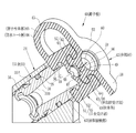
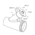
図2に示すように、処置具導入部24には、口金33がネジ留めされる。口金33は金属製で筒状に形成される。図3に示すように、口金33の外周面33Aには、下から順に雄ねじ部34、Oリング収納溝35、鉗子栓取付溝36、円環状突出部37が形成される。Oリング収納溝35にはOリング38が収納される。Oリング38は処置具導入部24と口金33の外周面33Aとの間を水密に保持する。内周面33Bは外側に向かうに従い次第に開拡するテーパー面状に形成されており、ガイド面となる。このガイド面により、処置具が処置具挿通チャンネル31に円滑に案内される。
As shown in FIG. 2, the
鉗子栓取付溝36、円環状突出部37が形成される口金33の外側端部は、処置具導入部24に口金33が取り付けられた状態で、外部に突出し露呈する(図2参照)。この鉗子栓取付溝36、円環状突出部37により口金嵌合部39が構成される。
The outer end portion of the base 33 in which the forceps
鉗子栓40は、滅菌済みで使用後は使い捨てにされるディスポーザルタイプとして提供され、図2に示すように使用時に口金33に嵌着される。そして、図4に示すような使用状態となる。 The forceps plug 40 is provided as a disposable type that is sterilized and disposable after use, and is fitted to the base 33 during use as shown in FIG. And it will be in a use condition as shown in FIG.
図5に示すように、鉗子栓40は、栓本体41、弁部材42、これらを連結する連結帯片43を備える。そして、展開した状態では、連結帯片43の一端部に栓本体41が、他端部に弁部材42がそれぞれ形成される。栓本体41は、略円筒状に構成される。栓本体41の下側部分の内周面には口金受け部45が、栓本体41の上側部分の内周面には弁部材受け部46が形成される。口金受け部45と弁部材受け部46との間は隔壁部47となっている。隔壁部47の中央には、処置具が挿通する絞り通路48が形成される。また、絞り通路48の上側縁部は円錐状に切り欠かれており、処置具先端を絞り通路48に案内するためのガイド面49になる。
As shown in FIG. 5, the forceps plug 40 includes a plug body 41, a valve member 42, and a connecting
口金受け部45は、円環状突出部51及び周溝52を有する。円環状突出部51は口金33の鉗子栓取付溝36に入り込み嵌合する。また、周溝52には口金33の円環状突出部37が入り込み嵌合する。これらの嵌合によって、栓本体41が口金33に着脱自在に固定される。
The base receiving part 45 has an annular projecting
弁部材42は、ベース部55、逆止弁部56、弁部材嵌合部57を備える。図3に示すように、ベース部55は連結帯片43に連続し円盤状に形成される。そして、一方の側縁に連結帯片43が連結され、他方の側縁に摘まみ片58が連結される。ベース部55には逆止弁部56の形成面とは反対側の面に、円穴状の凹みからなるガイド面59が形成される。逆止弁部56にはスリット60が形成される。スリット60の接触面は互いに密着しており、密着状態では水密状態を保つ。また、ガイド面59から処置具が挿入されると、処置具の挿入によってスリット60が弾性変形して開き、処置具の挿通が可能になる。また、スリット60の弾性力によりスリット面が処置具に密着するため、処置具と弁部材42とが水密に維持され、体内から逆流する血液や体液などが鉗子栓40から洩れだすことがない。
The valve member 42 includes a
弁部材嵌合部57は、逆止弁部56の外周面に形成される円環状突出部61と周溝62とを有する。弁部材受け部46は、弁部材嵌合部57を受けるものであり、弁部材嵌合部57の円環状突出部61が嵌合する周溝63と、弁部材嵌合部57の周溝62が嵌合する円環状突出部64とを有する。これら弁部材嵌合部57と弁部材受け部46との嵌合により、弁部材42が栓本体41に着脱自在に取り付けられる。
The valve
口金嵌合部39と口金受け部45とによる取り付け強度に比べて、弁部材嵌合部57と弁部材受け部46とによる取り付け強度は小さく設定される。したがって、摘まみ片58を摘んで弁部材42を引き起こして、弁部材受け部46から弁部材嵌合部57を取り外すときに、鉗子栓40が口金33から脱落することはない。
Compared with the attachment strength by the base fitting part 39 and the base receiving part 45, the attachment strength by the valve
本第1実施形態では、鉗子栓本体65は水膨張性エラストマにより一体成型される。そして、内視鏡に取り付けられた状態では水に接触して膨張することがないように、円環状突出部51の内周面51Aの一部(図5のクロスハッチ部分)51Bを除いて、鉗子栓本体65の全面に防水コート層66が被覆される。また、内周面51Aの一部51Bは防水コート層66が被覆されない。この防水コート層66が被覆されない一定幅の非防水部51Bが、液体接触部67となる。
In the first embodiment, the forceps plug main body 65 is integrally formed of a water-swellable elastomer. And, in a state where it is attached to the endoscope, so as not to expand in contact with water, except for a part of the inner
水膨張性エラストマは、水を吸収することにより体積が膨張するエラストマであり、ゴム系基本材料と吸水性材料とを複合化したものであり、市販のものが用いられる。 The water-swellable elastomer is an elastomer whose volume expands by absorbing water, is a composite of a rubber-based basic material and a water-absorbing material, and is commercially available.
液体接触部67の形成方法は、非防水部51Bにマスキングテープなどのマスキング部材を配置して、防水コート層66を例えば塗布により形成する。この防水コート層66が乾燥した状態で、マスキング部材を取り除くことにより、液体接触部67が形成される。また、マスキング部材を取り付ける代わりに、マスキング部材取付位置に接触する円周面を有する鉗子栓保持部材を設け、この鉗子栓保持部材を用いて鉗子栓40に防水コート層66を塗布してもよい。この場合には、鉗子栓保持部材が接触した部分は防水コート層66が塗布されないため、液体接触部67を構成することができる。
The liquid contact part 67 is formed by arranging a masking member such as a masking tape on the
図2に示すように、内視鏡の処置具導入部24に鉗子栓40を取り付けると、口金嵌合部39が口金受け部45に嵌合し、両者が密着する。したがって、口金33から鉗子栓40が脱落することはない。また、口金33に栓本体41が密着して嵌合するため、液体接触部67はこの密着部を介して、処置具挿通チャンネル31と隔離される。これにより、血液、体液、汚物、洗浄液などの液体と液体接触部67とは接触することがない。また、鉗子栓本体65は防水コート層66により覆われるため、内視鏡の使用状態において、液体吸引による膨張が発生することはない。
As shown in FIG. 2, when the forceps plug 40 is attached to the treatment
図1に示すように、使用に際しては、操作部12を操作して、被検体内に挿入部13を挿入し、所定の患部に挿入部先端を位置させて、観察や処置を行う。処置具11を使用する場合には、鉗子栓40のスリット60(図2参照)から処置具先端を挿入し、処置具挿通チャンネル31を介して、被検体内に処置具11を挿入する。所定の処置を行った後は、鉗子栓40から処置具11を取り出した後に、吸引ボタン23の操作によって、処置具挿通チャンネル31から被検体内の血液、体液、汚物、洗浄液などを吸入する。なお、基本的には弁部材42を弁部材受け部46に取り付けた状態で使用するが、カニュレーションチューブなどのコシの弱いものを鉗子栓40から挿通するときには、挿入抵抗を小さくするために、弁部材42を弁部材受け部46から外した状態で使用することもある。
As shown in FIG. 1, in operation, the
内視鏡の操作が全て完了した後に、内視鏡10からは鉗子栓40やその他の付属物が外された後に、図示しない洗浄機に入れられて、処置具挿通チャンネル31内や挿入部13の外面などが洗浄される。通常は、鉗子栓40はディスポーザルタイプとして提供されており、使い捨てにされる。しかし、一部の術者によっては、鉗子栓40も洗浄して再度使用することもあり、洗浄や消毒が完全でない状態で使い回しされるおそれもある。この場合には、患者や術者への感染などの危惧もあり好ましくない。
After all the operations of the endoscope are completed, the forceps plug 40 and other accessories are removed from the
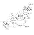
本第1実施形態では、鉗子栓40を内視鏡10から取り外して洗浄すると、液体接触部67が口金33との嵌合を外れ、図3に示すように、外部に剥き出しの状態になる。この状態で、水などで洗浄を行うと、液体接触部67に水が接触する。鉗子栓本体65は、水膨張性エラストマにより構成されるため、内部の吸水性ポリマが水を吸って、図6(A)に示す使用状態から、(B)に示すように、例えば体積が2〜6倍程度に膨れ上がる。また、洗浄を止めて水との接触を絶つと、吸水した水分が乾燥し、乾燥した分だけ膨張率は小さくなるものの、(C)に示すように、空気中の水分量とバランスした状態で膨れた状態を保つ。したがって、元の大きさである(A)の状態に復元することはなく、口金33に鉗子栓40を取り付けることができなくなり、再使用が阻止される。
In the first embodiment, when the forceps plug 40 is removed from the
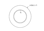
次に、図7〜図10を参照して、本発明の第2実施形態について説明する。第2実施形態では、第1実施形態のように、鉗子栓40を水膨張性エラストマからなる鉗子栓本体65と、一部に液体接触部67を有する防水コート層66とにより構成する代わりに、液体接触部67が形成される円環状突出部51のみを、図7及び図8に示すように、係止リング70として鉗子栓本体71とは別部材で構成した鉗子栓72を用いる。係止リング70は、水溶性エラストマにより、横断面が矩形のリング状に形成される。
Next, a second embodiment of the present invention will be described with reference to FIGS. In the second embodiment, as in the first embodiment, instead of configuring the forceps plug 40 with a forceps plug main body 65 made of a water-swellable elastomer and a waterproof coat layer 66 having a liquid contact portion 67 in part, As shown in FIGS. 7 and 8, only the
水溶性エラストマは、エラストマ基材に対して例えば水溶性ポリマを50%以上(重量割合)含ませたものが用いられるが、単に水に溶けて形状を維持することができなくなる程度の変形が得られるものであればよく、その材質などは特に限定されない。例えば、圧縮パルプやゼラチン及びその混合物などが用いられる。また、係止リング70が弾性変形して、円環状突出部37を乗り越えて口金嵌合部39に嵌合することができる程度の弾性力を備えていればよく、エラストマに限定されることなく、ポリマであってもよい。
As the water-soluble elastomer, for example, an elastomer base containing 50% or more (weight ratio) of a water-soluble polymer is used. However, the water-soluble elastomer can be deformed to such an extent that it cannot be simply dissolved in water to maintain its shape. The material is not particularly limited. For example, compressed pulp, gelatin and a mixture thereof are used. Further, it is sufficient that the locking ring 70 is elastically deformed and has an elastic force enough to be able to get over the annular projecting
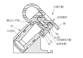
図9に示すように、係止リング70は、鉗子栓本体71が口金33に取り付けられた状態で、鉗子栓本体71と口金33との間に入る。このため、図7に示すように、鉗子栓本体71は、口金嵌合部39の円環状突出部37が嵌合する第1周溝75の他に、係止リング70の外周部分が入り込む第2周溝76が形成される。また、係止リング70は口金33の鉗子栓取付溝36に入り込む。なお、第1実施形態と同一構成部材には同一符号が付してあり、重複した説明を省略している。
As shown in FIG. 9, the locking ring 70 enters between the forceps plug
鉗子栓本体71は、従来の栓本体と同じようにゴムなどのエラストマにより構成する。第2実施形態では、係止リング70のみを水溶性エラストマにより構成するため、製造が容易になる。また、使用に際しては、鉗子栓72が口金33に嵌合し、口金嵌合部39の円環状突出部37と鉗子栓本体71の第1周溝75とが密着することによって、係止リング70に液体が進入することはなく、嵌合状態が保たれ、通常通りに使用することができる。
The forceps plug
内視鏡の使用後に、鉗子栓72を取り外して洗浄することにより、係止リング70は水溶性材料で構成されるため、水によって溶けて小さくなったり、または消滅する。したがって、係止リング70を再使用することができなくなる。このため、図10に示すように、鉗子栓本体71を口金33に嵌合しようとしても、係止リング70が無いため、鉗子栓本体71を口金33に係止させることができなくなり、再使用が防止される。
After the use of the endoscope, the forceps plug 72 is removed and washed, so that the locking ring 70 is made of a water-soluble material, so that it melts with water and becomes smaller or disappears. Therefore, the locking ring 70 cannot be reused. Therefore, as shown in FIG. 10, even if the forceps plug
なお、第2実施形態では、係止リング70を水溶性ポリマにより形成しているが、この他に、水膨張性ポリマ(水膨張性エラストマを含む)で係止リング70を構成してもよい。この場合にも、内視鏡から鉗子栓本体71を取り外し洗浄すると、例えば水を吸引して膨張し、係止リング70として再使用することができなくなる。
In the second embodiment, the locking ring 70 is formed of a water-soluble polymer. Alternatively, the locking ring 70 may be formed of a water-swellable polymer (including a water-swellable elastomer). . Also in this case, when the forceps plug
また、上記実施形態では、係止リング70として鉗子栓本体71とは別部材として構成したが、これに代えて、係止リング部分も例えば二次成形により鉗子栓本体71と一体的に形成してもよい。この場合には、水溶性エラストマや水膨張性エラストマを用いて、係止リング部分を二次成形する。
In the above embodiment, the locking ring 70 is configured as a separate member from the forceps plug
上記第1実施形態では、栓本体41のみならず、弁部材42、連結帯片43も水膨張性エラストマにより構成したが、栓本体41のみを水膨張エラストマから構成してもよい。また、第1実施形態では、防水コート層66を鉗子栓本体の表面に、塗布により形成したが、一次成型により、例えば栓本体の外郭のみを通常のポリマで構成し、次に、二次成型により外郭ポリマの中に、水膨張エラストマを成形してもよい。この場合には、外郭ポリマを水膨張エラストマの膨張に追随して膨張可能な厚みや材料で形成する。
In the first embodiment, not only the plug main body 41 but also the valve member 42 and the connecting
上記各実施形態では、液体接触部67を円環状突出部51の内周面に形成しているが、水との接触面積を高めるために、図11に示すように、液体接触部67に、所定ピッチで放射線方向や、その他の任意方向に水侵入穴80を設けてもよい。また、水侵入穴80の代わりに、図12に示すように、係止リング81の内周面を凹凸面82から構成して液体との接触面積を高めてもよい。凹凸面82は図示のような横断面が三角形状の筒方向に長い突条から構成する他に、半球状や円錐状の突起や穴を多数設けて凹凸面を形成してもよい。また、凹凸面82は、液体接触部67に形成してもよく、さらには、水侵入穴80と凹凸面82とを組み合わせて用いてもよい。
In each of the above embodiments, the liquid contact portion 67 is formed on the inner peripheral surface of the
上記各実施形態では、内視鏡10に用いられる栓体として鉗子栓40について説明したが、鉗子栓40以外にも、内視鏡10の栓体としてディスポーザルタイプとして使い捨てで用いられるもの、例えば吸引ボタンなどに対し、本発明を実施してもよい。この場合には、栓本体を水膨張性エラストマから構成し、表面に防水コート層を施す。使用時には内視鏡10に密着し水密に結合しており、使用後に洗浄する場合には内視鏡10から取り外される。そして、内視鏡10から取り外されると、水密に口金等の取付部分に密着していた部分が外部に露呈する。このように取り外した状態で外部に露呈する部分に、液体接触部を形成し、この液体接触部を介し洗浄時に洗浄液に触れさせて、栓本体を膨張させることにより、形状を変化させて、再使用することが阻止される。また、栓本体の液体接触部を水溶性エラストマから構成しても、同様に、水に接触して溶けて、現状の形状を維持することができなくなり、再使用を阻止することができる。
In each of the above-described embodiments, the forceps plug 40 is described as a plug used for the
上記実施形態では、処置具導入部に口金を介して鉗子栓を取り付けたが、処置具導入部に口金嵌合部が一体的に形成されている内視鏡では、口金は使用せずに処置具導入部に一体的に形成された口金嵌合部に鉗子栓を取り付けてもよい。 In the above embodiment, the forceps plug is attached to the treatment instrument introduction part via the base. However, in an endoscope in which the base fitting unit is integrally formed with the treatment instrument introduction part, the treatment is performed without using the base. A forceps plug may be attached to the fitting fitting portion formed integrally with the tool introduction portion.
Claims (8)
筒状の栓本体と、
前記栓本体に形成され、前記取付部に嵌合し、前記取付部からの前記栓本体の挿脱方向移動を阻止する取付受け部と、
前記取付部に前記取付受け部が嵌合している状態において、液体から隔離される位置で前記取付受け部に形成され、前記液体に接触して前記取付受け部を前記取付部に嵌合不能な状態にする液体接触部と
を有することを特徴とする内視鏡の栓体。 An endoscope plug body attached to an attachment portion of an endoscope,
A tubular plug body;
An attachment receiving portion that is formed on the plug body, fits into the attachment portion, and prevents movement of the plug body in the insertion / removal direction from the attachment portion;
In the state in which the mounting receiving portion is fitted to the mounting portion, the mounting receiving portion is formed at a position isolated from the liquid, and the mounting receiving portion cannot be fitted to the mounting portion in contact with the liquid. An endoscope plug body, characterized by comprising a liquid contact portion for bringing the state into a stable state.
前記栓体は、処置具が挿通される処置具挿通穴を有し、前記口金に嵌合する口金受け部が前記取付受け部であり、
前記口金に前記口金受け部が嵌合している状態において、前記処置具挿通チャンネルからの液体から隔離される位置で前記口金受け部に前記液体接触部が形成されていることを特徴とする請求項1記載の内視鏡の栓体。 The attachment portion is a substantially cylindrical base leading to a treatment instrument insertion channel in the endoscope,
The plug has a treatment instrument insertion hole through which a treatment instrument is inserted, and a base receiving part that fits into the base is the attachment receiving part.
The liquid contact portion is formed in the base receiving portion at a position isolated from the liquid from the treatment instrument insertion channel in a state where the base receiving portion is fitted to the base. Item 1. The endoscope plug according to Item 1.
前記口金受け部は、前記栓本体の内周面に形成され、前記口金側円環状突出部に嵌合する栓本体側周溝と、前記栓本体の内周面に形成され、前記口金側周溝に嵌合する栓本体側円環状突出部とを有し、
前記液体接触部は、前記栓本体側円環状突出部の内周面に形成されることを特徴とする請求項2記載の内視鏡の栓体。 The base has a base fitting portion at an outer end, and the base fitting portion has a base-side annular projecting portion projecting outward from the outer peripheral surface, and a base-side circumferential groove formed on the outer peripheral surface. Have
The base receiving portion is formed on the inner peripheral surface of the stopper main body, and is formed on the inner peripheral surface of the stopper main body, and on the inner peripheral surface of the stopper main body. A plug body-side annular projection that fits into the groove;
3. The endoscope plug according to claim 2, wherein the liquid contact portion is formed on an inner peripheral surface of the plug main body side annular projecting portion.
前記口金受け部は、前記栓本体の内周面に形成され、前記口金側円環状突出部に嵌合する栓本体側第1周溝と、前記栓本体側第1周溝よりも大きな内径を有する栓本体側第2周溝と、前記栓本体側第2周溝に外周部が嵌合し、前記口金側周溝に内周部が嵌合する係止リングとを有し、
前記液体接触部は、前記係止リングに形成されることを特徴とする請求項2記載の内視鏡の栓体。 The base has a base fitting portion at an outer end, and the base fitting portion has a base-side annular projecting portion projecting outward from the outer peripheral surface, and a base-side circumferential groove formed on the outer peripheral surface. Have
The base receiving portion is formed on the inner peripheral surface of the plug body, and has a plug body side first circumferential groove that fits into the base side annular projecting portion, and an inner diameter larger than the plug body side first circumferential groove. A stopper body-side second circumferential groove, and a stopper ring in which an outer peripheral portion is fitted into the stopper body-side second circumferential groove, and an inner peripheral portion is fitted into the cap-side circumferential groove,
3. The endoscope plug according to claim 2, wherein the liquid contact portion is formed on the locking ring.
前記液体接触部を除く栓本体の外面には防水コート層を有することを特徴とする請求項1から3いずれか1項記載の内視鏡の栓体。 The plug body is composed of a water expansion member that absorbs water and expands,
The endoscope plug body according to any one of claims 1 to 3, further comprising a waterproof coating layer on an outer surface of the plug body excluding the liquid contact portion.
Priority Applications (2)
| Application Number | Priority Date | Filing Date | Title |
|---|---|---|---|
| JP2011159934A JP5259783B2 (en) | 2011-07-21 | 2011-07-21 | Endoscope plug |
| CN 201220308840 CN202636888U (en) | 2011-07-21 | 2012-06-28 | Plug body and endoscope |
Applications Claiming Priority (1)
| Application Number | Priority Date | Filing Date | Title |
|---|---|---|---|
| JP2011159934A JP5259783B2 (en) | 2011-07-21 | 2011-07-21 | Endoscope plug |
Publications (2)
| Publication Number | Publication Date |
|---|---|
| JP2013022245A JP2013022245A (en) | 2013-02-04 |
| JP5259783B2 true JP5259783B2 (en) | 2013-08-07 |
Family
ID=47406083
Family Applications (1)
| Application Number | Title | Priority Date | Filing Date |
|---|---|---|---|
| JP2011159934A Expired - Fee Related JP5259783B2 (en) | 2011-07-21 | 2011-07-21 | Endoscope plug |
Country Status (2)
| Country | Link |
|---|---|
| JP (1) | JP5259783B2 (en) |
| CN (1) | CN202636888U (en) |
Families Citing this family (3)
| Publication number | Priority date | Publication date | Assignee | Title |
|---|---|---|---|---|
| CN107949332B (en) * | 2015-09-09 | 2020-12-01 | 学校法人东京女子医科大学 | Therapeutic substance delivery device and therapeutic substance delivery kit |
| WO2020148830A1 (en) * | 2019-01-16 | 2020-07-23 | オリンパス株式会社 | Insertion device |
| CN114557733B (en) * | 2022-02-28 | 2023-03-21 | 常州市久虹医疗器械有限公司 | Biopsy valve for endoscope |
Family Cites Families (3)
| Publication number | Priority date | Publication date | Assignee | Title |
|---|---|---|---|---|
| JPH02283345A (en) * | 1989-04-25 | 1990-11-20 | Olympus Optical Co Ltd | Stopper body for medical use |
| JP4594670B2 (en) * | 2004-08-04 | 2010-12-08 | オリンパス株式会社 | Endoscopic treatment tool stopper |
| JP2006055446A (en) * | 2004-08-20 | 2006-03-02 | Pentax Corp | Endoscopy forceps plug |
-
2011
- 2011-07-21 JP JP2011159934A patent/JP5259783B2/en not_active Expired - Fee Related
-
2012
- 2012-06-28 CN CN 201220308840 patent/CN202636888U/en not_active Expired - Lifetime
Also Published As
| Publication number | Publication date |
|---|---|
| CN202636888U (en) | 2013-01-02 |
| JP2013022245A (en) | 2013-02-04 |
Similar Documents
| Publication | Publication Date | Title |
|---|---|---|
| CN100558285C (en) | Endoscope insertion portion, endoscope, and endoscope system | |
| JP7026645B2 (en) | Clot drainage and visualization device and usage | |
| US11849917B2 (en) | Disposable miniature endoscopy system | |
| US20170231477A1 (en) | Instrument port with integrated imaging system | |
| US20070118013A1 (en) | Endoscope and method for repairing the same | |
| JP5285649B2 (en) | Endoscope hood | |
| JP2011200356A (en) | Endoscope insertion auxiliary tool | |
| JP2011200358A (en) | Endoscope insertion aid | |
| WO2008018256A1 (en) | Endoscope end device and container containing it | |
| WO2019075705A1 (en) | Protective sheath, hysteroscope equipped therewith, and nephroscope equipped with same | |
| JP2013138790A (en) | Endoscope washing sheath | |
| JP5259783B2 (en) | Endoscope plug | |
| JP7046336B2 (en) | Flexible ureteroscope introduction device and renal pelvis ureteroscope system | |
| JPH07148105A (en) | Endoscope with covering | |
| CN101652093A (en) | Drape for medical equipment, drape for endoscope, and medical device | |
| KR102220558B1 (en) | Disposable endoscopic structure for preventing cross infection | |
| JP4524393B2 (en) | Rapalloport | |
| JP2551545Y2 (en) | Ultrasonic endoscope tip protection cap | |
| JP2006055446A (en) | Endoscopy forceps plug | |
| US9931029B2 (en) | Washing system | |
| KR102582686B1 (en) | Endoscope cover assembly | |
| JP3462597B2 (en) | Ultrasound endoscope tip | |
| JP7098841B2 (en) | Endoscope tip cover, endoscope device | |
| JP3881537B2 (en) | Endoscope manufacturing method and endoscope | |
| JP4996265B2 (en) | Cleaning plug |
Legal Events
| Date | Code | Title | Description |
|---|---|---|---|
| A621 | Written request for application examination |
Free format text: JAPANESE INTERMEDIATE CODE: A621 Effective date: 20130118 |
|
| A977 | Report on retrieval |
Free format text: JAPANESE INTERMEDIATE CODE: A971007 Effective date: 20130405 |
|
| TRDD | Decision of grant or rejection written | ||
| A01 | Written decision to grant a patent or to grant a registration (utility model) |
Free format text: JAPANESE INTERMEDIATE CODE: A01 Effective date: 20130410 |
|
| A61 | First payment of annual fees (during grant procedure) |
Free format text: JAPANESE INTERMEDIATE CODE: A61 Effective date: 20130424 |
|
| FPAY | Renewal fee payment (event date is renewal date of database) |
Free format text: PAYMENT UNTIL: 20160502 Year of fee payment: 3 |
|
| R150 | Certificate of patent or registration of utility model |
Ref document number: 5259783 Country of ref document: JP Free format text: JAPANESE INTERMEDIATE CODE: R150 Free format text: JAPANESE INTERMEDIATE CODE: R150 |
|
| R250 | Receipt of annual fees |
Free format text: JAPANESE INTERMEDIATE CODE: R250 |
|
| R250 | Receipt of annual fees |
Free format text: JAPANESE INTERMEDIATE CODE: R250 |
|
| R250 | Receipt of annual fees |
Free format text: JAPANESE INTERMEDIATE CODE: R250 |
|
| R250 | Receipt of annual fees |
Free format text: JAPANESE INTERMEDIATE CODE: R250 |
|
| R250 | Receipt of annual fees |
Free format text: JAPANESE INTERMEDIATE CODE: R250 |
|
| LAPS | Cancellation because of no payment of annual fees |

