JP5259478B2 - Channel open / close valve - Google Patents
Channel open / close valve Download PDFInfo
- Publication number
- JP5259478B2 JP5259478B2 JP2009088106A JP2009088106A JP5259478B2 JP 5259478 B2 JP5259478 B2 JP 5259478B2 JP 2009088106 A JP2009088106 A JP 2009088106A JP 2009088106 A JP2009088106 A JP 2009088106A JP 5259478 B2 JP5259478 B2 JP 5259478B2
- Authority
- JP
- Japan
- Prior art keywords
- shaft
- valve
- flow path
- ball valve
- concave portion
- Prior art date
- Legal status (The legal status is an assumption and is not a legal conclusion. Google has not performed a legal analysis and makes no representation as to the accuracy of the status listed.)
- Expired - Fee Related
Links
Images


Classifications
-
- Y—GENERAL TAGGING OF NEW TECHNOLOGICAL DEVELOPMENTS; GENERAL TAGGING OF CROSS-SECTIONAL TECHNOLOGIES SPANNING OVER SEVERAL SECTIONS OF THE IPC; TECHNICAL SUBJECTS COVERED BY FORMER USPC CROSS-REFERENCE ART COLLECTIONS [XRACs] AND DIGESTS
- Y02—TECHNOLOGIES OR APPLICATIONS FOR MITIGATION OR ADAPTATION AGAINST CLIMATE CHANGE
- Y02T—CLIMATE CHANGE MITIGATION TECHNOLOGIES RELATED TO TRANSPORTATION
- Y02T10/00—Road transport of goods or passengers
- Y02T10/10—Internal combustion engine [ICE] based vehicles
- Y02T10/12—Improving ICE efficiencies
Landscapes
- Exhaust-Gas Circulating Devices (AREA)
- Taps Or Cocks (AREA)
- Mechanically-Actuated Valves (AREA)
- Indication Of The Valve Opening Or Closing Status (AREA)
- Details Of Valves (AREA)
Description
本発明は、流路開閉弁に関し、一層詳細には、内燃機関から排出される排気ガスが流通する流路等に介装されて該流路の開閉を行う流路開閉弁に関する。 The present invention relates to a flow path opening / closing valve, and more particularly to a flow path opening / closing valve that is interposed in a flow path or the like through which exhaust gas discharged from an internal combustion engine flows to open and close the flow path.
この種の流路開閉弁には、排気ガスを再循環させるための流路開閉弁として用いられるものがある。実開平6−16774号公報(特許文献1)には、この種の排気流路開閉弁として球状の弁体を有する「ボールバルブ」構造が開示されている。この球状弁体を回動させるためのシャフト軸は前記球状弁体の上部に設けられた溝に嵌合され、シャフト軸が回動することによって、流路の開閉を行う。この特許文献1に開示されている流路開閉弁の構成では、前記溝の側壁は互いに平行な側面部で構成され、シャフト軸の先端は平面部を有し、該シャフト軸の前記各平面部は前記嵌合溝を形成する二つの平行な側面に対面するように挿入される。 Some of these types of flow path opening / closing valves are used as flow path opening / closing valves for recirculating exhaust gas. Japanese Utility Model Laid-Open No. 6-16774 (Patent Document 1) discloses a “ball valve” structure having a spherical valve body as this type of exhaust passage opening / closing valve. A shaft shaft for rotating the spherical valve body is fitted into a groove provided in the upper portion of the spherical valve body, and the flow path is opened and closed by rotating the shaft shaft. In the configuration of the flow path opening / closing valve disclosed in Patent Document 1, the side wall of the groove is formed of side surfaces parallel to each other, the tip of the shaft shaft has a flat surface portion, and each of the flat surface portions of the shaft shaft. Is inserted so as to face two parallel side surfaces forming the fitting groove.
特公平6−5111号公報(特許文献2)は「ボール弁」に関するものであって、流路を開成閉成するために弁本体の上部に円弧面を持つように膨出形成されたシャフト軸先端構造を採用する。 Japanese Examined Patent Publication No. 6-5111 (Patent Document 2) relates to a “ball valve”, and a shaft shaft bulged to have an arc surface at the top of a valve body in order to open and close a flow path. Adopting a tip structure.
特開2008−208984号公報(特許文献3)は「ガスコック」に関するものであって、この「ガスコック」は、開閉弁の上部に設けられた嵌合溝にシャフト軸が嵌合してシャフト軸の回動動作に伴って前記開閉弁が流路を開閉する。前記シャフト軸の先端部は、断面外側に凸形状の円弧面を有する。従って、前記凸形状の円弧面は、平面で構成された嵌合溝側面部と線接触して開閉動作するための回動力を付与する。 Japanese Patent Application Laid-Open No. 2008-208984 (Patent Document 3) relates to a “gas cock”, and this “gas cock” is configured such that a shaft shaft is fitted into a fitting groove provided in an upper portion of an on-off valve and the shaft shaft is fitted. The on-off valve opens and closes the flow path in accordance with the turning operation. The tip of the shaft has a convex arcuate surface on the outer side of the cross section. Therefore, the convex circular arc surface gives a rotational force for opening and closing operation in line contact with the side surface portion of the fitting groove constituted by a plane.
ところで、特許文献1の従来技術によれば、シャフト軸の先端が平面部を有し、嵌合溝側面との間に間隙が形成されるため、アクチュエータの付勢作用下にシャフト軸側面が嵌合溝を形成する弁体側の側面と接触するには、所定の時間遅れがあり、シャフト軸とボールバルブの回転動作にずれが生じ、流路を流れる流体の量を適切に把握できないという不都合がある。特許文献2の従来技術によれば、前記のようにシャフト軸と開閉弁に設けられた溝側面との嵌合は線接触で行われる。その結果、シャフト軸先端側面と嵌合溝を形成する接触面積が減少し、嵌合溝にシャフト軸先端を嵌合することは容易であるが、特許文献1の従来技術と同様に、シャフト軸先端側面と嵌合溝の側面との間に製造誤差に基因する間隙が生じ、シャフト軸の回動と開閉弁の回動との間に時間的なずれが生じ、応答性に難点がある。さらに、前記特許文献3の従来技術によれば、シャフト軸先端には断面外側に膨出する円弧面が形成される構成を採用しているが、特許文献1や特許文献2に記載の従来技術と同様に、シャフト軸と開閉弁との間に製造誤差が生じ、この結果、シャフト軸の回動と開閉弁の回動動作との間に時間差が生じて、応答性が悪いという不都合がある。 By the way, according to the prior art of Patent Document 1, since the tip of the shaft shaft has a flat portion and a gap is formed between the side surface of the fitting groove, the shaft shaft side surface is fitted under the biasing action of the actuator. There is a predetermined time delay in contact with the side surface on the valve element side that forms the joint groove, and there is a disadvantage that the rotational operation of the shaft shaft and the ball valve is deviated, so that the amount of fluid flowing through the flow path cannot be properly grasped. is there. According to the prior art of Patent Document 2, as described above, the fitting between the shaft shaft and the side surface of the groove provided in the on-off valve is performed by line contact. As a result, the contact area for forming the fitting groove with the side surface of the shaft shaft tip is reduced, and it is easy to fit the tip of the shaft shaft into the fitting groove. A gap due to a manufacturing error is generated between the front end side surface and the side surface of the fitting groove, and a time lag occurs between the rotation of the shaft shaft and the rotation of the on-off valve, and there is a difficulty in responsiveness. Further, according to the prior art disclosed in Patent Document 3, a configuration is adopted in which an arc surface bulging outward in the cross section is formed at the tip of the shaft shaft, but the prior art described in Patent Document 1 and Patent Document 2 is employed. Similarly, a manufacturing error occurs between the shaft shaft and the opening / closing valve, and as a result, a time difference occurs between the rotation of the shaft shaft and the rotation operation of the opening / closing valve, resulting in inconvenience that the responsiveness is poor. .
本発明は、前記の従来技術を克服するためになされたものであって、アクチュエータによって回動されるシャフト軸とボールバルブとの回動動作のずれを低減することにより、シャフト軸の回動度に応じた流体の量を適切に把握でき、しかも、厳密な製造精度も要求されることなく、容易に組立てることが可能な、この結果、全体として製造コストを低廉化することができる流路開閉弁を提供することを目的とする。 The present invention has been made in order to overcome the above-described prior art, and reduces the rotational degree of the shaft shaft rotated by the actuator and the ball valve, thereby reducing the degree of rotation of the shaft shaft. It is possible to properly grasp the amount of fluid according to the flow rate, and it is easy to assemble without requiring strict manufacturing accuracy. As a result, the flow path opening and closing can reduce the manufacturing cost as a whole The purpose is to provide a valve.
前記の目的を達成するために、本願の発明は、ボールバルブと、前記ボールバルブを回転自在に収容する室が設けられ流体流入口と流体流出口とを設けたバルブ本体と、前記ボールバルブを前記室内で回動させて、前記流体流入口と流体流出口とを連通遮断するシャフト軸と、前記シャフト軸を回動するアクチュエータとを備え、前記ボールバルブに一組の対向する側面を有する凹部を形成し、前記シャフト軸の側方に前記ボールバルブの凹部内に配置され、前記凹部を形成する一組の側面の離間距離より狭い幅を有する一組の平面部と、前記平面部において、前記シャフト軸の先端部側に、前記一組の平面部のそれぞれより膨出し、前記離間距離と等しい幅を有する一組の曲面部とを、前記シャフト軸と一体形成し、前記曲面部を前記凹部を形成する側面間に嵌入して、前記アクチュエータの回転力を前記シャフト軸を介して前記ボールバルブに伝達し、前記ボールバルブの回動を行うことにより前記流体流入口と流体流出口の連通を開閉することを特徴とする。 To achieve the above object, inventions of the present application, a ball valve, and the valve body chamber for rotatably accommodating said ball valve is provided with fluid inlet and fluid outlet is provided, said ball valve And a shaft shaft that allows the fluid inlet and the fluid outlet to communicate with each other and an actuator that rotates the shaft shaft, and the ball valve has a pair of opposing side surfaces. A pair of flat portions formed in the concave portion of the ball valve on the side of the shaft axis and having a width narrower than a separation distance of a pair of side surfaces forming the concave portions; A pair of curved surface portions that bulge from each of the pair of flat surface portions and have a width equal to the separation distance are formed integrally with the shaft shaft on the tip end side of the shaft shaft, and the curved surface portion is The recess Fit between the side surfaces to be formed, transmit the rotational force of the actuator to the ball valve via the shaft, and rotate the ball valve to open and close the communication between the fluid inlet and the fluid outlet It is characterized by doing.
本願の請求項1の発明によれば、前記シャフト軸の先端部側に前記ボールバルブの凹部内に配置される平面部を設けたので、流路開閉弁を組み立てる際に前記凹部を形成するいずれか一方の側面に傾斜させた状態でシャフト軸先端部をボールバルブの凹部に嵌合させることができる。従って、組立時の自由度が増して組立容易性が確保され、製造コストも低廉化する。しかも、前記シャフト軸先端部側の一組の曲面部の幅員がボールバルブの凹部を形成する一組の側面の幅員と実質的に同一であるため、シャフト軸とボールバルブとの回動動作のずれを低減することにより、シャフト軸の回動度に応じた適切な流体流量を把握することができるという効果が得られる。 According to the invention of claim 1 of the present application, since the flat portion disposed in the concave portion of the ball valve is provided on the tip end side of the shaft shaft, any one of the concave portion is formed when the flow path opening / closing valve is assembled. The shaft shaft tip can be fitted into the concave portion of the ball valve while being inclined to one of the side surfaces. Accordingly, the degree of freedom during assembly is increased, the ease of assembly is ensured, and the manufacturing cost is reduced. In addition, since the width of the set of curved surface portions on the shaft shaft front end side is substantially the same as the width of the set of side surfaces forming the concave portion of the ball valve, the rotation of the shaft shaft and the ball valve can be performed. By reducing the deviation, it is possible to obtain an effect that an appropriate fluid flow rate corresponding to the degree of rotation of the shaft axis can be grasped.
本願の請求項2で特定される発明は、前記ボールバルブの凹部を形成する互いに対向する側面から連なる底部が湾曲する底面からなり、前記シャフト軸の底面は、湾曲若しくは鈍角状に屈曲して膨出する凸部として形成されることを特徴とする。 The invention specified in claim 2 of the present application comprises a bottom surface that curves from the opposite side surfaces forming the concave portion of the ball valve, and the bottom surface of the shaft shaft is bent or obtusely bent to expand. It is characterized by being formed as a protruding convex part.
本願の請求項2の発明によれば、シャフト軸の湾曲若しくは鈍角上に屈曲する凸部がボールバルブの凹部を形成する湾曲底面にスペースの無駄がない状態で嵌合する。従って、遊びがないために小型化に適し、省スペース化が図られるとともに長期間にわたる使用にも優れた耐久性が得られる。 According to the invention of claim 2 of the present application, the convex portion bent to the curved or obtuse angle of the shaft shaft is fitted to the curved bottom surface forming the concave portion of the ball valve with no waste of space. Therefore, since there is no play, it is suitable for downsizing, saving space, and excellent durability for long-term use.
本願の請求項3で特定される発明は、請求項1又は2に記載の流路開閉弁において、前記ボールバルブの凹部を形成する互いに対向する側面に対面する前記シャフト軸の一組の平面部の幅員は、該シャフト軸が前記凹部内で傾いたときに前記シャフト軸の曲面部が前記凹部内で揺動可能な厚みを有することを特徴とする。 The invention specified in claim 3 of the present application is the flow path on-off valve according to claim 1 or 2, wherein a set of flat portions of the shaft shaft facing the opposite side surfaces forming the concave portion of the ball valve. The width of the shaft is characterized in that the curved surface portion of the shaft shaft has a thickness capable of swinging in the recess when the shaft shaft is tilted in the recess.
本願の請求項3の発明によれば、ボールバルブにシャフト軸を係合する組立時に、シャフト軸が傾いたとしても、ボールバルブの凹部を形成する側面に当接しない厚さに平面部の幅員を選択している。従って、組立時の自由度が増し、生産効率も向上するという優れた効果が得られる。 According to the invention of claim 3 of the present application, even when the shaft shaft is tilted at the time of assembling to engage the ball valve, the width of the flat portion is set so as not to contact the side surface forming the concave portion of the ball valve. Is selected. Therefore, the excellent effect of increasing the degree of freedom during assembly and improving the production efficiency can be obtained.
本願の請求項4で特定される発明は、請求項1に記載の流路開閉弁において、前記シャフト軸の先端に設けられる一組の曲面部が一方の側面側に膨出する第1の膨出部と、前記凹部の他方の側面に対面する第2の膨出部とからなり、前記第1の膨出部と第2の膨出部のそれぞれの頂面の位置は鉛直方向において互いに偏位していることを特徴とする。 The invention specified in claim 4 of the present application is the flow path on-off valve according to claim 1, wherein a pair of curved surface portions provided at the tip of the shaft shaft bulge to one side surface side. A protruding portion and a second bulging portion facing the other side surface of the concave portion, and the positions of the top surfaces of the first bulging portion and the second bulging portion are mutually offset in the vertical direction. It is characterized by being ranked.
本願の請求項4の発明によれば、前記シャフト軸の第1の膨出部と第2の膨出部とが互いに鉛直方向に変位しているので、凹部の幅方向に多少の製造誤差があったとしても、シャフト軸を傾けることによって容易に且つ円滑にボールバルブの凹部に組み込むことができる効果が得られる。 According to the invention of claim 4 of the present application, since the first bulging portion and the second bulging portion of the shaft shaft are displaced in the vertical direction, there is a slight manufacturing error in the width direction of the concave portion. Even if it exists, the effect which can be integrated in the recessed part of a ball valve easily and smoothly by inclining a shaft axis is acquired.
本願の請求項5で特定される発明は、請求項1又は2に記載の流路開閉弁において、前記凹部を形成する一組の対向する側面の頂部が湾曲形状であることを特徴とする。 The invention specified in claim 5 of the present application is characterized in that, in the flow path on-off valve according to claim 1 or 2, top portions of a pair of opposing side surfaces forming the recess are curved.
本願の請求項5の発明によれば、凹部を形成する側面の頂部が湾曲形状であるのでシャフト軸の先端を容易に挿入でき、組立の容易性、製造コストの低廉化が図られる。 According to the invention of claim 5 of the present application, since the top of the side surface forming the concave portion is curved, the tip of the shaft shaft can be easily inserted, and the ease of assembly and the reduction of the manufacturing cost can be achieved.
本願の請求項6で特定される発明は、請求項1又は2に記載の流路開閉弁において、前記凹部を形成する一組の対向する側面は、前記凹部の底面から上方に進むにつれて互いに拡開していることを特徴とする。 The invention specified in claim 6 of the present application is the flow path on-off valve according to claim 1 or 2, wherein the pair of opposing side surfaces forming the recesses expand from each other as they proceed upward from the bottom surface of the recess. It is characterized by being open.
本願の請求項6の発明によれば、凹部の底面から上方に指向するに従って一組の側面が拡開している。従って、シャフト軸の先端を凹部に挿入したときに、該先端の幅員と凹部の幅員とが一致する箇所が必ず見出せる。このことは凹部やシャフト軸先端の製造精度をさほど厳しくしなくともよい。製造コストの低廉化の効果も得られる。 According to invention of Claim 6 of this application, a set of side surface is expanded as it points upwards from the bottom face of a recessed part. Therefore, when the tip end of the shaft shaft is inserted into the recess, a portion where the width of the tip matches the width of the recess can be always found. This does not require the manufacturing accuracy of the recess and the shaft shaft tip to be so severe. The effect of lowering the manufacturing cost can also be obtained.
本願の請求項7で特定される発明は、請求項1乃至6のいずれかに記載の流路開閉弁において、前記流路開閉弁がEGRバルブであることを特徴とする。 The invention specified in claim 7 of the present application is characterized in that in the flow path opening / closing valve according to any one of claims 1 to 6, the flow path opening / closing valve is an EGR valve.
本願の請求項7の発明によれば、シャフト軸の回動度に応じた適切な流体の流量を正確に把握できるので内燃機関から排出された排気ガスの量を制御して再び燃料室側へと送給するためのフィードバックを適確に行うことができる。 According to the invention of claim 7 of the present application, since it is possible to accurately grasp the flow rate of an appropriate fluid according to the degree of rotation of the shaft, the amount of exhaust gas discharged from the internal combustion engine is controlled to return to the fuel chamber side again. It is possible to accurately provide feedback for sending.
本発明によれば、流路開閉弁を構成するボールバルブに互いに平行な側面を備えた凹部を形成し、この凹部に平面部を備えたシャフト軸先端部を嵌合するように構成したので、該シャフト軸先端部を傾斜させた状態で凹部に挿入することによりシャフト軸をボールバルブに組み付けることができる。これによって、ボールバルブとシャフト軸の組立容易性が確保でき、製造コストを低廉化することが可能となるとともにシャフト軸の回動度に応じた適切な流体の流量を把握でき、それによってフィードバック制御を行えば、さらに正確な流体の流量調整を達成する効果が得られる。 According to the present invention, the ball valve constituting the flow path opening / closing valve is formed with a recess provided with side surfaces parallel to each other, and the shaft shaft tip provided with a flat portion is fitted into the recess. The shaft shaft can be assembled to the ball valve by inserting the shaft shaft tip portion into the concave portion in an inclined state. This makes it easy to assemble the ball valve and the shaft shaft, making it possible to reduce the manufacturing cost and grasping the appropriate fluid flow rate according to the degree of rotation of the shaft shaft, thereby providing feedback control. If this is performed, the effect of achieving more accurate fluid flow rate adjustment can be obtained.
本発明に係る流路開閉弁に関し、好適な実施の形態を挙げ、添付の図面を参照しながら以下詳細に説明する。 The flow path opening / closing valve according to the present invention will be described in detail below with reference to the accompanying drawings by giving preferred embodiments.
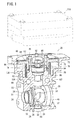
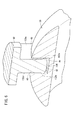
図1において、参照符号20は流路開閉弁の一つの実施の形態としての排気流路バルブ(以下、EGRバルブと称する)を示す。EGRバルブ20は、バルブ本体22を有し、このバルブ本体22の下側には、比較的小径な排気ガス流入口24と、その反対側に前記排気ガス流入口24に連通する比較的大径な排気ガス流出口26が設けられている。実際、前記排気ガス流入口24と排気ガス流出口26の間に室28が形成され、この室28の内部に変形した球状のボールバルブ30が回動自在に配設される。排気ガス流入口24側には、バルブ押さえ32が配設される。
In FIG. 1,
バルブ押さえ32は、図1、図2から容易に了解されるように、小径部34と、この小径部34と一体的且つ同軸な大径部36とからなり、前記小径部34は排気ガス流入口24に臨み、大径部36は前記ボールバルブ30に臨むように配設されている。大径部36には、ウェーブワッシャ38が設けられ、従って、このウェーブワッシャ38の弾発力によってバルブ押さえ32は常時排気ガス流出口26側へと弾発付勢されている。
As can be easily understood from FIGS. 1 and 2, the
この場合、前記ウェーブワッシャ38に対して、図2に示すように、小径部34側にプレーンワッシャ39を設けてもよい。このプレーンワッシャ39の介装によって大径部36をさらにボールバルブ30側に押し付けることにより、ウェーブワッシャ38とバルブ本体22との間隔の調整をより一層容易に行うことができる。さらに、ウェーブワッシャ38が直接バルブ本体22に接触しなくなることから、バルブ本体22の損傷を回避することができる。
In this case, a
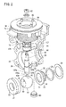
排気ガス流出口26側には、バルブシート37が配設される。このバルブシート37は円環状であって、バルブ本体22に設けられた円形状の溝41にしっかりと固定される。ボールバルブ30は、図2から容易に了解されるように、中心軸に直交するように一方の曲面と他方の曲面が取り除かれて、該中心軸に沿って一方の面から他方の面へと貫通孔40が形成された球体である。そして、この貫通孔40に直交する頂部には、平面長方形状の凹部42が形成される。図4及び図6から容易に了解されるように、前記凹部42は、屈曲又は湾曲する底面44とその両側の平行な第1の側面46と第2の側面48とを有する。好ましくは、前記ボールバルブ30は、前記貫通孔40に直交するように孔部50を形成し、また、変形例として、場合によって前記貫通孔40及び孔部50に直交する孔部52を設けるとよい(図4参照)。
A
前記ボールバルブ30は、後述するシャフト軸90によって回動されると、その貫通孔40がバルブ押さえ32に形成された通路51に連通するとともに、バルブシート37に形成された通路56と連通する。前記孔部50は排気ガス流入口24から送出される所定圧力の排気ガスを他の部位に迂回することのないように受け入れるためのものであり、孔部52はボールバルブ30の貫通孔40の内部に蓄積する炭素の微粒子を受容するためのものである。
When the
この場合、前記孔部52に対応して、バルブ本体22の前記孔部52の直下には、盲栓60を嵌合する孔部61を設けておく。ボールバルブ30の貫通孔40内に堆積する前記炭素の微粒子等を必要に応じて除去するためのものである。
In this case, a
次に、以上のように構成されるボールバルブ30を回動させるためのアクチュエータ側の構造について説明する。
Next, the structure on the actuator side for rotating the
バルブ本体22の上方には、小径な第1環状溝70と、この第1環状溝70に連通する大径な第2環状溝72が互いに連通して同軸的に形成され、前記第2環状溝72は外方に開放された状態にある。第1環状溝70から第2環状溝72にかけて、コイルスプリング74が設けられ、このコイルスプリング74の上端部に回転力伝達プレート76が配設される。回転力伝達プレート76は、その中心部分に下方へと開口する室78と、この室78と同軸で且つ狭径な上方へと開口する室80が設けられている。前記室80を構成する肉厚な環状の壁部82に連結ピン84が等間隔で複数本植設される。各々の連結ピン84の上部に金属製のチューブ85が被嵌される。前記壁部82を囲繞してロータ押さえ86が嵌合し、このロータ押さえ86の上面に金属板からなるロータ88が設けられている。前記ロータ88は、後述するアクチュエータ110からの回動動作によって回転力伝達プレート76がどの程度回動したかを検出するためのセンサの一部を構成する。
A small-diameter first
一方、室80の中心部には、シャフト軸90が前記ボールバルブ30側へと延在するようにナット92によって締め付けられている。実際、シャフト軸90はバルブ本体22に設けられた転がり軸受け94によって、その回動動作が円滑に行えるように構成され、さらに、前記転がり軸受け94と同軸的に且つその下方に排気ガスが外部に漏出しないようにシール96が設けられている。さらに、シール96の下方には、軸受け98が前記シール96から所定間隔離間して設けられている。
On the other hand, at the center of the
そこで、シャフト軸90の先端は、図2乃至図6から容易に了解されるように、二つの平行な側面100aと100bを有し、且つこの側面100a、100bが終端する下方は互いに外方へと膨出する曲面102a、102bとして形成されている。前記曲面102a、102bの下端部は、該曲面102a、102bの膨出方向に直交するように延在する円弧状の膨出部104に繋がっている。前記膨出部104、曲面102a、102b、側面100a、100bはシャフト軸90が組み付けられたとき、ボールバルブ30の凹部42に嵌合する。この場合、前記円弧状の膨出部104に代えて、図6に示すように屈曲する平面膨出部としてもよい。
Therefore, as easily understood from FIGS. 2 to 6, the tip of the
なお、図中、参照符号106、107は、前記EGRバルブ20を強制的に冷却するための図示しない冷却水供給用パイプに連通する孔部を示し、参照符号108はシール96と転がり軸受け94との間に設けられた金属製の押さえ板を示す。さらに、参照符号110は、前記シャフト軸90を開動するためのアクチュエータを示す。前記アクチュエータ110は、バルブ本体22の上部にロータ88を包被するように固着される。
In the figure,
本実施の形態に係るEGRバルブ20は、基本的には以上のように構成されるものであり、次にその作用並びに効果について説明する。
The
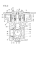
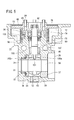
実際、アクチュエータ110は、ロータリーアクチュエータからなり、このアクチュエータ110が付勢されると、その回転力は、チューブ85が被嵌された連結ピン84に伝達される。前記のように連結ピン84には、チューブ85が被嵌されているために、アクチュエータ110が長期間にわたってその回動動作を繰り返しても連結ピン84がその摩擦によって損耗することはない。このように連結ピン84に回転力が伝達されると、前記連結ピン84を植設している回転力伝達プレート76が回動し、その回動量はロータ88によって検出されるとともに、ナット92によってその一端部が緊締されたシャフト軸90にその回転力が伝達される。シャフト軸90の先端部は前記のように平行な側面100a、100bと、曲面102a、102b及び膨出部104がしっかりとボールバルブ30の凹部42に密着嵌合しているため、時間的遅れを生じることなく前記ボールバルブ30がその回転力に応じて即時に回転するに至る。すなわち、バルブ押さえ32の通路51と、バルブシート37の通路56に密着して両通路51、56の連通を遮断している状態(図3参照)から、ボールバルブ30を図5の状態に回転すれば、排気ガス流入口24側の通路51がボールバルブ30の貫通孔40と連通し、さらにこの貫通孔40はバルブシート37側の通路56と連通して排気ガス流出口26に至る。従って、図示しないエンジンからの排気ガスが前記排気ガス流入口24に到達すると、通路51、貫通孔40、そして通路56を経て排気ガス流出口26から導出される。
Actually, the
一方、EGRバルブ20を閉成しようとするとき、前記と同様にアクチュエータ110からの回転力が連結ピン84に伝達され、ロータ88によってその位置が確認されるとともに、回転力伝達プレート76が回動し、シャフト軸90を経て、ボールバルブ30を図3に示す位置に回動せしめる。これによって、バルブシート37の通路56は完全に閉成されることから、図示しないエンジンからの排気ガスが流通することはない。なお、バルブシート37の閉成直後にエンジンからの排気ガスが、排気ガス流入口24に到達する場合がある。この排気ガスは、ボールバルブ30に到達し、孔部50から貫通孔40に至るが、この貫通孔40内に留まる。場合によって、ボールバルブ30の貫通孔40内に蓄積された排気ガス中に含まれる炭素等の微粒子は、孔部52に堆積することがある。従って、必要に応じて盲栓60を取り外して、ボールバルブ30の内部に蓄積された炭素の微粒子を外部に取り出すことができる。
On the other hand, when the
本実施の形態によれば、ボールバルブ30の頂部に互いに対向する側面46、48と、前記側面46、48に連続する凹部42を有する溝を形成し、アクチュエータ110の回転作用下に回動するシャフト軸90の先端に、前記ボールバルブ30の側面46、48の間隔と同一の幅員を有する曲面102a、102bを形成している。前記曲面102a、102bを前記凹部42に嵌合すれば、容易にシャフト軸90をボールバルブ30と一体化できる。そこで、シャフト軸90を回動させることによって、時間的遅れがなく、ボールバルブ30を回動することができる。従って、シャフト軸90の回転に対し、時間遅れがなく、ボールバルブ30を回転させることができるため、応答性に優れた流体開閉弁を得ることができる。ボールバルブ30の前記凹部42は、ボールバルブ30自体を切削加工して、或いは鋳造品として形成してもよく、シャフト軸90の側面100a、100b及び曲面102a、102bもまた機械加工により、或いは成形品として得ることができる。従って、従来の流体開閉弁に比し、安価に、しかも大量にこの種の流路開閉弁を得ることができる。
According to the present embodiment, the groove having the side surfaces 46, 48 facing each other and the
図7に本発明の別の実施形態を示す。この実施形態はシャフト軸90の先端に関するものである。すなわち、シャフト軸90の先端に側面100a、100bに連なって半球状の互いに反対側に膨出する曲面部200a、200bを設け、前記曲面部200a、200bはシャフト軸90の鉛直方向にあって偏位した形状である。このため、破線で示すように、シャフト軸90を傾斜させてボールバルブ30の凹部42に挿入することができる。組立の容易性が確保できる。
FIG. 7 shows another embodiment of the present invention. This embodiment relates to the tip of the
図8に本発明のまた別の実施形態を示す。この実施形態は、シャフト軸90の先端を凹部42の第1の側面46、第2の側面48に対向するようにこれらの側面46、48の延在方向に沿って全体として断面略卵状に膨出させ、曲面部300a、300bとしたものである。前記曲面部300aと300bの幅W1は前記凹部42の幅W2と等しい。この場合、本実施の形態では、凹部42の第1の側面46と第2の側面48の頂部に同一の曲率で湾曲部302aと302bを設けている。このように湾曲部302a、302bを設ける構造とすることにより、シャフト軸90の凹部42への挿入が一層容易となり、しかも凹部42を構成する第1の側面46と第2の側面48の幅W2に製造上のバラつきがあったとしても、曲面部300a、300bは卵状であるが故に必ず幅W1と一致する部位が存在する。このため、この種の流路開閉弁の製造が容易となる。
FIG. 8 shows another embodiment of the present invention. In this embodiment, the tip end of the
図9は本発明のさらにまた別の実施形態を示す。この実施形態では、凹部42を構成する第1の側面46と第2の側面48とを互いに離間するように拡開している。従って、シャフト軸90の曲面部300a、300bは図8の実施の形態と同じであるが、凹部42の幅W2はその溝の深さによって変化している。これによっても、図8の実施形態と同様な効果が得られる。
FIG. 9 shows yet another embodiment of the present invention. In this embodiment, the
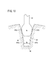
図10は本発明のまた更なる別の実施形態を示す。この実施形態では、凹部42を構成する第1の側面46と第2の側面48とを互いに離間するように拡開する曲面400a、400bで構成している。当然に、前記第1の側面46と第2の側面48の幅W2は可変である。これによっても、図8、図9の実施形態と同様の効果が得られる。
FIG. 10 shows yet another embodiment of the present invention. In this embodiment, the
以上、本発明について、好適な実施の形態を挙げて説明したが、本発明は前記実施の形態に限定されるものではなく、本発明の要旨を逸脱しない範囲において、種々の改変が可能なことは言うまでもない。特に、EGRバルブは排気ガス専用の流路開閉弁であるが、本実施の形態に係る流路開閉弁は、前記EGRバルブに限定されるものではなく、種々の流体の流路を開閉する弁として多くの用途に活用できることは言うまでもない。 The present invention has been described with reference to the preferred embodiments. However, the present invention is not limited to the above-described embodiments, and various modifications can be made without departing from the scope of the present invention. Needless to say. In particular, the EGR valve is a flow path opening / closing valve dedicated to exhaust gas, but the flow path opening / closing valve according to the present embodiment is not limited to the EGR valve, and is a valve for opening and closing various fluid flow paths. Needless to say, it can be used for many purposes.
20…EGRバルブ
22…バルブ本体
24…排気ガス流入口
26…排気ガス流出口
30…ボールバルブ
32…バルブ押さえ
37…バルブシート
40…貫通孔
42…凹部
46…第1の側面
48…第2の側面
74…コイルスプリング
76…回転力伝達プレート
84…連結ピン
86…ロータ押さえ
88…ロータ
90…シャフト軸
100a、100b…側面
102a、102b…曲面
104…膨出部
200a、200b…曲面部
DESCRIPTION OF
Claims (7)
前記ボールバルブを回転自在に収容する室が設けられ流体流入口と流体流出口とを設けたバルブ本体と、
前記ボールバルブを前記室内で回動させて、前記流体流入口と流体流出口とを連通遮断するシャフト軸と、
前記シャフト軸を回動するアクチュエータとを備え、
前記ボールバルブに一組の対向する側面を有する凹部を形成し、
前記シャフト軸の側方に前記ボールバルブの凹部内に配置され、前記凹部を形成する一組の側面の離間距離より狭い幅を有する一組の平面部と、
前記平面部において、前記シャフト軸の先端部側に、前記一組の平面部のそれぞれより膨出し、前記離間距離と等しい幅を有する一組の曲面部とを、前記シャフト軸と一体形成し、
前記曲面部を前記凹部を形成する側面間に嵌入して前記アクチュエータの回転力を前記シャフト軸を介して前記ボールバルブに伝達し、前記ボールバルブの回動を行うことにより前記流体流入口と流体流出口の連通を開閉することを特徴とする流路開閉弁。 A ball valve,
A valve main body provided with a fluid inlet and a fluid outlet provided with a chamber for rotatably accommodating the ball valve;
A shaft that pivots the ball valve in the chamber to cut off communication between the fluid inlet and the fluid outlet;
An actuator for rotating the shaft axis,
Forming a recess having a pair of opposing sides in the ball valve;
A set of flat portions disposed in the recesses of the ball valve on the side of the shaft axis and having a width narrower than the distance between the set of side surfaces forming the recesses;
In the flat surface portion, a set of curved surface portions that bulge from each of the set of flat surface portions on the tip end side of the shaft shaft and have a width equal to the separation distance are integrally formed with the shaft shaft,
The curved surface portion is fitted between the side surfaces forming the concave portion, the rotational force of the actuator is transmitted to the ball valve via the shaft shaft, and the ball valve is rotated to rotate the fluid inlet and the fluid. A flow path opening / closing valve which opens and closes communication of an outlet.
前記シャフト軸の底面は、湾曲若しくは鈍角状に屈曲して膨出する凸部として形成されることを特徴とする流路開閉弁。 The flow path opening / closing valve according to claim 1, wherein a bottom portion continuous from opposite side surfaces forming a concave portion of the ball valve is a curved bottom surface,
The flow path opening / closing valve according to claim 1, wherein a bottom surface of the shaft shaft is formed as a convex portion that is bent or bulged in an obtuse shape.
前記ボールバルブの凹部を形成する互いに対向する側面に対面する前記シャフト軸の一組の平面部の幅員は、該シャフト軸が前記凹部内で傾いたときに前記シャフト軸の曲面部が前記凹部内で揺動可能な厚みを有することを特徴とする流路開閉弁。 In the flow path on-off valve according to claim 1 or 2,
The width of the pair of flat portions of the shaft shaft facing the opposite side surfaces forming the concave portion of the ball valve is such that the curved surface portion of the shaft shaft is in the concave portion when the shaft shaft is inclined in the concave portion. A flow path opening and closing valve characterized by having a thickness that can be swung at a level.
前記シャフト軸の先端に設けられる一組の曲面部は一方の側面側に膨出する第1の膨出部と、前記凹部の他方の側面に対面する第2の膨出部とからなり、
前記第1の膨出部と第2の膨出部のそれぞれの頂面の位置は鉛直方向において互いに偏位していることを特徴とする流路開閉弁。 The flow path opening / closing valve according to claim 1,
The set of curved surface portions provided at the tip of the shaft is composed of a first bulging portion that bulges on one side surface side and a second bulging portion that faces the other side surface of the concave portion,
The flow path on-off valve characterized in that the positions of the top surfaces of the first bulge and the second bulge are offset from each other in the vertical direction.
前記凹部を形成する一組の対向する側面の頂部が湾曲形状であることを特徴とする流路開閉弁。 In the flow path on-off valve according to claim 1 or 2,
A flow path on-off valve characterized in that the tops of a pair of opposing side surfaces forming the recess are curved.
前記凹部を形成する一組の対向する側面は、
前記凹部の底面から上方に進むにつれて互いに拡開していることを特徴とする流路開閉弁。 In the flow path on-off valve according to claim 1 or 2,
A set of opposing side surfaces forming the recess are:
A flow path opening / closing valve characterized by expanding toward the upper side from the bottom surface of the recess.
前記流路開閉弁はEGRバルブであることを特徴とする流路開閉弁。 The flow path opening / closing valve according to any one of claims 1 to 6,
The flow path opening / closing valve is an EGR valve.
Priority Applications (1)
| Application Number | Priority Date | Filing Date | Title |
|---|---|---|---|
| JP2009088106A JP5259478B2 (en) | 2009-03-31 | 2009-03-31 | Channel open / close valve |
Applications Claiming Priority (1)
| Application Number | Priority Date | Filing Date | Title |
|---|---|---|---|
| JP2009088106A JP5259478B2 (en) | 2009-03-31 | 2009-03-31 | Channel open / close valve |
Publications (2)
| Publication Number | Publication Date |
|---|---|
| JP2010236686A JP2010236686A (en) | 2010-10-21 |
| JP5259478B2 true JP5259478B2 (en) | 2013-08-07 |
Family
ID=43091181
Family Applications (1)
| Application Number | Title | Priority Date | Filing Date |
|---|---|---|---|
| JP2009088106A Expired - Fee Related JP5259478B2 (en) | 2009-03-31 | 2009-03-31 | Channel open / close valve |
Country Status (1)
| Country | Link |
|---|---|
| JP (1) | JP5259478B2 (en) |
Families Citing this family (5)
| Publication number | Priority date | Publication date | Assignee | Title |
|---|---|---|---|---|
| JP5702998B2 (en) | 2010-12-01 | 2015-04-15 | 新富士バーナー株式会社 | Fuel valve |
| JP2013199887A (en) | 2012-03-26 | 2013-10-03 | Keihin Corp | Exhaust gas recirculation valve |
| WO2020026289A1 (en) * | 2018-07-30 | 2020-02-06 | 三菱電機株式会社 | Exhaust gas recirculation valve and exhaust gas recirculation device |
| CN112128441A (en) * | 2020-11-26 | 2020-12-25 | 中国空气动力研究与发展中心超高速空气动力研究所 | High-pressure gas quick valve |
| KR102895105B1 (en) * | 2025-03-26 | 2025-12-02 | 서민철 | Mixing apparatus and food mixing automation system including the same |
Family Cites Families (12)
| Publication number | Priority date | Publication date | Assignee | Title |
|---|---|---|---|---|
| US3390861A (en) * | 1966-04-11 | 1968-07-02 | Lincoln Valves Ltd | Wedge type ball valve with separate actuators |
| US3598363A (en) * | 1969-09-04 | 1971-08-10 | Golconda Corp | Ball valve |
| US4206904A (en) * | 1978-01-13 | 1980-06-10 | Nyson Group Marketing, Ltd. | Ball valve |
| JPS60191772U (en) * | 1984-05-29 | 1985-12-19 | 北村バルブ製造株式会社 | ball valve |
| JPS62119529U (en) * | 1986-01-23 | 1987-07-29 | ||
| JPH065111B2 (en) * | 1989-08-11 | 1994-01-19 | 日本ダイヤバルブ株式会社 | Ball valve |
| JP2512843Y2 (en) * | 1990-05-18 | 1996-10-02 | 株式会社ミクニ | Shaft coupling |
| US5127628A (en) * | 1991-11-04 | 1992-07-07 | Fike Corporation | Means for rotating ball valves between open and closed positions |
| JP2603541Y2 (en) * | 1992-08-05 | 2000-03-15 | 日本バルカー工業株式会社 | Ball valve |
| JP2003172211A (en) * | 2001-12-06 | 2003-06-20 | Hitachi Metals Ltd | Exhaust gas recirculation valve |
| DE112007003021B4 (en) * | 2006-12-28 | 2016-12-01 | Mitsubishi Electric Corp. | Exhaust gas recirculation valve |
| JP5000374B2 (en) * | 2007-01-29 | 2012-08-15 | 日豊金属工業株式会社 | Gas cock |
-
2009
- 2009-03-31 JP JP2009088106A patent/JP5259478B2/en not_active Expired - Fee Related
Also Published As
| Publication number | Publication date |
|---|---|
| JP2010236686A (en) | 2010-10-21 |
Similar Documents
| Publication | Publication Date | Title |
|---|---|---|
| CA2539833C (en) | Dual segment ball valve | |
| JP5259478B2 (en) | Channel open / close valve | |
| JP4627242B2 (en) | Fluid control valve diffuser and fluid control valve | |
| US20090025938A1 (en) | Fluid injection device | |
| US20130219606A1 (en) | Multi-flush mode toilet | |
| WO2019139004A1 (en) | Butterfly bulb | |
| WO2013003407A1 (en) | Ball valve with offset straight through flow | |
| KR101165366B1 (en) | Dual ball valve for flow control | |
| US20180313465A1 (en) | Valves | |
| US6173940B1 (en) | Valve ball configuration | |
| JP4950265B2 (en) | Low noise rotary valve | |
| JP5259477B2 (en) | Channel open / close valve | |
| US11143312B2 (en) | Eccentric rotary valve | |
| CN202302068U (en) | Flow control member, valve plug, fluid valve, and connecting piece of valve plug and shaft | |
| JPWO2011128974A1 (en) | Butterfly valve body | |
| CN112240404A (en) | Control valve | |
| JP3376325B2 (en) | Valve device | |
| JP4086495B2 (en) | Butterfly valve with constant flow rate filling function | |
| JP2010236684A (en) | Flow path opening / closing valve and assembly method thereof | |
| JP2021046875A (en) | Ball valve | |
| JP2010236687A (en) | Channel open / close valve | |
| JP2012067812A (en) | Connecting spring and passage switching valve | |
| CN102439337A (en) | Valves with Offset Orifices | |
| JP3679745B2 (en) | Gas cock ball switching valve | |
| JP2010236683A (en) | Channel open / close valve |
Legal Events
| Date | Code | Title | Description |
|---|---|---|---|
| A621 | Written request for application examination |
Free format text: JAPANESE INTERMEDIATE CODE: A621 Effective date: 20120113 |
|
| A977 | Report on retrieval |
Free format text: JAPANESE INTERMEDIATE CODE: A971007 Effective date: 20121012 |
|
| A131 | Notification of reasons for refusal |
Free format text: JAPANESE INTERMEDIATE CODE: A131 Effective date: 20121023 |
|
| A521 | Request for written amendment filed |
Free format text: JAPANESE INTERMEDIATE CODE: A523 Effective date: 20121225 |
|
| TRDD | Decision of grant or rejection written | ||
| A01 | Written decision to grant a patent or to grant a registration (utility model) |
Free format text: JAPANESE INTERMEDIATE CODE: A01 Effective date: 20130409 |
|
| A61 | First payment of annual fees (during grant procedure) |
Free format text: JAPANESE INTERMEDIATE CODE: A61 Effective date: 20130424 |
|
| FPAY | Renewal fee payment (event date is renewal date of database) |
Free format text: PAYMENT UNTIL: 20160502 Year of fee payment: 3 |
|
| R150 | Certificate of patent or registration of utility model |
Free format text: JAPANESE INTERMEDIATE CODE: R150 |
|
| LAPS | Cancellation because of no payment of annual fees |