JP5259243B2 - Container for transporting plate-shaped body - Google Patents
Container for transporting plate-shaped body Download PDFInfo
- Publication number
- JP5259243B2 JP5259243B2 JP2008118901A JP2008118901A JP5259243B2 JP 5259243 B2 JP5259243 B2 JP 5259243B2 JP 2008118901 A JP2008118901 A JP 2008118901A JP 2008118901 A JP2008118901 A JP 2008118901A JP 5259243 B2 JP5259243 B2 JP 5259243B2
- Authority
- JP
- Japan
- Prior art keywords
- container
- plate
- side wall
- contact member
- container body
- Prior art date
- Legal status (The legal status is an assumption and is not a legal conclusion. Google has not performed a legal analysis and makes no representation as to the accuracy of the status listed.)
- Active
Links
Images


Landscapes
- Buffer Packaging (AREA)
- Packages (AREA)
- Packaging Of Annular Or Rod-Shaped Articles, Wearing Apparel, Cassettes, Or The Like (AREA)
- Packaging Frangible Articles (AREA)
Description
本発明は、素板ガラス、液晶表示用やプラズマ表示用のガラス基板等の各種のガラス基板その他の板状体を搬送、保管するのに使用する搬送用容器に関するものである。 The present invention relates to a transport container used for transporting and storing various glass substrates such as a glass plate, a glass substrate for liquid crystal display and a plasma display.
従来より、素板ガラス、液晶表示用のガラス基板等の比較的大型のガラス基板その他の衝撃に弱い板状体を収納して搬送するための搬送用容器として、緩衝性を有する合成樹脂発泡体製の容器本体と蓋体とよりなる容器で、容器本体の一方の相対向する側壁内面に等間隔に並設された縦溝に、前記の板状体を1枚ずつ挿入して相互に接触させないように直立状態に支持して収納するようにしたものが一般に使用されていた。 Conventionally, it is made of synthetic resin foam with buffering properties as a transport container for storing and transporting relatively large glass substrates such as base glass and liquid crystal display glass substrates and other impact-resistant plate-like bodies. In this case, the plate-like bodies are inserted one by one into the longitudinal grooves arranged at equal intervals on the inner surface of one opposite side wall of the container body so as not to contact each other. As described above, a device that is supported and stored in an upright state is generally used.
近年、液晶テレビやプラズマテレビの大型化の需要の増大から、テレビ用のガラス基板としても、縦横の一方もしくは両方が100cmを超える大型のガラス基板も採用されており、このため、かかるガラス基板を搬送するための運搬用容器も大型化している。 In recent years, due to an increase in demand for large-sized liquid crystal televisions and plasma televisions, large-sized glass substrates in which one or both of the vertical and horizontal directions exceed 100 cm have been adopted as glass substrates for televisions. Transport containers for transport are also becoming larger.
ところが、前記従来の側壁内面の縦溝によりガラス基板を直立状態にして収容する方式では、大型で重くなったガラス基板のために、ガラス基板自体が自重によって曲げ変形したり、ガラス基板の重量が容器本体の底部に集中して負荷されることで、底部が圧縮変形し、クッション機能や衝撃緩和機能が損なわれる虞があった。 However, in the conventional method of accommodating the glass substrate upright by the vertical grooves on the inner surface of the side wall, the glass substrate itself is bent and deformed by its own weight due to the large and heavy glass substrate, or the weight of the glass substrate is increased. When the load is concentrated on the bottom of the container body, the bottom is compressed and deformed, and the cushion function and the impact mitigating function may be impaired.
かかる問題を生じさせないために、容器本体内に、ガラス基板と緩衝用のスペーサとを交互に重ねて収納し、各ガラス基板をスペーサを介して面で受けるようにした搬送用容器も出現している。 In order not to cause such a problem, a container for transport in which glass substrates and buffer spacers are alternately stacked and stored in the container body, and each glass substrate is received by the surface via the spacer has also appeared. Yes.
この方式の容器の場合、ガラス基板の曲げ変形の虞がなく、ガラス基板を良好に保護できるものではあるが、ガラス基板の動き規制や端部保護については考慮されておらず、輸送上の取り扱いにおいて容器が横倒しあるいは斜め落下した際にガラス基板が破損する虞があった。 In the case of this type of container, there is no risk of bending deformation of the glass substrate, and the glass substrate can be well protected, but the movement restriction and edge protection of the glass substrate are not taken into consideration, and handling in transportation The glass substrate may be damaged when the container is laid down or slanted.
そのため、前記容器本体内に、ガラス基板と緩衝用のスペーサとを交互に重ねて収納する方式の容器として、収納されるガラス基板の端部保護を良好に保持して収納できるようにした容器が提案されている(例えば特許文献1)。 Therefore, as a container of a method of alternately storing and storing glass substrates and buffer spacers in the container main body, there is a container that can hold and hold the end protection of the glass substrate to be stored well. It has been proposed (for example, Patent Document 1).
この容器の場合、側壁内面に収納されるガラス基板の端縁部が弾力的に当接する緩衝用の当接部材が設けられており、収納されるガラス基板の端縁部を該当接部材に当接させて支持することにより、容器の横倒し或いは斜め落下等の際の衝撃を緩和し、ガラス基板の破損を防止するというものである。
しかしながら、特許文献1の場合、収納するガラス基板の端縁部を当接させるための緩衝用の当接部材は、容器本体に比して低密度材料で弾力性の高い発泡体よりなるものであり、そのため、容器の横倒し或いは斜め落下等により、前記ガラス基板の自重が端縁部の当接部分で前記当接部材に対し集中して負荷されると、当接部材が圧縮変形したり破損することがあり、当接部材自体の耐久性を損なうだけでなく、この当接部材による衝撃緩和の効果を十分に発揮できなくなり、その上、収納されたガラス基板が面方向に動く虞もあり、ガラス基板の動き規制や端部保護の点で十分に満足できないものである。
However, in the case of
本発明は、前記の問題を解決するためになしたものであり、ガラス基板等の板状体を各板状体間に保護シートを挟んで重ねた状態で収納する方式の運搬用容器において、板状体の端縁部が当接する部材の過度の圧縮変形や破損を防止できるようにして、該部材による衝撃緩和の効果を改善し、収納されるガラス基板等の板状体の動き規制や端部保護を良好になすとともに、耐久性にも優れる板状体の運搬用容器を提供するものである。 The present invention was made in order to solve the above-mentioned problem, and in a transporting container of a method of storing a plate-like body such as a glass substrate in a state of being stacked with a protective sheet sandwiched between each plate-like body, It is possible to prevent excessive compressive deformation and breakage of the member with which the edge of the plate-like body abuts, improve the impact mitigating effect by the member, and control the movement of the plate-like body such as a glass substrate to be stored. The present invention provides a container for transporting a plate-like body that provides excellent edge protection and excellent durability.
上記の課題を解決する本発明は、上方に開口する容器本体と該容器本体の開口部に被着される蓋体とからなる合成樹脂発泡体製の容器で、複数枚の板状体を各板状体間に保護シートを挟んで重ねた状態で収納する板状体の搬送用容器であって、前記容器本体の側壁内面の複数個所に、収納される板状体の端縁部が当接する緩衝固定用の当接部材が側壁内面より突出して付設され、該当接部材が容器本体よりも高密度の材料により形成されてなることを特徴とし、さらに、前記の構成に加え、前記当接部材が容器本体の側壁内面に有する凹部に嵌合して付設され、該当接部材の背面とこれに対向する凹部内面との少なくとも一方に、他方と部分的に接して該当接部材の背面と凹部内面との間に間隙を保有し該当接部材の容器外方への変位を許容する凸部が設けられてなることを特徴としている。
The present invention for solving the above-mentioned problems is a synthetic resin foam container comprising a container body that opens upward and a lid that is attached to the opening of the container body. A container for transporting a plate-shaped body that is stored in a state where a protective sheet is sandwiched between the plate-shaped bodies. contact cushioning striker member of the fixing is attached to protrude from the inner surface of the side wall, characterized in that the abutment member is formed by a high density material than the container body, further, in addition to the configuration described above, the person The contact member is fitted to and attached to a recess on the inner surface of the side wall of the container body, and at least one of the rear surface of the contact member and the inner surface of the recess facing the contact member is partially in contact with the other, A gap is provided between the inner surface of the recess and the contact member can be displaced outward. Protrusions are characterized by being obtained provided that.
この運搬用容器によれば、ガラス基板等の板状体を重ねて面で受けるようにして収納でき、板状体の曲げ変形の虞がないばかりか、収納される板状体の端縁部を当接させる緩衝固定用の当接部材を、容器本体よりも高密度の材料により形成したことで、容器の横倒し或いは斜め落下等により、該板状体の重量による圧力が前記当接部材に集中して作用することになっても、該当接部材は過度の圧縮変形や破損を生じることがない。しかも、前記圧力を受けた前記当接部材を、これよりも低密度の合成樹脂発泡体よりなる容器本体により弾力的に受支することになるため、当接部材自体が弾力性の低いものであっても優れた緩衝効果を発揮できる。
その上、容器本体の側壁内面の凹部に嵌合された前記当接部材の背面と、これに対向する凹部内面との少なくとも一方に、該当接部材の容器外方への変位を許容するための凸部が設けられているため、容器の横倒し或いは斜め落下等により、板状体の重量が、前記板状体の端縁部が当接する当接部材に対し集中して負荷される時、前記凸部により前記当接部材が外方へ弾力的に容易に変位できて、作用する圧力を逃がすことができ、優れた衝撃緩和の効果を発揮できる。
According to this transport container, a plate-like body such as a glass substrate can be stacked and received so as to be received by the surface, there is no risk of bending deformation of the plate-like body, and the edge of the plate-like body to be stored Since the contact member for buffering and fixing the contact member is formed of a material having a higher density than the container body, the pressure due to the weight of the plate-like body is applied to the contact member due to the container being laid down or tilted. Even if it acts intensively, the corresponding contact member does not cause excessive compressive deformation or breakage. In addition, since the contact member that has received the pressure is elastically supported by the container main body made of a synthetic resin foam having a lower density than this, the contact member itself has low elasticity. Even if it exists, the outstanding buffer effect can be exhibited.
In addition, at least one of the back surface of the abutting member fitted in the concave portion on the inner surface of the side wall of the container body and the inner surface of the concave portion facing this, allows displacement of the corresponding contact member to the outside of the container. Since the convex portion is provided, when the weight of the plate-like body is concentrated and applied to the abutting member with which the edge of the plate-like body abuts due to the container lying down or obliquely falling, The abutting member can be elastically easily displaced outward by the convex portion, the acting pressure can be released, and an excellent impact relaxation effect can be exhibited.
前記の運搬用容器において、容器本体の四方の側壁のうち少なくとも一方の相対向する側壁の内面において、前記相対向方向の前記板状体の動きを抑止できるように前記緩衝固定用の当接部材が側壁内面より突出して付設されてなるものとすることができる。また、容器本体の四隅部における側壁内面に、平面L字形状をなす前記当接部材が側壁内面より突出して付設されてなるものとすることができる。これにより、収納した板状体の端縁部が側壁内面に当接するのを防止できるとともに、板状体の動き規制を確実になすことができる。 In the transport container, on the inner surface of at least one opposing side wall of the four side walls of the container main body, the buffer fixing contact member so that movement of the plate-like body in the opposing direction can be suppressed. Projecting from the inner surface of the side wall. Further, the abutting member having a planar L shape may be provided on the side wall inner surface at the four corners of the container body so as to protrude from the side wall inner surface. Thereby, while being able to prevent the edge part of the accommodated plate-shaped object from contact | abutting to a side wall inner surface, the movement regulation of a plate-shaped object can be made reliably.
また、前記の運搬用容器において、前記当接部材が、容器本体より低倍発泡の合成樹脂発泡体よりなるものが好ましい。これにより、前記当接部材を容器本体とは別に形成することができるほか、容器本体と一体に発泡成形して密度に差をつけることも可能になり、製作が容易になる。しかも、当接部材の過度の圧縮変形を抑制でき、かつ良好な緩衝効果を発揮できる。 Moreover, in the said container for conveyance, what the said contact member consists of a synthetic resin foam of a low magnification foam from a container main body is preferable. As a result, the abutting member can be formed separately from the container main body, and it is also possible to make a difference in density by foaming integrally with the container main body, facilitating manufacture. In addition, excessive compressive deformation of the contact member can be suppressed, and a good buffering effect can be exhibited.
また、前記の運搬用容器において、前記凸部が円弧状の縦リブである場合、前記当接部材を側壁内面の凹部に対し上方より挿入するようにして容易に嵌合できるとともに、板状体の重量による圧力が作用した時は外方へ容易に弾性変形できることになる。
Also, in the carrying container, with the previous case Kitotsu portion is arc-shaped longitudinal ribs, can be easily fitted to the contact member so as to be inserted from above relative to the recess of the side wall inner surface, the plate When pressure is applied due to the weight of the body, it can be easily elastically deformed outward.
上記したように、本発明の板状体の搬送用容器によれば、ガラス基板等の板状体を、保護シートを介して重ねた状態で収納でき、板状体の曲げ変形の虞がないばかりか、板状体の端縁部が当接する部材の過度の圧縮変形や破損を防止できるようにしたことにより、横倒しや斜め落下等の際の衝撃緩和の効果を良好に発揮でき、収納されるガラス基板等の板状体の動き規制や端部保護を良好になすことができる。しかも、前記当接部材の過度の圧縮変形や破損を防止できるために、耐久性に優れ、長期に亘り繰り返し使用することが可能になる。 As described above, according to the container for transporting a plate-like body of the present invention, a plate-like body such as a glass substrate can be stored in a state of being stacked via a protective sheet, and there is no risk of bending deformation of the plate-like body. In addition, by preventing excessive compression deformation and breakage of the member that contacts the edge of the plate-like body, the impact mitigation effect can be satisfactorily exhibited in the case of lying down or falling down, and stored. Therefore, it is possible to satisfactorily regulate the movement of the plate-like body such as a glass substrate or protect the end portion. Moreover, since excessive compressive deformation and breakage of the contact member can be prevented, it is excellent in durability and can be used repeatedly over a long period of time.
次に本発明の実施の形態を図面に示す実施例に基づいて説明する。 Next, embodiments of the present invention will be described based on examples shown in the drawings.
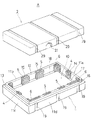
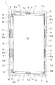
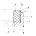
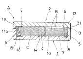
図1は本発明にかかる板状体の搬送用容器の分離した容器本体と蓋体の斜視図、図2は容器本体の平面図、図3は前図の一部の拡大平面図、図4は当接部材の付設部分の装着前の拡大斜視図、図5及び図6は同部分の当接部材の装着状態の断面図、図7はスペーサー用の保護シートを介して重ねた板状体を収納し蓋体を被せた断面図、図8は同上の一部の拡大断面図である。 1 is a perspective view of a container body and a lid body separated from a plate-like conveyance container according to the present invention, FIG. 2 is a plan view of the container body, FIG. 3 is a partially enlarged plan view of the previous figure, and FIG. FIG. 5 and FIG. 6 are cross-sectional views of the abutting member mounted in the same part, FIG. 7 is a plate-like body stacked via a spacer protection sheet. FIG. 8 is a partial enlarged cross-sectional view of the above.
この搬送用容器Aは、図1に示すように、上方に開口し、収納対象のガラス基板等の板状体Bを、各板状体間にスペーサー用の保護シートCを介して重ねて収納できる平面矩形の容器本体1と、該容器本体1の開口部1aに被着される蓋体2とからなる。
As shown in FIG. 1, the transport container A is opened upward, and a plate-like body B such as a glass substrate to be stored is stacked between each plate-like body via a protective sheet C for spacers. It consists of a flat
容器本体1は、主として緩衝性のある合成樹脂発泡体により成形されてなり、底部10より立ち上がった四周の各側壁11a,11b,11c,11dにより収納部空間が形成されている。前記収納部空間は、収納対象の板状体Bより縦横の寸法がやや大きくやや広い面積で、前記のように保護シートCを介して重ねた所要数枚の板状体Bを収納できる深さに形成されている。通常、板状体Bの厚みによっても異なるが、例えば厚み2〜5mmのガラス基板等の板状体Bの場合、10〜数10枚程度を収納できるように比較的浅く形成される。
The
また、蓋体2は、容器本体1と同様の緩衝性のある合成樹脂発泡体により成形されてなり、前記容器本体の開口部1aに対する被着手段として、図の場合、前記容器本体1の開口部1aには、内側に凸縁12を残して外側に切欠段部13が形成されており、前記蓋体2の下面側周縁部に突設された嵌合部21が前記凸縁12の外側に嵌合するように形成されている。
Further, the
そして、前記容器本体1の側壁内面には、収納される板状体Bの端縁部が弾力的に当接する緩衝固定用の当接部材4,5,6が、該板状体Bの面方向の動きを抑制できる複数個所に付設されている。具体的には、四方の側壁11a,11b,11c,11dのうち、少なくとも一方向の相対向する側壁11a,11c又は11b,11d、好ましくは図のように、縦横両方向のそれぞれ相対向する側壁11a,11c及び11b,11dの内面に、前記板状体Bの面方向の動きを抑止できるように前記当接部材4,5,6が側壁内面より突出して付設されている。この当接部材4,5,6の突出寸法は、収納される板状体Bを端縁部が当接することで所定位置に位置決めできるように設定される。
Further, on the inner surface of the side wall of the
図の場合は、短辺側の側壁11a,11cの内面には、中央部に一つの当接部材4が付設され、また長辺側の側壁11b,11dの内面には、長手方向の中央部に間隔をおいて2個所に当接部材5が付設され、さらに、四隅部における隣接する両側壁の内面には、短辺側の側壁11a又は11cと、長辺側の側壁11b又は11dとに連続する平面L字形をなす当接部材6が付設されている。
In the case of the figure, a
これらの緩衝固定用の当接部材4,5,6の配置位置や個数、幅や形状等については、図示する実施例のものには限らず、収納した板状体Bの動き規制に効果のある範囲で種々の実施が可能であり、四隅部の当接部材5を省略して、各辺の当接部材4,5のみを配して実施することも、また各辺の当接部材4,5を省略して四隅部の当接部材6のみを配して実施することもできる。
The arrangement position, number, width, shape, etc. of the
前記各当接部材4,5,6は、これに当接する板状体Bに対してある程度の緩衝性を発揮できる弾力性を有する材料が用いられるが、特に本発明の場合は、容器本体1に比して低弾力性を呈する高密度の材料よりなる。この高密度の材料としては、前記容器本体1と同種又は同系の合成樹脂発泡体で、特に容器本体1に比して低倍発泡による高密度の合成樹脂発泡体を好適に用いることができる。
Each of the
このほか、容器本体1と異種材料で弾力性の低い高密度のもの、例えば異種の合成樹脂発泡体を用いるほか、非発泡の弾力性のある合成樹脂やゴム材を用いることもできる。
In addition, a high-density material having a low elasticity and a material different from that of the container
前記当接部材4,5,6を側壁内面に付設するための手段としては、接着剤や両面接着テープを用いる接着手段又は嵌合手段等の種々の装着手段を利用できるが、本発明では、図示する実施例のように、前記当接部材4,5,6の付設個所の側壁内面に、或いは該側壁内面と底面の双方に連続して、該当接部材4,5,6を上方より挿入し嵌合できる凹部14,15,16を形成し、該凹部14,15,16に前記当接部材4,5,6を嵌合して装着する。これにより、該当接部材4,5,6の組込み操作や取り換えが容易になり好ましい。
As means for attaching the
図4〜図6は、当接部材14の付設部分の装着前と装着状態を拡大して示しており、同図に示すように、該当接部材4を装着するための前記凹部14が側壁内面から底面に連続して形成されており、該凹部14に前記当接部材4の背面側部分及び下面側部分が嵌合されることにより、安定性のよい装着状態が保持されるようになっている。他の当接部材5及び6の装着のための凹部15及び16についても、前記同様に形成しておくことで、安定性の良い装着状態を得ることができる。また、前記の嵌合手段と接着手段を併用し、前記当接部材4,5,6を前記凹部14,15,16に嵌合した状態で接着することも可能である。
4 to 6 show an enlarged view of the attachment portion of the
さらに、前記凹部14,15,16の内部を開口幅より広幅に形成するとともに、これに嵌合する当接部材4,5,6の背面側や下面側の嵌合部分を前記凹部との対応形状に形成しておいて、該当接部材4,5,6を容易に抜脱させずに装着できる構造にして実施することもできる。
Further, the inside of the
本発明では、前記のように、嵌合手段により前記当接部材4,5,6を前記凹部14,15,16に嵌合する場合において、前記当接部材4,5,6の背面とこれに対向する前記凹部14,15,16の内面との少なくとも一方、例えば図のように、凹部14,15,16の内面に、他方の当接部材4,5,6と部分的に接することにより、該当接部材4,5,6の背面と凹部14,15,16の内面との間に図のように間隙を保有し該当接部材4,5,6の容器外方への変位を許容するように前記当接部材4,5,6を受支する凸部14a,15a,16aを設けておき、収納されている板状体Bの重量により外方向きの圧力を受けたときに、該凸部14a,15a,16a或いは該凸部の当接部分が弾性変形し易くなり、前記当接部材4,5,6が前記空隙の範囲内で外方へ弾力的に変位できるように形成しておくものとする。すなわち、前記当接部材4,5,6が外方へ弾力的に変位できる構成にしたことで、板状体Bから当接部材4,5,6に作用する圧力を吸収でき衝撃緩和の効果を高めることができ、さらに容器本体1の製作上の寸法誤差或いは経時的な収縮を許容できることにもなる。前記凸部14a,15a,16aの高さは、例えば5mm前後とする。
In the present invention, as described above, In no event to fit the
前記凸部14a,15a,16aは、その形状や配置は任意に設定できるが、図のように断面円弧状の縦リブであるのが、前記当接部材4,5,6を側壁内面の凹部14,15,16に対し例えば上方より挿入するようにして容易に嵌合できるとともに、板状体Bの重量による圧力が作用した時は外方へ容易に弾性変形できることになり好ましい。
The
図示する実施例の場合、前記容器本体1の底部10における周辺部の一部、例えば図のように、短辺側の両側壁11a,11cに沿う部分、及び長辺側の一つの側壁11bに沿う部分に、収納する板状体Bの収納操作及び取り出し操作のための係止部材(図示せず)を、前記底部11に重ねて置かれた板状体Bの下にまで挿し込むための切欠凹部17,18が設けられている。そして、前記切欠凹部17,18が存する側では、収納された板状体Bの端縁部と、側壁11a,11c又は11bの内面との間に、前記係止部材の挿し込みを許容できる間隔S1又はS2を保有できるように、前記当接部材4,5,6の突出高さが設定されている。
In the case of the illustrated embodiment, a part of the peripheral portion of the
また、前記容器本体1及び蓋体2の外面には、容器本体1の内部に板状体Bを収納し蓋体2を被着した状態でバンド掛けするための複数の凹溝19,29が上下対応位置に形成されている。
The outer surfaces of the
なお、図示を省略しているが、前記容器本体1の底部10の上面には、必要に応じて縦横の少なくも一方向の凹溝を形成して区画した凹凸面とすることもできる。
In addition, although illustration is abbreviate | omitted, it can also be set as the uneven surface divided into the upper surface of the
なお、前記容器本体1及び蓋体2の構成材料としては、スチレン改質ポリオレフィン系樹脂、ポリスチレン、ハイインパクトポリスチレン、スチレン−エチレン共重合体、スチレン−無水マレイン酸共重合体、スチレン−アクリロニトリル共重合体等のポリスチレン系樹脂、ポリエチレン、ポリプロピレン、エチレン−酢酸ビニル共重合体等のポリオレフィン系樹脂、ポリエチレンテレフタレート等のポリエステル系樹脂等の各種合成樹脂の発泡体を用いることができる。中でも、スチレン改質ポリオレフィン系樹脂のビーズ発泡体による成形体が好適に用いられる。スチレン改質ポリオレフィン系樹脂は、ポリオレフィン系樹脂粒子にスチレン系単量体を含浸重合させて得られるものであり、スチレン改質ポリオレフィン系樹脂の中でも、スチレン改質ポリエチレン樹脂が好ましく、例えば、スチレン成分の割合は40〜90重量%、好ましくは50〜85重量%、さらに好ましくは55〜75重量%のものが用いられる。また、前記発泡体の発泡倍率は3〜50倍が好ましい。
In addition, as a constituent material of the said container
スチレン改質ポリオレフィン系樹脂のビーズ発泡体の成形品は、同じ発泡倍率のポリプロピレン系樹脂ビーズの成形品に比べて強度があり、また、容器成形後の収縮率が低く寸法精度もよい。さらに、スチレン系樹脂ビーズの発泡成形品に比べて擦れによる粉が出難い長所もある。 A molded product of a styrene-modified polyolefin resin bead foam has strength compared to a molded product of polypropylene resin beads having the same expansion ratio, and has a low shrinkage ratio after molding of the container and good dimensional accuracy. Furthermore, there is an advantage that powder due to rubbing is less likely to be produced as compared with foamed molded products of styrene resin beads.
前記緩衝固定用の当接部材4,5,6の材料としても、容器本体1に使用する前記材料と同じ材料を使用することができる。この場合、前記当接部材4,5,6については容器本体1よりも発泡倍率を低くして高密度の発泡体にする。特に、容器本体1と同種の材料を用いる場合は、ビーズ発泡成形において、部分的に発泡倍率を異にする成形法を利用して、前記当接部材4,5,6に相当する部分を容器本体1より低倍率で発泡させることにより、容器本体1と一体に成形できることになる。
The same material as the material used for the container
この搬送用容器Aによれば、素板ガラス、液晶表示用のガラス基板等の板状体Bを収納する際、先ず、内部の底部10上にスペーサー用の保護シートCを置き、その上に板状体Bと前記保護シートCと交互に重ねて収納する。なお、前記保護シートCとしては、柔軟性のある軟質合成樹脂の発泡シート、例えばポリオレフィン系樹脂の発泡シートが好適に使用される。この発泡シートの厚みは、収納する板状体Bの厚みや種類によっても異なるが、通常、0.2〜5.0mmの厚みのものが好適に使用される。
According to this transport container A, when the plate-like body B such as the base plate glass and the glass substrate for liquid crystal display is stored, first, the protective sheet C for the spacer is placed on the
前記のように板状体Bと保護シートCと交互に重ねて収納する際、各板状体Bの端面を容器本体1の側壁11a,11b,11c,11dの内面に有する当接部材4,5,6に当接させて位置決めし面方向の動きを規制するように収納する。この後、前記容器本体1の開口部1aに蓋体2を被着し、搬送用容器Aの全体をベルト掛けして輸送に供する。
When the plate-like body B and the protective sheet C are alternately stacked and stored as described above, the
この輸送において、内部に収納した板状体Bの全体を広い面で受けることで、板状体Bの曲げ変形の虞がないばかりか、各板状体Bの端面を側壁内面の当接部材3,4,5に当接させることで、該板状体Bを側壁内面から離して支持でき、輸送中の振動等による面方向の動きを規制できる。そして、輸送中の取り扱いにおいて、例えば容器の横倒しや斜め落下等のために、収納されている板状体Bの重量により前記端面から前記当接部材4,5,6に圧力が集中して作用することになるが、前記当接部材4,5,6は容器本体1よりも弾力性の低い高密度材料により形成されているために、該当接部材4,5,6が前記圧力を受けても過度に圧縮変形したり破損する虞がない。その上、前記圧力を受けた前記当接部材4,5,6を、これよりも低密度の合成樹脂発泡体よりなる容器本体1の側壁により弾力的に受支することになるため、前記のように当接部材4,5,6自体が弾力性の低いものであっても、優れた緩衝効果を発揮できる。
In this transportation, the entire plate-like body B housed inside is received by a wide surface, so that there is no risk of bending deformation of the plate-like body B, and the end surface of each plate-like body B is a contact member of the inner surface of the side wall. By abutting on 3, 4, and 5, the plate-like body B can be supported away from the inner surface of the side wall, and movement in the surface direction due to vibration during transportation can be restricted. In handling during transportation, for example, due to the weight of the plate-like body B accommodated, the pressure concentrates on the
本発明の搬送用容器は、素板ガラス、液晶表示用やプラズマ表示用のガラス基板等の比較的大型のガラス基板その他の衝撃に弱い各種の板状体を搬送、保管するのに好適に利用できる。 The transport container of the present invention can be suitably used for transporting and storing relatively large glass substrates such as glass plates for glass, liquid crystal displays and plasma displays, and other various plate-like bodies that are vulnerable to impact. .
A…搬送用容器、B…板状体、C…保護シート、1…容器本体、1a…開口部、2…蓋体、4,5,6…当接部材、10…底部、11a,11b,11c,11d…側壁、12…凸縁、13…切欠段部、14,15,16…凹部、17,18…切欠凹部、19,29…凹溝、S1,S2…間隔。 A ... container for conveyance, B ... plate-like body, C ... protective sheet, 1 ... container body, 1a ... opening, 2 ... lid, 4, 5, 6 ... contact member, 10 ... bottom, 11a, 11b, 11c, 11d ... sidewall, 12 ... convex edge, 13 ... notch step, 14, 15, 16 ... recess, 17, 18 ... notch recess, 19, 29 ... recess, S1, S2 ... spacing.
Claims (5)
前記容器本体の側壁内面の複数個所に、収納される板状体の端部が当接する緩衝固定用の当接部材が側壁内面より突出して付設され、該当接部材が容器本体よりも高密度の材料により形成され、該当接部材が容器本体の側壁内面に有する凹部に嵌合して付設され、該当接部材の背面とこれに対向する凹部内面との少なくとも一方に、他方と部分的に接して該当接部材の背面と凹部内面との間に間隙を保有し該当接部材の容器外方への変位を許容する凸部が設けられてなることを特徴とする板状体の搬送用容器。 A synthetic resin foam container consisting of a container body that opens upward and a lid that is attached to the opening of the container body, with a plurality of plate-like bodies sandwiching a protective sheet between each plate-like body It is a container for transporting a plate-like body to be stored in a stacked state,
Buffer fixing contact members that contact the end portions of the plate-like bodies to be stored are provided at a plurality of locations on the inner surface of the side wall of the container body so as to protrude from the inner surface of the side wall . It is made of a material , and the corresponding contact member is fitted and attached to a concave portion on the inner surface of the side wall of the container body, and at least one of the rear surface of the corresponding contact member and the inner surface of the concave portion facing this is partially in contact with the other A container for transporting a plate-like body, characterized in that a convex portion is provided between the back surface of the abutting member and the inner surface of the concave portion to allow a displacement of the corresponding contact member to the outside of the container.
Priority Applications (1)
| Application Number | Priority Date | Filing Date | Title |
|---|---|---|---|
| JP2008118901A JP5259243B2 (en) | 2008-04-30 | 2008-04-30 | Container for transporting plate-shaped body |
Applications Claiming Priority (1)
| Application Number | Priority Date | Filing Date | Title |
|---|---|---|---|
| JP2008118901A JP5259243B2 (en) | 2008-04-30 | 2008-04-30 | Container for transporting plate-shaped body |
Publications (2)
| Publication Number | Publication Date |
|---|---|
| JP2009269610A JP2009269610A (en) | 2009-11-19 |
| JP5259243B2 true JP5259243B2 (en) | 2013-08-07 |
Family
ID=41436535
Family Applications (1)
| Application Number | Title | Priority Date | Filing Date |
|---|---|---|---|
| JP2008118901A Active JP5259243B2 (en) | 2008-04-30 | 2008-04-30 | Container for transporting plate-shaped body |
Country Status (1)
| Country | Link |
|---|---|
| JP (1) | JP5259243B2 (en) |
Families Citing this family (27)
| Publication number | Priority date | Publication date | Assignee | Title |
|---|---|---|---|---|
| KR101633117B1 (en) * | 2009-12-18 | 2016-06-23 | 엘지디스플레이 주식회사 | Container of packaging liquid crystall display panel module and packaging method thereof |
| JP5649923B2 (en) * | 2010-11-18 | 2015-01-07 | 積水化成品工業株式会社 | Container for transporting plate-shaped body |
| JP5998533B2 (en) * | 2012-03-09 | 2016-09-28 | 日立化成株式会社 | Adhesive film packaging box and adhesive film packaging set |
| CN102616469A (en) * | 2012-04-11 | 2012-08-01 | 深圳市华星光电技术有限公司 | Packing box for liquid crystal display panel and liquid crystal display panel components and application method thereof |
| CN102616488B (en) * | 2012-04-13 | 2014-04-02 | 深圳市华星光电技术有限公司 | Liquid crystal glass packaging box |
| US8777007B2 (en) | 2012-04-13 | 2014-07-15 | Shenzhen China Star Optoelectronics Technology Co., Ltd. | Packaging box for liquid crystal glass |
| CN102795422B (en) | 2012-09-11 | 2016-09-07 | 深圳市华星光电技术有限公司 | Liquid-crystalline glasses panel package structure |
| CN102910379B (en) * | 2012-11-16 | 2015-04-01 | 深圳市华星光电技术有限公司 | Liquid crystal glass packing container |
| US8789698B2 (en) | 2012-11-16 | 2014-07-29 | Shenzhen China Star Optoelectronics Technology Co., Ltd | Package box of liquid crystal glass |
| JP2014193738A (en) * | 2013-03-29 | 2014-10-09 | Sekisui Plastics Co Ltd | Container for panel transportation |
| KR200477573Y1 (en) * | 2013-04-19 | 2015-06-25 | (주)우신특수포장 | Assembly type tray for carriage |
| CN103193022B (en) * | 2013-04-24 | 2016-02-10 | 深圳市华星光电技术有限公司 | A kind of liquid-crystalline glasses packing device of waterproof |
| KR101426898B1 (en) | 2013-12-06 | 2014-08-05 | 주식회사 성곡 | Tray assembly for display pannel transporting |
| JP2015141290A (en) * | 2014-01-28 | 2015-08-03 | ブラザー工業株式会社 | Package, and method of recovering cartridge |
| CN104185415B (en) * | 2014-08-21 | 2018-01-16 | 昆山龙腾光电有限公司 | Substrate positioning carrier, substrate assembling system and substrate method for assembling |
| CN104192444B (en) * | 2014-09-02 | 2016-06-08 | 深圳市华星光电技术有限公司 | Liquid crystal panel tr |
| CN104443799B (en) * | 2014-10-24 | 2017-10-17 | 深圳市华星光电技术有限公司 | A kind of liquid-crystalline glasses packing case and packing method |
| CN105173333B (en) * | 2015-09-25 | 2017-04-05 | 武汉华星光电技术有限公司 | Glass substrate packing box |
| JP3201500U (en) * | 2015-09-29 | 2015-12-10 | 積水化成品工業株式会社 | Packing material and package |
| CN105366218A (en) * | 2015-12-09 | 2016-03-02 | 深圳市华星光电技术有限公司 | Liquid crystal panel packaging box and forming method thereof |
| WO2018163299A1 (en) * | 2017-03-07 | 2018-09-13 | 堺ディスプレイプロダクト株式会社 | Storing container |
| JP3210846U (en) * | 2017-03-29 | 2017-06-08 | 積水化成品工業株式会社 | Panel transport container |
| JP7063927B2 (en) * | 2020-03-02 | 2022-05-09 | シャープ株式会社 | Containers and protective members |
| CN111897166B (en) * | 2020-07-31 | 2021-02-12 | 深圳亿成光电科技有限公司 | Ultra-thin type leak protection light LCM module |
| DE102020130292A1 (en) * | 2020-11-17 | 2022-05-19 | Schott Ag | Process for packaging and unpacking flat substrates and packaging for flat substrates |
| CN113942236B (en) * | 2021-10-14 | 2024-03-08 | 京东方科技集团股份有限公司 | Tray assembly and automatic laminating device |
| JP7476253B2 (en) | 2022-04-28 | 2024-04-30 | 堺ディスプレイプロダクト株式会社 | container |
Family Cites Families (4)
| Publication number | Priority date | Publication date | Assignee | Title |
|---|---|---|---|---|
| JPH0480889U (en) * | 1990-11-28 | 1992-07-14 | ||
| JP3325385B2 (en) * | 1994-03-28 | 2002-09-17 | 淀川ヒューテック株式会社 | Glass substrate transport box |
| JP3120707U (en) * | 2006-01-16 | 2006-04-20 | 陽程科技股▲ふん▼有限公司 | Bearing device with cushion |
| JP4933840B2 (en) * | 2006-05-29 | 2012-05-16 | 株式会社ジェイエスピー | Glass substrate transport box and glass substrate transport package |
-
2008
- 2008-04-30 JP JP2008118901A patent/JP5259243B2/en active Active
Also Published As
| Publication number | Publication date |
|---|---|
| JP2009269610A (en) | 2009-11-19 |
Similar Documents
| Publication | Publication Date | Title |
|---|---|---|
| JP5259243B2 (en) | Container for transporting plate-shaped body | |
| JP5227827B2 (en) | Glass substrate container | |
| CN102991884B (en) | The conveying container of tabular body | |
| JP5162341B2 (en) | Glass substrate transport tray and glass substrate package | |
| JP5649923B2 (en) | Container for transporting plate-shaped body | |
| JP2006273333A (en) | Packing tray | |
| JPH11157595A (en) | LCD panel module packaging structure | |
| JP2011246170A (en) | Container for conveying plate-like body | |
| JP4555127B2 (en) | Parts packaging tray and manufacturing method thereof | |
| JP5340840B2 (en) | Container for transporting plate-shaped body | |
| JP5340769B2 (en) | Buffer packaging material | |
| JP2012062081A (en) | Container for conveying plate | |
| CN203581671U (en) | Reinforcing component and face plate transportation container | |
| JP2010208659A (en) | Shock-absorbing packaging material | |
| JP5406120B2 (en) | Container for transporting plate-shaped body | |
| TWI673215B (en) | Cushioning material | |
| JP2010215262A (en) | Carrying container for glass substrate | |
| JP5701726B2 (en) | Container for transporting plate-shaped body | |
| CN102530422A (en) | Container for transfer of tabular body | |
| JP2009057101A (en) | Plate container | |
| JP2012056611A (en) | Plate shipping container | |
| JP5649924B2 (en) | Plate-shaped container | |
| JP5615595B2 (en) | Container for transporting plate-shaped body | |
| KR200477851Y1 (en) | Reinforcing member and panel transportation vessel | |
| JP5468497B2 (en) | Component packaging tray and package using the same |
Legal Events
| Date | Code | Title | Description |
|---|---|---|---|
| A621 | Written request for application examination |
Free format text: JAPANESE INTERMEDIATE CODE: A621 Effective date: 20110207 |
|
| A977 | Report on retrieval |
Free format text: JAPANESE INTERMEDIATE CODE: A971007 Effective date: 20120921 |
|
| A131 | Notification of reasons for refusal |
Free format text: JAPANESE INTERMEDIATE CODE: A131 Effective date: 20121023 |
|
| A521 | Written amendment |
Free format text: JAPANESE INTERMEDIATE CODE: A523 Effective date: 20121220 |
|
| TRDD | Decision of grant or rejection written | ||
| A01 | Written decision to grant a patent or to grant a registration (utility model) |
Free format text: JAPANESE INTERMEDIATE CODE: A01 Effective date: 20130416 |
|
| A61 | First payment of annual fees (during grant procedure) |
Free format text: JAPANESE INTERMEDIATE CODE: A61 Effective date: 20130424 |
|
| FPAY | Renewal fee payment (event date is renewal date of database) |
Free format text: PAYMENT UNTIL: 20160502 Year of fee payment: 3 |
|
| R150 | Certificate of patent or registration of utility model |
Ref document number: 5259243 Country of ref document: JP Free format text: JAPANESE INTERMEDIATE CODE: R150 Free format text: JAPANESE INTERMEDIATE CODE: R150 |