JP5259174B2 - Transmission / reception system - Google Patents
Transmission / reception system Download PDFInfo
- Publication number
- JP5259174B2 JP5259174B2 JP2007332936A JP2007332936A JP5259174B2 JP 5259174 B2 JP5259174 B2 JP 5259174B2 JP 2007332936 A JP2007332936 A JP 2007332936A JP 2007332936 A JP2007332936 A JP 2007332936A JP 5259174 B2 JP5259174 B2 JP 5259174B2
- Authority
- JP
- Japan
- Prior art keywords
- signal
- reception
- transmission
- frequency
- modulation
- Prior art date
- Legal status (The legal status is an assumption and is not a legal conclusion. Google has not performed a legal analysis and makes no representation as to the accuracy of the status listed.)
- Active
Links
Images


Classifications
-
- A—HUMAN NECESSITIES
- A61—MEDICAL OR VETERINARY SCIENCE; HYGIENE
- A61B—DIAGNOSIS; SURGERY; IDENTIFICATION
- A61B1/00—Instruments for performing medical examinations of the interior of cavities or tubes of the body by visual or photographical inspection, e.g. endoscopes; Illuminating arrangements therefor
- A61B1/04—Instruments for performing medical examinations of the interior of cavities or tubes of the body by visual or photographical inspection, e.g. endoscopes; Illuminating arrangements therefor combined with photographic or television appliances
- A61B1/041—Capsule endoscopes for imaging
-
- A—HUMAN NECESSITIES
- A61—MEDICAL OR VETERINARY SCIENCE; HYGIENE
- A61B—DIAGNOSIS; SURGERY; IDENTIFICATION
- A61B1/00—Instruments for performing medical examinations of the interior of cavities or tubes of the body by visual or photographical inspection, e.g. endoscopes; Illuminating arrangements therefor
- A61B1/00002—Operational features of endoscopes
- A61B1/00011—Operational features of endoscopes characterised by signal transmission
- A61B1/00016—Operational features of endoscopes characterised by signal transmission using wireless means
-
- A—HUMAN NECESSITIES
- A61—MEDICAL OR VETERINARY SCIENCE; HYGIENE
- A61B—DIAGNOSIS; SURGERY; IDENTIFICATION
- A61B5/00—Measuring for diagnostic purposes; Identification of persons
- A61B5/06—Devices, other than using radiation, for detecting or locating foreign bodies ; Determining position of diagnostic devices within or on the body of the patient
- A61B5/061—Determining position of a probe within the body employing means separate from the probe, e.g. sensing internal probe position employing impedance electrodes on the surface of the body
- A61B5/062—Determining position of a probe within the body employing means separate from the probe, e.g. sensing internal probe position employing impedance electrodes on the surface of the body using magnetic field
Landscapes
- Health & Medical Sciences (AREA)
- Life Sciences & Earth Sciences (AREA)
- Surgery (AREA)
- Engineering & Computer Science (AREA)
- Medical Informatics (AREA)
- Molecular Biology (AREA)
- Pathology (AREA)
- Veterinary Medicine (AREA)
- Public Health (AREA)
- Biophysics (AREA)
- Biomedical Technology (AREA)
- Heart & Thoracic Surgery (AREA)
- Physics & Mathematics (AREA)
- General Health & Medical Sciences (AREA)
- Animal Behavior & Ethology (AREA)
- Optics & Photonics (AREA)
- Nuclear Medicine, Radiotherapy & Molecular Imaging (AREA)
- Radiology & Medical Imaging (AREA)
- Computer Networks & Wireless Communication (AREA)
- Human Computer Interaction (AREA)
- Endoscopes (AREA)
- Measurement Of The Respiration, Hearing Ability, Form, And Blood Characteristics Of Living Organisms (AREA)
- Position Fixing By Use Of Radio Waves (AREA)
- Digital Transmission Methods That Use Modulated Carrier Waves (AREA)
Description
本発明は、送信装置と受信装置との無線通信によって各種データを送受信する送受信システムに関し、特に、広帯域の無線通信を行って画像データ等の各種データを送受信するとともに、データを受信した際の受信電界強度を検出する送受信システムに関するものである。 The present invention relates to a transmission / reception system that transmits and receives various types of data by wireless communication between a transmission device and a reception device, and in particular, transmits and receives various types of data such as image data by performing broadband wireless communication, and reception when data is received. The present invention relates to a transmission / reception system for detecting electric field strength.
従来から、内視鏡の分野において、カプセル型の筐体内部に撮像機能と無線通信機能とを備えたカプセル型内視鏡が登場し、撮像した画像データを無線送信するカプセル型内視鏡(送信装置の一例)と被検体外部の受信装置とを用いた送受信システムが提案されている。この送受信システムにおいて、カプセル型内視鏡は、観察(検査)のために患者等の被検体によって経口摂取され、その後、この被検体から自然排出されるまでの間、消化管内部を蠕動運動等によって移動しつつ所定間隔(例えば0.5秒間隔)で臓器内部の画像(以下、体内画像という場合がある)を順次撮像する。かかるカプセル型内視鏡は、被検体内部において体内画像を撮像する都度、この体内画像データを外部に順次無線送信する。 Conventionally, in the field of endoscopes, capsule endoscopes having an imaging function and a wireless communication function have appeared in a capsule-type housing, and capsule endoscopes that wirelessly transmit captured image data ( A transmission / reception system using an example of a transmission device and a reception device outside a subject has been proposed. In this transmission / reception system, the capsule endoscope is orally ingested by a subject such as a patient for observation (examination) and then peristally moves inside the digestive tract until it is naturally discharged from the subject. The images inside the organ (hereinafter sometimes referred to as in-vivo images) are sequentially imaged at predetermined intervals (for example, at intervals of 0.5 seconds) while moving. Such a capsule endoscope sequentially transmits the in-vivo image data to the outside in sequence every time an in-vivo image is captured inside the subject.
かかる被検体内部のカプセル型内視鏡によって無線送信された体内画像データは、この被検体外部の受信装置によって順次受信される。受信装置は、被検体の体表上に配置された複数の受信アンテナを介してカプセル型内視鏡からの無線信号を受信し、この受信した無線信号に対して所定の復調処理等を行って被検体の体内画像データを取得する。かかる受信装置に受信された体内画像データは、この受信装置に挿着された記録媒体に順次保存される。その後、かかる受信装置内の記録媒体は、受信装置から取り出されて画像表示装置に挿着される。画像表示装置は、この挿着した記録媒体から体内画像データ群を取り込んでメモリに記憶するとともに、体内画像データ群に基づく体内画像群をディスプレイ等に表示する。医師または看護師等のユーザは、かかる画像表示装置に表示された体内画像群を観察して被検体を診断する。 The in-vivo image data wirelessly transmitted by the capsule endoscope inside the subject is sequentially received by the receiving device outside the subject. The receiving device receives a radio signal from the capsule endoscope via a plurality of receiving antennas arranged on the body surface of the subject, and performs predetermined demodulation processing or the like on the received radio signal. In-vivo image data of a subject is acquired. The in-vivo image data received by the receiving device is sequentially stored in a recording medium inserted in the receiving device. Thereafter, the recording medium in the receiving apparatus is taken out from the receiving apparatus and inserted into the image display apparatus. The image display apparatus captures the in-vivo image data group from the inserted recording medium and stores it in the memory, and displays the in-vivo image group based on the in-vivo image data group on a display or the like. A user such as a doctor or a nurse diagnoses a subject by observing the in-vivo image group displayed on the image display device.
なお、このように画像データ等の各種データを無線通信によって送受信する送受信システムには、アンテナを介して受信した受信信号を信号強度検出系と信号処理系とに分け、この受信信号の信号強度を信号強度検出系によって検出し、この受信信号に対する所定の信号処理を信号処理系によって行うものがある(例えば、特許文献1,2参照)。
In such a transmission / reception system that transmits and receives various data such as image data by wireless communication, the received signal received via the antenna is divided into a signal strength detection system and a signal processing system, and the signal strength of this received signal is determined. Some of them are detected by a signal strength detection system, and predetermined signal processing for the received signal is performed by the signal processing system (see, for example,
ところで、上述した従来の送受信システムにおいて、被検体外部の受信装置は、複数の受信アンテナを介してカプセル型内視鏡から体内画像を受信するとともに、この体内画像を受信した際の電波強度(すなわち受信電界強度)を受信アンテナ毎に検出する。なお、かかる各受信アンテナの受信電界強度は、例えば体内画像を撮像した際のカプセル型内視鏡の体内位置情報を検出(算出)する等のアプリケーションに用いられる重要なパラメータである。 By the way, in the above-described conventional transmission / reception system, the receiving device outside the subject receives the in-vivo image from the capsule endoscope via the plurality of receiving antennas, and the radio wave intensity at the time of receiving the in-vivo image (that is, The received electric field intensity) is detected for each receiving antenna. The received electric field strength of each receiving antenna is an important parameter used in an application such as detecting (calculating) in-vivo position information of a capsule endoscope when an in-vivo image is captured.
しかしながら、上述した従来の送受信システムでは、被検体内部のカプセル型内視鏡と被検体外部の受信装置との間で体内画像データを順次送受信するという観点から、通常、高速データ通信に有利な広帯域(例えば数MHzの周波数帯域幅)の無線通信が行われるため、この無線通信の広帯域化に伴って受信装置の帯域通過フィルタの周波数帯域幅が増加し、この周波数帯域幅の増加に伴ってノイズレベルが増加するとともに受信装置の受信電界強度の検出下限値が上昇し、これに起因して、受信アンテナ毎の受信電界強度の検出、特に、低レベルの受信電界強度の検出が不安定になるという問題点があった。 However, in the above-described conventional transmission / reception system, a wideband that is usually advantageous for high-speed data communication from the viewpoint of sequentially transmitting and receiving in-vivo image data between a capsule endoscope inside the subject and a receiving device outside the subject. Since wireless communication (for example, a frequency bandwidth of several MHz) is performed, the frequency bandwidth of the band-pass filter of the receiving device increases with the increase in the bandwidth of the wireless communication, and noise increases with the increase in the frequency bandwidth. As the level increases, the detection lower limit value of the reception electric field strength of the reception device increases, and as a result, detection of reception electric field strength for each reception antenna, particularly detection of low-level reception electric field strength becomes unstable. There was a problem.
本発明は、上記事情に鑑みてなされたものであって、データを受信した際の受信電界強度を受信アンテナ毎に安定して検出することができる送受信システムを提供することを目的とする。 The present invention has been made in view of the above circumstances, and an object of the present invention is to provide a transmission / reception system capable of stably detecting the reception electric field strength when data is received for each reception antenna.
上述した課題を解決し、目的を達成するために、本発明にかかる送受信システムは、広帯域信号成分と狭帯域信号成分とによって構成される変調信号を生成し、該変調信号を外部に送信する送信装置と、信号処理系と受信強度検出系とを具備し、3以上の受信アンテナを介して前記変調信号を受信し、受信した前記変調信号に含まれる広帯域信号成分を前記信号処理系によって処理し、前記変調信号に含まれる狭帯域信号成分を前記受信強度検出系によって処理する受信装置と、を備えたことを特徴とする。 In order to solve the above-described problems and achieve the object, a transmission / reception system according to the present invention generates a modulation signal composed of a wideband signal component and a narrowband signal component, and transmits the modulation signal to the outside. An apparatus, a signal processing system, and a received intensity detection system, receiving the modulated signal via three or more receiving antennas, and processing the broadband signal component included in the received modulated signal by the signal processing system. And a receiving device that processes a narrowband signal component included in the modulated signal by the reception intensity detection system.
また、本発明にかかる送受信システムは、上記の発明において、前記送信装置は、周波数を固定した特定信号を含む信号区間と所定のデータを含むデータ区間とを有する送信信号を生成し、該送信信号をデジタル変調して前記信号区間に前記特定信号に対応する前記狭帯域信号成分を含む前記変調信号を生成し、この生成した前記変調信号を外部に無線送信し、前記受信装置は、前記3以上の受信アンテナを介して前記変調信号を受信して前記受信強度検出系と前記信号処理系とに前記変調信号を分岐し、この分岐した一方の変調信号の信号区間に含まれる前記狭帯域信号成分を前記受信強度検出系の狭帯域フィルタによって抽出して前記狭帯域信号成分の受信電界強度を前記受信強度検出系によって検出し、他方の変調信号のデータ区間に含まれる前記所定のデータを前記信号処理系によって信号処理することを特徴とする。 In the transmission / reception system according to the present invention, in the above invention, the transmission device generates a transmission signal having a signal section including a specific signal with a fixed frequency and a data section including predetermined data, and the transmission signal The modulated signal including the narrowband signal component corresponding to the specific signal in the signal section, and wirelessly transmitting the generated modulated signal to the outside. The modulated signal is received via a receiving antenna, and the modulated signal is branched into the received intensity detection system and the signal processing system, and the narrowband signal component included in the signal section of the branched one of the modulated signals Is extracted by the narrow band filter of the reception intensity detection system, and the reception electric field intensity of the narrow band signal component is detected by the reception intensity detection system, and the data area of the other modulation signal is detected. Characterized by signal processing Murrell said predetermined data by the signal processing system.
また、本発明にかかる送受信システムは、上記の発明において、前記送信装置は、前記信号区間に直流信号である前記特定信号を含み且つ前記データ区間に前記所定のデータを含む前記送信信号を生成する信号生成部と、前記信号生成部によって生成された前記送信信号をデジタル変調して、搬送波周波数成分である前記狭帯域信号成分を前記信号区間に含む前記変調信号を生成する変調部と、前記変調部によって生成された前記変調信号を前記受信装置に無線送信する送信部と、を備えたことを特徴とする。 In the transmission / reception system according to the present invention as set forth in the invention described above, the transmission device generates the transmission signal including the specific signal that is a direct current signal in the signal section and the predetermined data in the data section. A signal generation unit; a modulation unit that digitally modulates the transmission signal generated by the signal generation unit to generate the modulation signal including the narrowband signal component that is a carrier frequency component in the signal section; and the modulation A transmitter that wirelessly transmits the modulated signal generated by the receiver to the receiver.
また、本発明にかかる送受信システムは、上記の発明において、前記デジタル変調は、周波数偏移変調であることを特徴とする。 In the transmission / reception system according to the present invention as set forth in the invention described above, the digital modulation is frequency shift keying.
また、本発明にかかる送受信システムは、上記の発明において、前記送信装置は、搬送波周波数に対する周波数偏移の2倍に等しい周波数に固定したデジタル信号である前記特定信号を前記信号区間に含み且つ前記データ区間に前記所定のデータを含む前記送信信号を生成する信号生成部と、前記信号生成部によって生成された前記送信信号を最小偏移変調して、少なくとも搬送波周波数成分を含む複数の前記狭帯域信号成分を前記信号区間に有する前記変調信号を生成する変調部と、前記変調部によって生成された前記変調信号を前記受信装置に無線送信する送信部と、を備えたことを特徴とする。 In the transmission / reception system according to the present invention as set forth in the invention described above, the transmission device includes the specific signal, which is a digital signal fixed to a frequency equal to twice a frequency shift with respect to a carrier frequency, in the signal section, and A signal generator for generating the transmission signal including the predetermined data in a data section; and a plurality of the narrowbands including at least a carrier frequency component by performing minimum shift keying on the transmission signal generated by the signal generator A modulation unit that generates the modulation signal having a signal component in the signal section, and a transmission unit that wirelessly transmits the modulation signal generated by the modulation unit to the reception device.
また、本発明にかかる送受信システムは、上記の発明において、前記信号生成部は、前記信号区間の後段に高レベルおよび低レベルのデジタルデータを繰り返すデジタル信号を含むアイドリング区間を有し、且つ該アイドリング区間の後段に前記データ区間を有する前記送信信号を生成することを特徴とする。 In the transmission / reception system according to the present invention as set forth in the invention described above, the signal generator has an idling section including a digital signal that repeats high-level and low-level digital data after the signal section. The transmission signal having the data section in the subsequent stage of the section is generated.
また、本発明にかかる送受信システムは、上記の発明において、前記信号生成部は、前記データ区間の後段に前記特定信号と同じ直流信号を含むガード区間を有し、且つ該ガード区間の後段に前記信号区間を有する前記送信信号を生成することを特徴とする。 In the transmission / reception system according to the present invention as set forth in the invention described above, the signal generation unit includes a guard section including the same DC signal as the specific signal at a subsequent stage of the data section, and the downstream of the guard section. The transmission signal having a signal section is generated.
また、本発明にかかる送受信システムは、上記の発明において、前記受信強度検出系は、前記狭帯域フィルタによって抽出された前記狭帯域信号成分の受信電界強度を前記受信アンテナ毎に検出する受信強度検出部を備え、前記狭帯域フィルタは、前記狭帯域信号成分と同程度の帯域であって前記一方の変調信号の占有帯域幅に比して狭帯域な通過帯域幅を有することを特徴とする。 In the transmission / reception system according to the present invention as set forth in the invention described above, the reception intensity detection system detects the reception electric field intensity of the narrowband signal component extracted by the narrowband filter for each reception antenna. The narrowband filter is characterized in that the narrowband filter has the same bandwidth as the narrowband signal component and a narrower passband than the occupied bandwidth of the one modulation signal.
また、本発明にかかる送受信システムは、上記の発明において、前記受信強度検出部は、前記3以上の受信アンテナを介して前記変調信号を受信してから所定の時間が経過するまでに前記一方の変調信号を検出し、前記一方の変調信号を検出してから所定の時間が経過後に前記狭帯域信号成分の受信電界強度を検出することを特徴とする。 In the transmission / reception system according to the present invention as set forth in the invention described above, the reception intensity detection unit may receive the modulated signal through the three or more reception antennas until a predetermined time elapses. A modulation signal is detected, and the received electric field strength of the narrowband signal component is detected after a predetermined time has elapsed since the one modulation signal was detected.
また、本発明にかかる送受信システムは、上記の発明において、前記受信装置は、前記3以上の受信アンテナを介して受信した前記変調信号の占有帯域幅と同程度の通過帯域幅を有する広帯域フィルタを備え、前記狭帯域フィルタは、前記広帯域フィルタの1/10000以上、1/10以下の通過帯域幅を有することを特徴とする。 In the transmission / reception system according to the present invention as set forth in the invention described above, the receiving device includes a wideband filter having a pass bandwidth substantially equal to an occupied bandwidth of the modulated signal received via the three or more receiving antennas. The narrow band filter has a pass bandwidth of 1 / 10,000 or more and 1/10 or less of the wide band filter.
また、本発明にかかる送受信システムは、上記の発明において、前記受信装置は、前記3以上の受信アンテナを介して受信した前記変調信号に異なる周波数の信号を混合して、前記変調信号の周波数を中間周波数に変換し、この変換した前記変調信号を前記受信強度検出系と前記信号処理系とに分岐する周波数混合部を備えたことを特徴とする。 In the transmission / reception system according to the present invention as set forth in the invention described above, the receiving device mixes signals of different frequencies with the modulated signals received via the three or more receiving antennas, and sets the frequency of the modulated signals. A frequency mixing unit is provided that converts the modulated signal into an intermediate frequency and branches the converted modulated signal into the reception intensity detection system and the signal processing system.
また、本発明にかかる送受信システムは、上記の発明において、前記受信装置は、前記3以上の受信アンテナを介して受信した前記変調信号に異なる周波数の信号を混合して、前記変調信号の周波数を中間周波数に変換する周波数混合部と、前記周波数混合部によって中間周波数に変換された前記変調信号を増幅し、この増幅した前記変調信号を前記受信強度検出系と前記信号処理系とに分岐する中間周波数増幅部と、を備えたことを特徴とする。 In the transmission / reception system according to the present invention as set forth in the invention described above, the receiving device mixes signals of different frequencies with the modulated signals received via the three or more receiving antennas, and sets the frequency of the modulated signals. A frequency mixing unit for converting to an intermediate frequency, and an intermediate for amplifying the modulation signal converted to the intermediate frequency by the frequency mixing unit and branching the amplified modulation signal to the reception intensity detection system and the signal processing system And a frequency amplifying unit.
また、本発明にかかる送受信システムは、上記の発明において、前記受信装置は、前記3以上の受信アンテナを介して受信した前記変調信号を増幅し、この増幅した前記変調信号を前記受信強度検出系と前記信号処理系とに分岐する増幅部を備え、前記受信強度検出系は、前記増幅部によって分岐された一方の変調信号に異なる周波数の信号を混合して、該変調信号の周波数を中間周波数に変換し、この変換した該変調信号を前記狭帯域フィルタに出力する第1の周波数混合部を備え、前記信号処理系は、前記増幅部によって分岐された他方の変調信号に異なる周波数の信号を混合して、該変調信号の周波数を中間周波数に変換し、この変換した該変調信号を前記広帯域フィルタに出力する第2の周波数混合部を備えたことを特徴とする。 In the transmission / reception system according to the present invention as set forth in the invention described above, the receiving apparatus amplifies the modulated signal received via the three or more receiving antennas, and the amplified modulation signal is amplified by the reception intensity detection system. And the signal processing system, and the reception intensity detection system mixes one of the modulation signals branched by the amplification section with a signal of a different frequency, and converts the frequency of the modulation signal to an intermediate frequency. And a first frequency mixing unit that outputs the converted modulated signal to the narrowband filter, and the signal processing system applies a signal of a different frequency to the other modulated signal branched by the amplifying unit. A second frequency mixing unit that mixes and converts the frequency of the modulated signal into an intermediate frequency and outputs the converted modulated signal to the broadband filter is provided.
また、本発明にかかる送受信システムは、上記の発明において、前記所定のデータは、被検体の体内データであり、前記送信装置は、前記被検体内部に導入され、前記被検体の体内データを取得し、前記信号区間に前記特定信号を含み且つ前記データ区間に前記体内データを含む前記送信信号を生成し、この生成した前記送信信号をデジタル変調した前記変調信号を無線送信するカプセル型医療装置であることを特徴とする。 In the transmission / reception system according to the present invention as set forth in the invention described above, the predetermined data is in-vivo data of a subject, and the transmitting device is introduced into the subject to acquire in-vivo data of the subject. A capsule-type medical device that generates the transmission signal including the specific signal in the signal section and including the in-vivo data in the data section, and wirelessly transmits the modulated signal obtained by digitally modulating the generated transmission signal. It is characterized by being.
また、本発明にかかる送受信システムは、上記の発明において、前記体内データは、前記被検体内部の画像データであり、前記カプセル型医療装置は、前記被検体内部の画像データを撮像する撮像部を備えたカプセル型内視鏡であることを特徴とする。 In the transmission / reception system according to the present invention as set forth in the invention described above, the in-vivo data is image data inside the subject, and the capsule medical device includes an imaging unit that captures image data inside the subject. It is a capsule endoscope provided.
本発明にかかる送受信システムは、送信装置が、周波数を固定した特定信号を含む信号区間と所定のデータを含むデータ区間とを有する送信信号を生成し、該送信信号をデジタル変調して前記信号区間に前記特定信号に対応する狭帯域信号成分を含む変調信号を生成し、該変調信号を無線送信し、受信装置が、受信強度検出系と信号処理系とを有し、3以上の受信アンテナを介して前記変調信号を受信して前記受信強度検出系と前記信号処理系とに前記変調信号を分岐し、この分岐した一方の変調信号の信号区間に含まれる前記狭帯域信号成分を前記受信強度検出系の狭帯域フィルタによって抽出して前記狭帯域信号成分の受信電界強度を前記受信強度検出系によって検出し、他方の変調信号のデータ区間に含まれる前記所定のデータを前記信号処理系によって信号処理するように構成した。このため、受信強度検出系の狭帯域フィルタの通過帯域幅を強度検出区間の狭帯域信号成分に応じて狭帯域化でき、これによって、受信強度検出系に入力されるノイズを低減できるとともに略一定の信号レベルを有する狭帯域信号成分の受信電界強度を検出でき、この結果、受信強度検出系の検出下限値を、前記信号処理系によって使用(処理)される広帯域の信号を受信強度検出系においても使用(処理)して受信電界強度を検出する場合に比して低くできるとともに、受信電界強度のダイナミックレンジをより大きくすることができ、所定のデータを含む送信装置からの変調信号を受信した際の受信電界強度を受信アンテナ毎に安定して検出できるという効果を奏する。 In the transmission / reception system according to the present invention, the transmission apparatus generates a transmission signal having a signal section including a specific signal with a fixed frequency and a data section including predetermined data, and digitally modulates the transmission signal to generate the signal section. A modulation signal including a narrowband signal component corresponding to the specific signal is generated, and the modulation signal is wirelessly transmitted. The reception apparatus includes a reception intensity detection system and a signal processing system, and includes three or more reception antennas. The modulation signal is received via the signal, and the modulation signal is branched into the reception intensity detection system and the signal processing system, and the narrowband signal component included in the signal section of one of the branched modulation signals is received as the reception intensity. The reception electric field strength of the narrowband signal component is extracted by the detection system narrowband filter and detected by the reception intensity detection system, and the predetermined data included in the data section of the other modulation signal is Configured to signal processing by No. processing system. For this reason, the pass band width of the narrow band filter of the reception intensity detection system can be narrowed according to the narrow band signal component of the intensity detection section, thereby reducing noise input to the reception intensity detection system and substantially constant. The reception electric field strength of the narrowband signal component having the signal level can be detected. As a result, the detection signal lower limit value of the reception intensity detection system is used as a broadband signal used (processed) by the signal processing system in the reception intensity detection system. Can also be used (processed) to reduce the received electric field intensity, and the dynamic range of the received electric field intensity can be increased, and a modulated signal from a transmitting device including predetermined data has been received. It is possible to stably detect the received electric field strength for each receiving antenna.
以下、図面を参照して、本発明にかかる送受信システムの好適な実施の形態を詳細に説明する。なお、以下の実施の形態では、本発明にかかる送受信システムの一例として、カプセル型内視鏡と受信装置との間で体内画像データが送受信される送受信システムを例示するが、この実施の形態によって本発明が限定されるものではない。 DESCRIPTION OF EMBODIMENTS Hereinafter, preferred embodiments of a transmission / reception system according to the present invention will be described in detail with reference to the drawings. In the following embodiment, as an example of the transmission / reception system according to the present invention, a transmission / reception system in which in-vivo image data is transmitted / received between the capsule endoscope and the reception device will be described. The present invention is not limited.
(実施の形態1)
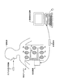
図1は、本発明の実施の形態1にかかる送受信システムの一構成例を模式的に示す模式図である。図1に示すように、この実施の形態1にかかる送受信システムは、被検体1の臓器内部に導入される送信装置の一例であるカプセル型内視鏡2と、被検体1内部のカプセル型内視鏡2によって無線送信された体内画像データを受信する受信装置3と、受信装置3によって受信された体内画像データをもとに被検体1の体内画像を表示する画像表示装置4と、かかる受信装置3と画像表示装置4との間におけるデータの受け渡しを行うための記録媒体5とを備える。
(Embodiment 1)
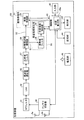
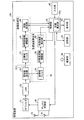
FIG. 1 is a schematic diagram schematically illustrating a configuration example of a transmission / reception system according to the first exemplary embodiment of the present invention. As shown in FIG. 1, the transmission / reception system according to the first embodiment includes a
カプセル型内視鏡2は、本発明にかかる送受信システムの送信装置の一例であり、体内画像を撮像し得る撮像機能と撮像した体内画像データを外部に無線送信する無線通信機能とを有する。具体的には、カプセル型内視鏡2は、被検体1に経口摂取され、その後、蠕動運動等によって被検体1の消化管内部を移動する。かかるカプセル型内視鏡2は、被検体1の体内画像を順次撮像し、その都度、得られた体内画像データを外部に無線送信する。この場合、カプセル型内視鏡2は、体内画像データを含む送信信号を生成し、この生成した送信信号をデジタル変調した変調信号を被検体1外部の受信装置3に無線送信する。カプセル型内視鏡2は、被検体1の内部に導入されてから外部に自然排出されるまでの期間、かかる体内画像の撮像動作と体内画像データの無線送信動作とを繰り返す。なお、かかるカプセル型内視鏡2の詳細な構成については、後述する。
The
受信装置3は、上述したカプセル型内視鏡2によって無線送信された変調信号を受信する受信装置の一例であり、カプセル型内視鏡2から受信した変調信号の受信電界強度を受信アンテナ毎に検出する受信強度検出系と、このカプセル型内視鏡2から受信した変調信号に含まれる体内画像データを信号処理する信号処理系とを備える。具体的には、受信装置3は、複数の受信アンテナ3a〜3hを有し、これらの受信アンテナ3a〜3hを介してカプセル型内視鏡2からの変調信号を受信する。受信装置3は、この受信した変調信号を受信強度検出系と信号処理系とに分岐し、この分岐した一方の変調信号の受信電界強度を受信強度検出系によって検出するとともに、他方の変調信号に含まれる体内画像データを信号処理系によって信号処理して被検体1の体内画像を取得する。かかる受信装置3には記録媒体5が着脱可能に挿着され、受信装置3は、挿着された記録媒体5に体内画像データ等の各種データを保存する。なお、かかる受信装置3の詳細な構成については、後述する。
The receiving device 3 is an example of a receiving device that receives the modulated signal wirelessly transmitted by the
受信アンテナ3a〜3hは、図1に示したように、被検体1の体表上の所定位置(例えば被検体1内部におけるカプセル型内視鏡2の移動経路上の位置)に分散配置される。受信アンテナ3a〜3hは、上述した受信装置3に接続され、図1に示した配置状態においてカプセル型内視鏡2からの変調信号を捕捉し、この捕捉した変調信号を受信装置3に送出する。なお、本発明にかかる受信装置3の受信アンテナは、被検体1に対して1以上望ましくは複数配置されればよく、その配置数量は特に8つに限定されない。
As shown in FIG. 1, the receiving
画像表示装置4は、カプセル型内視鏡2によって撮像された被検体1の体内画像等の各種データを表示する。具体的には、画像表示装置4は、上述した記録媒体5が着脱可能に挿着され、この挿着された記録媒体5を媒介にして体内画像データ等の各種データを取得し、この取得した各種データを表示するワークステーション等のような構成を有する。かかる画像表示装置4は、CRTディスプレイまたは液晶ディスプレイ等によって画像を表示してもよいし、プリンタ等のように他の媒体に画像を出力してもよい。なお、かかる画像表示装置4によって表示されるデータとして、例えば、被検体1の体内画像群、被検体1内部におけるカプセル型内視鏡2の位置、被検体1を特定する患者名や患者ID等の患者情報等が挙げられる。
The image display device 4 displays various data such as an in-vivo image of the subject 1 captured by the
記録媒体5は、上述した受信装置3および画像表示装置4に着脱可能に挿着可能な可搬型の記録媒体であり、両者に対する挿着時にデータの出力および記録が可能な構造を有する。具体的には、記録媒体5は、受信装置3に挿着された状態において、受信装置3がカプセル型内視鏡2から受信した体内画像データ等の各種データを記録する。一方、記録媒体5は、カプセル型内視鏡2が被検体1の外部に排出された後、受信装置3から取り出されて画像表示装置4に挿着される。この状態において、記録媒体5は、蓄積している各種データを画像表示装置4に出力する。これによって、かかる記録媒体5内の各種データは、画像表示装置4に取り込まれる。
The
つぎに、上述したカプセル型内視鏡2の構成について詳細に説明する。図2は、本発明の実施の形態1にかかる送信装置であるカプセル型内視鏡の一構成例を示すブロック図である。図2に示すように、この実施の形態1にかかるカプセル型内視鏡2は、被写体を照明する照明部21と、照明部21によって照明された被写体の画像を撮像する撮像部22と、撮像部22によって撮像された画像データを含む送信信号を生成する信号処理部23と、信号処理部23によって生成された送信信号をデジタル変調して無線送信する送信ユニット24と、カプセル型内視鏡2の各構成部を制御する制御部25と、カプセル型内視鏡2の各構成部の駆動電力を供給する電源部26とを備える。
Next, the configuration of the
照明部21は、LED等の発光素子を用いて実現され、制御部25の制御に基づいて照明光を発光して、被検体1の体内部位等の被写体を照明する。撮像部22は、CCDまたはCMOS等の固体撮像素子と集光レンズ等の光学系とを用いて実現され、制御部25の制御に基づいて被写体の画像を撮像する。具体的には、撮像部22は、照明部21によって照明された被検体1の臓器内部の画像(すなわち体内画像)を撮像する。かかる撮像部22によって撮像された被検体1の体内画像データは、この実施の形態1にかかる送受信システムの送信装置(カプセル型内視鏡2)と受信装置3との間で送受信される所定のデータの一例であり、信号処理部23に送信される。
The
信号処理部23は、カプセル型内視鏡2が受信装置3に無線送信する送信信号を生成する信号生成部として機能する。具体的には、信号処理部23は、制御部25の制御に基づいて動作し、撮像部22が被検体1の体内画像を撮像する都度、撮像部22から体内画像データを取得し、この取得した体内画像データを含む送信信号を生成する。この場合、信号処理部23は、図3に示す信号フォーマットに基づいて、1フレーム分の体内画像データを含む1フレームの送信信号S0を生成する。すなわち、信号処理部23は、送信信号S0の先頭の信号区間である信号検出区間A1に、信号検出のための検出用データD1を有する検出信号を含め、この信号検出区間A1に後続する信号区間である強度検出区間A2に、データ値を固定した一定デジタルデータD2を有する直流信号を含め、この強度検出区間A2に後続する信号区間であるアイドリング区間A3に、周波数調整用のデジタルデータD3を有する調整信号を含め、このアイドリング区間A3に後続する信号区間であるデータ区間A4に、撮像部22から取得した体内画像データD4を有する画像信号を含め、この結果、1フレームの送信信号S0を生成する。信号処理部23は、このように生成した送信信号S0を送信ユニット24に送出する。
The
ここで、信号検出区間A1内の検出用データD1は、高レベルのデジタル値(1)と低レベルのデジタル値(0)とによって形成されるデジタルデータであり、受信装置3が送信信号S0の始まり(具体的には送信信号S0をデジタル変調した変調信号の始まり)を検出するために用いられる。強度検出区間A2内の直流信号は、周波数を0[Hz]に固定した特定信号の一例であり、一定デジタルデータD2によって形成される。アイドリング区間A3内の調整信号は、デジタル値(1)とデジタル値(0)とを繰り返すデジタルデータD3によって形成され、強度検出区間A2の一定デジタルデータD2からデータ区間A4内の体内画像データD4にデータが移行する際に生じる周波数のずれを補正するために用いられる。 Here, the detection data D1 in the signal detection section A1 is digital data formed by a high-level digital value (1) and a low-level digital value (0), and the reception device 3 transmits the transmission signal S0. It is used to detect the beginning (specifically, the beginning of a modulation signal obtained by digitally modulating the transmission signal S0). The DC signal in the intensity detection section A2 is an example of a specific signal whose frequency is fixed to 0 [Hz], and is formed by constant digital data D2. The adjustment signal in the idling section A3 is formed by digital data D3 that repeats the digital value (1) and the digital value (0), and changes from the constant digital data D2 in the intensity detection section A2 to the in-vivo image data D4 in the data section A4. It is used to correct frequency shifts that occur when data is transferred.
なお、かかる強度検出区間A2内の直流信号は、図3に示すようにデジタル値(1)に固定した一定デジタルデータD2によって形成されてもよいし、デジタル値(0)に固定した一定デジタルデータD2によって形成されてもよい。 The DC signal in the intensity detection section A2 may be formed by the constant digital data D2 fixed to the digital value (1) as shown in FIG. 3, or the constant digital data fixed to the digital value (0). It may be formed by D2.
送信ユニット24は、信号処理部23によって生成された送信信号S0をデジタル変調して外部に無線送信するためのものである。具体的には、送信ユニット24は、信号処理部23によって生成された送信信号S0を周波数偏移変調(FSK変調)する変調部24aと、変調部24aによって変調された送信信号S0を外部に無線送信する送信部24bとを備える。なお、この実施の形態1では、FSK変調方式によって変調した変調信号を送信する送信ユニット24にしているが、本発明はFSK変調方式に限定されるものではなく、送信ユニット24の変調方式が他の変調方式(FSK変調方式以外)であっても本発明は実施可能である。
The transmission unit 24 is for digitally modulating the transmission signal S0 generated by the
変調部24aは、信号処理部23によって生成された送信信号S0をFSK変調して、一定デジタルデータD2をもつ直流信号に対応する狭帯域信号成分を強度検出区間A2に含む変調信号を生成する。具体的には、変調部24aは、搬送波周波数fcの信号(搬送波信号)を発信する信号発信部およびVCO等を用いて実現される。変調部24aは、制御部25の制御に基づいて、信号処理部23から送信信号S0を取得し、その都度、この取得した送信信号S0を搬送波信号に重畳してFSK変調処理を行う。この場合、変調部24aは、周波数を搬送波周波数にロックするPLL制御を行いつつ、送信信号S0をFSK変調した変調信号を生成する。変調部24aは、この生成した変調信号を送信部24bに送出する。
The
かかる変調部24aのFSK変調によって生成された変調信号は、検出用データD1に対応する広帯域信号成分を信号検出区間A1に含み、一定デジタルデータD2をもつ直流信号に対応する狭帯域信号成分を強度検出区間A2に含み、デジタルデータD3に対応する広帯域信号成分をアイドリング区間A3に含み、体内画像データD4に対応する広帯域信号成分をデータ区間A4に含む。ここで、強度検出区間A2の信号が一定デジタルデータD2からなる直流信号である場合、この直流信号の周波数は、変調部24aのPLL制御によって搬送波周波数に収束し、この結果、変調部24aは、狭帯域信号成分である搬送波信号(すなわち単一周波数の無変調信号)を強度検出区間A2に含めた変調信号を生成する。かかる変調信号の強度検出区間A2における周波数特性は、図4に示すように、搬送波周波数fcに周波数スペクトルをもつ狭帯域信号成分のものになる。なお、かかる狭帯域信号成分である搬送波信号の帯域幅は、例えば数10[kHz]程度である。
The modulation signal generated by the FSK modulation of the
一方、かかる変調信号の信号検出区間A1、アイドリング区間A3、およびデータ区間A4の各々に含まれる各広帯域信号成分は、図5に示すように、搬送波周波数fcを中心とする周波数偏差△fc(片側)の2倍の帯域幅と、デジタル値(0)に対応する周波数f0(=fc−△fc)を中心とする周波数偏差△fcの2倍の帯域幅と、デジタル値(1)に対応する周波数f1(=fc+△fc)を中心とする周波数偏差△fcの2倍の帯域幅とを加算した占有帯域幅をもつ周波数特性を有する。なお、かかる広帯域信号成分の占有帯域幅は、例えば数MHz以上である。 On the other hand, each wideband signal component included in each of the signal detection section A1, the idling section A3, and the data section A4 of the modulated signal has a frequency deviation Δfc (one side) centered on the carrier frequency fc as shown in FIG. ) Corresponding to the digital value (1) and a bandwidth twice the frequency deviation Δfc centered on the frequency f0 (= fc−Δfc) corresponding to the digital value (0). It has a frequency characteristic having an occupied bandwidth obtained by adding a bandwidth twice as large as the frequency deviation Δfc centered on the frequency f1 (= fc + Δfc). Note that the occupied bandwidth of such a broadband signal component is, for example, several MHz or more.
送信部24bは、上述した変調部24aによって生成された変調信号を外部に無線送信する。具体的には、送信部24bは、制御部25の制御に基づいて、変調部24aから変調信号を取得し、その都度、この取得した変調信号を高周波化して無線送信する。かかる送信部24bは、送信アンテナ24cを有し、この高周波化した変調信号を送信アンテナ24cを介して外部の受信装置3(図1参照)に無線送信する。
The
制御部25は、処理プログラムを実行するCPUと、処理プログラム等が予め記録されたROMと、各処理の演算パラメータ等を記憶するRAMとを用いて実現され、カプセル型内視鏡2の各構成部を制御する。具体的には、制御部25は、上述した照明部21、撮像部22、信号処理部23、変調部24a、送信部24bの各動作を制御し、且つ、撮像部22、信号処理部23、変調部24a、送信部24bの各間における信号の入出力を制御する。
The
電源部26は、所定の電力を有する電池とオンオフ状態を切り替えるスイッチ部とを用いて実現され、オン状態においてカプセル型内視鏡2の各構成部(照明部21、撮像部22、信号処理部23、変調部24a、送信部24b、および制御部25)に駆動電力を供給する。なお、電源部26は、オフ状態において各構成部への駆動電力の供給を停止する。
The
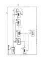
つぎに、上述した受信装置3の構成について詳細に説明する。図6は、本発明の実施の形態1にかかる受信装置の一構成例を示すブロック図である。図6に示すように、この実施の形態1にかかる受信装置3は、上述した受信アンテナ3a〜3hと、受信アンテナ3a〜3hを択一的に切り替えるアンテナ切替部30と、RFフィルタ31と、低雑音増幅部(LNA)32とを備える。また、受信装置3は、受信信号を分岐する周波数混合器33と、受信アンテナ毎に受信電界強度を検出する受信強度検出系40と、受信信号に含まれる体内画像データを信号処理する画像処理系41とを備える。また、受信装置3は、入力部42と、表示部43と、記憶部44と、制御部45と、電源部46とを備える。
Next, the configuration of the receiving device 3 described above will be described in detail. FIG. 6 is a block diagram of a configuration example of the receiving apparatus according to the first embodiment of the present invention. As shown in FIG. 6, the receiving apparatus 3 according to the first embodiment includes the above-described
アンテナ切替部30は、カプセル型内視鏡2が無線送信した変調信号を受信する際の受信アンテナを複数の受信アンテナ3a〜3hの中から択一的に選択するためのものである。具体的には、アンテナ切替部30は、複数の受信アンテナ3a〜3h(図1参照)がケーブルを介して接続され、制御部45の制御に基づいて複数の受信アンテナ3a〜3hのうちのいずれかを選択し、この選択した受信アンテナ(すなわち受信アンテナ3a〜3hのいずれか)とRFフィルタ31とを接続する。かかるアンテナ切替部30は、制御部45の制御に基づいて、このRFフィルタ31と電気的に接続する受信アンテナを受信アンテナ3a〜3hの中から順次切り替える。かかる受信アンテナ3a〜3hのいずれかを介してアンテナ切替部30に受信されたカプセル型内視鏡2からの変調信号は、RFフィルタ31に送出される。
The
RFフィルタ31は、カプセル型内視鏡2からの変調信号に含まれる広帯域信号成分を通過可能な通過帯域幅(例えば数MHz以上の帯域幅)を有する帯域通過フィルタである。RFフィルタ31は、カプセル型内視鏡2からの変調信号をアンテナ切替部30から取得し、この通過帯域幅の範囲内の信号、すなわち、このカプセル型内視鏡2からの変調信号を通過させる。かかるRFフィルタ31を通過した変調信号は、LNA32に送出される。LNA32は、カプセル型内視鏡2からの変調信号をRFフィルタ31から取得し、このRFフィルタ31を通過した変調信号を増幅する。かかるLNA32によって増幅された変調信号は、周波数混合器33に送出される。
The
周波数混合器33は、受信アンテナ3a〜3hのいずれかを介して受信したカプセル型内視鏡2からの変調信号に異なる周波数の信号を混合して、この変調信号の周波数を中間周波数に変換(ダウンコンバート)する周波数変換機能と、この中間周波数の変調信号を受信強度検出系40と画像処理系41とに分岐する信号分岐機能とを有する。具体的には、周波数混合器33は、LNA32によって増幅されたカプセル型内視鏡2からの変調信号を取得し、この取得した変調信号に異なる周波数の信号を混合することによって、この変調信号の高周波周波数を中間周波数にダウンコンバートする。そして、周波数混合器33は、このダウンコンバートした変調信号(すなわち中間周波数の変調信号)を受信強度検出系40と画像処理系41とに分岐して出力する。かかる周波数混合器33によって分岐された一方の変調信号S1は、受信強度検出系40に送出され、他方の変調信号S2は、画像処理系41に送出される。
The
受信強度検出系40は、受信アンテナ3a〜3hを介して受信したカプセル型内視鏡2からの変調信号の電波強度すなわち受信電界強度を受信アンテナ毎に検出する。かかる受信強度検出系40は、狭帯域フィルタ34と、中間周波数増幅器35と、受信強度検出部36とを備える。
The reception
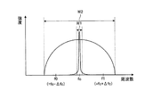
狭帯域フィルタ34は、受信アンテナ3a〜3hを介して受信したカプセル型内視鏡2からの変調信号に含まれる狭帯域信号成分を抽出するための帯域通過フィルタである。具体的には、狭帯域フィルタ34は、図7に示すように、強度検出区間A2内の狭帯域信号成分(すなわち搬送波信号)に比して広帯域であり且つ変調信号S1の占有帯域幅(すなわち変調信号S1に含まれる広帯域信号成分)に比して狭帯域である通過帯域幅W1を有する。狭帯域フィルタ34は、周波数混合器33によって分岐された変調信号S1を取得し、この取得した変調信号S1の狭帯域信号成分を抽出する。かかる狭帯域フィルタ34によって抽出された変調信号S1の狭帯域信号成分は、中間周波数増幅器35に送出される。中間周波数増幅器35は、狭帯域フィルタ34によって抽出された変調信号S1の狭帯域信号成分を増幅し、この増幅した変調信号S1の狭帯域信号成分を受信強度検出部36に送出する。なお、かかる狭帯域フィルタ34の通過帯域幅W1は、後述する広帯域フィルタ37の通過帯域幅W2(例えば数MHz〜10MHz程度)の1/10000以上、且つ1/10以下であり、具体的には数kHz〜100kHz程度である。
The
受信強度検出部36は、受信アンテナ3a〜3hを介して受信したカプセル型内視鏡2からの変調信号の受信電界強度を受信アンテナ毎に検出する。具体的には、受信強度検出部36は、中間周波数増幅器35によって増幅された変調信号S1の狭帯域信号成分を取得し、この取得した狭帯域信号成分、すなわち変調信号S1の強度検出区間A2に含まれる搬送波信号の受信電界強度を検出する。受信強度検出部36は、この検出した受信電界強度を示すアナログ信号、例えばRSSI(Received Signal Strength Indicator)信号をデジタル信号に変換し、得られたRSSIのデジタル信号を受信電界強度の検出結果として制御部45に送出する。かかる受信強度検出部36は、複数の受信アンテナ3a〜3hの中からカプセル型内視鏡2からの変調信号を受信する受信アンテナがアンテナ切替部30によって切り替えられる都度、中間周波数増幅器35から取得した変調信号S1の狭帯域信号成分(搬送波信号)の受信電界強度を検出し、受信アンテナ毎に受信電界強度の検出結果を制御部45に送出する。
The reception
画像処理系41は、受信アンテナ3a〜3hを介して受信したカプセル型内視鏡2からの変調信号に含まれる所定のデータを信号処理する信号処理系として機能し、かかる所定のデータの一例である画像データ(具体的にはカプセル型内視鏡2によって撮像された体内画像データ)を信号処理する。かかる画像処理系41は、広帯域フィルタ37と、中間周波数増幅器38と、画像処理部39とを備える。
The
広帯域フィルタ37は、受信アンテナ3a〜3hを介して受信したカプセル型内視鏡2からの変調信号に含まれる広帯域信号成分を抽出するための帯域通過フィルタである。具体的には、広帯域フィルタ37は、図7に示すように、変調信号S2の占有帯域幅に比して広帯域な通過帯域幅W2を有する。広帯域フィルタ37は、周波数混合器33によって分岐された変調信号S2を取得し、この取得した変調信号S2に含まれる広帯域信号成分および狭帯域信号成分、すなわち通過帯域幅W2の範囲内の信号成分を抽出する。なお、かかる広帯域フィルタ37によって抽出される信号成分として、信号検出区間A1内の検出用データD1に対応する広帯域信号成分と、強度検出区間A2内の狭帯域信号成分と、アイドリング区間A3内のデジタルデータD3に対応する広帯域信号成分と、データ区間A4内の体内画像データD4に対応する広帯域信号成分が挙げられる。かかる広帯域フィルタ37によって抽出された変調信号S2の信号成分は、中間周波数増幅器38に送出される。中間周波数増幅器38は、狭帯域フィルタ37によって抽出された変調信号S2の信号成分を増幅し、この増幅した変調信号S2の信号成分を画像処理部39に送出する。
The
画像処理部39は、受信アンテナ3a〜3hを介して受信したカプセル型内視鏡2からの変調信号に含まれる体内画像データを信号処理して、この体内画像データに対応する被検体1の体内画像を生成する。具体的には、画像処理部39は、中間周波数増幅器38によって増幅された変調信号S2を取得し、この取得した変調信号S2に対して所定の復調処理等を行って、この変調信号S2から画像信号を復調する。画像処理部39は、この画像信号に含まれる体内画像データD4を抽出し、得られた体内画像データD4を信号処理して被検体1の体内画像を生成する。かかる画像処理部39は、複数の受信アンテナ3a〜3hの中からカプセル型内視鏡2からの変調信号を受信する受信アンテナがアンテナ切替部30によって切り替えられる都度、中間周波数増幅器38から取得した変調信号S2から画像信号を復調して体内画像データD4を取得し、この体内画像データD4に対応する体内画像を生成する。かかる画像処理部39によって生成された体内画像は、制御部45に順次送出される。
The
入力部42は、入力キー等を用いて実現され、制御部45に対して指示する指示情報等の各種情報を入力する。かかる入力部42によって制御部45に入力される情報として、例えば、カプセル型内視鏡2からの変調信号の受信開始を指示する指示情報、受信終了を指示する指示情報、表示出力を指示する指示情報、被検体1の患者名や患者ID等の患者情報、検査日(被検体1内にカプセル型内視鏡2を導入する日)等の各種情報が挙げられる。
The
表示部43は、LEDまたは液晶ディスプレイ等を用いて実現され、制御部45の制御に基づいて各種情報を表示する。かかる表示部43に表示される情報として、例えば、受信装置3の動作状態(受信実行中または受信待機中等)、被検体1の体内画像、被検体1の患者情報、検査日等の各種情報が挙げられる。
The
記憶部44は、上述した記録媒体5(図1参照)を着脱可能に挿着でき、制御部45の制御に基づいて各種データを記録媒体5内に保存する。かかる記憶部44によって記録媒体5内に保存(蓄積)されるデータとして、例えば、被検体1の体内画像、被検体1内部におけるカプセル型内視鏡2の位置データ等が挙げられる。
The
なお、記憶部44は、RAMまたはフラッシュメモリ等のメモリICあるいはハードディスクを備えることによって記憶部44自体が被検体1の体内画像等の各種データを記憶するように構成されてもよい。この場合、受信装置3は、上述した画像表示装置4(図1参照)に対して有線通信または無線通信を行って、かかる記憶部44内の各種データを画像表示装置4に送信してもよい。
The
制御部45は、処理プログラムを実行するCPUと、処理プログラム等が予め記録されたROMと、各処理の演算パラメータまたは入力部42による入力情報等を記憶するRAMとを用いて実現され、受信装置3の各構成部を制御し、且つ各構成部間における信号の入出力を制御する。具体的には、制御部45は、入力部42によって入力された指示情報に基づいてアンテナ切替部30を制御し、カプセル型内視鏡2からの変調信号の受信開始または受信終了を制御する。また、制御部45は、入力部42によって入力された指示情報に基づいて表示部43等を制御し、被検体1の体内画像および患者情報等を表示部43に表示させる。この場合、制御部45は、記憶部44から読み出した体内画像を表示部43に表示させてもよい。一方、制御部45は、カプセル型内視鏡2からの変調信号を受信(捕捉)する受信アンテナを複数の受信アンテナ3a〜3hの中から順次切り替えるようにアンテナ切替部30を制御し、上述した受信強度検出部36および画像処理部39の動作開始タイミングを制御する。この場合、制御部45は、アンテナ切替部30に受信アンテナを切り替えさせるタイミングと受信強度検出部36および画像処理部39の各動作開始タイミングとを同期させてもよい。
The
また、制御部45は、被検体1内部におけるカプセル型内視鏡2の位置を算出する位置算出部45aを有する。位置算出部45aは、受信強度検出部36によって受信アンテナ毎に検出された受信電界強度、すなわち受信アンテナ3a〜3hの各受信電界強度を取得し、この取得した各受信電界強度をもとに被検体1内におけるカプセル型内視鏡2の位置データを算出する。具体的には、位置算出部45aは、予め設定された受信アンテナ3a〜3hの各位置座標データを有し、1フレームの変調信号毎に取得した受信アンテナ3a〜3hの各受信電界強度の中から強度が高い順に上位3つの受信電界強度を選択する。位置算出部45aは、かかる上位3つの受信電界強度と、これら3つの受信電界強度に対応する3つの受信アンテナ(受信アンテナ3a〜3hのうちの3つの受信アンテナ)の各位置座標データとを用い、三点交差法等に基づいて被検体1内部におけるカプセル型内視鏡2の位置データを算出する。
The
なお、かかる位置算出部45aによって算出されたカプセル型内視鏡2の位置データは、画像処理部39によって生成された体内画像と対応付けられた状態で記憶部44(具体的には記録媒体5)に保存される。この場合、制御部45は、この上位3つの受信電界強度のいずれか一つ(望ましくは最上位の受信電界強度)に対応する変調信号S2内の体内画像データD4に基づく被検体1の体内画像とカプセル型内視鏡2の位置データとを対応付け、かかる被検体1の体内画像とカプセル型内視鏡2の位置データとを記録媒体5に保存する。
Note that the position data of the
電源部46は、所定の電力を有する電池とオンオフ状態を切り替えるスイッチ部とを用いて実現され、オン状態において受信装置3の各構成部に必要な駆動電力を供給する。また、電源部46は、オフ状態において各構成部への駆動電力の供給を停止する。
The
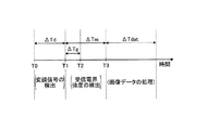
つぎに、本発明の実施の形態1にかかる受信装置3の受信強度検出部36および画像処理部39の各動作について説明する。図8は、実施の形態1にかかる受信装置の動作タイミングの一例を示す模式図である。以下では、図8を参照しつつ、上述した1フレームの送信信号S0をデジタル変調した1フレームの変調信号について受信電界強度の検出および体内画像データの信号処理を実行する際の受信装置3の動作を説明する。
Next, operations of the reception
受信装置3は、アンテナ切替部30によって受信アンテナ3a〜3hの中から選択された受信アンテナを介してカプセル型内視鏡2からの変調信号を受信し、この受信した変調信号を周波数混合器33によって2つの変調信号S1,S2に分岐する。この場合、制御部45は、アンテナ切替部30に受信アンテナを選択させたタイミング(時間T0)において受信強度検出部36および画像処理部39の各動作を開始させる。
The receiving device 3 receives the modulation signal from the
画像処理部39は、かかる制御部45の制御に基づいて動作を開始し、この時間T0から信号検出期間△Tdが経過するまでにカプセル型内視鏡2から1フレームの変調信号が無線送信されている旨を検出する。画像処理部39は、広帯域フィルタ37を通過した変調信号S2の信号検出区間A1内の広帯域信号成分を取得し、この取得した広帯域信号成分に含まれる検出用データD1をもとに、この変調信号S2の始まりを検出する。
The
なお、信号検出期間△Tdは、1フレームの変調信号の始まりを検出するために画像処理部39に予め設定された期間であり、画像処理部39が検出用データD1をもとに変調信号の始まりを検出するに充分な期間である。
The signal detection period ΔTd is a period set in advance in the
つぎに、受信強度検出部36は、上述した信号検出期間△Tdが経過したタイミング(時間T1)から強度検出期間△Tmが経過するまでに、この変調信号S1の受信電界強度、すなわち受信アンテナ毎の受信電界強度を検出する。具体的には、受信強度検出部36は、この時間T1からガード期間△Tgが経過するまでの期間、受信電界強度の検出処理の開始を待機し、このガード期間△Tgが経過したタイミング(時間T2)において受信電界強度の検出処理を開始する。かかる受信強度検出部36は、この強度検出期間△Tm内に、この変調信号S1の強度検出区間A2に含まれる狭帯域信号成分、すなわち搬送波信号を抽出し、この抽出した搬送波信号の受信電界強度を検出し終える。かかる受信強度検出部36によって検出された搬送波信号の受信電界強度は、受信アンテナ毎の受信電界強度の検出結果として制御部45に送出される。
Next, the reception
ここで、ガード期間△Tgは、強度検出区間A2内の狭帯域信号成分の周波数を一定の周波数(具体的には搬送波周波数)に安定化するために受信強度検出部36に予め設定された期間であり、1フレームの変調信号において信号検出区間A1から強度検出区間A2に信号成分が移行する際に生じる周波数の不安定な状態を解消するに充分な期間である。受信強度検出部36は、強度検出期間△Tmにおいてガード期間△Tgだけ受信電界強度の検出処理の開始を待機することによって、強度検出区間A2内の狭帯域信号成分の周波数を搬送波周波数fcに安定化することができ、この結果、レベル変動が少ない安定した信号レベル(すなわち略一定の信号レベル)の狭帯域信号成分を取得できる。受信強度検出部36は、かかる安定した信号レベルをもつ狭帯域信号成分の受信電界強度を検出することによって、受信アンテナ毎の受信電界強度を高精度に検出することができる。
Here, the guard period ΔTg is a period set in advance in the reception
なお、強度検出期間△Tmは、受信強度検出部36が1フレームの変調信号の受信電界強度を検出するに充分な期間であり、受信強度検出部36および画像処理部39に予め設定される。かかる強度検出期間△Tmは、上述した信号検出期間△Tdとガード期間△Tgと強度測定期間△Tmeans(受信強度検出部36による受信電界強度の検出処理に必要な処理時間)との加算値以上であることが望ましい。何故ならば、このように強度検出期間△Tmを設定することによって、受信強度検出部36は、強度検出期間△Tm内であってガード期間△Tgが経過した後に、変調信号S2の強度検出区間A2に含まれる狭帯域信号成分の受信電界強度を確実に検出できるようになるからである。
The intensity detection period ΔTm is a period sufficient for the reception
一方、画像処理部39は、上述した信号検出期間△Tdが経過したタイミング(時間T1)から強度検出期間△Tmが経過し、さらに、この強度検出期間△Tmの経過タイミング(時間T3)からアイドリング期間△Tiが経過するまで、上述した変調信号S2を取得しつつ体内画像データに対する信号処理の開始を待機する。この場合、かかる画像処理部39に入力される変調信号S2の信号成分は、強度検出区間A2内の狭帯域信号成分からアイドリング区間A3内の広帯域信号成分に移行する。
On the other hand, the
ここで、アイドリング期間△Tiは、1フレームの変調信号において強度検出区間A2内の狭帯域信号成分からデータ区間A4内の広帯域信号成分に信号成分が移行する際に生じる周波数のずれを補正(解消)するに充分な期間であり、受信強度検出部36および画像処理部39に予め設定される。画像処理部39は、変調信号S2の強度検出区間A2内の狭帯域信号成分を取得し終えたタイミング、すなわち図8に示す時間T3からアイドリング期間△Tiだけ信号処理の開始を待機し、これによって、変調信号S2の広帯域信号成分の中心周波数を搬送波周波数に収束させるとともに周波数偏移△fcを安定化する。かかるアイドリング期間△Tiを経て画像処理部39に入力される変調信号S2の広帯域信号成分は、搬送波周波数fcを中心に等間隔に周波数を偏移させる状態、すなわち体内画像データD4を含む広帯域信号成分として好適な状態になる。なお、かかるアイドリング期間△Tiは、上述したガード期間△Tg以上の期間に設定することが望ましい。これによって、上述した変調信号S2の広帯域信号成分は、アイドリング期間△Ti内に確実に好適な状態になる。
Here, the idling period ΔTi corrects (cancels) a frequency shift that occurs when the signal component shifts from the narrowband signal component in the intensity detection section A2 to the wideband signal component in the data section A4 in the modulation signal of one frame. ) And is set in advance in the
つぎに、画像処理部39は、上述したアイドリング期間△Tiが経過したタイミング(時間T4)からデータ処理期間△Tdatが経過するまでに、この変調信号S2のデータ区間A4に含まれる体内画像データD4を信号処理する。すなわち、画像処理部39は、データ処理期間△Tdat内に1フレーム分の体内画像データD4を取得し、この取得した体内画像データD4に基づいた1フレームの体内画像を生成する。画像処理部39は、この生成した1フレームの体内画像、すなわち被検体1の体内画像を制御部45に送出する。
Next, the
その後、画像処理部39は、制御部45によって動作開始を指示されるまで待機状態になる。なお、受信強度検出部36は、上述したアイドリング期間△Tiおよびデータ処理期間△Tdatにおいて、変調信号S1を取得しつつ受信電界強度の検出処理の開始を待機し、制御部45によって動作開始を指示されるまで、この待機状態を継続する。かかる受信強度検出部36および画像処理部39は、制御部45によって動作開始を指示される都度、図8に示した動作タイミングに沿って上述した動作を繰り返し実行する。この結果、受信強度検出部36は、各受信アンテナの受信電界強度を順次検出し、画像処理部39は、1フレームの体内画像を順次生成する。
Thereafter, the
ここで、受信強度検出部36によって受信電界強度が検出される変調信号S1の強度検出区間A2には、略一定の信号レベルを有する狭帯域信号成分である搬送波信号が無変調の状態で組み込まれている。このため、かかる強度検出区間A2の狭帯域信号成分を抽出する狭帯域フィルタ34の通過帯域幅W1は、上述した広帯域フィルタ37の通過帯域フィルタW2(すなわち体内画像データD4等を含む広帯域信号成分を抽出する帯域通過フィルタの通過帯域幅)に比して極めて狭帯域に設定できる。これによって、受信強度検出部35に入力されるノイズを低減でき且つ狭帯域信号成分のSN比を大きくすることができ、この結果、受信強度検出部36は、検出可能な受信電界強度の下限値をより低くできるとともに受信電界強度のダイナミックレンジを大きくすることができる。かかる受信強度検出部36は、体内画像データD4を含むカプセル型内視鏡2からの変調信号を受信した際の受信電界強度を受信アンテナ毎に安定して検出できる。
Here, a carrier wave signal, which is a narrowband signal component having a substantially constant signal level, is incorporated in an unmodulated state in the intensity detection section A2 of the modulated signal S1 in which the received electric field intensity is detected by the received
かかる受信強度検出部36によって検出される受信アンテナ毎の受信電界強度は、カプセル型内視鏡2の位置検出等の所定のアプリケーションに有用である。具体的には、位置算出部45aは、上述したように、受信強度検出部36によって検出された各受信アンテナ3a〜3hの受信電界強度を取得し、この取得した各受信電界強度のうちの上位所定数(例えば3つ)の受信電界強度を用いて被検体1内部におけるカプセル型内視鏡2の位置データを算出(検出)する。この場合、位置算出部45aは、これら各受信アンテナ3a〜3hの受信電界強度を互いに比較処理し、この比較処理結果に基づいて上位所定数の受信電界強度を選択する必要がある。
The reception field strength for each reception antenna detected by the reception
しかしながら、広帯域フィルタによって抽出された広帯域信号成分の受信電界強度を検出する従来技術では、この広帯域フィルタの通過帯域幅に応じて受信電界強度の検出下限値が上昇するため、受信電界強度を検出する際のノイズが増大し、これによって、受信電界強度がノイズに埋もれた状態、すなわち各受信電界強度の検出値(電圧値)が各受信アンテナ間において略同レベルの状態になってしまい、この結果、各受信アンテナの受信電界強度の大小を比較することが困難になる。 However, in the conventional technique for detecting the received electric field strength of the broadband signal component extracted by the wideband filter, the detection lower limit value of the received electric field strength increases according to the passband width of the wideband filter. As a result, the received electric field strength is buried in the noise, that is, the detection value (voltage value) of each received electric field strength is substantially the same level between the respective receiving antennas. It becomes difficult to compare the magnitudes of the received electric field strengths of the respective receiving antennas.
例えば、被検体1内部のカプセル型内視鏡2が被検体1の体表上の受信アンテナ3a〜3h(図1参照)のうちの受信アンテナ3dの近傍に位置する場合、この受信アンテナ3dの受信電界強度は、残りの受信アンテナ3a〜3c,3e〜3hに比して十分大きくなる。このため、位置算出部45aは、この受信アンテナ3dの受信電界強度を上位の強度として選択できる。しかし、残りの受信アンテナ3a〜3c,3e〜3hの受信電界強度は、受信電界強度の検出下限値に比して小さい場合、ノイズに埋もれて略同レベルの状態になってしまう。これによって、位置算出部45aは、これら残りの受信アンテナ3a〜3c,3e〜3hの受信電界強度の大小を正確に比較することが困難になり、この結果、被検体1内部におけるカプセル型内視鏡2の位置データを高精度に算出することが困難になる。
For example, when the
これに対して、本発明にかかる送受信システムでは、カプセル型内視鏡2と受信装置3との無線通信によって送受信される変調信号の強度検出区間A2に、略一定の信号レベルを有する狭帯域信号成分(搬送波信号)を組み込み、この強度検出区間A2から抽出した狭帯域信号成分の受信電界強度を検出しているので、この狭帯域信号成分に応じた狭帯域の通過帯域幅を帯域通過フィルタ(上述した狭帯域フィルタ34)に設定でき、これによって、受信強度検出部36の検出下限値を下げるとともに受信電界強度のダイナミックレンジを大きくすることができる。この結果、位置算出部45aは、たとえ微弱な受信電界強度であっても、受信アンテナ3a〜3h間における受信電界強度の差を確実に検出できるようになり、受信アンテナ3a〜3hの受信電界強度の中から上位所定数の受信電界強度を正確に選択することができる。かかる位置算出部45aは、上位所定数の受信電界強度を用いて被検体1内部におけるカプセル型内視鏡2の位置データを高精度に算出することができる。
On the other hand, in the transmission / reception system according to the present invention, a narrowband signal having a substantially constant signal level in the intensity detection section A2 of the modulation signal transmitted / received by wireless communication between the
以上、説明したように、本発明の実施の形態1では、カプセル型内視鏡等の送信装置が、狭帯域信号成分である搬送波信号のみを含む強度検出区間と体内画像データ等の所定のデータを含むデータ区間とを有する変調信号を無線送信し、この送信装置からの変調信号を複数の受信アンテナを介して受信する受信装置が、この送信装置から受信した変調信号を受信強度検出系と信号処理系とに分岐し、この分岐した一方の変調信号の強度検出区間に含まれる狭帯域信号成分を受信強度検出系の狭帯域フィルタによって抽出し、この狭帯域信号成分の受信電界強度を受信強度検出系によって検出し、他方の変調信号のデータ区間に含まれる所定のデータを信号処理系によって信号処理するように構成した。このため、この受信強度検出系の狭帯域フィルタの通過帯域幅を強度検出区間の狭帯域信号成分に応じて狭帯域化でき、これによって、受信強度検出系に入力されるノイズを低減できるとともに略一定の信号レベルを有する狭帯域信号成分の受信電界強度を検出できる。この結果、受信強度検出系の検出下限値を受信アンテナ毎の受信電界強度に比して低くできるとともに受信電界強度のダイナミックレンジをより大きくすることができ、所定のデータを含む送信装置からの変調信号を受信した際の受信電界強度を受信アンテナ毎に安定して検出できる送受信システムを実現できる。 As described above, in the first embodiment of the present invention, the transmission device such as the capsule endoscope has the intensity detection section including only the carrier wave signal that is a narrowband signal component and predetermined data such as in-vivo image data. A receiving device that wirelessly transmits a modulated signal having a data section including the received signal and receives the modulated signal from the transmitting device via a plurality of receiving antennas. Branches to the processing system, and the narrowband signal component included in the intensity detection section of one of the branched modulated signals is extracted by the narrowband filter of the reception intensity detection system, and the received electric field strength of this narrowband signal component is received intensity. The detection data is detected by the detection system, and the predetermined data included in the data section of the other modulation signal is processed by the signal processing system. For this reason, the pass band width of the narrow band filter of the reception intensity detection system can be narrowed according to the narrow band signal component of the intensity detection section, thereby reducing the noise input to the reception intensity detection system and substantially omitting it. The received electric field strength of the narrowband signal component having a constant signal level can be detected. As a result, the detection lower limit value of the reception intensity detection system can be lowered as compared with the reception electric field intensity for each reception antenna, and the dynamic range of the reception electric field intensity can be increased, and modulation from a transmission device including predetermined data can be performed. It is possible to realize a transmission / reception system that can stably detect the reception electric field strength when receiving a signal for each reception antenna.
(実施の形態2)
つぎに、本発明の実施の形態2について説明する。上述した実施の形態1では、カプセル型内視鏡2からの変調信号を周波数混合器33によって分岐していたが、この実施の形態2では、カプセル型内視鏡2からの変調信号を中間周波数増幅器によって分岐している。
(Embodiment 2)
Next, a second embodiment of the present invention will be described. In the first embodiment described above, the modulation signal from the
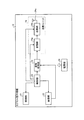
図9は、本発明の実施の形態2にかかる送受信システムの受信装置の一構成例を示すブロック図である。図9に示すように、この実施の形態2にかかる送受信システムの受信装置53は、上述した実施の形態1にかかる受信装置3の周波数混合器33に代えて周波数混合器52を備え、中間周波数増幅器38に代えて中間周波数増幅器58を備える。また、受信装置53は、上述した受信強度検出系40の中間周波数増幅器35を備えていない。かかる受信装置53において、狭帯域フィルタ34と受信強度検出部36とが接続され、この狭帯域フィルタ34によって抽出された狭帯域信号成分が受信強度検出部36に入力されるように構成される。また、かかる受信装置53において、受信強度検出系50は狭帯域フィルタ34と受信強度検出部36とによって構成され、画像処理系51は画像処理部39によって構成される。なお、この実施の形態2にかかる送受信システムは、上述した実施の形態1にかかる送受信システム(図1参照)の受信装置3に代えて受信装置53を備える。その他の構成は実施の形態1と同じであり、同一構成部分には同一符号を付している。
FIG. 9 is a block diagram of a configuration example of the receiving device of the transmission / reception system according to the second embodiment of the present invention. As illustrated in FIG. 9, the receiving
周波数混合器52は、カプセル型内視鏡2からの変調信号を分岐せずに広帯域フィルタ37に送出すること以外、上述した実施の形態1にかかる受信装置3の周波数混合器33と同様の機能を有する。すなわち、周波数混合器52は、LNA32から取得したカプセル型内視鏡2からの変調信号に異なる周波数の信号を混合して、この変調信号の高周波周波数を中間周波数にダウンコンバートし、このダウンコンバートした変調信号を分岐せずに広帯域フィルタ37に送出する。
The
中間周波数増幅器58は、増幅した中間周波数の変調信号を受信強度検出系50と画像処理系51とに分岐して出力すること以外、上述した実施の形態1にかかる受信装置3の中間周波数増幅器38と同様の機能を有する。すなわち、中間周波数増幅器58は、周波数混合器52によって中間周波数にダウンコンバートされた後に広帯域フィルタ37を通過したカプセル型内視鏡2からの変調信号の信号成分を増幅し、この増幅した変調信号を受信強度検出系50と画像処理系51とに分岐して出力する。かかる中間周波数増幅器58によって分岐された一方の変調信号S1は、受信強度検出系50の狭帯域フィルタ34に送出され、他方の変調信号S2は、画像処理系51の画像処理部39に送出される。
The
以上、説明したように、本発明の実施の形態2では、周波数混合器によって中間周波数にダウンコンバートした送信装置からの変調信号を増幅する中間周波数増幅器が、この増幅した変調信号を受信強度検出系と信号処理系とに分岐して出力するようにし、その他を実施の形態1と同様に構成した。このため、上述した実施の形態1と同様の作用効果を享受するとともに、受信装置内の受信強度検出系および信号処理系の各部品点数を少なくすることができ、この結果、送受信システムの受信装置を簡易な構成で実現することができる。
As described above, in the second embodiment of the present invention, the intermediate frequency amplifier that amplifies the modulation signal from the transmission device down-converted to the intermediate frequency by the frequency mixer is used for the reception intensity detection system. And the signal processing system are branched and output, and the others are configured in the same manner as in the first embodiment. For this reason, while enjoying the same effect as
(実施の形態3)
つぎに、本発明の実施の形態3について説明する。上述した実施の形態1では、カプセル型内視鏡2からの変調信号を周波数混合器33によって分岐していたが、この実施の形態3では、カプセル型内視鏡2からの変調信号を低雑音増幅部(LNA)によって分岐し、この分岐した変調信号を各々取得する受信強度検出系および画像処理系に、変調信号の高周波周波数を中間周波数にダウンコンバートする周波数混合器を各々設けている。
(Embodiment 3)
Next, a third embodiment of the present invention will be described. In
図10は、本発明の実施の形態3にかかる送受信システムの受信装置の一構成例を示すブロック図である。図10に示すように、この実施の形態3にかかる送受信システムの受信装置63は、上述した実施の形態1にかかる受信装置3のLNA32に代えてLNA62を備え、周波数混合器33に代えて周波数混合器67を備え、さらに受信強度検出系の周波数混合器66を備える。かかる受信装置63において、受信強度検出系60は、周波数混合器66と狭帯域フィルタ34と中間周波数増幅器35と受信強度検出部36とによって構成され、画像処理系61は、周波数混合器67と広帯域フィルタ37と中間周波数増幅器38と画像処理部39とによって構成される。また、LNA62は、受信強度検出系60の周波数混合器66と画像処理系61の周波数混合器67とに接続される。なお、この実施の形態3にかかる送受信システムは、上述した実施の形態1にかかる送受信システム(図1参照)の受信装置3に代えて受信装置63を備える。その他の構成は実施の形態1と同じであり、同一構成部分には同一符号を付している。
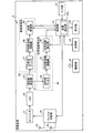
FIG. 10 is a block diagram of a configuration example of the receiving device of the transmission / reception system according to the third embodiment of the present invention. As illustrated in FIG. 10, the receiving
LNA62は、増幅したカプセル型内視鏡2からの変調信号を受信強度検出系60と画像処理系61とに分岐して出力すること以外、上述した実施の形態1にかかる受信装置3のLNA32と同様の機能を有する。すなわち、LNA62は、RFフィルタ31を通過したカプセル型内視鏡2からの変調信号を増幅し、この増幅した変調信号を受信強度検出系60と画像処理系61とに分岐して出力する。かかるLNA62によって分岐された一方の変調信号S1は、受信強度検出系60の周波数混合器66に送出され、他方の変調信号S2は、画像処理系61の周波数混合器67に送出される。
The
周波数混合器66は、上述したように受信強度検出系60の周波数混合器であり、LNA62によって分岐された変調信号S1を取得し、この取得した変調信号S1に異なる周波数の信号を混合して、この変調信号S1の高周波周波数を中間周波数にダウンコンバートする。ここで、かかる周波数混合器66によって変換される変調信号S1の中間周波数は、受信強度検出系60において処理し易い周波数であり、例えば受信強度検出部36による受信電界強度の検出処理に好適な周波数である。周波数混合器66は、このようにダウンコンバートした変調信号S1を分岐せずに狭帯域フィルタ34に送出する。
The
周波数混合器67は、上述したように画像処理系61の周波数混合器であり、LNA62によって分岐された変調信号S2を取得し、この取得した変調信号S2に異なる周波数の信号を混合して、この変調信号S2の高周波周波数を中間周波数にダウンコンバートする。ここで、かかる周波数混合器67によって変換される変調信号S2の中間周波数は、画像処理系61において処理し易い周波数であり、例えば画像処理部39による体内画像データD4の信号処理(画像処理)に好適な周波数である。周波数混合器67は、このようにダウンコンバートした変調信号S2を分岐せずに広帯域フィルタ37に送出する。
The
なお、かかる周波数混合器66,67は、受信強度検出系60に好適な中間周波数と画像処理系61に好適な中間周波数とが合わない場合、変調信号S1,S2の高周波周波数を互いに異なる中間周波数(すなわち受信強度検出系60に好適な中間周波数と画像処理系61に好適な中間周波数と)に各々変換できるが、受信強度検出系60に好適な中間周波数と画像処理系61に好適な中間周波数とが合う場合、変調信号S1,S2の高周波周波数を互いに同じ中間周波数に変換してもよい。
When the intermediate frequency suitable for the reception
以上、説明したように、本発明の実施の形態3では、受信装置内の受信強度検出系と信号処理系とに、変調信号の高周波周波数を中間周波数にダウンコンバートする周波数混合器をそれぞれ設け、RFフィルタを通過した送信装置からの変調信号を増幅するLNAが、この増幅した変調信号を受信強度検出系と信号処理系とに分岐して出力し、この分岐した一方の変調信号の高周波周波数を受信強度検出系の周波数混合器によって周波数変換し、他方の変調信号の高周波周波数を信号処理系の周波数混合器によって周波数変換するようにし、その他を実施の形態1と同様に構成した。このため、上述した実施の形態1と同様の作用効果を享受するとともに、たとえ受信強度検出系に好適な中間周波数と信号処理系に好適な中間周波数とが合わない場合であっても、受信強度検出系に入力される変調信号の中間周波数を受信強度検出系によって処理し易い周波数に変換することができ、且つ、信号処理系に入力される変調信号の中間周波数を信号処理系によって処理し易い周波数に変換することができる。
As described above, in the third embodiment of the present invention, the reception intensity detection system and the signal processing system in the reception apparatus are each provided with a frequency mixer that down-converts the high-frequency frequency of the modulation signal to an intermediate frequency, The LNA that amplifies the modulation signal from the transmission device that has passed through the RF filter branches the amplified modulation signal to a reception intensity detection system and a signal processing system, and outputs the high frequency frequency of one of the branched modulation signals. The frequency is converted by the frequency mixer of the reception intensity detection system, and the high frequency of the other modulation signal is converted by the frequency mixer of the signal processing system, and the others are configured in the same manner as in the first embodiment. For this reason, while receiving the same operation effect as
(実施の形態4)
つぎに、本発明の実施の形態4について説明する。上述した実施の形態1では、カプセル型内視鏡2と受信装置3との無線通信によって送受信される変調信号の強度検出区間A2に、搬送波周波数を有する狭帯域信号成分、すなわち無変調状態の搬送波信号のみを含めていたが、この実施の形態4では、カプセル型内視鏡と受信装置との無線通信によって、少なくとも搬送波周波数成分を含む複数の狭帯域信号成分を強度検出区間A2に有する変調信号を送受信し、この変調信号の強度検出区間A2に含まれる複数の狭帯域信号成分のいずれかの受信電界強度を検出するようにしている。
(Embodiment 4)
Next, a fourth embodiment of the present invention will be described. In the first embodiment described above, a narrowband signal component having a carrier frequency, that is, an unmodulated carrier wave is present in the intensity detection section A2 of the modulated signal transmitted and received by wireless communication between the
図11は、本発明の実施の形態4にかかる送受信システムの一構成例を模式的に示す模式図である。図11に示すように、この実施の形態4にかかる送受信システムは、上述した実施の形態1にかかる送受信システム(図1参照)のカプセル型内視鏡2に代えてカプセル型内視鏡72を備え、受信装置3に代えて受信装置83を備える。その他の構成は実施の形態1と同じであり、同一構成部分には同一符号を付している。
FIG. 11 is a schematic diagram schematically illustrating a configuration example of a transmission / reception system according to the fourth embodiment of the present invention. As shown in FIG. 11, the transmission / reception system according to the fourth embodiment includes a
カプセル型内視鏡72は、本発明にかかる送受信システムの送信装置の一例であり、被検体1の体内画像データを含む送信信号および変調信号の各信号フォーマットが実施の形態1の場合と異なること以外、実施の形態1にかかるカプセル型内視鏡2と同様の機能を有する。なお、かかるカプセル型内視鏡72の詳細な構成については、後述する。
The
受信装置83は、上述したカプセル型内視鏡72によって無線送信された変調信号を受信する受信装置の一例であり、受信した変調信号に含まれる体内画像データの処理タイミングが実施の形態1の場合と異なること以外、実施の形態1にかかる受信装置3と同様の機能を有する。なお、かかる受信装置83の詳細な構成については、後述する。
The receiving
つぎに、上述したカプセル型内視鏡72の構成について詳細に説明する。図12は、本発明の実施の形態4にかかる送信装置であるカプセル型内視鏡の一構成例を示すブロック図である。図12に示すように、この実施の形態4にかかるカプセル型内視鏡72は、上述した実施の形態1にかかるカプセル型内視鏡2の信号処理部23に代えて信号処理部73を備え、送信ユニット24に代えて送信ユニット74を備える。また、この送信ユニット74は、上述した実施の形態1にかかるカプセル型内視鏡2の変調部24aに代えて変調部74aを備える。その他の構成は実施の形態1と同じであり、同一構成部分には同一符号を付している。
Next, the configuration of the
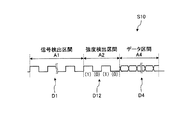
信号処理部73は、カプセル型内視鏡72が受信装置83に無線送信する送信信号を生成する信号生成部として機能する。具体的には、信号処理部73は、制御部25の制御に基づいて動作し、撮像部22が被検体1の体内画像を撮像する都度、撮像部22から体内画像データを取得し、この取得した体内画像データを含む送信信号を生成する。この場合、信号処理部73は、図13に示す信号フォーマットに基づいて、1フレーム分の体内画像データを含む1フレームの送信信号S10を生成する。すなわち、信号処理部73は、送信信号S10の先頭の信号区間である信号検出区間A1に、信号検出のための検出用データD1を有する検出信号を含め、この信号検出区間A1に後続する信号区間である強度検出区間A2に、繰り返し周期を固定したデジタルデータD12を有するデジタル信号を含め、この強度検出区間A2に後続する信号区間であるデータ区間A4に、撮像部22から取得した体内画像データD4を有する画像信号を含め、この結果、1フレームの送信信号S10を生成する。信号処理部73は、このように生成した送信信号S10を送信ユニット74に送出する。
The signal processing unit 73 functions as a signal generation unit that generates a transmission signal that the
ここで、強度検出区間A2内のデジタル信号は、周波数を零以外の所定値に固定した特定信号の一例であり、所定の繰り返し周期でデジタル値(1)とデジタル値(0)とを繰り返すデジタルデータD12(すなわちデジタル値(1)とデジタル値(0)とを繰り返すデータパターンを一定にしたデジタルデータ)によって形成される。信号処理部73は、かかるデジタルデータD12によって形成されるデジタル信号の周波数を、後述する変調部74aの搬送波周波数fcに対する周波数偏差△fcの2倍に等しい周波数に固定し、この固定した周波数(=2・△fc)のデジタル信号、すなわちデジタルデータD12を強度検出区間A2に組み込む。
Here, the digital signal in the intensity detection section A2 is an example of a specific signal in which the frequency is fixed to a predetermined value other than zero. The digital signal repeats the digital value (1) and the digital value (0) at a predetermined repetition period. It is formed by data D12 (that is, digital data in which a data pattern that repeats digital value (1) and digital value (0) is constant). The signal processing unit 73 fixes the frequency of the digital signal formed by the digital data D12 to a frequency equal to twice the frequency deviation Δfc with respect to the carrier frequency fc of the
なお、かかる信号処理部73によって送信信号S10の強度検出区間A2に組み込まれるデジタル信号の周波数(=2・△fc)は、変調部74aに強度検出区間A2のデジタル信号を入力する際の最大伝送速度fb[bps]と変調部74aの変調指数mとを用いて次式(1)によって算出される。
2・△fc=fb・m ・・・(1)
すなわち、信号処理部73は、かかる最大伝送速度fbと変調指数mとの乗算値に等しい周波数に固定したデジタル信号を送信信号S10の強度検出区間A2に組み込む。例えば、最大伝送速度fbが4M[bps]であり、変調指数mが0.5である場合、信号処理部73は、周波数を2M[Hz]に固定したデジタル信号を送信信号S10の強度検出区間A2に組み込む。
Note that the frequency (= 2 · Δfc) of the digital signal incorporated into the intensity detection section A2 of the transmission signal S10 by the signal processing unit 73 is the maximum transmission when the digital signal of the intensity detection section A2 is input to the
2 · Δfc = fb · m (1)
That is, the signal processing unit 73 incorporates a digital signal fixed at a frequency equal to the product of the maximum transmission rate fb and the modulation index m into the intensity detection section A2 of the transmission signal S10. For example, when the maximum transmission rate fb is 4M [bps] and the modulation index m is 0.5, the signal processing unit 73 uses a digital signal whose frequency is fixed to 2M [Hz] as an intensity detection interval of the transmission signal S10. Incorporate into A2.
送信ユニット74は、信号処理部73によって生成された送信信号S10をデジタル変調(具体的には最小偏移変調)して外部に無線送信するためのものである。かかる送信ユニット74は、信号処理部73によって生成された送信信号S10を最小偏移変調(MSK変調)する変調部74aと、変調部74aによって変調された送信信号S10を外部に無線送信する送信部24bとを備える。
The
変調部74aは、信号処理部73によって生成された送信信号S10をMSK変調して、少なくとも搬送波周波数成分を含む複数の狭帯域信号成分を強度検出区間A2に有する変調信号を生成する。具体的には、変調部74aは、搬送波周波数fcの搬送波信号を発信する信号発信部およびVCO等を用いて実現され、その変調指数mを0.5に設定される。かかる変調部74aは、制御部25の制御に基づいて、信号処理部73から送信信号S10を取得し、その都度、この取得した送信信号S10を搬送波信号に重畳してMSK変調処理を行う。この場合、変調部74aは、周波数を搬送波周波数fcにロックするPLL制御を行いつつ、送信信号S10をMSK変調した変調信号を生成する。
The
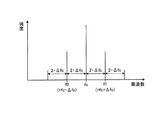
かかる変調部74aのMSK変調によって生成された変調信号は、検出用データD1に対応する広帯域信号成分を信号検出区間A1に含み、デジタルデータD12をもつデジタル信号に対応する狭帯域信号成分を強度検出区間A2に含み、体内画像データD4に対応する広帯域信号成分をデータ区間A4に含む。ここで、強度検出区間A2のデジタル信号が周波数偏差△fcの2倍に等しい周波数に固定されたデジタル信号である場合、この強度検出区間A2のデジタル信号をMSK変調した変調信号は、少なくとも搬送波周波数成分を含む複数の狭帯域信号成分を有する。すなわち、変調部74aは、上述した送信信号S10をMSK変調することによって、少なくとも搬送波周波数成分を含む複数の狭帯域信号成分を強度検出区間A2に組み込んだ変調信号を生成する。
The modulation signal generated by the MSK modulation of the
かかる変調信号の強度検出区間A2における周波数特性は、図14に示すように、搬送波周波数fc、デジタル値(0)に対応する周波数f0、デジタル値(1)に対応する周波数f1、周波数f0から低周波側に2・△fcだけシフトした周波数、および周波数f1から高周波側に2・△fcだけシフトした周波数の各々に周波数スペクトルが立ったものになる。すなわち、かかる変調信号の強度検出区間A2には、搬送波周波数fcに周波数スペクトルをもつ狭帯域信号成分と、周波数f0に周波数スペクトルをもつ狭帯域信号成分と、周波数f1に周波数スペクトルをもつ狭帯域信号成分と、周波数f0から低周波側に2・△fcだけシフトした周波数に周波数スペクトルをもつ狭帯域信号成分と、周波数f1から高周波側に2・△fcだけシフトした周波数に周波数スペクトルをもつ狭帯域信号成分とが互いに離散的な態様で組み込まれている。なお、かかる強度検出区間A2に含まれる各狭帯域信号成分の帯域幅は、例えば数10[kHz]程度である。 As shown in FIG. 14, the frequency characteristics of the modulation signal in the intensity detection section A2 are low from the carrier frequency fc, the frequency f0 corresponding to the digital value (0), the frequency f1 corresponding to the digital value (1), and the frequency f0. A frequency spectrum stands for each of the frequency shifted by 2 · Δfc to the frequency side and the frequency shifted by 2 · Δfc from the frequency f1 to the high frequency side. That is, in the intensity detection section A2 of the modulated signal, a narrowband signal component having a frequency spectrum at the carrier frequency fc, a narrowband signal component having a frequency spectrum at the frequency f0, and a narrowband signal having a frequency spectrum at the frequency f1. A narrowband signal component having a frequency spectrum at a frequency shifted by 2 · Δfc from the frequency f0 to the low frequency side, and a narrowband having a frequency spectrum at a frequency shifted by 2 · Δfc from the frequency f1 to the high frequency side The signal components are incorporated in a discrete manner. The bandwidth of each narrowband signal component included in the intensity detection section A2 is, for example, about several tens [kHz].
なお、変調部74aは、上述したようにMSK変調によって生成した変調信号を送信部24bに送出する。送信部24bは、この変調部74aから取得した変調信号を送信アンテナ24cを介して外部の受信装置83に無線送信する。
The
つぎに、上述した受信装置83の構成について詳細に説明する。図15は、本発明の実施の形態4にかかる受信装置の一構成例を示すブロック図である。図15に示すように、この実施の形態4にかかる受信装置83は、上述した実施の形態1にかかる受信装置3の受信強度検出部36に代えて受信強度検出部86を備え、画像処理部39に代えて画像処理部89を備える。かかる受信装置83において、受信強度検出系40は、狭帯域フィルタ34と中間周波数増幅器35と受信強度検出部86とによって構成され、画像処理系41は、広帯域フィルタ37と中間周波数増幅器38と画像処理部89とによって構成される。また、この実施の形態4において、周波数混合器33は、図13に示した送信信号S10をMSK変調した変調信号の高周波周波数を中間周波数にダウンコンバートし、このダウンコンバートした変調信号を受信強度検出系40と画像処理系41とに分岐して出力する。この場合、かかる周波数混合器33によって分岐された一方の変調信号S11は受信強度検出系40に入力され、他方の変調信号S12は画像処理系41に入力される。その他の構成は実施の形態1と同じであり、同一構成部分には同一符号を付している。
Next, the configuration of the receiving
受信強度検出部86は、上述した実施の形態1にかかる受信装置3の受信強度検出部36と同様の受信電界強度検出機能を有し、変調信号11の強度検出区間A2に含まれる複数の狭帯域信号成分の中から狭帯域フィルタ34によって抽出された狭帯域信号成分の受信電界強度を検出する。この場合、狭帯域フィルタ34は、この強度検出区間A2内の複数の狭帯域信号成分の中から搬送波周波数の狭帯域信号成分、すなわち、これら複数の狭帯域信号成分のうちの信号レベルが最も高く安定した搬送波信号を抽出することが望ましく、受信強度検出部86は、この狭帯域フィルタ34によって抽出された搬送波信号の受信電界強度を検出することが望ましい。なお、かかる受信強度検出部86によって検出された受信電界強度は、上述した実施の形態1の場合と同様に制御部45に送出される。
The reception
画像処理部89は、変調信号S12のデータ区間A4に含まれる体内画像データD4を信号処理して被検体1の体内画像を生成する。かかる画像処理部89は、制御部45によって動作開始を指示されてから体内画像データD4を信号処理するタイミングが異なること以外、上述した実施の形態1にかかる受信装置3の画像処理部39と同様の信号処理機能を有する。なお、かかる画像処理部89によって生成された被検体1の体内画像は、上述した実施の形態1の場合と同様に制御部45に送出される。
The image processing unit 89 performs signal processing on the in-vivo image data D4 included in the data section A4 of the modulation signal S12 to generate an in-vivo image of the
つぎに、本発明の実施の形態4にかかる受信装置83の受信強度検出部86および画像処理部89の各動作について説明する。図16は、実施の形態4にかかる受信装置の動作タイミングの一例を示す模式図である。以下では、図16を参照しつつ、上述した1フレームの送信信号S10をMSK変調した1フレームの変調信号について受信電界強度の検出および体内画像データの信号処理を実行する際の受信装置83の動作を説明する。
Next, operations of the reception
受信装置83は、アンテナ切替部30によって受信アンテナ3a〜3hの中から選択された受信アンテナを介してカプセル型内視鏡72からの変調信号を受信し、この受信した変調信号を周波数混合器33によって2つの変調信号S11,S12に分岐する。この場合、制御部45は、アンテナ切替部30に受信アンテナを選択させたタイミング(時間T0)において受信強度検出部86および画像処理部89の各動作を開始させる。
The receiving
画像処理部89は、かかる制御部45の制御に基づいて動作を開始し、この時間T0から信号検出期間△Tdが経過するまでにカプセル型内視鏡72から1フレームの変調信号が無線送信されている旨を検出する。画像処理部89は、広帯域フィルタ37を通過した変調信号S12の信号検出区間A1内の広帯域信号成分を取得し、この取得した広帯域信号成分に含まれる検出用データD1をもとに、この変調信号S12の始まりを検出する。
The image processing unit 89 starts operating based on the control of the
つぎに、受信強度検出部86は、上述した信号検出期間△Tdが経過したタイミング(時間T1)から強度検出期間△Tmが経過するまでに、この変調信号S11の受信電界強度、すなわち受信アンテナ毎の受信電界強度を検出する。具体的には、受信強度検出部86は、この時間T1からガード期間△Tgが経過するまでの期間、受信電界強度の検出処理の開始を待機し、このガード期間△Tgが経過したタイミング(時間T2)において受信電界強度の検出処理を開始する。かかる受信強度検出部86は、この強度検出期間△Tm内に、この変調信号S11の強度検出区間A2に含まれる複数の狭帯域信号成分のうちの一つ、例えば搬送波信号の受信電界強度を検出し終える。かかる受信強度検出部86によって検出された狭帯域信号成分の受信電界強度は、受信アンテナ毎の受信電界強度の検出結果として制御部45に送出される。
Next, the
一方、画像処理部89は、上述した信号検出期間△Tdが経過したタイミング(時間T1)から強度検出期間△Tmが経過したタイミング(時間T3)からデータ処理期間△Tdatが経過するまでに、変調信号S12のデータ区間A4に含まれる体内画像データD4を信号処理する。すなわち、画像処理部89は、データ処理期間△Tdat内に1フレーム分の体内画像データD4を取得し、この取得した体内画像データD4に基づいた1フレームの体内画像を生成する。画像処理部89は、この生成した1フレームの体内画像、すなわち被検体1の体内画像を制御部45に送出する。
On the other hand, the image processing unit 89 modulates the data detection period ΔTdat from the timing (time T3) after the intensity detection period ΔTm elapses from the timing (time T1) when the signal detection period ΔTd elapses. The in-vivo image data D4 included in the data section A4 of the signal S12 is signal-processed. That is, the image processing unit 89 acquires the in-vivo image data D4 for one frame within the data processing period ΔTdat, and generates a one-frame in-vivo image based on the acquired in-vivo image data D4. The image processing unit 89 sends the generated one-frame in-vivo image, that is, the in-vivo image of the subject 1 to the
その後、画像処理部89は、制御部45によって動作開始を指示されるまで待機状態になる。なお、受信強度検出部86は、上述したデータ処理期間△Tdatにおいて、変調信号S11を取得しつつ受信電界強度の検出処理の開始を待機し、制御部45によって動作開始を指示されるまで、この待機状態を継続する。かかる受信強度検出部86および画像処理部89は、制御部45によって動作開始を指示される都度、図16に示した動作タイミングに沿って上述した動作を繰り返し実行する。この結果、受信強度検出部86は、各受信アンテナの受信電界強度を順次検出し、画像処理部89は、1フレームの体内画像を順次生成する。
Thereafter, the image processing unit 89 enters a standby state until the
ここで、上述したカプセル型内視鏡72の送信信号S10の強度検出区間A2には、図13に示したように、一定のデータパターンを有するデジタルデータD12によって形成されるデジタル信号が組み込まれる。このため、かかる送信信号S10をMSK変調した変調信号(すなわち変調信号S11,S12)の強度検出区間A2には、図14に示した周波数特性を有して周波数を遷移させる変調信号が組み込まれる。なお、この強度検出区間A2内の変調信号は、少なくとも搬送波信号成分を含む複数の狭帯域信号成分を有する。かかる変調信号が強度検出区間A2に組み込まれているため、上述した送信信号S10および変調信号S11,12は、強度検出区間A2とデータ区間A4との間にアイドリング区間A3を設定しなくても、強度検出区間A2からデータ区間A4にスムーズに周波数を移行することができ、この結果、画像処理部89は、強度検出期間△Tmが終了後、上述したアイドリング期間△Tiを経ることなくデータ処理期間△Tdatに、安定した状態の体内画像データD4を取得することができる。かかる画像処理部89は、上述した実施の形態1の場合に比して短時間に体内画像データD4を信号処理することができる。
Here, in the intensity detection section A2 of the transmission signal S10 of the
以上、説明したように、本発明の実施の形態4では、一定のデータパターンを有するデジタルデータによって形成されるデジタル信号を送信信号の強度検出区間に組み込み、この送信信号をMSK変調した変調信号を無線通信によって送受信するようにし、その他を上述した実施の形態1と略同様に構成した。このため、上述した実施の形態1と同様の作用効果を享受するとともに、かかる変調信号の強度検出区間とデータ区間との間にアイドリング区間を設定しなくても、信号処理系のデータ処理期間に安定したデータ(画像データ等)を取得でき、この結果、変調信号内のデータを処理するまでに必要な時間の短縮化を促進することができる。
As described above, in the fourth embodiment of the present invention, a digital signal formed by digital data having a certain data pattern is incorporated in the intensity detection section of the transmission signal, and a modulation signal obtained by MSK modulation of this transmission signal is used. The transmission and reception are performed by wireless communication, and the others are configured in substantially the same manner as in the first embodiment. For this reason, while enjoying the same effect as
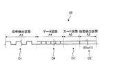
なお、上述した実施の形態1〜4では、信号フォーマットにおいてデータ区間A4の前段に強度検出区間A2を設定していたが、これに限らず、データ区間A4の後段に強度検出区間A2を設定してもよい。具体的には、実施の形態1〜3にかかるカプセル型内視鏡2の信号処理部23は、図17に示す送信信号S0のように、検出用データD1を含む信号検出区間A1を先頭の信号区間に設定し、この信号検出区間A1に後続する信号区間として、体内画像データD4を含むデータ区間A4を設定し、このデータ区間A4に後続する信号区間として、ガード区間A5を設定し、このガード区間A5に後続する信号区間として、一定デジタルデータD2を含む強度検出区間A2を設定してもよい。ここで、ガード区間A5は、データ区間A4から強度検出区間A2に信号成分が移行する際に生じる周波数の不安定な状態を解消するための信号区間であり、強度検出区間A2と同じデジタル値(0または1)を有する一定デジタルデータD5を含む。なお、実施の形態4にかかるカプセル型内視鏡72の信号処理部73は、一定のデータパターンを有するデジタルデータD12を送信信号の強度検出区間A2に組み込んでいるため、このガード区間A5を設けずに、データ区間A4に後続する信号区間として強度検出区間A2を設定してもよい。
In the first to fourth embodiments described above, the intensity detection section A2 is set before the data section A4 in the signal format. However, the present invention is not limited to this, and the intensity detection section A2 is set after the data section A4. May be. Specifically, the
このようにデータ区間A4の後段に強度検出区間A2を設定した場合、実施の形態1〜4にかかる受信装置の受信強度検出部および画像処理部は、かかる信号フォーマットに対応する動作期間(信号検出期間△Td、ガード期間△Tg、強度検出期間△Tm、データ処理期間△Tdat、アイドリング期間△Ti)を適宜設定し、この設定した動作期間に沿って受信電界強度の検出処理および体内画像データの信号処理等を実行すればよい。 As described above, when the intensity detection section A2 is set in the subsequent stage of the data section A4, the reception intensity detection unit and the image processing unit of the receiving apparatuses according to the first to fourth embodiments perform an operation period (signal detection) corresponding to the signal format. The period ΔTd, the guard period ΔTg, the intensity detection period ΔTm, the data processing period ΔTdat, the idling period ΔTi) are appropriately set, and the received electric field intensity detection process and the in-vivo image data are detected along the set operation period. What is necessary is just to perform signal processing etc.
また、上述した実施の形態1〜4では、受信装置においてカプセル型内視鏡の位置データを算出(検出)していたが、これに限らず、本発明にかかる送受信システムの画像表示装置4においてカプセル型内視鏡の位置データを算出してもよい。この場合、受信装置は、各受信アンテナの受信電界強度と体内画像とを対応付けて記録媒体5等に保存し、画像表示装置4は、かかる各受信アンテナの受信電界強度と体内画像とを取り込み、この取得した各受信電界強度を用いてカプセル型内視鏡の位置データを算出すればよい。
In
さらに、上述した実施の形態1〜4では、本発明にかかる送受信システムの送信装置としてカプセル型内視鏡2を例示したが、これに限らず、本発明にかかる送受信システムの送信装置は、被検体内部のpH値または温度等の各種体内データを所定のデータとして取得し無線送信するカプセル型医療装置であってもよいし、体内データ以外の所定のデータを無線送信する各種送信装置(医療装置以外の送信装置)であってもよい。また、本発明にかかる送受信システムの送信装置と受信装置との間で送受信される所定のデータは、上述した体内画像データに限らず、所望のデータであってもよい。すなわち、本発明にかかる受信装置の信号処理系は、この所望のデータを信号処理する信号処理系(画像処理系以外)であってもよい。
Furthermore, in Embodiment 1-4 mentioned above, although the
また、上述した実施の形態1〜4では、各受信アンテナの受信電界強度を用いるアプリケーションとして被検体内部におけるカプセル型内視鏡の位置データを算出する位置検出処理を例示したが、これに限らず、各受信アンテナの受信電界強度を必要数用いて実行される所望のアプリケーションであってもよい。 In the first to fourth embodiments described above, the position detection process for calculating the position data of the capsule endoscope inside the subject is illustrated as an application using the received electric field strength of each receiving antenna. However, the present invention is not limited to this. The desired application may be executed using the required number of received field strengths of each receiving antenna.
さらに、上述した実施の形態1〜3では、カプセル型内視鏡2の変調部24aは、信号処理部23によって生成された送信信号S0をFSK変調していたが、これに限らず、変調部24aは、FSK変調以外のデジタル変調方式(例えば、振幅偏移変調、位相偏移変調、直交振幅変調等)によって送信信号S0を変調してもよい。
Furthermore, in
1 被検体
2,72 カプセル型内視鏡
3a〜3h 受信アンテナ
3,53,63,83 受信装置
4 画像表示装置
5 記録媒体
21 照明部
22 撮像部
23,73 信号処理部
24,74 送信ユニット
24a,74a 変調部
24b 送信部
24c 送信アンテナ
25 制御部
26 電源部
30 アンテナ切替部
31 RFフィルタ
32,62 LNA
33,52,66,67 周波数混合器
34 狭帯域フィルタ
35,38,58 中間周波数増幅器
36,86 受信強度検出部
37 広帯域フィルタ
39,89 画像処理部
40,50,60 受信強度検出系
41,51,61 画像処理系
42 入力部
43 表示部
44 記憶部
45 制御部
45a 位置算出部
46 電源部
A1 信号検出区間
A2 強度検出区間
A3 アイドリング区間
A4 データ区間
A5 ガード区間
D1 検出用データ
D2,D5 一定デジタルデータ
D3,D12 デジタルデータ
D4 体内画像データ
S0,S10 送信信号
S1,S2,S11,S12 変調信号
W1,W2 通過帯域幅
DESCRIPTION OF
33, 52, 66, 67
Claims (15)
信号処理系と受信強度検出系とを具備し、3以上の受信アンテナを介して前記変調信号を受信し、受信した前記変調信号に含まれる広帯域信号成分を前記信号処理系によって処理し、前記変調信号に含まれる狭帯域信号成分を前記受信強度検出系によって処理する受信装置と、
を備えたことを特徴とする送受信システム。 A transmitter for generating a modulated signal composed of a wideband signal component and a narrowband signal component, and transmitting the modulated signal to the outside;
A signal processing system and a reception intensity detection system, receiving the modulated signal via three or more receiving antennas, processing a wideband signal component included in the received modulated signal by the signal processing system, and modulating the modulation A receiving device for processing a narrowband signal component included in the signal by the reception intensity detection system;
A transmission / reception system comprising:
前記受信装置は、前記3以上の受信アンテナを介して前記変調信号を受信して前記受信強度検出系と前記信号処理系とに前記変調信号を分岐し、この分岐した一方の変調信号の信号区間に含まれる前記狭帯域信号成分を前記受信強度検出系の狭帯域フィルタによって抽出して前記狭帯域信号成分の受信電界強度を前記受信強度検出系によって検出し、他方の変調信号のデータ区間に含まれる前記所定のデータを前記信号処理系によって信号処理することを特徴とする請求項1に記載の送受信システム。 The transmission apparatus generates a transmission signal having a signal section including a specific signal having a fixed frequency and a data section including predetermined data, and digitally modulates the transmission signal to correspond to the specific signal in the signal section. Generating the modulated signal including the narrowband signal component, and wirelessly transmitting the generated modulated signal to the outside;
The receiving apparatus receives the modulated signal via the three or more receiving antennas, branches the modulated signal to the received intensity detection system and the signal processing system, and a signal section of the one modulated signal that has been branched The narrowband signal component included in the signal is extracted by the narrowband filter of the reception intensity detection system, and the received electric field strength of the narrowband signal component is detected by the reception intensity detection system, and is included in the data section of the other modulation signal The transmission / reception system according to claim 1, wherein the predetermined data to be processed is signal-processed by the signal processing system.
前記信号区間に直流信号である前記特定信号を含み且つ前記データ区間に前記所定のデータを含む前記送信信号を生成する信号生成部と、
前記信号生成部によって生成された前記送信信号をデジタル変調して、搬送波周波数成分である前記狭帯域信号成分を前記信号区間に含む前記変調信号を生成する変調部と、
前記変調部によって生成された前記変調信号を前記受信装置に無線送信する送信部と、
を備えたことを特徴とする請求項2に記載の送受信システム。 The transmitter is
A signal generation unit that generates the transmission signal including the specific signal that is a DC signal in the signal section and including the predetermined data in the data section;
A modulation unit that digitally modulates the transmission signal generated by the signal generation unit and generates the modulation signal including the narrowband signal component that is a carrier frequency component in the signal section;
A transmitter that wirelessly transmits the modulated signal generated by the modulator to the receiver;
The transmission / reception system according to claim 2, further comprising:
搬送波周波数に対する周波数偏移の2倍に等しい周波数に固定したデジタル信号である前記特定信号を前記信号区間に含み且つ前記データ区間に前記所定のデータを含む前記送信信号を生成する信号生成部と、
前記信号生成部によって生成された前記送信信号を最小偏移変調して、少なくとも搬送波周波数成分を含む複数の前記狭帯域信号成分を前記信号区間に有する前記変調信号を生成する変調部と、
前記変調部によって生成された前記変調信号を前記受信装置に無線送信する送信部と、
を備えたことを特徴とする請求項2に記載の送受信システム。 The transmitter is
A signal generator for generating the transmission signal including the specific signal, which is a digital signal fixed to a frequency equal to twice the frequency shift with respect to the carrier frequency, in the signal interval and including the predetermined data in the data interval;
A modulation unit that performs the minimum shift modulation on the transmission signal generated by the signal generation unit, and generates the modulation signal having a plurality of the narrowband signal components including at least a carrier frequency component in the signal section;
A transmitter that wirelessly transmits the modulated signal generated by the modulator to the receiver;
The transmission / reception system according to claim 2, further comprising:
前記狭帯域フィルタは、前記狭帯域信号成分と同程度の帯域であって前記一方の変調信号の占有帯域幅に比して狭帯域な通過帯域幅を有することを特徴とする請求項2〜7のいずれか一つに記載の送受信システム。 The reception intensity detection system includes a reception intensity detection unit that detects the reception electric field intensity of the narrowband signal component extracted by the narrowband filter for each reception antenna,
The narrow band filter has a pass bandwidth that is the same band as the narrow band signal component and narrower than the occupied bandwidth of the one modulation signal. The transmission / reception system according to any one of the above.
前記狭帯域フィルタは、前記広帯域フィルタの1/10000以上、1/10以下の通過帯域幅を有することを特徴とする請求項8または9に記載の送受信システム。 The receiving device includes a wideband filter having a pass bandwidth that is approximately the same as the occupied bandwidth of the modulated signal received via the three or more receiving antennas,
10. The transmission / reception system according to claim 8, wherein the narrowband filter has a passband width of 1 / 10,000 or more and 1/10 or less of the wideband filter.
前記3以上の受信アンテナを介して受信した前記変調信号に異なる周波数の信号を混合して、前記変調信号の周波数を中間周波数に変換する周波数混合部と、
前記周波数混合部によって中間周波数に変換された前記変調信号を増幅し、この増幅した前記変調信号を前記受信強度検出系と前記信号処理系とに分岐する中間周波数増幅部と、
を備えたことを特徴とする請求項2〜10のいずれか一つに記載の送受信システム。 The receiving device is:
A frequency mixing unit that mixes signals of different frequencies with the modulated signal received via the three or more receiving antennas, and converts the frequency of the modulated signal to an intermediate frequency;
An intermediate frequency amplifying unit for amplifying the modulated signal converted to an intermediate frequency by the frequency mixing unit and branching the amplified modulated signal into the reception intensity detection system and the signal processing system;
The transmission / reception system according to any one of claims 2 to 10, further comprising:
前記3以上の受信アンテナを介して受信した前記変調信号を増幅し、この増幅した前記変調信号を前記受信強度検出系と前記信号処理系とに分岐する増幅部を備え、
前記受信強度検出系は、前記増幅部によって分岐された一方の変調信号に異なる周波数の信号を混合して、該変調信号の周波数を中間周波数に変換し、この変換した該変調信号を前記狭帯域フィルタに出力する第1の周波数混合部を備え、
前記信号処理系は、前記増幅部によって分岐された他方の変調信号に異なる周波数の信号を混合して、該変調信号の周波数を中間周波数に変換し、この変換した該変調信号を前記広帯域フィルタに出力する第2の周波数混合部を備えたことを特徴とする請求項10に記載の送受信システム。 The receiving device is:
An amplifying unit that amplifies the modulated signal received via the three or more receiving antennas and branches the amplified modulated signal into the received intensity detection system and the signal processing system;
The reception intensity detection system mixes a signal of a different frequency with one of the modulation signals branched by the amplification unit, converts the frequency of the modulation signal to an intermediate frequency, and converts the converted modulation signal to the narrowband A first frequency mixing unit for outputting to the filter;
The signal processing system mixes a signal of a different frequency with the other modulation signal branched by the amplifier, converts the frequency of the modulation signal to an intermediate frequency, and converts the converted modulation signal to the wideband filter. The transmission / reception system according to claim 10 , further comprising a second frequency mixing unit for outputting.
前記送信装置は、前記被検体内部に導入され、前記被検体の体内データを取得し、前記信号区間に前記特定信号を含み且つ前記データ区間に前記体内データを含む前記送信信号を生成し、この生成した前記送信信号をデジタル変調した前記変調信号を無線送信するカプセル型医療装置であることを特徴とする請求項2〜13のいずれか一つに記載の送受信システム。 The predetermined data is in-vivo data of a subject,
The transmission device is introduced into the subject, acquires in-vivo data of the subject, generates the transmission signal including the specific signal in the signal interval and the in-vivo data in the data interval, The transmission / reception system according to claim 2, wherein the transmission / reception system is a capsule medical device that wirelessly transmits the modulated signal obtained by digitally modulating the generated transmission signal.
前記カプセル型医療装置は、前記被検体内部の画像データを撮像する撮像部を備えたカプセル型内視鏡であることを特徴とする請求項14に記載の送受信システム。 The in-vivo data is image data inside the subject,
The transmission / reception system according to claim 14, wherein the capsule medical device is a capsule endoscope including an imaging unit that captures image data inside the subject.
Priority Applications (3)
| Application Number | Priority Date | Filing Date | Title |
|---|---|---|---|
| JP2007332936A JP5259174B2 (en) | 2007-12-25 | 2007-12-25 | Transmission / reception system |
| EP08022340A EP2074939B1 (en) | 2007-12-25 | 2008-12-23 | Transmitting/receiving system and medical system |
| US12/343,826 US8419627B2 (en) | 2007-12-25 | 2008-12-24 | Transmitting/receiving system and medical system |
Applications Claiming Priority (1)
| Application Number | Priority Date | Filing Date | Title |
|---|---|---|---|
| JP2007332936A JP5259174B2 (en) | 2007-12-25 | 2007-12-25 | Transmission / reception system |
Publications (2)
| Publication Number | Publication Date |
|---|---|
| JP2009153617A JP2009153617A (en) | 2009-07-16 |
| JP5259174B2 true JP5259174B2 (en) | 2013-08-07 |
Family
ID=40445473
Family Applications (1)
| Application Number | Title | Priority Date | Filing Date |
|---|---|---|---|
| JP2007332936A Active JP5259174B2 (en) | 2007-12-25 | 2007-12-25 | Transmission / reception system |
Country Status (3)
| Country | Link |
|---|---|
| US (1) | US8419627B2 (en) |
| EP (1) | EP2074939B1 (en) |
| JP (1) | JP5259174B2 (en) |
Families Citing this family (12)
| Publication number | Priority date | Publication date | Assignee | Title |
|---|---|---|---|---|
| WO2005074785A1 (en) * | 2004-02-06 | 2005-08-18 | Olympus Corporation | Receiver |
| JP2009148552A (en) * | 2007-11-27 | 2009-07-09 | Hoya Corp | Radio observation device and endoscope system |
| JP5006474B2 (en) * | 2009-08-28 | 2012-08-22 | オリンパスメディカルシステムズ株式会社 | Receiving system |
| KR20130136907A (en) | 2010-06-01 | 2013-12-13 | 어뎁턴스, 엘엘씨 | Systems and methods for networked wearable medical sensors |
| JP5534202B2 (en) | 2010-07-07 | 2014-06-25 | ソニー株式会社 | Transmission / reception system |
| WO2012166907A2 (en) * | 2011-05-31 | 2012-12-06 | Plum Labs, Llc | Mobile communications devices and methods having reduced communication latency |
| US8897344B2 (en) | 2011-05-31 | 2014-11-25 | Facebook, Inc. | Establishing communication |
| WO2013058277A1 (en) * | 2011-10-21 | 2013-04-25 | オリンパスメディカルシステムズ株式会社 | Antenna connection unit, receiver, received signal strength correction device, capsule endoscopic system, correction method and program |
| JP5814960B2 (en) * | 2013-02-25 | 2015-11-17 | 株式会社東芝 | Electronic thermometer, receiver and electronic thermometer system |
| WO2017176840A1 (en) | 2016-04-05 | 2017-10-12 | Wilson Electronics, Llc | Narrowband signal detection for network protection |
| CN114423471A (en) * | 2019-05-29 | 2022-04-29 | 因库博实验室有限责任公司 | Apparatus and method for administering therapeutic agents |
| CN111885355A (en) * | 2020-07-21 | 2020-11-03 | 深圳市资福医疗技术有限公司 | Communication method of capsule endoscope |
Family Cites Families (15)
| Publication number | Priority date | Publication date | Assignee | Title |
|---|---|---|---|---|
| IL108352A (en) | 1994-01-17 | 2000-02-29 | Given Imaging Ltd | In vivo video camera system |
| US5984875A (en) * | 1997-08-22 | 1999-11-16 | Innotek Pet Products, Inc. | Ingestible animal temperature sensor |
| US7151759B1 (en) * | 2001-03-19 | 2006-12-19 | Cisco Systems Wireless Networking (Australia) Pty Limited | Automatic gain control and low power start-of-packet detection for a wireless LAN receiver |
| US6934573B1 (en) * | 2001-07-23 | 2005-08-23 | Given Imaging Ltd. | System and method for changing transmission from an in vivo sensing device |
| JP3465707B1 (en) * | 2002-05-27 | 2003-11-10 | 日本電気株式会社 | Carrier sense multiple access receiver and its interference suppression method |
| JP2004310402A (en) | 2003-04-07 | 2004-11-04 | Matsushita Electric Ind Co Ltd | In-vehicle wireless device |
| JP4025749B2 (en) * | 2004-05-10 | 2007-12-26 | オリンパス株式会社 | Transmitting apparatus and in-subject introduction system |
| US7436905B2 (en) * | 2004-07-05 | 2008-10-14 | Sharp Kabushiki Kaisha | Receiver device, communications device, wireless LAN device, power control method for a receiver device, power control program for a receiver device, and storage medium |
| US20080193139A1 (en) * | 2004-12-01 | 2008-08-14 | Ido Bettesh | Two-Way Communication in an Autonomous in Vivo Device |
| JP4015666B2 (en) | 2005-04-07 | 2007-11-28 | オリンパスメディカルシステムズ株式会社 | In-subject information acquisition system |
| JP2006296971A (en) * | 2005-04-25 | 2006-11-02 | Olympus Medical Systems Corp | Receiver |
| JP4855759B2 (en) * | 2005-10-19 | 2012-01-18 | オリンパス株式会社 | Receiving apparatus and in-subject information acquisition system using the same |
| EP2063785A4 (en) * | 2006-09-06 | 2011-08-31 | Innurvation Inc | System and method for acoustic information exchange involving an ingestible low power capsule |
| JP4312780B2 (en) | 2006-09-25 | 2009-08-12 | シャープ株式会社 | Receiving device, communication device, wireless LAN device, receiving device control method, receiving device control program, recording medium |
| US20080158076A1 (en) * | 2006-12-28 | 2008-07-03 | Broadcom Corporation | Dynamically adjustable narrow bandwidth antenna for wide band systems |
-
2007
- 2007-12-25 JP JP2007332936A patent/JP5259174B2/en active Active
-
2008
- 2008-12-23 EP EP08022340A patent/EP2074939B1/en not_active Not-in-force
- 2008-12-24 US US12/343,826 patent/US8419627B2/en active Active
Also Published As
| Publication number | Publication date |
|---|---|
| EP2074939B1 (en) | 2011-08-31 |
| US8419627B2 (en) | 2013-04-16 |
| US20090163772A1 (en) | 2009-06-25 |
| JP2009153617A (en) | 2009-07-16 |
| EP2074939A1 (en) | 2009-07-01 |
Similar Documents
| Publication | Publication Date | Title |
|---|---|---|
| JP5259174B2 (en) | Transmission / reception system | |
| US7881668B2 (en) | Receiving apparatus for swallow-type capsule endoscope | |
| KR100741217B1 (en) | Radio-type in-subject information acquisition system and outside-subject device | |
| JP4493573B2 (en) | Receiver | |
| CN110799085A (en) | Wireless endoscope and wireless endoscope system | |
| US9655500B2 (en) | Receiving device | |
| US7999845B2 (en) | Electronic endoscope system | |
| EP1707106B1 (en) | Electronic endoscope apparatus | |
| US20210330180A1 (en) | Capsule endoscope system and receiving device | |
| JP2007068895A (en) | Inspection method of disconnection | |
| WO2007029818A1 (en) | Receiver apparatus, monitor apparatus, and intra-subject information acquiring system using them | |
| JP2007089892A (en) | Apparatus introduced into subject, apparatus used outside of subject, and system introduced into subject | |
| WO2007091556A1 (en) | Relay unit | |
| JP2001046334A (en) | Endoscope device | |
| WO2020202490A1 (en) | Wireless endoscope device | |
| JP2001231739A (en) | Endoscope apparatus and video camera for endoscope | |
| CN101267763A (en) | receiving device | |
| JP4804831B2 (en) | In-subject information acquisition system | |
| JP2005334080A (en) | Apparatus introduced into subject and medical instrument | |
| JP2005103147A (en) | Radio type intra-examinee-body information acquisition device and radio type intra-examinee-body information acquisition system | |
| JP2001309884A (en) | Endoscope apparatus and video camera for endoscope | |
| JP6346715B1 (en) | Receiving system | |
| JP4542398B2 (en) | Receiver | |
| JP2006271433A (en) | Electronic endoscope | |
| JP2006296971A (en) | Receiver |
Legal Events
| Date | Code | Title | Description |
|---|---|---|---|
| A621 | Written request for application examination |
Free format text: JAPANESE INTERMEDIATE CODE: A621 Effective date: 20101005 |
|
| A977 | Report on retrieval |
Free format text: JAPANESE INTERMEDIATE CODE: A971007 Effective date: 20120830 |
|
| A131 | Notification of reasons for refusal |
Free format text: JAPANESE INTERMEDIATE CODE: A131 Effective date: 20120925 |
|
| A521 | Request for written amendment filed |
Free format text: JAPANESE INTERMEDIATE CODE: A523 Effective date: 20121018 |
|
| TRDD | Decision of grant or rejection written | ||
| A01 | Written decision to grant a patent or to grant a registration (utility model) |
Free format text: JAPANESE INTERMEDIATE CODE: A01 Effective date: 20130402 |
|
| A61 | First payment of annual fees (during grant procedure) |
Free format text: JAPANESE INTERMEDIATE CODE: A61 Effective date: 20130424 |
|
| FPAY | Renewal fee payment (event date is renewal date of database) |
Free format text: PAYMENT UNTIL: 20160502 Year of fee payment: 3 |
|
| R151 | Written notification of patent or utility model registration |
Ref document number: 5259174 Country of ref document: JP Free format text: JAPANESE INTERMEDIATE CODE: R151 |
|
| S111 | Request for change of ownership or part of ownership |
Free format text: JAPANESE INTERMEDIATE CODE: R313111 |
|
| R350 | Written notification of registration of transfer |
Free format text: JAPANESE INTERMEDIATE CODE: R350 |
|
| S531 | Written request for registration of change of domicile |
Free format text: JAPANESE INTERMEDIATE CODE: R313531 |
|
| R350 | Written notification of registration of transfer |
Free format text: JAPANESE INTERMEDIATE CODE: R350 |
|
| R250 | Receipt of annual fees |
Free format text: JAPANESE INTERMEDIATE CODE: R250 |
|
| R250 | Receipt of annual fees |
Free format text: JAPANESE INTERMEDIATE CODE: R250 |
|
| R250 | Receipt of annual fees |
Free format text: JAPANESE INTERMEDIATE CODE: R250 |
|
| R250 | Receipt of annual fees |
Free format text: JAPANESE INTERMEDIATE CODE: R250 |
|
| R250 | Receipt of annual fees |
Free format text: JAPANESE INTERMEDIATE CODE: R250 |
|
| R250 | Receipt of annual fees |
Free format text: JAPANESE INTERMEDIATE CODE: R250 |
|
| R250 | Receipt of annual fees |
Free format text: JAPANESE INTERMEDIATE CODE: R250 |