JP5254739B2 - Image forming apparatus and control method thereof - Google Patents
Image forming apparatus and control method thereof Download PDFInfo
- Publication number
- JP5254739B2 JP5254739B2 JP2008274865A JP2008274865A JP5254739B2 JP 5254739 B2 JP5254739 B2 JP 5254739B2 JP 2008274865 A JP2008274865 A JP 2008274865A JP 2008274865 A JP2008274865 A JP 2008274865A JP 5254739 B2 JP5254739 B2 JP 5254739B2
- Authority
- JP
- Japan
- Prior art keywords
- pixel
- image
- output
- sub
- scanning direction
- Prior art date
- Legal status (The legal status is an assumption and is not a legal conclusion. Google has not performed a legal analysis and makes no representation as to the accuracy of the status listed.)
- Expired - Fee Related
Links
Images


Classifications
-
- G—PHYSICS
- G02—OPTICS
- G02B—OPTICAL ELEMENTS, SYSTEMS OR APPARATUS
- G02B26/00—Optical devices or arrangements for the control of light using movable or deformable optical elements
- G02B26/08—Optical devices or arrangements for the control of light using movable or deformable optical elements for controlling the direction of light
- G02B26/10—Scanning systems
-
- H—ELECTRICITY
- H04—ELECTRIC COMMUNICATION TECHNIQUE
- H04N—PICTORIAL COMMUNICATION, e.g. TELEVISION
- H04N1/00—Scanning, transmission or reproduction of documents or the like, e.g. facsimile transmission; Details thereof
- H04N1/04—Scanning arrangements, i.e. arrangements for the displacement of active reading or reproducing elements relative to the original or reproducing medium, or vice versa
-
- G—PHYSICS
- G03—PHOTOGRAPHY; CINEMATOGRAPHY; ANALOGOUS TECHNIQUES USING WAVES OTHER THAN OPTICAL WAVES; ELECTROGRAPHY; HOLOGRAPHY
- G03G—ELECTROGRAPHY; ELECTROPHOTOGRAPHY; MAGNETOGRAPHY
- G03G15/00—Apparatus for electrographic processes using a charge pattern
-
- H—ELECTRICITY
- H04—ELECTRIC COMMUNICATION TECHNIQUE
- H04N—PICTORIAL COMMUNICATION, e.g. TELEVISION
- H04N1/00—Scanning, transmission or reproduction of documents or the like, e.g. facsimile transmission; Details thereof
- H04N1/40—Picture signal circuits
- H04N1/405—Halftoning, i.e. converting the picture signal of a continuous-tone original into a corresponding signal showing only two levels
- H04N1/4051—Halftoning, i.e. converting the picture signal of a continuous-tone original into a corresponding signal showing only two levels producing a dispersed dots halftone pattern, the dots having substantially the same size
- H04N1/4052—Halftoning, i.e. converting the picture signal of a continuous-tone original into a corresponding signal showing only two levels producing a dispersed dots halftone pattern, the dots having substantially the same size by error diffusion, i.e. transferring the binarising error to neighbouring dot decisions
-
- H—ELECTRICITY
- H04—ELECTRIC COMMUNICATION TECHNIQUE
- H04N—PICTORIAL COMMUNICATION, e.g. TELEVISION
- H04N1/00—Scanning, transmission or reproduction of documents or the like, e.g. facsimile transmission; Details thereof
- H04N1/40—Picture signal circuits
- H04N1/405—Halftoning, i.e. converting the picture signal of a continuous-tone original into a corresponding signal showing only two levels
- H04N1/4055—Halftoning, i.e. converting the picture signal of a continuous-tone original into a corresponding signal showing only two levels producing a clustered dots or a size modulated halftone pattern
- H04N1/4056—Halftoning, i.e. converting the picture signal of a continuous-tone original into a corresponding signal showing only two levels producing a clustered dots or a size modulated halftone pattern the pattern varying in one dimension only, e.g. dash length, pulse width modulation [PWM]
Landscapes
- Engineering & Computer Science (AREA)
- Multimedia (AREA)
- Signal Processing (AREA)
- Physics & Mathematics (AREA)
- General Physics & Mathematics (AREA)
- Optics & Photonics (AREA)
- Image Processing (AREA)
- Facsimile Image Signal Circuits (AREA)
- Color, Gradation (AREA)
Description
本発明は画像形成装置およびその制御方法に関し、特に、像担持体での露光走査および現像によって可視像を形成し、記録媒体に転写する画像形成装置において、多値誤差拡散処理を適用する画像形成装置およびその制御方法に関する。
BACKGROUND OF THE
従来より、入力多値データを、より少ないレベルの多値データで表現するために、擬似中間調処理が用いられる。擬似中間調処理とは、入力された多値階調の画像データを、例えば白点と黒点のみを用いた2値画像として表現する場合に、多値階調をより自然に表現させるための画像処理方法である。この擬似中間調処理の代表例として誤差拡散法が知られている(例えば、非特許文献1参照)。しかしながら、誤差拡散法をレーザプリンタのような電子写真方式の画像形成装置に対して適用すると、ドット安定性が良好でない場合が発生した、
この問題を改善する方法として、FMスクリーン処理を行った後にAMスクリーン処理を行ってドットサイズ及びドット密度を調整するにより、プリンタにおけるデータノイズ(アーティファクト)や変動を受けにくい擬似中間調処理が提案されている。(例えば、特許文献1参照)。
As a method of improving this problem, pseudo halftone processing is proposed which is less susceptible to data noise (artifacts) and fluctuations in the printer by adjusting the dot size and dot density by performing AM screen processing after FM screen processing. ing. (For example, refer to Patent Document 1).
しかしながら、従来の誤差拡散法による擬似中間調処理では、スクリーン処理と比較して粒状性、ドット安定性を満足できないという問題があった。 However, the conventional pseudo-halftone process using the error diffusion method has a problem that the graininess and dot stability cannot be satisfied as compared with the screen process.
本発明は上述した問題を解決するためになされたものであり、画像形成装置において多値誤差拡散処理を行った場合に、粒状性およびドット安定性の改善を可能とする画像形成装置およびその制御方法を提供することを目的とする。 The present invention has been made to solve the above-described problem, and an image forming apparatus capable of improving graininess and dot stability when multilevel error diffusion processing is performed in the image forming apparatus, and control thereof. It aims to provide a method.
上記目的を達成するための一手段として、本発明の画像形成装置は以下の構成を備える。 As a means for achieving the above object, an image forming apparatus of the present invention comprises the following arrangement.
すなわち、像担持体での露光走査および現像によって可視像を形成し、記録媒体に転写する画像形成装置であって、
入力画像に対し、前記記録媒体の搬送方向である副走査方向に隣接する2画素を平均化することによって、該副走査方向のサイズを1/2に縮小する平均化手段と、
前記平均化手段からの出力画像に対し、多値誤差拡散処理を施す多値誤差拡散手段と、
前記多値誤差拡散手段からの出力画像における各画素を、前記副走査方向に隣接し、異なる画素値を持つ2画素に置き換える2画素化手段と、
前記2画素化手段からの出力画像に対し、画素位置に応じて副走査方向に隣接する画素値を入れ替えた画像を出力する出力手段と、
前記出力手段からの出力画像に基づいて、前記露光走査を行うための露光制御信号を生成する露光制御信号の生成手段と、を有することを特徴とする。
That is, an image forming apparatus that forms a visible image by exposure scanning and development on an image carrier and transfers it to a recording medium,
Averaging means for reducing the size in the sub-scanning direction to ½ by averaging two pixels adjacent to the input image in the sub-scanning direction that is the conveyance direction of the recording medium;
Multi-value error diffusion means for performing multi-value error diffusion processing on the output image from the averaging means;
2-pixel conversion means for replacing each pixel in the output image from the multi-value error diffusion means with two pixels adjacent in the sub-scanning direction and having different pixel values ;
Output means for outputting an image in which pixel values adjacent to each other in the sub-scanning direction are changed according to the pixel position with respect to the output image from the two-pixel conversion means;
Exposure control signal generating means for generating an exposure control signal for performing the exposure scanning based on an output image from the output means.
例えば、前記2画素化手段は、前記多値誤差拡散手段からの出力画像がとりうる画素値に対し、それぞれに対応する2画素分の画素値の組を予め設定しておき、該画素値の組は、2画素分の画素値が互いに異なる第1の組と、2画素分の画素値が互いに等しい第2の組を有することを特徴とする。 For example, the two-pixel conversion unit sets in advance a pair of pixel values for two pixels corresponding to the pixel values that can be taken by the output image from the multi-value error diffusion unit, The set includes a first set having different pixel values for two pixels and a second set having equal pixel values for two pixels.
例えば、前記第1の組においては、置き換え時に副走査方向における一方側に相当する画素の画素値が、他方側に相当する画素の画素値よりも大きいことを特徴とする。 For example, in the first set, the pixel value corresponding to one side in the sub-scanning direction at the time of replacement is larger than the pixel value corresponding to the pixel corresponding to the other side.
上記構成からなる本発明によれば、画像形成装置において多値誤差拡散処理を行った場合に、粒状性およびドット安定性を改善することができる。 According to the present invention having the above-described configuration, it is possible to improve graininess and dot stability when multilevel error diffusion processing is performed in an image forming apparatus.
以下に本願発明の一実施形態を示す。もちろん以下の実施形態は、本願発明の技術分野における当業者による実施を容易にするために開示を提供するものであり、特許請求の範囲によって確定される本願発明の技術的範囲に含まれるほんの一部の実施形態にすぎない。従って、本願明細書に直接的に記載されていない実施形態であっても、技術思想が共通する限り本願発明の技術的範囲に包含されることは当業者にとって自明であろう。 An embodiment of the present invention is shown below. Of course, the following embodiments are provided for facilitating implementation by those skilled in the art of the present invention, and are only included in the technical scope of the present invention defined by the claims. It is only an embodiment of the part. Therefore, it will be apparent to those skilled in the art that even embodiments that are not directly described in the present specification are included in the technical scope of the present invention as long as they share the same technical idea.
なお、便宜上複数の実施形態を記載するが、これらは個別に発明として成立するだけでなく、もちろん、複数の実施形態を適宜組み合わせることでも発明が成立することは、当業者であれば容易に理解できよう。 Note that although a plurality of embodiments are described for convenience, those skilled in the art can easily understand that these are not only individually established as inventions, but of course that the invention can also be realized by appropriately combining a plurality of embodiments. I can do it.
<第1実施形態>
●プリンタ構成
図14は、本実施形態における画像形成装置の構造断面図である。同図に示されるように、本実施形態の画像形成装置は4ドラム方式のカラーレーザビームプリンタの構造を有する。
<First Embodiment>
Printer Configuration FIG. 14 is a structural cross-sectional view of the image forming apparatus in the present embodiment. As shown in the figure, the image forming apparatus of this embodiment has a structure of a four-drum type color laser beam printer.
この画像形成装置は、下部に転写材カセット53を装着している。転写材カセット53にセットされた記録媒体(記録紙、透過シート等)は、給紙ローラ54によって一枚ずつ取り出され、搬送ローラ対55a,55bによって画像形成部に給送される。画像形成部には、記録媒体を搬送する転写搬送ベルト10が、複数の回転ローラによって記録媒体搬送方向(図2では右側から左側方向)に扁平に張設され、その最上流部においては、記録媒体が転写搬送ベルト10に静電吸着される。またこのベルト搬送面に対向して4個のドラム状の像担持体としての感光ドラム14C,14Y,14M,14Kが直線状に配設されて、画像形成部を構成している(ここで、Cはシアン、Yはイエロー、Mはマゼンタ、Kはブラックの各色成分を示している)。
In this image forming apparatus, a
なお、画像形成部においては複数色の画像を形成するが、各色ごとに画像を形成するための構成(以下、色像形成部と称する)においては、搭載する記録剤(トナー)の色が異なるだけで、構造上の違いはない。したがって以下では、C色成分の画像形成を行うC色像形成部について説明する。 The image forming unit forms a plurality of color images. However, in the configuration for forming an image for each color (hereinafter referred to as a color image forming unit), the color of the mounted recording agent (toner) is different. There is no structural difference. Therefore, a C color image forming unit that forms an image of the C color component will be described below.
C色像形成部は、感光ドラム14Cの表面を一様に帯電させる帯電器50C、C色トナーを収納し、感光ドラム14C上に生成された静電潜像を現像して可視像化する現像器52C、並びに、露光部51Cを有する。現像器52Cと帯電器50Cとの間には、所定の間隙が設けられている。帯電器50Cによってその表面が均一に帯電した感光ドラム14C上に、上記の間隙を介してレーザスキャナからなる露光部51Cからのレーザ光が図面に垂直な方向に露光走査される。これにより、露光走査した部分が非露光部分と異なる帯電状態となり、すなわち静電潜像が生成される。現像器52Cは上記静電潜像にトナーを転移させて顕像化(トナー像化;現像)することにより、可視像が形成される。
The C color image forming unit stores a
また、転写搬送ベルト10の搬送面を挟んで転写部57Cが配置されている。感光ドラム14Cの周面上に形成(現像)されたトナー像は、転写部57で形成される転写電界によって、搬送されてきた記録媒体上に電荷吸着されて、記録媒体面上に転写される。
Further, a transfer portion 57 </ b> C is disposed across the conveyance surface of the
上記色成分Cについての処理を、他の色成分Y,M,Kの色像形成部についても同様に行うことで、C,M,Y,Kの各色トナー像が、記録媒体上に次々と転写され、重畳されることになる。その後、定着器58により、記録媒体上に重畳された各色トナーを熱溶融して定着させ、排紙ローラ対59a,59bによって該記録媒体が機外に排出される。
By performing the processing for the color component C in the same manner for the color image forming portions of the other color components Y, M, and K, the respective color toner images of C, M, Y, and K are successively formed on the recording medium. It will be transferred and superimposed. Thereafter, the color toner superimposed on the recording medium is melted and fixed by the
なお、以上は各色成分のトナー像を記録媒体上に直接転写する例を示したが、本発明に適用可能な画像形成装置はこのような構成に限定されない。例えば、各色成分のトナー像を、一旦、転写搬送ベルト上に転写した後、該転写搬送ベルトに生成されたトナー像を記録媒体に転写する(二次転写)する構成でも構わない。このような二次転写を行う場合の転写ベルトを、中間転写ベルトという。 In the above, the toner image of each color component is directly transferred onto the recording medium. However, the image forming apparatus applicable to the present invention is not limited to such a configuration. For example, the toner image of each color component may be once transferred onto a transfer conveyance belt, and then the toner image generated on the transfer conveyance belt may be transferred to a recording medium (secondary transfer). A transfer belt for performing such secondary transfer is referred to as an intermediate transfer belt.
●装置構成および処理概要
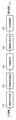
図1は、本実施形態の画像形成部において、形成対象となる入力画像に基づき、露光制御信号を生成するまでの画像処理を行うための構成例を示すブロック図である。同図に示す構成は専用ハードウェアによって実現することも可能であり、また、ソフトウェアによって実現することも可能である。
Apparatus Configuration and Process Overview FIG. 1 is a block diagram illustrating a configuration example for performing image processing until an exposure control signal is generated based on an input image to be formed in the image forming unit of the present embodiment. . The configuration shown in the figure can be realized by dedicated hardware, or can be realized by software.
図1において、101は2画素平均化部であり、102は多値誤差拡散部、103は2画素化部、104は濃度値入れ替え部、105はPWM変換部である。なお、これらの各構成においては、形成対象となる入力画像の色成分ごとに、処理を行うとする。以下、各部の動作についての概要を説明する。 In FIG. 1, 101 is a two-pixel averaging unit, 102 is a multi-value error diffusion unit, 103 is a two-pixel conversion unit, 104 is a density value replacement unit, and 105 is a PWM conversion unit. In each of these configurations, it is assumed that processing is performed for each color component of the input image to be formed. Hereinafter, an outline of the operation of each unit will be described.
まず2画素平均化部101では、入力画像の副走査方向に隣接する2画素の平均を取り、副走査方向の解像度を1/2にする。次に多値誤差拡散部102では、2画素平均化部101より入力された多値画像データを、量子化代表値に量子化(擬似中間調処理)し、該量子化代表値を2画素化部103へと渡す。2画素化部103では、多値誤差拡散部102より出力された量子化代表値を、副走査方向に対して2画素の濃度値に変換することによって、解像度を元画像同等に戻し、濃度値入れ替え部104へと渡す。濃度値入れ替え部104では、2画素化部103より出力された濃度値に対し、市松状に配置された2×2画素ブロック単位で、上下の値、すなわち副走査方向に隣接する画素値を入れ替えることにより、濃ブロックおよび淡ブロックが生成される。
First, the two-pixel averaging
入れ替え後の出力はPWM変換部105へと渡され、周知のパルス幅変調によって露光制御信号に変換される。以下、各部の詳細な動作について説明する。
The output after the replacement is passed to the
●2画素平均化処理
2画素平均化部101では、255階調の画像データを入力として、2画素平均化処理を行う。ここで図3に、2画素平均化処理の具体例を示す。図3の301,302に示すように、本実施形態の2画素平均化処理においては、入力された255階調の画像データを、副走査方向に対して{(上の画素値)+(下の画素値)}/2とした値を出力する。この平均化処理を、画像全領域に実施する。303に2画素平均処理前の入力画像の画素値例を示し、304に、303の画像を2画素平均化した後の画素値例を示す。同図からも分かるように、2画素平均化処理により画像サイズは副走査方向に縮小される。このように2画素平均化された画像は、多値誤差拡散部102へ渡される。
2-Pixel Averaging Processing The 2-
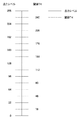
●多値誤差拡散処理
多値誤差拡散部102では、例えば9値の多値誤差拡散による擬似中間調処理を行うとする。例えば図4に示すように、2画素平均化部101より入力される画素値に対し、周辺の量子化誤差を拡散係数により重み付け加算した値を、以下に示す各閾値と比較して、量子化代表値を決定する。すなわち、入力画素値をxとすると、量子化代表値Pは以下のようになる。
Multi-level error diffusion processing The multi-level
x<16 の時、P=0
16≦x<48 の時、P=32
48≦x<80 の時、P=64
80≦x<112 の時、P=96
112≦x<144 の時、P=128
144≦x<176 の時、P=160
176≦x<208 の時、P=224
208≦x<240 の時、P=240
240≦x の時、P=255
多値誤差拡散部102では、入力画素値に周辺の量子化誤差を重み付け加算した値と、量子化代表値と、の差分を量子化誤差として、未処理の周辺画素に拡散する。このときに用いる拡散係数及び拡散する範囲については特に限定しない。このような多値誤差拡散処理によって得られた量子化代表値は、2画素化部103へ渡される。
P = 0 when x <16
When 16 ≦ x <48, P = 32
When 48 ≦ x <80, P = 64
When 80 ≦ x <112, P = 96
When 112 ≦ x <144, P = 128
When 144 ≦ x <176, P = 160
When 176 ≦ x <208, P = 224
When 208 ≦ x <240, P = 240
When 240 ≦ x, P = 255
The multi-level
●2画素化処理
2画素化部103では、多値誤差拡散部102によって擬似中間調処理が施された後の画像データに対し、その画素ごとに、それぞれ2画素分の出力値を決定し、1画素のデータを副走査方向に2画素分のデータに変換する。上述した2画素平均化部101の2画素平均化処理によって、入力画像の解像度(画素数)が副走査方向に対して1/2に縮小されているため、ここでの2画素化処理によって入力画像の解像度(画素数)が復元される。図5に、2画素化処理の具体例を示す。上述した多値誤差拡散部102による量子化により、入力される画素値は限定されるが、本実施形態では、各入力画素値について、出力すべき2画素分の画素値の組を予め設定しておく。例えば、同図の501に示すように、255の入力値に対しては2画素とも255を出力するとする。また502に示すように、224の入力値に対しては一方を255、他方を192として出力する。また503に示すように、48の入力値に対しては一方を80、他方を16として出力する。また504に示すように、0の入力値に対しては2画素とも0を出力するとする。
2-Pixelization Processing The 2-
このように本実施形態の2画素値化処理においては、入力画素値の最大値(255)と最小値(0)以外の値については、出力する2画素の値に差を設けることを特徴とする。すなわち、置き換え対象となる画素値の組として、2画素分の画素値が互いに異なる第1の組と、2画素分の画素値が互いに等しい第2の組を有し、該第2の組が、最大および最小の入力画素値に対応する。 As described above, the two-pixel value processing according to the present embodiment is characterized in that a difference is provided between the two pixel values to be output for values other than the maximum value (255) and the minimum value (0) of the input pixel values. To do. That is, as a set of pixel values to be replaced, there are a first set in which pixel values for two pixels are different from each other, and a second set in which pixel values for two pixels are equal to each other, , Corresponding to the maximum and minimum input pixel values.
画素値の組における画素値の差としては、置き換え時に例えば副走査方向における上側に相当する一方を大きな値とし、下側に相当する他方を小さな値とする、またはその逆とする等、その大小関係を固定とする。すなわち、上記第1の組においては、置き換え時に副走査方向における一方側に相当する画素の画素値が、他方側に相当する画素の画素値よりも大きいことを特徴とする。なお、ここで設定される差の大きさについては、実際の画像形成状態に基づいて定めれば良い。 The difference between the pixel values in the set of pixel values is, for example, a large value such that one corresponding to the upper side in the sub-scanning direction is a large value and the other corresponding to the lower side is a small value or vice versa. The relationship is fixed. That is, the first set is characterized in that the pixel value corresponding to one side in the sub-scanning direction is larger than the pixel value corresponding to the other side during replacement. Note that the magnitude of the difference set here may be determined based on the actual image forming state.
なお、2画素化部103での置き換え対象となる画素値の組の割り当ては、種々の方法によって実現されるため、本実施形態では特に限定しない。例えば、副走査方向2画素分の値(すなわち画素値の組そのまま)をLUTとして持つ方法や、該2画素のうち、一方の値をLUTとして持ち、他方の値を計算式により算出する方法がある。また、多値誤差拡散処理の出力値に対して所定の比率を乗ずる等、所定の演算によって2画素分の画素値を決定する方法がある。なお、画素値の組は色プレーンで異なっていても良いことはもちろんである。
Note that the assignment of a set of pixel values to be replaced in the two-
以上のような2画素化処理後の出力は、濃度値入れ替え部104へ渡される。
The output after the two-pixel processing as described above is passed to the density
●濃度値入れ替え処理
濃度値入れ替え部104における具体的な処理について、図6A,図6Bを用いて説明する。図6Aは、2画素化部103の出力例であり、各画素の濃度値を、主走査方向における斜線部の幅によって示してある。図6Aによれば、上述した2画素化処理により、副走査方向に交互に、濃ラインと淡ラインが現れていることが分かる。
Density Value Replacement Processing Specific processing in the density
濃度値入れ替え部104では、図6Aに示す画像について、全体を2×2画素ブロックに分割した際に主走査方向、副走査方向ともに交互に、すなわち市松状に配置されるブロックにおいて、上下(副走査方向)の濃度の入れ替えを行う。図6Aに示す例では、画素ブロック601,602(以下、入れ替え対象ブロック)において濃度の入れ替えが行われ、それぞれが図6Bに示す画素ブロック603,604のように変換される。
In the density
図6Bに示す入れ替え後の画像によれば、2×2画素ブロック単位で、濃いドットの集まりである濃ブロック(例えば図6Bの605)と、薄いドットの集まりである淡ブロック(例えば図6Bの606)が発生していることが分かる。 According to the image after replacement shown in FIG. 6B, a dark block (for example, 605 in FIG. 6B) that is a collection of dark dots and a light block (for example, in FIG. 6B) that is a collection of thin dots in 2 × 2 pixel block units. 606) occurs.
濃度値入れ替え部104の出力は、PWM変換部105へ渡される。
The output of the density
●PWM変換処理
PWM変換部105における具体的な処理について、図7A,図7Bを用いて説明する。PWM変換部105では、上述した図6Bに示した濃度値入れ替え後の画像に対し、パルス幅変調(PWM)を施すことによって、各色像形成部における感光体への露光信号(PWM信号)に変換する。図7Aは、このPWM変換後の露光信号(PWM信号)の例を示す。図7Aにおいて、701が図6Bにおける濃ブロック605に対応し、702が同じく淡ブロック606に対応している。図7Aに示すように本実施形態のPWM変換処理においては、主走査方向に対して奇数番目の画素については右方向から、偶数番目の画素については左方向からドットが成長するように、成長方向が制御される。したがって図7Aに示す全ての2×2画素ブロックにおいては、該ブロック内における主走査方向の中央に、PWM信号が集中するように生成される。
PWM Conversion Processing Specific processing in the
図7Bは、図7Aに示すPWM信号に対し、実際に露光走査されたドットの出力イメージを示す。図7Bによれば、本実施形態におけるPWM制御により、露光領域を集中させることができ、安定したドット再現が可能となることが分かる。 FIG. 7B shows an output image of dots actually subjected to exposure scanning with respect to the PWM signal shown in FIG. 7A. According to FIG. 7B, it can be seen that the exposure control can be concentrated by the PWM control in this embodiment, and stable dot reproduction is possible.
●処理の流れ
ここで、本実施形態における画像処理の流れについて、図2のフローチャートを用いて説明する。
Processing Flow Here, the flow of image processing in the present embodiment will be described using the flowchart of FIG.
まずステップS201において2画素平均化処理を行い、次にステップS202において、2画素平均化後の画像に対して多値誤差拡散処理を行う。そして次にステップS203において、多値誤差拡散後の画像に対して2画素化処理を行い、次にステップS204において、2画素化後の画像に対して濃度値入れ替え処理を施すか否かを判断する。この判断はすなわち、現在の処理対象である画素が、図6Aに示した入れ替えブロックに相当するか否かに応じて行う。濃度入れ替えを行うと判断した場合には、ステップS205にて、2画素化後の画像に対して濃度入れ替え処理を行った後、ステップS206に進むが、濃度入れ替えを行わないと判断した場合には、そのままステップS206に進む。 First, in step S201, a two-pixel averaging process is performed, and in step S202, a multilevel error diffusion process is performed on the image after the two-pixel averaging. Then, in step S203, a two-pixel conversion process is performed on the image after multilevel error diffusion, and in step S204, it is determined whether or not a density value replacement process is performed on the two-pixel conversion image. To do. That is, this determination is made depending on whether or not the pixel that is the current processing target corresponds to the replacement block shown in FIG. 6A. If it is determined that the density replacement is to be performed, the density replacement process is performed on the image after the two-pixel conversion in step S205, and then the process proceeds to step S206. However, if it is determined that the density replacement is not performed, The process proceeds to step S206 as it is.
ステップS206では、濃度値入れ替え後の画像がPWM変換処理で露光信号(PWM信号)に変換され、現在の処理プレーンに対応する露光部51C,M,Y,Kに出力される。上記の一連の処理が完了すると、ステップS207にて、入力画像が全て処理されたか否かを判定し、未処理の入力画像データありと判断された場合はステップS201に戻って上記一連の処理を繰り返す。
In step S206, the image after density value replacement is converted into an exposure signal (PWM signal) by PWM conversion processing, and is output to the
なお、本実施形態では入力画素をパイプライン的に処理する例を示したが、本発明における処理単位はこの例に限定されず、例えば、各処理をページ単位、あるいは複数ライン単位(バンド単位)に処理するようにしても良い。 In this embodiment, an example in which input pixels are processed in a pipeline is shown, but the processing unit in the present invention is not limited to this example. For example, each processing is performed in units of pages or in units of multiple lines (band units). You may make it process.
以上説明したように本実施形態によれば、2画素平均化した後に多値誤差拡散を行い、2画素化して元の解像度に戻す際に、該2画素の濃度値に差を設け、さらに位置に応じて濃度値の入れ替えを行う。これにより、プリンタエンジン上での露光領域を集中させるように、PWM変換を行うことができ、擬似中間調処理におけるモアレなどの干渉を抑えると共に、粒状感の改善及びドット安定性を向上させることができる。また、多値誤差拡散にて処理される画素数が1/2に低減されるため、処理の高速化が可能である。 As described above, according to the present embodiment, when performing multi-value error diffusion after averaging two pixels and converting to two pixels to restore the original resolution, a difference is provided in the density value of the two pixels, and The density value is exchanged according to. As a result, PWM conversion can be performed so that the exposure area on the printer engine is concentrated, and interference such as moire in pseudo halftone processing can be suppressed, and graininess can be improved and dot stability can be improved. it can. In addition, since the number of pixels processed by multilevel error diffusion is reduced to ½, the processing speed can be increased.
なお、本実施形態の処理は、多値誤差拡散処理における量子化レベル数に依存しないため、本実施形態で例示した9値の誤差拡散処理に限らず、N値の誤差拡散処理に拡張することが容易に可能である。 Note that the processing of the present embodiment does not depend on the number of quantization levels in the multi-level error diffusion processing, and thus is not limited to the 9-level error diffusion processing exemplified in the present embodiment, but is extended to an N-value error diffusion processing. Is easily possible.
なお、本実施形態ではカラーレーザビームプリンタを例として説明を行ったが、本発明はこの例に限らず、例えばLEDプリンタ、複写器、ファクシミリといった電子写真系ではあれば適用することができる。 In the present embodiment, a color laser beam printer has been described as an example. However, the present invention is not limited to this example, and can be applied to any electrophotographic system such as an LED printer, a copying machine, and a facsimile.
<第2実施形態>
以下、本発明に係る第2実施形態について説明する。なお、第2実施形態も上述した第1実施形態で図14に示したような構成からなる、4ドラム方式のカラーレーザビームプリンタにおいて実現される。
Second Embodiment
Hereinafter, a second embodiment according to the present invention will be described. The second embodiment is also realized in a four-drum type color laser beam printer having the configuration shown in FIG. 14 in the first embodiment described above.
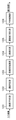
図8は、第2実施形態の画像形成部において、形成対象となる入力画像に基づき、露光制御信号を生成するまでの画像処理を行うための構成例を示すブロック図である。同図に示す構成は専用ハードウェアによって実現することも可能であり、また、ソフトウェアによって実現することも可能である。 FIG. 8 is a block diagram illustrating a configuration example for performing image processing until an exposure control signal is generated based on an input image to be formed in the image forming unit of the second embodiment. The configuration shown in the figure can be realized by dedicated hardware, or can be realized by software.
図8において、801は2画素平均化部であり、802は多値誤差拡散部、803は2画素化部、806はPWM変換部である。そして、上述した第1実施形態における濃度値入れ替え部104に変えて、2画素化部803が2つのLUT804,805を有する。以下、上述した第1実施形態の画像形成部と異なる構成についてのみ、説明する。
In FIG. 8, 801 is a two-pixel averaging unit, 802 is a multi-value error diffusion unit, 803 is a two-pixel conversion unit, and 806 is a PWM conversion unit. Then, instead of the density
2画素化部803は、多値誤差拡散部802より出力された1画素分の量子化代表値を、副走査方向に上下2画素分の濃度値に変換する際に、2種類のLUT804,805のいずれかを参照する。LUT804,805はすなわち、入力される1画素分の量子化代表値に対して、出力すべき上下2画素分の濃度値とを組として、それぞれ複数組を保持している。例えば、多値誤差拡散部802において9値の誤差拡散処理を行う場合、LUT804,805はそれぞれ以下のような値を有する。例えばLUT804として、副走査方向の上側に相当する画素の方が大きな濃度値を有するような組を9個有し、LUT805として、副走査方向の下側に相当する画素の方が大きな濃度値を有するような組を9個有する。この場合、LUT804,805は2画素化処理用に計18個の変換値を有していることになる。もちろん、LUT804が下側画素を高濃度とする値を有し、LUT805が下側画素を高濃度とする値を有しても良いし、また、LUT804,805を1つのLUTとして構成することも可能である。
The two-
第2実施形態においては、2画素化部803に対しての入力画像の2画素化の際に参照するLUTを主走査方向に対して2画素毎、副走査方向に対して1画素毎に切り替えることによって、第1実施形態のような濃度値入れ替え処理を不要としている。
In the second embodiment, the LUT that is referred to when the input image to the two-
特に、LUT804とLUT805を1つのRAM上に構成した場合は、以下のような制御が可能である。すなわち、主走査方向のカウンタXのLSBから2ビット目のデータと副走査方向のカウンタYのLSBから1ビット目のデータをEXORした値を、LUTを構成するRAMのアドレス線の1ビットに使用する。これだけで、濃度値入れ替え後の出力画素値を得ることができる。
In particular, when the
図9に、第2実施形態における画像処理の流れを示す。第2実施形態では、入力される画像データの全プレーンに対し、図9に示す画像処理を施す。 FIG. 9 shows the flow of image processing in the second embodiment. In the second embodiment, the image processing shown in FIG. 9 is performed on all planes of input image data.
まずステップS901,S902において、上述した第1実施形態と同様に、2画素平均化処理,多値誤差拡散処理をそれぞれ行う。 First, in steps S901 and S902, a two-pixel averaging process and a multi-level error diffusion process are performed, respectively, as in the first embodiment described above.
次にステップS903において、多値誤差拡散処理の出力画像に対し、2画素化処理A、または2画素化処理Bのいずれを実施するかを判断する。この判断はすなわち、主走査方向における2画素毎、及び副走査方向における1画素毎に、参照LUTを切り替えることができればよい。ここでは、副走査方向のアドレスyの奇遇、および主走査方向のアドレスxの位置によって、以下のように参照するLUTを切り替える。 Next, in step S903, it is determined whether the 2-pixel conversion process A or the 2-pixel conversion process B is performed on the output image of the multilevel error diffusion process. That is, it is only necessary to switch the reference LUT every two pixels in the main scanning direction and every pixel in the sub scanning direction. Here, the LUT to be referred to is switched as follows depending on the odd address y in the sub-scanning direction and the position of the address x in the main scanning direction.
例えば、副走査アドレスyが奇数である場合、主走査方向のアドレスxを4で除算した余りが0または1であれば、2画素化の際に副走査方向の上側相当の画素を高濃度とするために、ステップS904でLUT804を参照した2画素化処理Aを行う。一方、余りが2または3であれば、2画素化の際に副走査方向の下側相当の画素を高濃度とするために、ステップS905でLUT805を参照した2画素化処理Bを行う。また、次のライン、すなわち副走査アドレスyが偶数である場合には、主走査方向のアドレスxを4で除算した余りが0または1であればステップS905でLUT805を参照した2画素化処理Bを行う。一方、余りが2または3であればステップS904でLUT804を参照した2画素化処理Aを行う。
For example, when the sub-scanning address y is an odd number, if the remainder obtained by dividing the address x in the main scanning direction by 4 is 0 or 1, the pixel corresponding to the upper side in the sub-scanning direction is set to a high density when two pixels are formed. In order to do this, a two-pixel conversion process A referring to the
これにより、上述した第1実施形態において濃度値入れ替え処理を行った場合と同様に、2×2画素ブロック単位で市松状に、濃ブロックと淡ブロックが生成される。なお、上述したように、ここでの判断結果と選択対象となる2画素化処理との組み合わせはこの例に限定されず、逆であっても良い。 Accordingly, as in the case where the density value replacement process is performed in the first embodiment described above, dark blocks and light blocks are generated in a checkered pattern in units of 2 × 2 pixel blocks. As described above, the combination of the determination result here and the two-pixel conversion process to be selected is not limited to this example, and may be reversed.
ステップS904またはS905のいずれかで2画素化処理が施された出力データは、ステップS906で露光用のPWM信号に変換され、プリンタエンジンに出力される。そして、上記の一連の処理が完了すると、ステップS907にて一連の処理を続行するか否かが判定され、続行する場合にはステップS901に戻って一連の処理を繰り返す。 The output data that has been subjected to the two-pixel process in either step S904 or S905 is converted into an exposure PWM signal in step S906 and output to the printer engine. When the series of processes is completed, it is determined in step S907 whether or not to continue the series of processes. If so, the process returns to step S901 and the series of processes is repeated.
以上説明したように第2実施形態によれば、量子化後の画素の主走査位置に応じて、2画素化処理の際に参照するLUTを切り替えることによって、上述した第1実施形態と同様の効果を得ることができる。 As described above, according to the second embodiment, the same LUT as that of the above-described first embodiment is performed by switching the LUT that is referred to in the two-pixel conversion process according to the main scanning position of the pixel after quantization. An effect can be obtained.
<第3実施形態>
以下、本発明に係る第3実施形態について説明する。なお、第3実施形態も上述した第1実施形態で図14に示したような構成からなる、4ドラム方式のカラーレーザビームプリンタにおいて実現される。
<Third Embodiment>
The third embodiment according to the present invention will be described below. The third embodiment is also realized in a four-drum type color laser beam printer having the configuration shown in FIG. 14 in the first embodiment described above.
図10は、第3実施形態の画像形成部において、形成対象となる入力画像に基づき、露光制御信号を生成するまでの画像処理を行うための構成例を示すブロック図である。同図に示す構成は専用ハードウェアによって実現することも可能であり、また、ソフトウェアによって実現することも可能である。 FIG. 10 is a block diagram illustrating a configuration example for performing image processing until an exposure control signal is generated based on an input image to be formed in the image forming unit of the third embodiment. The configuration shown in the figure can be realized by dedicated hardware, or can be realized by software.
図10において、2画素平均化部1001,多値誤差拡散部1002,2画素化部1003,濃度値入れ替え部1004,PWM変換部1005は、入力画像におけるKプレーン用の構成である。また、2画素平均化部1006,多値誤差拡散部1007,2画素化部1008,PWM変換部1009は、入力画像におけるCMYプレーン用の構成である。すなわち第3実施形態においては、入力画像のKプレーンと他のCMYプレーンとで処理部が異なり、CMYプレーンに対しては濃度値入れ替え部を不要とすることを特徴とする。
In FIG. 10, a two-
一般に、K色における粒状性は他の色と比較して顕著である。そこで本実施形態では特にKプレーンを特定プレーンとして、上述した第1実施形態で示した構成により、粒状性をより改善するような処理を施すとする。一方、特定プレーン以外のCMYプレーンについては、2画素化部1008から出力される2画素の濃度値の差を、2画素化部1003によるKプレーンの濃度値の差以下とし、濃度値入れ替え処理を行わない。このような構成によれば、粒状感の顕著なK色についてはその粒状性を改善し、他色に対しては処理負荷をより小さくして、高速な擬似中間調処理を実行することができる。また、プレーン間の相対的なズレ(レジズレ)による色モアレの発生を抑制することができる。
In general, the graininess in the K color is remarkable as compared with other colors. Therefore, in the present embodiment, it is assumed that the K plane is a specific plane, and processing that further improves the graininess is performed by the configuration described in the first embodiment. On the other hand, for the CMY planes other than the specific plane, the density value difference between the two pixels output from the two-
図11に、第3実施形態における画像処理の流れを示す。第3実施形態では、入力される画像データの全プレーンに対し、図11に示す画像処理を施す。 FIG. 11 shows the flow of image processing in the third embodiment. In the third embodiment, the image processing shown in FIG. 11 is performed on all planes of input image data.
まずステップS1101,S1102において、上述した第1実施形態と同様に、2画素平均化処理,多値誤差拡散処理をそれぞれ行う。 First, in steps S1101 and S1102, a two-pixel averaging process and a multi-value error diffusion process are performed, respectively, as in the first embodiment described above.
次にステップS1103において、多値誤差拡散後の画像のプレーンがKである場合には、ステップS1104で第1実施形態と同様の2画素化処理(2画素化処理A)を行う。そしてさらにステップS1106で、上述した第1実施形態と同様の濃度値入れ替え処理が施される。 Next, in step S1103, if the image plane after multilevel error diffusion is K, in step S1104, the two-pixel processing (two-pixel processing A) similar to that of the first embodiment is performed. In step S1106, density value replacement processing similar to that in the first embodiment described above is performed.
一方、多値誤差拡散後の画像がK以外のCMYプレーンである場合には、ステップS1105で2画素化処理Bを行う。この2画素化処理Bとしては、上述したように、置き換え対象となる2画素間の差分が、ステップS1004の2画素化処理Aでの差分以下となるように制御される。すなわち、2画素化処理Aと2画素化処理Bとでは、置き換え対象の画素値の組において、2画素間の差が上記条件を満たすように、予め設定されている。 On the other hand, if the image after multilevel error diffusion is a CMY plane other than K, a two-pixel process B is performed in step S1105. As described above, the two-pixel conversion process B is controlled so that the difference between the two pixels to be replaced is equal to or less than the difference in the two-pixel conversion process A in step S1004. That is, in the two-pixel processing A and the two-pixel processing B, the difference between the two pixels is set in advance so as to satisfy the above condition in the set of pixel values to be replaced.
ステップS1106による濃度値入れ替え処理、またはステップS1105による2画素化処理Bが施された出力データは、ステップS1107で露光用のPWM信号に変換され、プリンタエンジンに出力される。そして、上記の一連の処理が完了すると、ステップS1108にて一連の処理を続行するか否かが判定され、続行する場合にはステップS1101に戻って一連の処理を繰り返す。 The output data that has been subjected to the density value replacement process in step S1106 or the two-pixel process B in step S1105 is converted into an exposure PWM signal in step S1107 and output to the printer engine. When the series of processes is completed, it is determined in step S1108 whether or not to continue the series of processes. If so, the process returns to step S1101 to repeat the series of processes.
なお、第3実施形態ではKプレーンとCMYプレーンとで全ての処理部が異なる例を示したが、例えば2画素平均化部や多値誤差拡散部、PWM変換部等、各プレーンに対して同様の処理を施す構成は共通としても良い。この場合すなわち、第1の2画素化部としての2画素化部1003と、第2の2画素化部としての2画素化部1008、および濃度値入れ替え部1004については、色プレーンに応じて用いられるが、他の構成については全て共通となる。また、2画素化部を共通とし、該2画素化部内でプレーンに応じて処理を切り替えるようにしても良い。
In the third embodiment, an example in which all the processing units are different between the K plane and the CMY plane is shown. However, the same applies to each plane such as a two-pixel averaging unit, a multilevel error diffusion unit, and a PWM conversion unit. The configuration for performing the process may be common. In this case, that is, the two-
また、第3実施形態では入力画像がCMYKのプレーンを有し、Kプレーンに対してのみ濃度入れ替え処理を行う例を説明したが、本発明はもちろんこの例に限定されない。他の成分構成からなる画像データであっても、特に粒状性が顕著となる特定プレーンまたはプレーンの組み合わせに対してのみ、濃度値入れ替え処理を行うようにしても良い。 In the third embodiment, the input image has a CMYK plane, and the density replacement process is performed only on the K plane. However, the present invention is not limited to this example. Even for image data having other component configurations, density value replacement processing may be performed only for a specific plane or a combination of planes in which graininess is particularly significant.
以上説明したように第3実施形態によれば、粒状性の顕著なKプレーンに対してのみ、濃度値入れ替え処理を行うことにより、上述した第1実施形態と同様に粒状性を改善しつつ、他の色プレーンについては高速処理が実現される。 As described above, according to the third embodiment, by performing the density value replacement process only for the K-plane with remarkable graininess, the graininess is improved as in the first embodiment described above. High-speed processing is realized for the other color planes.
<第4実施形態>
以下、本発明に係る第4実施形態について説明する。なお、第4実施形態も上述した第1実施形態で図14に示したような構成からなる、4ドラム方式のカラーレーザビームプリンタにおいて実現される。
<Fourth embodiment>
The fourth embodiment according to the present invention will be described below. The fourth embodiment is also realized in a four-drum type color laser beam printer having the configuration shown in FIG. 14 in the first embodiment described above.
図12は、第4実施形態の画像形成部において、形成対象となる入力画像に基づき、露光制御信号を生成するまでの画像処理を行うための構成例を示すブロック図である。同図に示す構成は専用ハードウェアによって実現することも可能であり、また、ソフトウェアによって実現することも可能である。 FIG. 12 is a block diagram illustrating a configuration example for performing image processing until an exposure control signal is generated based on an input image to be formed in the image forming unit of the fourth embodiment. The configuration shown in the figure can be realized by dedicated hardware, or can be realized by software.
図12において、1201は2画素平均化部であり、1202は濃度判定部、1203は多値誤差拡散部、1204は2画素化部、1205は濃度値入れ替え部、1206はPWM変換部である。第4実施形態においてはすなわち、濃度判定部1202を備えることを特徴とし、以下、上述した第1実施形態の画像形成部と異なる構成についてのみ、説明する。
In FIG. 12,
第4実施形態では、濃度判定部1202において、入力画像の濃度値に応じて処理を切り替えることを特徴とする。例えば、0〜255の256階調をとりうる画像データを入力し、128〜255までの値であれば、2画素化部1204から出力される2画素間の差分(濃度差)を小さくして、濃度値入れ替え部1206における濃度値入れ替え処理を行わないように制御する。一方、0〜128の値であれば、2画素化部1204からの出力される2画素間の濃度差を大きくし、濃度値入れ替え部1206における濃度値入れ替え処理を行うように制御する。これにより、粒状感の目立つハイライト部(高濃度部)に対しては第1実施形態と同様に粒状感を改善することができる。
The fourth embodiment is characterized in that the
このように第4実施形態においては、濃度判定部1202における濃度値の判定結果に応じて、2画素化部1204および濃度値入れ替え部1205における処理を切り替える。この切り替え制御は例えば、濃度判定結果に応じて所定のフラグをセットすることにより行われる。
As described above, in the fourth embodiment, the processing in the two-
図13に、第4実施形態における画像処理の流れを示す。第4実施形態では、入力される画像データの全プレーンに対し、図13に示す画像処理を施す。 FIG. 13 shows the flow of image processing in the fourth embodiment. In the fourth embodiment, the image processing shown in FIG. 13 is performed on all planes of input image data.
まずステップS1301,S1302において、上述した第1実施形態と同様に、2画素平均化処理,多値誤差拡散処理をそれぞれ行う。 First, in steps S1301 and S1302, a two-pixel averaging process and a multi-level error diffusion process are performed as in the first embodiment described above.
次にステップS1303において、多値誤差拡散後の画素値を予め設定した閾値TH(上記例であればTH=128)と比較する。画素値が閾値THよりも小さい場合は、ステップS1304で上述した高濃度部に対する2画素化処理Aを行い、さらにステップS1306で上述した第1実施形態と同様の濃度値入れ替え処理が施される。一方、画素値が閾値TH以上である場合は、ステップS1305で上述した低濃度部に対する2画素化処理Bを行う。 In step S1303, the pixel value after multi-level error diffusion is compared with a preset threshold value TH (TH = 128 in the above example). If the pixel value is smaller than the threshold value TH, the two-pixel process A for the high density portion described above is performed in step S1304, and the density value replacement process similar to that of the first embodiment described above is performed in step S1306. On the other hand, if the pixel value is greater than or equal to the threshold value TH, the two-pixel process B for the low density portion described above is performed in step S1305.
ステップS1306による濃度値入れ替え処理、またはステップS1305による2画素化処理Bが施された出力データは、ステップS1307で露光用のPWM信号に変換され、プリンタエンジンに出力される。そして、上記の一連の処理が完了すると、ステップS1308にて一連の処理を続行するか否かが判定され、続行する場合にはステップS1301に戻って一連の処理を繰り返す。 The output data that has been subjected to the density value replacement processing in step S1306 or the two-pixel processing B in step S1305 is converted into an exposure PWM signal in step S1307 and output to the printer engine. When the series of processes described above is completed, it is determined in step S1308 whether or not to continue the series of processes. If so, the process returns to step S1301 and the series of processes is repeated.
以上説明した様に第4実施形態によれば、入力画像の濃度値に応じて、2画素化処理および濃度値入れ替え処理を行う。これにより、例えば特に低濃度部に対しては上述した第1実施形態と同様に粒状性を改善しつつ、高濃度部に対しては高速処理が実現される。 As described above, according to the fourth embodiment, the two-pixel process and the density value replacement process are performed according to the density value of the input image. Thereby, for example, high-speed processing is realized for the high density portion while improving the graininess as in the first embodiment described above, particularly for the low density portion.
なお、上記説明では入力値に応じて2画素化処理方法を切り替える構成としたが、これに限らず、例えば、2つの2画素化処理を同時に行い、2つの2画素化処理の出力をブレンドして出力濃度値とする構成としても良い。この場合、入力濃度値に応じて2つの2画素化処理出力のブレンド比率を変更するようにしても良い。このような構成によれば、入力濃度に応じて2つの出力画素の濃度差が徐々に切り替わるため、切り替え部分が検知されにくくなる。また、閾値を複数設けて3つ以上の2画素化処理方法を切り替えるようにしても良い。 In the above description, the two-pixel conversion processing method is switched according to the input value. However, the present invention is not limited to this. For example, two two-pixel conversion processes are performed simultaneously, and the outputs of the two two-pixel conversion processes are blended. The output density value may be used. In this case, the blend ratio of the two 2-pixel processing outputs may be changed according to the input density value. According to such a configuration, the density difference between the two output pixels is gradually switched according to the input density, so that the switching portion is hardly detected. A plurality of threshold values may be provided to switch between three or more two-pixel processing methods.
<第5実施形態>
以下、本発明に係る第5実施形態について説明する。なお、第5実施形態も上述した第1の実施形態で図14に示したような構成からなる、4ドラム方式カラーレーザービームプリンタにおいて実現される。
<Fifth Embodiment>
The fifth embodiment according to the present invention will be described below. The fifth embodiment is also realized in a four-drum color laser beam printer having the configuration shown in FIG. 14 in the first embodiment described above.
図15は、第5実施形態の画像形成部において、形成対象となる入力画像に基づき、露光制御信号を生成するまでの画像処理を行うための構成例を示すブロック図である。同図に示す構成は専用ハードウェアによって実現することも可能であり、また、ソフトウェアによって実現することも可能である。 FIG. 15 is a block diagram illustrating a configuration example for performing image processing until an exposure control signal is generated based on an input image to be formed in the image forming unit of the fifth embodiment. The configuration shown in the figure can be realized by dedicated hardware, or can be realized by software.
図15において、1501は2画素平均化部であり、1502は多値誤差拡散部、1503は2画素化部、1504は濃度値入れ替え部、1505はスクリーン角生成部、1506はPWM変換部である。第5実施形態においてはすなわち、スクリーン角生成部1505を備えることを特徴とし、以下、上述した第1実施形態の画像形成部と異なる構成のみ、説明する。
In FIG. 15,
第5実施形態では、スクリーン角生成部S1506において、出力画像がスクリーン角を持つように濃度値を入れ替える処理を行う。そしてさらに、入力される画像のプレーン毎に生成スクリーンを変更する。これにより、色モアレを抑えつつ第1実施形態と同様に粒状感を改善することができる。 In the fifth embodiment, the screen angle generation unit S1506 performs a process of changing density values so that the output image has a screen angle. Further, the generation screen is changed for each plane of the input image. Thereby, the graininess can be improved as in the first embodiment while suppressing color moire.
図16に、第5実施形態における画像処理の流れを示す。第5実施形態では、入力される画像データの全プレーンに対し、図16に示す画像処理を施す。 FIG. 16 shows the flow of image processing in the fifth embodiment. In the fifth embodiment, the image processing shown in FIG. 16 is performed on all planes of input image data.
まずステップS1601,S1602,S1603において、上述した第1実施形態と同様に、2画素平均化処理,多値誤差拡散処理、2画素化処理をそれぞれ行う。 First, in steps S1601, S1602, and S1603, a two-pixel averaging process, a multi-value error diffusion process, and a two-pixel process are performed, respectively, as in the first embodiment described above.
次にステップS1604において、濃度入れ替え処理を行うか否か判断する。ここで、濃度入れ替え処理の判断方法について、図17A〜図17Fを用いて説明する。 In step S1604, it is determined whether or not to perform density replacement processing. Here, the determination method of the density replacement process will be described with reference to FIGS. 17A to 17F.
図17Aに、ステップS1603の2画素化処理による出力値例を示す。なお、第5実施形態の2画素化部1503においては、多値誤差拡散部1502からの出力値が0(白)であった場合、その2画素化結果として、少なくとも1画素の濃度値として0以外の値を出力する。
FIG. 17A shows an example of output values obtained by the two-pixel process in step S1603. In the two-
図17Bは、濃度入れ替え処理を実施する画素の例を示す。図17Cは、濃度入れ替え処理後の出力例を示す。この例では、2画素化部1503からの2画素化出力に対し、スクリーン角生成部1505の配置変更テーブルを用いて、濃度入れ替え処理を実施する。すなわち、図17Aに示す入力画像に対し、配置変更テーブルを参照して、図17Bの矢印で示された画素同士を入れ替える。このような濃度入れ替え処理によって、図17Cに示す様にスクリーン角を付すことができる。このとき、配置変更テーブルのサイズ及び配置パターンを変更することによって、多様なスクリーン角を設定することができる。
FIG. 17B shows an example of a pixel that performs density replacement processing. FIG. 17C shows an output example after the density replacement process. In this example, density replacement processing is performed on the 2-pixel output from the 2-
次に、上述した濃度入れ替え部1504におけるスクリーン生成の動作について、具体的に説明する。
Next, the screen generation operation in the above-described
2画素化部1503からは、副走査方向に2画素づつが出力される。これを主走査方向に2画素ずつ束ねることにより、2×2のブロックを作る。この2×2ブロックの濃淡画素を入れ替えてできるパターンとしては、図17Dに示す1700〜1705の6種類がある。但し、1700は入れ替えなしのパターンである。また、1700〜1705にはそれぞれ、選択番号が0〜5が付されている。これらの入れ替えパターンをテーブル化することで、多様なスクリーン角を生成することができる。
From the two-
図17Eに、図17Cのスクリーン角を生成する場合における、配置変更テーブルの設定例を示す。図17Eにおいて、各数字は入れ替えパターンの選択番号を示し、すなわち「0」は図17Dの1700、「1」は1701、「2」は1702、「3」は1703、の各パターンを選択することを示す。つまり、配置変更テーブルに(1,0,2,3)の4つの値を格納しておき、この値を順番に読み出し、各値に対応するパターンを選択するシーケンスを繰り返すことで、スクリーン各が生成される。 FIG. 17E shows a setting example of the arrangement change table when the screen angle of FIG. 17C is generated. In FIG. 17E, each number indicates a replacement pattern selection number, that is, “0” selects 1700 in FIG. 17D, “1” 1701, “2” 1702, and “3” 1703. Indicates. That is, by storing four values (1, 0, 2, 3) in the arrangement change table, reading these values in order, and repeating a sequence for selecting a pattern corresponding to each value, Generated.
なお、次のラインの処理においては、配置変更テーブルの対応位置を1つ右にずらせば良い。このように、1ライン処理が進む毎に対応位置を1つ右にずらし、濃度入れ替え処理を行う。なお、配置変更テーブルの1ライン処理が進む毎に対応位置を2つ(あるいは3つ)右にずらせば、異なるスクリーン角が実現される。同様に、読み出し順を(3,0,2,1)の順にしても、スクリーン角は異なる。つまり、(1,0,2,3)の4つの値の順序(但し、ドットを集中させるため、(2,1)の順序は固定とする)で6種類のスクリーンを実現できる。 In the processing of the next line, the corresponding position in the arrangement change table may be shifted to the right by one. In this way, each time one-line processing proceeds, the corresponding position is shifted to the right by one, and density replacement processing is performed. If the corresponding position is shifted to the right by two (or three) each time one-line processing of the arrangement change table proceeds, different screen angles are realized. Similarly, even if the reading order is (3, 0, 2, 1), the screen angles are different. That is, six types of screens can be realized in the order of four values (1, 0, 2, 3) (however, the order of (2, 1) is fixed in order to concentrate dots).
図17Fは、さらに図17の1704、1705のパターンを用いて異なるスクリーンを実現する例を示している。この例では、3×2の配置変更テーブルを用いている。つまり、1ライン処理が進む毎に(3,5,0)と(0,4,3)のパターンを交代して使用している。
FIG. 17F shows an example in which different screens are realized using the
上述したように、ステップS1604で濃度入れ替えを行うと判断した場合には、ステップS1605にて、2画素化後の画像に対して上述したような濃度入れ替え処理を行った後、ステップS1606に進む。一方、濃度入れ替えを行わないと判断した場合には、そのままステップS1606に進む。 As described above, if it is determined in step S1604 that density replacement is to be performed, in step S1605, the density replacement processing as described above is performed on the image after conversion to two pixels, and then the process proceeds to step S1606. On the other hand, if it is determined not to change the density, the process directly proceeds to step S1606.
ステップS1605による濃度入れ替え処理、またはステップS1603による2画素化処理が施された出力データは、ステップS1606で露光用のPWM信号に変換され、プリンタエンジンに出力される。そして、上記の一連の処理が完了すると、ステップS1607にて一連の処理を続行するか否かが判定され、続行する場合にはステップS1601に戻って一連の処理を繰り返す。 The output data that has been subjected to the density switching process in step S1605 or the two-pixel process in step S1603 is converted into an exposure PWM signal in step S1606 and output to the printer engine. When the series of processes described above is completed, it is determined in step S1607 whether or not to continue the series of processes. If so, the process returns to step S1601 to repeat the series of processes.
以上説明した様に第5実施形態によれば、スクリーン角を持つように濃度入れ替え処理を行うことにより、色モアレを抑えつつ、上述した第1実施形態と同様に粒状性を改善することができる。 As described above, according to the fifth embodiment, by performing the density switching process so as to have a screen angle, it is possible to improve the graininess as in the first embodiment described above while suppressing color moire. .
なお、第5実施形態においては、配置変換テーブルとして図17E,図17Fに示すような4×4,4×2のテーブルを示した。しかしながら配置変換テーブルはこのサイズに限らず、M×Nサイズ(M,Nは共に1以上で、いずれか一方は2以上の整数)であれば適用可能である。 In the fifth embodiment, 4 × 4 and 4 × 2 tables as shown in FIGS. 17E and 17F are shown as the arrangement conversion table. However, the arrangement conversion table is not limited to this size, and is applicable to an M × N size (M and N are both 1 or more and one of them is an integer of 2 or more).
<第6実施形態>
以下、本発明に係る第6実施形態について説明する。なお、第6実施形態も上述した第1の実施形態で図14に示したような構成からなる、4ドラム方式カラーレーザービームプリンタにおいて実現される。
<Sixth Embodiment>
The sixth embodiment according to the present invention will be described below. The sixth embodiment is also realized in a four-drum color laser beam printer having the configuration shown in FIG. 14 in the first embodiment described above.
図18は、第6実施形態の画像形成部において、形成対象となる入力画像に基づき、露光制御信号を生成するまでの画像処理を行うための構成例を示すブロック図である。同図に示す構成は専用ハードウェアによって実現することも可能であり、また、ソフトウェアによって実現することも可能である。 FIG. 18 is a block diagram illustrating a configuration example for performing image processing until an exposure control signal is generated based on an input image to be formed in the image forming unit of the sixth embodiment. The configuration shown in the figure can be realized by dedicated hardware, or can be realized by software.
図18において、1801は2画素平均化部であり、1802は多値誤差拡散部、1803は2画素化部、1805はスクリーン生成部、1806はPWM変換部である。上述した第5実施形態においては、濃度値入れ替え部1504でスクリーン角生成を行う例を示したが、第6実施形態においては、2画素化部1803でスクリーン角を生成することにより、濃度値入れ替え部を不要としたことを特徴とする。以下、上述した第1実施形態の画像形成部と異なる構成のみ、説明する。
In FIG. 18,
図19に、第6実施形態における画像処理の流れを示す。第6実施形態では、入力される画像データの全プレーンに対し、図19に示す画像処理を施す。 FIG. 19 shows the flow of image processing in the sixth embodiment. In the sixth embodiment, the image processing shown in FIG. 19 is performed on all planes of input image data.
まずステップS1901,S1902において、上述した第1実施形態と同様に、2画素平均化処理,多値誤差拡散処理をそれぞれ行う。 First, in steps S1901 and S1902, a two-pixel averaging process and a multi-value error diffusion process are performed, respectively, as in the first embodiment described above.
次にステップS1903,S1904において、ステップS1902で多値誤差拡散処理された画像に対し、複数の画素値テーブル(以下、単にLUTと称する)のいずれかを参照して2画素化処理を施す。そのためにまずステップS1903において、複数のLUTのうち一つを選択する。ここで図20を用いて、LUTの選択方法について説明する。 Next, in steps S1903 and S1904, the image subjected to the multilevel error diffusion process in step S1902 is subjected to a two-pixel conversion process with reference to one of a plurality of pixel value tables (hereinafter simply referred to as LUT). For this purpose, first, in step S1903, one of the plurality of LUTs is selected. Here, the LUT selection method will be described with reference to FIG.
第6実施形態では、2画素化部1803の出力に対して8×4のテーブルを用いてスクリーンを設定する。例えば、スクリーン角生成部1805が、互いに異なる4つのLUTを有し、上記8×4のテーブルの値により該4つのLUTのいずれか1つを選択してスクリーンを設定する。図20Aに、これら4つのLUTの例を示す。なお図20Aにおいて、各LUT2001〜2004には選択番号「0」〜「4」が付されており、各LUTは選択番号ごとに、以下のように構成されている。
In the sixth embodiment, the screen is set using an 8 × 4 table for the output of the two-
1.上の画素が濃いLUT
2.選択番号1のLUTの上下の画素値が入れ替わっているLUT
3.2画素が選択番号1のLUTの薄い画素のみで構成されているLUT
4.2画素が選択番号1のLUTの濃い画素のみで構成されているLUT
次に、これらLUTの選択方法について説明する。
1. LUT with darker pixels
2. LUT in which the pixel values above and below the LUT of
3.2 LUT in which 2 pixels are composed only of thin pixels with
4.2 An LUT in which 2 pixels are composed only of dark pixels of
Next, a method for selecting these LUTs will be described.
図20Bは、2画素平均化後の画像の各画素に対し、上記4つのLUTから選択すべきLUTの番号を表す、テーブル選択用の8×4の選択テーブルである。すなわち第6実施形態では2画素化部1803において、まずステップS1903で図20Bに従って参照するLUTを画素ごとに変更する。そしてステップS1904で該選択されたLUTに従った2画素化を行うことにより、図20Cに示すような2画素化出力を得ることができる。すなわち、2画素化の時点でスクリーン角を持たせるような濃度入れ替え処理を同時に実行することができる。
FIG. 20B is an 8 × 4 selection table for table selection that represents the number of the LUT to be selected from the above four LUTs for each pixel of the image after the two-pixel averaging. That is, in the sixth embodiment, the two-
第6実施形態では、図20Bに示す選択テーブルのサイズ及び格納されるLUTの選択番号を変更することによって、多様なスクリーン角を実現することができる。従って、色プレーン毎に選択テーブルを変えることで、色プレーン毎にスクリーン角を変更することが可能となる。 In the sixth embodiment, various screen angles can be realized by changing the size of the selection table shown in FIG. 20B and the selection number of the stored LUT. Therefore, the screen angle can be changed for each color plane by changing the selection table for each color plane.
なお、ここでは4つのLUTを選択する例を示したが、本発明はこの例に限らず、1つのLUTから4つのパターンを生成するようにしても良い。例えば2画素化の際に、上記選択番号1のLUTの上下を入れ替えて選択番号2の出力とし、選択番号1のLUTの下の画素値を選択番号3の出力とし、選択番号1のLUTの上の画素値を選択番号4の出力とすれば良い。
Although an example in which four LUTs are selected is shown here, the present invention is not limited to this example, and four patterns may be generated from one LUT. For example, when the number of pixels is changed to 2, the LUT with the
また、図20Bに示す8×4の選択テーブルは、(4,3,1,1,2,2,3,4)のパターンについて、ラインの変更ごとにその開始位置を右方向に2画素づつずらしたパターンになっていることが分かる。従って、例えば8×1の選択テーブルのみを格納しておき、ラインの先頭で選択テーブルの読み出し位置を2画素分右にシフトさせるようにしても良い。 In addition, the 8 × 4 selection table shown in FIG. 20B indicates that the start position of the pattern (4, 3, 1, 1, 2, 2, 3, 4) is 2 pixels in the right direction for each line change. It can be seen that the pattern is shifted. Therefore, for example, only the 8 × 1 selection table may be stored, and the reading position of the selection table may be shifted to the right by two pixels at the beginning of the line.
以上のように、2画素化部1803においてスクリーン角が生成された出力データは、ステップS1905で露光用のPWM信号に変換され、プリンタエンジンに出力される。そして、上記の一連の処理が完了すると、ステップS1906にて一連の処理を続行するか否かが判定され、続行する場合にはステップS1901に戻って一連の処理を繰り返す。
As described above, the output data in which the screen angle is generated in the two-
以上説明した様に第6実施形態によれば、2値化処理の際にスクリーン角を持つような濃度入れ替えを行うことにより、色モアレを抑えつつ、上述した第1実施形態と同様に粒状性を改善することができる。 As described above, according to the sixth embodiment, the density is changed so as to have a screen angle during the binarization process, thereby suppressing the color moire and the graininess as in the first embodiment described above. Can be improved.
なお、第6実施形態においては、選択テーブルとして図20Bに示すような8×4のテーブルを示した。しかしながら選択テーブルはこのサイズに限らず、M×Nサイズ(M,Nは共に1以上で、いずれか一方は2以上の整数)であれば適用可能である。 In the sixth embodiment, an 8 × 4 table as shown in FIG. 20B is shown as the selection table. However, the selection table is not limited to this size, and can be applied to any size of M × N (M and N are both 1 or more and one of them is an integer of 2 or more).
なお、上述した第1〜第6実施形態においては、入力画像を2画素平均化し、多値誤差拡散の後に2画素化する例を示したが、本発明はこのような2画素単位に限らず、H画素単位(Hは2以上の自然数)によるH画素平均化およびH画素化処理を行っても良い。すなわち、入力画像の副走査方向にH画素を平均化することによって、副走査方向のサイズを1/Hに縮小した後、多値誤差拡散処理を施し、その後、H画素化すれば良い。 In the first to sixth embodiments described above, an example in which an input image is averaged by two pixels and converted to two pixels after multilevel error diffusion has been shown, but the present invention is not limited to such a two-pixel unit. H pixel averaging and H pixel processing in units of H pixels (H is a natural number of 2 or more) may be performed. That is, by averaging H pixels in the sub-scanning direction of the input image to reduce the size in the sub-scanning direction to 1 / H, multi-value error diffusion processing is performed, and then H pixels are formed.
<他の実施形態>
本発明は例えば、システム、装置、方法、プログラム若しくは記憶媒体(記録媒体)等としての実施態様をとることが可能である。具体的には、複数の機器(例えば、ホストコンピュータ、インタフェース機器、撮影装置、webアプリケーション等)から構成されるシステムに適用しても良いし、また、一つの機器からなる装置に適用しても良い。
<Other embodiments>
The present invention can take the form of, for example, a system, apparatus, method, program, or storage medium (recording medium). Specifically, the present invention may be applied to a system composed of a plurality of devices (for example, a host computer, an interface device, a photographing device, a web application, etc.), or may be applied to a device composed of one device. good.
本発明は、前述した実施形態の機能を実現するソフトウェアのプログラムを、システムあるいは装置に直接あるいは遠隔から供給し、そのシステムあるいは装置のコンピュータが該供給されたプログラムコードを読み出して実行することによっても達成される。なお、この場合のプログラムとは、実施形態において図に示したフローチャートに対応したコンピュータ可読のプログラムである。 The present invention also provides a software program that implements the functions of the above-described embodiments directly or remotely to a system or apparatus, and the system or apparatus computer reads out and executes the supplied program code. Achieved. The program in this case is a computer-readable program corresponding to the flowchart shown in the drawing in the embodiment.
従って、本発明の機能処理をコンピュータで実現するために、該コンピュータにインストールされるプログラムコード自体も本発明を実現するものである。つまり、本発明は、本発明の機能処理を実現するためのコンピュータプログラム自体も含まれる。 Accordingly, since the functions of the present invention are implemented by computer, the program code installed in the computer also implements the present invention. In other words, the present invention includes a computer program itself for realizing the functional processing of the present invention.
その場合、プログラムの機能を有していれば、オブジェクトコード、インタプリタにより実行されるプログラム、OSに供給するスクリプトデータ等の形態であっても良い。 In that case, as long as it has the function of a program, it may be in the form of object code, a program executed by an interpreter, script data supplied to the OS, or the like.
プログラムを供給するための記録媒体としては、以下に示す媒体がある。例えば、フロッピー(登録商標)ディスク、ハードディスク、光ディスク、光磁気ディスク、MO、CD-ROM、CD-R、CD-RW、磁気テープ、不揮発性のメモリカード、ROM、DVD(DVD-ROM,DVD-R)などである。 Recording media for supplying the program include the following media. For example, floppy disk, hard disk, optical disk, magneto-optical disk, MO, CD-ROM, CD-R, CD-RW, magnetic tape, nonvolatile memory card, ROM, DVD (DVD-ROM, DVD- R).
プログラムの供給方法としては、以下に示す方法も可能である。すなわち、クライアントコンピュータのブラウザからインターネットのホームページに接続し、そこから本発明のコンピュータプログラムそのもの(又は圧縮され自動インストール機能を含むファイル)をハードディスク等の記録媒体にダウンロードする。また、本発明のプログラムを構成するプログラムコードを複数のファイルに分割し、それぞれのファイルを異なるホームページからダウンロードすることによっても実現可能である。つまり、本発明の機能処理をコンピュータで実現するためのプログラムファイルを複数のユーザに対してダウンロードさせるWWWサーバも、本発明に含まれるものである。 As a program supply method, the following method is also possible. That is, the browser of the client computer is connected to a homepage on the Internet, and the computer program itself (or a compressed file including an automatic installation function) of the present invention is downloaded to a recording medium such as a hard disk. It can also be realized by dividing the program code constituting the program of the present invention into a plurality of files and downloading each file from a different homepage. That is, a WWW server that allows a plurality of users to download a program file for realizing the functional processing of the present invention on a computer is also included in the present invention.
また、本発明のプログラムを暗号化してCD-ROM等の記憶媒体に格納してユーザに配布し、所定の条件をクリアしたユーザに対し、インターネットを介してホームページから暗号化を解く鍵情報をダウンロードさせることも可能である。すなわち該ユーザは、その鍵情報を使用することによって暗号化されたプログラムを実行し、コンピュータにインストールさせることができる。 In addition, the program of the present invention is encrypted, stored in a storage medium such as a CD-ROM, distributed to users, and key information for decryption is downloaded from a homepage via the Internet to users who have cleared predetermined conditions. It is also possible to make it. That is, the user can execute the encrypted program by using the key information and install it on the computer.
また、コンピュータが、読み出したプログラムを実行することによって、前述した実施形態の機能が実現される。さらに、そのプログラムの指示に基づき、コンピュータ上で稼動しているOSなどが、実際の処理の一部または全部を行い、その処理によっても前述した実施形態の機能が実現され得る。 Further, the functions of the above-described embodiments are realized by the computer executing the read program. Furthermore, based on the instructions of the program, an OS or the like running on the computer performs part or all of the actual processing, and the functions of the above-described embodiments can also be realized by the processing.
さらに、記録媒体から読み出されたプログラムが、コンピュータに挿入された機能拡張ボードやコンピュータに接続された機能拡張ユニットに備わるメモリに書き込まれた後、実行されることによっても、前述した実施形態の機能が実現される。すなわち、該プログラムの指示に基づき、その機能拡張ボードや機能拡張ユニットに備わるCPUなどが実際の処理の一部または全部を行うことが可能である。 Further, the program read from the recording medium is written in a memory provided in a function expansion board inserted into the computer or a function expansion unit connected to the computer, and then executed, so that the program of the above-described embodiment can be obtained. Function is realized. That is, based on the instructions of the program, the CPU provided in the function expansion board or function expansion unit can perform part or all of the actual processing.
Claims (22)
入力画像に対し、前記記録媒体の搬送方向である副走査方向に隣接する2画素を平均化することによって、該副走査方向のサイズを1/2に縮小する平均化手段と、
前記平均化手段からの出力画像に対し、多値誤差拡散処理を施す多値誤差拡散手段と、
前記多値誤差拡散手段からの出力画像における各画素を、前記副走査方向に隣接し、異なる画素値を持つ2画素に置き換える2画素化手段と、
前記2画素化手段からの出力画像に対し、画素位置に応じて副走査方向に隣接する画素値を入れ替えた画像を出力する出力手段と、
前記出力手段からの出力画像に基づいて、前記露光走査を行うための露光制御信号を生成する露光制御信号の生成手段と、
を有することを特徴とする画像形成装置。 An image forming apparatus that forms a visible image by exposure scanning and development on an image carrier and transfers the image to a recording medium,
Averaging means for reducing the size in the sub-scanning direction to ½ by averaging two pixels adjacent to the input image in the sub-scanning direction that is the conveyance direction of the recording medium;
Multi-value error diffusion means for performing multi-value error diffusion processing on the output image from the averaging means;
2-pixel conversion means for replacing each pixel in the output image from the multi-value error diffusion means with two pixels adjacent in the sub-scanning direction and having different pixel values ;
Output means for outputting an image in which pixel values adjacent to each other in the sub-scanning direction are changed according to the pixel position with respect to the output image from the two-pixel conversion means;
An exposure control signal generating means for generating an exposure control signal for performing the exposure scanning based on an output image from the output means;
An image forming apparatus comprising:
該画素値の組は、2画素分の画素値が互いに異なる第1の組と、2画素分の画素値が互いに等しい第2の組を有することを特徴とする請求項1または2に記載の画像形成装置。 The two-pixel conversion means sets in advance a set of different pixel values for two pixels corresponding to the pixel values that can be taken by the output image from the multi-value error diffusion means,
The set of pixel values has a first set in which pixel values for two pixels are different from each other, and a second set in which pixel values for two pixels are equal to each other. Image forming apparatus.
入力画像に対し、前記記録媒体の搬送方向である副走査方向に隣接する2画素を平均化することによって、該副走査方向のサイズを1/2に縮小する平均化手段と、
前記平均化手段からの出力画像に対し、多値誤差拡散処理を施す多値誤差拡散手段と、
前記多値誤差拡散手段からの出力画像における各画素を、該画素のアドレスに応じて2種類のLUTのいずれかを参照して前記副走査方向に隣接し、異なる画素値を持つ2画素に置き換える2画素化手段と、
前記2画素化手段からの出力画像に基づいて、前記露光走査を行うための露光制御信号を生成する露光制御信号の生成手段と、
を有し、
前記2画素化手段は、前記2種類のLUTとして、置き換え時の副走査方向における画素値の大小関係が互いに逆となるLUTを有し、前記多値誤差拡散手段からの出力画像において市松状に配置される2×2画素ブロックに含まれる画素と、該ブロックに含まれない画素とで、参照するLUTを切り替えることを特徴とする画像形成装置。 An image forming apparatus that forms a visible image by exposure scanning and development on an image carrier and transfers the image to a recording medium,
Averaging means for reducing the size in the sub-scanning direction to ½ by averaging two pixels adjacent to the input image in the sub-scanning direction that is the conveyance direction of the recording medium;
Multi-value error diffusion means for performing multi-value error diffusion processing on the output image from the averaging means;
Each pixel in the output image from the multi-level error diffusion means is replaced with two pixels that are adjacent in the sub-scanning direction and have different pixel values by referring to one of two types of LUTs according to the address of the pixel. 2 pixelization means;
An exposure control signal generating means for generating an exposure control signal for performing the exposure scanning based on an output image from the two-pixel conversion means;
Have
The two-pixel conversion means has an LUT in which the magnitude relationship of pixel values in the sub-scanning direction at the time of replacement is opposite to each other as the two types of LUTs, An image forming apparatus characterized in that a reference LUT is switched between a pixel included in a 2 × 2 pixel block and a pixel not included in the block.
入力画像に対し、前記記録媒体の搬送方向である副走査方向に隣接する2画素を平均化することによって、該副走査方向のサイズを1/2に縮小する平均化手段と、
前記平均化手段からの出力画像に対し、多値誤差拡散処理を施す多値誤差拡散手段と、
前記多値誤差拡散手段から出力される、前記複数の色プレーンのうち特定プレーンの画像における各画素を、前記副走査方向に隣接し、異なる画素値を持つ2画素に置き換える第1の2画素化手段と、
前記第1の2画素化手段からの出力画像に対し、市松状に配置される2×2画素ブロック単位で、該ブロック内において副走査方向に隣接する画素値が入れ替えられた画像を出力する出力手段と、
前記多値誤差拡散手段から出力される、前記複数の色プレーンにおける前記特定プレーン以外のプレーンの画像における各画素を、前記副走査方向に隣接しつつ、前記第1の2画素化手段よりも差分が小さい異なる画素値を持つ2画素に置き換える第2の2画素化手段と、
前記出力手段からの出力画像または前記第2の2画素化手段からの出力画像に基づいて、前記露光走査を行うための露光制御信号を生成する露光制御信号の生成手段と、
を有することを特徴とする画像形成装置。 An image forming apparatus that forms a visible color image by exposure scanning and development on an image carrier from a plurality of color planes , and transfers the image to a recording medium.
Averaging means for reducing the size in the sub-scanning direction to ½ by averaging two pixels adjacent to the input image in the sub-scanning direction that is the conveyance direction of the recording medium;
Multi-value error diffusion means for performing multi-value error diffusion processing on the output image from the averaging means;
A first two-pixel conversion in which each pixel in an image of a specific plane among the plurality of color planes output from the multi-level error diffusion means is replaced with two pixels adjacent in the sub-scanning direction and having different pixel values . Means,
An output for outputting an image in which pixel values adjacent in the sub-scanning direction in the block are replaced in units of 2 × 2 pixel blocks arranged in a checkered pattern with respect to the output image from the first two-pixel conversion means. Means,
Each pixel in an image of a plane other than the specific plane in the plurality of color planes output from the multi-value error diffusion unit is adjacent to the sub-scanning direction, and is different from the first two-pixel conversion unit. A second two-pixel conversion means for replacing with two pixels having different pixel values ,
An exposure control signal generating means for generating an exposure control signal for performing the exposure scan based on an output image from the output means or an output image from the second two-pixel conversion means;
An image forming apparatus characterized by have a.
入力画像に対し、前記記録媒体の搬送方向である副走査方向に隣接する2画素を平均化することによって、該副走査方向のサイズを1/2に縮小する平均化手段と、
前記平均化手段からの出力画像における各画素に対し、画素値が予め定められた閾値THよりも小さいか否かを判定する判定手段と、
前記平均化手段からの出力画像に対し、多値誤差拡散処理を施す多値誤差拡散手段と、
前記多値誤差拡散手段からの出力画像における各画素のうち、前記判定手段で画素値が前記閾値THよりも小さいと判定された画素について、前記副走査方向に隣接し、異なる画素値を持つ2画素に置き換える第1の2画素化手段と、
前記第1の2画素化手段からの出力画像に対し、市松状に配置される2×2画素ブロック単位で、該ブロック内において副走査方向に隣接する画素値が入れ替えられた画像を出力する出力手段と、
前記多値誤差拡散手段からの出力画像における各画素のうち、前記判定手段で画素値が前記閾値TH以上であると判定された画素について、前記副走査方向に隣接しつつ、前記第1の2画素化手段よりも差分が小さい異なる画素値を持つ2画素に置き換える第2の2画素化手段と、
前記出力手段からの出力画像または前記第2の2画素化手段からの出力画像に基づいて、前記露光走査を行うための露光制御信号を生成する露光制御信号の生成手段と、
を有することを特徴とする画像形成装置。 An image forming apparatus that forms a visible image by exposure scanning and development on an image carrier and transfers the image to a recording medium,
Averaging means for reducing the size in the sub-scanning direction to ½ by averaging two pixels adjacent to the input image in the sub-scanning direction that is the conveyance direction of the recording medium;
Determination means for determining whether or not the pixel value is smaller than a predetermined threshold TH for each pixel in the output image from the averaging means;
Multi-value error diffusion means for performing multi-value error diffusion processing on the output image from the averaging means;
Among the pixels in the output image from the multilevel error diffusion means, the pixels determined by the determination means to have a pixel value smaller than the threshold value TH are adjacent in the sub-scanning direction and have different pixel values. A first two-pixel conversion means for replacing with a pixel;
An output for outputting an image in which pixel values adjacent in the sub-scanning direction in the block are replaced in units of 2 × 2 pixel blocks arranged in a checkered pattern with respect to the output image from the first two-pixel conversion means. Means,
Among the pixels in the output image from the multi-level error diffusion means, the pixels determined by the determination means that the pixel value is equal to or greater than the threshold value TH are adjacent to the sub-scanning direction while the first 2 A second two-pixelizing means for replacing with two pixels having different pixel values with a smaller difference than the pixelating means;
An exposure control signal generating means for generating an exposure control signal for performing the exposure scan based on an output image from the output means or an output image from the second two-pixel conversion means;
An image forming apparatus characterized by have a.
平均化手段が、入力画像に対し、前記記録媒体の搬送方向である副走査方向に隣接する2画素を平均化することによって、該副走査方向のサイズを1/2に縮小する平均化ステップと、
多値誤差拡散手段が、前記平均化ステップによる出力画像に対し、多値誤差拡散処理を施す多値誤差拡散ステップと、
2画素化手段が、前記多値誤差拡散ステップによる出力画像における各画素を、前記副走査方向に隣接し、異なる画素値を持つ2画素に置き換える2画素化ステップと、
出力手段が、前記2画素化ステップによる出力画像に対し、画素位置に応じて副走査方向に隣接する画素値を入れ替えた画像を出力する出力ステップと、
生成手段が、前記出力ステップによる出力画像に基づいて、前記露光走査を行うための露光制御信号を生成する露光制御信号の生成ステップと、
を有することを特徴とする画像形成装置の制御方法。 A control method of an image forming apparatus for forming a visible image by exposure scanning and development on an image carrier and transferring the image to a recording medium,
An averaging step for averaging two pixels adjacent to the input image in the sub-scanning direction, which is the conveyance direction of the recording medium, to reduce the size in the sub-scanning direction by half. ,
A multi-value error diffusion means for performing multi-value error diffusion processing on the output image obtained by the averaging step;
A two-pixel conversion unit that replaces each pixel in the output image by the multi-level error diffusion step with two pixels adjacent in the sub-scanning direction and having different pixel values ;
An output unit that outputs an image obtained by replacing adjacent pixel values in the sub-scanning direction according to the pixel position with respect to the output image obtained by the two-pixel conversion step;
A generating means for generating an exposure control signal for generating an exposure control signal for performing the exposure scanning based on the output image in the output step;
A control method for an image forming apparatus, comprising:
入力画像に対し、前記記録媒体の搬送方向である副走査方向に隣接するH画素(Hは2以上)を平均化することによって、該副走査方向のサイズを1/Hに縮小する平均化手段と、
前記平均化手段からの出力画像における各画素に対し、多値誤差拡散処理を施す多値誤差拡散手段と、
前記多値誤差拡散手段からの出力画像における各画素を、前記副走査方向に隣接し、異なる画素値を持つH画素に置き換えるH画素化手段と、
前記H画素化手段からの出力画像に対し、画素位置に応じて画素値が入れ替えられた画像を出力する出力手段と、
前記出力手段からの出力画像に基づいて、前記露光走査を行うための露光制御信号を生成する露光制御信号の生成手段と、
を有することを特徴とする画像形成装置。 An image forming apparatus that forms a visible image by exposure scanning and development on an image carrier and transfers the image to a recording medium,
Averaging means for reducing the size in the sub-scanning direction to 1 / H by averaging H pixels (H is 2 or more) adjacent to the input image in the sub-scanning direction which is the conveyance direction of the recording medium. When,
Multi-value error diffusion means for performing multi-value error diffusion processing for each pixel in the output image from the averaging means;
H pixelizing means for replacing each pixel in the output image from the multi-value error diffusion means with H pixels adjacent in the sub-scanning direction and having different pixel values ;
Output means for outputting an image in which pixel values are changed according to pixel positions with respect to the output image from the H pixel means;
An exposure control signal generating means for generating an exposure control signal for performing the exposure scanning based on an output image from the output means;
An image forming apparatus comprising:
入力画像に対し、前記記録媒体の搬送方向である副走査方向に隣接するH画素(Hは2以上)を平均化することによって、該副走査方向のサイズを1/Hに縮小する平均化手段と、
前記平均化手段からの出力画像における各画素に対し、多値誤差拡散処理を施す多値誤差拡散手段と、
前記多値誤差拡散手段からの出力画像における各画素を、スクリーン角を作成するように前記副走査方向に隣接するH画素に置き換えるH画素化手段と、
前記H画素化手段からの出力画像に基づいて、前記露光走査を行うための露光制御信号を生成する露光制御信号の生成手段と、
を有することを特徴とする画像形成装置。 An image forming apparatus that forms a visible image by exposure scanning and development on an image carrier and transfers the image to a recording medium,
Averaging means for reducing the size in the sub-scanning direction to 1 / H by averaging H pixels (H is 2 or more) adjacent to the input image in the sub-scanning direction which is the conveyance direction of the recording medium. When,
Multi-value error diffusion means for performing multi-value error diffusion processing for each pixel in the output image from the averaging means;
H pixelizing means for replacing each pixel in the output image from the multi-value error diffusion means with H pixels adjacent in the sub-scanning direction so as to create a screen angle ;
An exposure control signal generating means for generating an exposure control signal for performing the exposure scanning based on an output image from the H pixel converting means;
An image forming apparatus comprising:
平均化手段が、入力画像に対し、前記記録媒体の搬送方向である副走査方向に隣接するH画素(Hは2以上)を平均化することによって、該副走査方向のサイズを1/Hに縮小する平均化ステップと、
多値誤差拡散手段が、前記平均化ステップによる出力画像における各画素に対し、多値誤差拡散処理を施す多値誤差拡散ステップと、
H画素化手段が、前記多値誤差拡散ステップによる出力画像における各画素を、前記副走査方向に隣接し、異なる画素値を持つH画素に置き換えるH画素化ステップと、
出力手段が、前記H画素化ステップによる出力画像に対し、画素位置に応じて画素値が入れ替えられた画像を出力する出力ステップと、
生成手段が、前記出力ステップによる出力画像に基づいて、前記露光走査を行うための露光制御信号を生成する露光制御信号の生成ステップと、
を有することを特徴とする画像形成装置の制御方法。 A control method of an image forming apparatus for forming a visible image by exposure scanning and development on an image carrier and transferring the image to a recording medium,
The averaging means averages H pixels (H is 2 or more) adjacent to the input image in the sub-scanning direction, which is the conveyance direction of the recording medium, to reduce the size in the sub-scanning direction to 1 / H. An averaging step to shrink;
A multi-value error diffusion means for performing multi-value error diffusion processing on each pixel in the output image by the averaging step;
An H pixel conversion step in which an H pixel conversion unit replaces each pixel in the output image by the multi-value error diffusion step with an H pixel adjacent in the sub-scanning direction and having a different pixel value ;
An output unit that outputs an image in which pixel values are changed according to a pixel position with respect to an output image obtained by the H pixel conversion step;
A generating means for generating an exposure control signal for generating an exposure control signal for performing the exposure scanning based on the output image in the output step;
A control method for an image forming apparatus, comprising:
平均化手段が、入力画像に対し、前記記録媒体の搬送方向である副走査方向に隣接するH画素(Hは2以上)を平均化することによって、該副走査方向のサイズを1/Hに縮小する平均化ステップと、
多値誤差拡散手段が、前記平均化ステップによる出力画像における各画素に対し、多値誤差拡散処理を施す多値誤差拡散ステップと、
H画素化手段が、前記多値誤差拡散ステップによる出力画像における各画素を、スクリーン角を作成するように前記副走査方向に隣接するH画素に置き換えるH画素化ステップと、
生成手段が、前記H画素化ステップによる出力画像に基づいて、前記露光走査を行うための露光制御信号を生成する露光制御信号の生成ステップと、
を有することを特徴とする画像形成装置の制御方法。 A control method of an image forming apparatus for forming a visible image by exposure scanning and development on an image carrier and transferring the image to a recording medium,
The averaging means averages H pixels (H is 2 or more) adjacent to the input image in the sub-scanning direction, which is the conveyance direction of the recording medium, to reduce the size in the sub-scanning direction to 1 / H. An averaging step to shrink;
A multi-value error diffusion means for performing multi-value error diffusion processing on each pixel in the output image by the averaging step;
An H pixel conversion step in which an H pixel conversion unit replaces each pixel in the output image by the multi-value error diffusion step with an H pixel adjacent in the sub-scanning direction so as to create a screen angle ;
A generating means for generating an exposure control signal for generating an exposure control signal for performing the exposure scanning based on an output image obtained by the H pixel conversion step;
A control method for an image forming apparatus, comprising:
Priority Applications (6)
| Application Number | Priority Date | Filing Date | Title |
|---|---|---|---|
| JP2008274865A JP5254739B2 (en) | 2008-10-24 | 2008-10-24 | Image forming apparatus and control method thereof |
| KR1020090098054A KR101189614B1 (en) | 2008-10-24 | 2009-10-15 | Image forming apparatus and control method thereof |
| EP09173642A EP2180686A1 (en) | 2008-10-24 | 2009-10-21 | Image forming apparatus and control method thereof |
| CN200910178496A CN101729742A (en) | 2008-10-24 | 2009-10-21 | Image forming apparatus and control method thereof |
| US12/604,506 US8335020B2 (en) | 2008-10-24 | 2009-10-23 | Image forming apparatus and control method thereof |
| US13/681,865 US8587836B2 (en) | 2008-10-24 | 2012-11-20 | Image forming apparatus and control method thereof |
Applications Claiming Priority (1)
| Application Number | Priority Date | Filing Date | Title |
|---|---|---|---|
| JP2008274865A JP5254739B2 (en) | 2008-10-24 | 2008-10-24 | Image forming apparatus and control method thereof |
Publications (3)
| Publication Number | Publication Date |
|---|---|
| JP2010103860A JP2010103860A (en) | 2010-05-06 |
| JP2010103860A5 JP2010103860A5 (en) | 2011-12-08 |
| JP5254739B2 true JP5254739B2 (en) | 2013-08-07 |
Family
ID=41528489
Family Applications (1)
| Application Number | Title | Priority Date | Filing Date |
|---|---|---|---|
| JP2008274865A Expired - Fee Related JP5254739B2 (en) | 2008-10-24 | 2008-10-24 | Image forming apparatus and control method thereof |
Country Status (5)
| Country | Link |
|---|---|
| US (2) | US8335020B2 (en) |
| EP (1) | EP2180686A1 (en) |
| JP (1) | JP5254739B2 (en) |
| KR (1) | KR101189614B1 (en) |
| CN (1) | CN101729742A (en) |
Families Citing this family (6)
| Publication number | Priority date | Publication date | Assignee | Title |
|---|---|---|---|---|
| JP2010161503A (en) * | 2009-01-06 | 2010-07-22 | Canon Inc | Image forming apparatus and image forming method |
| US8867100B2 (en) * | 2010-06-22 | 2014-10-21 | LRC Solutions, LLC. | Image quantization for digital printing |
| CN102005036B (en) * | 2010-12-08 | 2012-05-09 | 上海杰图软件技术有限公司 | Method and device for automatically removing tripod afterimage in panoramic image |
| JP6043081B2 (en) * | 2012-04-06 | 2016-12-14 | キヤノン株式会社 | Image processing apparatus, image forming apparatus, and program |
| JP2013219527A (en) | 2012-04-06 | 2013-10-24 | Canon Inc | Image processing device, image formation device, and program |
| WO2015133606A1 (en) * | 2014-03-06 | 2015-09-11 | 国立大学法人名古屋工業大学 | Method for producing nano hollow particles composed of silica shell |
Family Cites Families (76)
| Publication number | Priority date | Publication date | Assignee | Title |
|---|---|---|---|---|
| US4213150A (en) | 1978-04-21 | 1980-07-15 | Northrop Corporation | Real-time edge processing unit |
| DE3609252A1 (en) * | 1985-03-20 | 1986-10-02 | Canon K.K., Tokio/Tokyo | METHOD AND DEVICE FOR IMAGE REPRODUCTION |
| US5068914A (en) * | 1988-08-29 | 1991-11-26 | Eastman Kodak Company | Apparatus for reducing artifacts in error diffused images |
| JPH03132259A (en) * | 1989-10-18 | 1991-06-05 | Canon Inc | Picture processor |
| US5339171A (en) * | 1990-04-24 | 1994-08-16 | Ricoh Company, Ltd. | Image processing apparatus especially suitable for producing smooth-edged output multi-level tone data having fewer levels than input multi-level tone data |
| US5208684A (en) * | 1990-04-26 | 1993-05-04 | Fujitsu Limited | Half-tone image processing system |
| US5351312A (en) * | 1990-10-09 | 1994-09-27 | Matsushita Graphic Communication Systems, Inc. | Spatial filter of an image signal processor providing alternating line images without moire |
| FR2680934A1 (en) * | 1991-08-28 | 1993-03-05 | Philips Electro Grand Public | AMPLIFICATION DEVICE FOR A CABLE TELEVISION DISTRIBUTION NETWORK. |
| US5649031A (en) * | 1992-03-31 | 1997-07-15 | Hitachi, Ltd. | Image information processor for producing high-quality output image |
| US5270836A (en) * | 1992-11-25 | 1993-12-14 | Xerox Corporation | Resolution conversion of bitmap images |
| US5479263A (en) * | 1993-07-01 | 1995-12-26 | Xerox Corporation | Gray pixel halftone encoder |
| US6002493A (en) * | 1993-12-13 | 1999-12-14 | Case; Robert M. | Method for reproducing an image |
| US6347159B1 (en) * | 1994-08-03 | 2002-02-12 | Xerox Corporation | Method and system for processing image information using screening and error diffusion |
| US5708514A (en) * | 1994-08-31 | 1998-01-13 | Kabushiki Kaisha Toshiba | Error diffusion method in a multi-level image recording apparatus utilizing adjacent-pixel characteristics |
| JPH0974488A (en) * | 1995-09-06 | 1997-03-18 | Ricoh Co Ltd | Image processing method and device |
| US5822464A (en) * | 1996-05-30 | 1998-10-13 | Xerox Corporation | Method and system for processing image information using video dependent dampened screening and error diffusion |
| US6343158B1 (en) * | 1996-12-18 | 2002-01-29 | Fujitsu Limited | Apparatus for converting gray levels of an image, a method thereof, a program storage device thereof, and an infrared camera |
| US6215561B1 (en) * | 1997-02-28 | 2001-04-10 | Seiko Epson Corporation | Image processing apparatus and image processing method |
| US6101285A (en) * | 1998-03-23 | 2000-08-08 | Xerox Corporation | Filter for producing continuous tone images from halftone digital images data |
| JP3887951B2 (en) * | 1998-06-11 | 2007-02-28 | コニカミノルタビジネステクノロジーズ株式会社 | Image forming apparatus |
| US6529643B1 (en) * | 1998-12-21 | 2003-03-04 | Xerox Corporation | System for electronic compensation of beam scan trajectory distortion |
| US6317524B1 (en) * | 1999-04-29 | 2001-11-13 | Xerox Corporation | Anti-counterfeit detection method |
| US6906825B1 (en) * | 1999-06-14 | 2005-06-14 | Toshiba Tec Kabushiki Kaisha | Image processor and color image processor |
| EP1126693B1 (en) * | 1999-10-29 | 2003-01-08 | Ricoh Company, Ltd. | Image processing method , image processing apparatus and recording medium |
| US7102784B1 (en) * | 1999-12-06 | 2006-09-05 | Xerox Corporation | Method of selective edge softening and rendering for the suppression of halo |
| JP2001309188A (en) | 2000-04-26 | 2001-11-02 | Ricoh Co Ltd | Image processing unit and image processing method |
| JP2001320584A (en) * | 2000-05-08 | 2001-11-16 | Ricoh Co Ltd | Image processor and image forming device |
| US7031025B1 (en) * | 2000-08-23 | 2006-04-18 | Hewlett-Packard Development Company, L.P. | Combined dot density and dot size modulation |
| US6816269B1 (en) * | 2000-09-21 | 2004-11-09 | Xerox Corporation | Method and apparatus for electronic registration in a binary image path |
| US6665448B1 (en) * | 2000-09-29 | 2003-12-16 | Hewlett-Packard Development Company, L.P. | Selective smoothing and sharpening of images by generalized unsharp masking |
| JP4236804B2 (en) * | 2000-09-29 | 2009-03-11 | 富士通株式会社 | Image processing method, apparatus and storage medium |
| US7251060B2 (en) * | 2000-12-12 | 2007-07-31 | Ricoh Company, Ltd. | Image-processing device using quantization threshold values produced according to a dither threshold matrix and arranging dot-on pixels in a plural-pixel field according to the dither threshold matrix |
| JP4013478B2 (en) * | 2000-12-25 | 2007-11-28 | コニカミノルタビジネステクノロジーズ株式会社 | Image processing device |
| JP2002271624A (en) | 2001-03-13 | 2002-09-20 | Ricoh Co Ltd | Imaging device |
| JP4089862B2 (en) * | 2001-03-16 | 2008-05-28 | 株式会社リコー | Image forming apparatus, image forming method, and recording medium |
| US20030164973A1 (en) * | 2002-02-19 | 2003-09-04 | Kenji Hisatomi | Printing method, broadcast data generation device, reception device and printing device |
| JP4014083B2 (en) | 2002-03-06 | 2007-11-28 | 株式会社リコー | Image forming apparatus |
| US7359091B2 (en) * | 2003-01-15 | 2008-04-15 | Xerox Corporation | Multi-bit output sampled threshold array halftoner |
| JP2004253845A (en) | 2003-02-18 | 2004-09-09 | Kyocera Mita Corp | Image forming apparatus |
| JP3942569B2 (en) | 2003-09-04 | 2007-07-11 | オリンパス株式会社 | Imaging apparatus and image data conversion method |
| EP1526478A3 (en) * | 2003-10-22 | 2006-04-26 | Sony Corporation | Data processing apparatus, data processing method, program and recording medium for interpolating data |
| JP3902173B2 (en) * | 2003-10-27 | 2007-04-04 | ノーリツ鋼機株式会社 | Image scaling method and photo printing apparatus for implementing the method |
| JP2006025139A (en) * | 2004-07-07 | 2006-01-26 | Brother Ind Ltd | Image processor, image processing method and program |
| US7557962B2 (en) * | 2004-07-13 | 2009-07-07 | Toshiba Corporation | System and method for tone-dependent multi-frequency halftone screening |
| JP2006065834A (en) * | 2004-07-26 | 2006-03-09 | Murata Mach Ltd | Image processing device and image processing method |
| JP4126384B2 (en) | 2004-09-17 | 2008-07-30 | 富士フイルム株式会社 | Image recording apparatus and image correction method |
| US7936941B2 (en) * | 2004-10-08 | 2011-05-03 | Panasonic Corporation | Apparatus for clearing an image and method thereof |
| JP4471813B2 (en) * | 2004-10-29 | 2010-06-02 | 株式会社リコー | Image processing apparatus, image forming apparatus, and program |
| JP4459039B2 (en) | 2004-12-02 | 2010-04-28 | キヤノン株式会社 | Image forming apparatus and control method thereof |
| US7684079B2 (en) * | 2004-12-02 | 2010-03-23 | Canon Kabushiki Kaisha | Image forming apparatus and its control method |
| US7440139B2 (en) * | 2005-01-13 | 2008-10-21 | Xerox Corporation | Systems and methods for controlling a tone reproduction curve using error diffusion |
| US7684648B2 (en) * | 2005-01-14 | 2010-03-23 | Ricoh Company, Limited | Reducing the size of a document image |
| JP4661238B2 (en) * | 2005-01-31 | 2011-03-30 | コニカミノルタホールディングス株式会社 | Image processing method, image processing apparatus, and image processing program |
| JP2006261882A (en) | 2005-03-16 | 2006-09-28 | Toshiba Corp | Image forming apparatus and image forming method |
| JP2006262228A (en) * | 2005-03-18 | 2006-09-28 | Ricoh Co Ltd | Image processor, image recorder, program and recording medium |
| US8059910B2 (en) * | 2005-03-31 | 2011-11-15 | Nikon Corporation | Image processing method for removing noise from an image |
| JP2006324979A (en) * | 2005-05-19 | 2006-11-30 | Fujitsu Ltd | Image still area judgment device |
| JP4817727B2 (en) * | 2005-06-24 | 2011-11-16 | キヤノン株式会社 | Color image forming apparatus |
| JP2007096509A (en) * | 2005-09-27 | 2007-04-12 | Fujifilm Corp | Image processing apparatus and image processing method |
| JP4623300B2 (en) * | 2005-12-17 | 2011-02-02 | 富士ゼロックス株式会社 | Image processing apparatus and image processing program |
| JP2007237504A (en) * | 2006-03-07 | 2007-09-20 | Konica Minolta Business Technologies Inc | Image forming device, and image forming method |
| US7948652B2 (en) * | 2006-04-11 | 2011-05-24 | Canon Kabushiki Kaisha | Processor, method, and program for processing data using a mask pattern to print dots in each area in a non-periodic arrangement by using an integral multiple of the areas |
| US8063994B2 (en) * | 2006-05-23 | 2011-11-22 | Panasonic Corporation | Image processing device, image processing method, program, recording medium and integrated circuit |
| JP4921858B2 (en) * | 2006-06-07 | 2012-04-25 | オリンパス株式会社 | Image processing apparatus and image processing program |
| JP4778859B2 (en) * | 2006-08-10 | 2011-09-21 | 富士通株式会社 | Image processing apparatus, image processing method, and image processing program |
| JP4341653B2 (en) * | 2006-09-07 | 2009-10-07 | コニカミノルタビジネステクノロジーズ株式会社 | Image processing apparatus, image reading apparatus, image processing method, and image processing program |
| JP4003803B1 (en) * | 2006-10-13 | 2007-11-07 | 富士ゼロックス株式会社 | Image processing apparatus, image forming apparatus, and program |
| JP5089214B2 (en) * | 2007-03-27 | 2012-12-05 | キヤノン株式会社 | Image processing method and apparatus, computer program, and storage medium |
| JP4527750B2 (en) * | 2007-05-30 | 2010-08-18 | 三菱電機株式会社 | Image processing apparatus and method, and image display apparatus |
| JP4356777B2 (en) * | 2007-06-18 | 2009-11-04 | ソニー株式会社 | Image processing apparatus, image processing method, program, and recording medium |
| US8837849B2 (en) * | 2007-06-26 | 2014-09-16 | Google Inc. | Method for noise-robust color changes in digital images |
| JP5078480B2 (en) | 2007-07-23 | 2012-11-21 | キヤノン株式会社 | Image processing apparatus and method, and computer program and recording medium |
| JP5217426B2 (en) * | 2007-12-27 | 2013-06-19 | 株式会社リコー | Image processing apparatus, image forming apparatus, image processing program, and recording medium recording the program |
| JP5241429B2 (en) * | 2008-10-24 | 2013-07-17 | キヤノン株式会社 | Image forming apparatus and control method thereof |
| JP4585602B1 (en) * | 2009-09-18 | 2010-11-24 | 株式会社東芝 | Image processing apparatus, display apparatus, and image processing method |
| JP5436624B2 (en) * | 2011-07-07 | 2014-03-05 | キヤノン株式会社 | Image processing apparatus and control method thereof |
-
2008
- 2008-10-24 JP JP2008274865A patent/JP5254739B2/en not_active Expired - Fee Related
-
2009
- 2009-10-15 KR KR1020090098054A patent/KR101189614B1/en active IP Right Grant
- 2009-10-21 CN CN200910178496A patent/CN101729742A/en active Pending
- 2009-10-21 EP EP09173642A patent/EP2180686A1/en not_active Withdrawn
- 2009-10-23 US US12/604,506 patent/US8335020B2/en not_active Expired - Fee Related
-
2012
- 2012-11-20 US US13/681,865 patent/US8587836B2/en not_active Expired - Fee Related
Also Published As
| Publication number | Publication date |
|---|---|
| CN101729742A (en) | 2010-06-09 |
| EP2180686A1 (en) | 2010-04-28 |
| US20100103469A1 (en) | 2010-04-29 |
| US20130107329A1 (en) | 2013-05-02 |
| JP2010103860A (en) | 2010-05-06 |
| US8335020B2 (en) | 2012-12-18 |
| KR101189614B1 (en) | 2012-10-12 |
| US8587836B2 (en) | 2013-11-19 |
| KR20100045918A (en) | 2010-05-04 |
Similar Documents
| Publication | Publication Date | Title |
|---|---|---|
| JP5254739B2 (en) | Image forming apparatus and control method thereof | |
| JP6639247B2 (en) | Image processing apparatus, image processing method, and program | |
| JP2013236180A (en) | Image processing apparatus, and image processing method and program | |
| JP5424820B2 (en) | Image forming apparatus, image forming method, and program | |
| JP5476874B2 (en) | Color processing apparatus, image forming apparatus, and program | |
| KR101319472B1 (en) | Image processing apparatus and image processing method | |
| JPH11187255A (en) | Image forming device | |
| JP5264412B2 (en) | Image processing apparatus and image processing method | |
| JP4189598B2 (en) | Image processing apparatus and image processing method | |
| JP4544280B2 (en) | Image processing apparatus, image forming apparatus, and image processing program | |
| JP4127309B2 (en) | Image processing apparatus, multicolor image forming apparatus, and image processing program | |
| JP2004080109A (en) | Apparatus and method for forming image, and image forming program for making computer perform the method | |
| JP2017060015A (en) | Image forming apparatus, image processing apparatus, and program | |
| JP3963260B2 (en) | Image processing apparatus and image forming apparatus | |
| JP2019047275A (en) | Image forming method, image forming apparatus, and program | |
| JP2012015840A (en) | Image processing device to achieve moire reduction as well as method and program for the same | |
| JP4452639B2 (en) | Image processing apparatus, image processing method, program for causing computer to execute the method, and recording medium | |
| JP2020195004A (en) | Image forming apparatus and control method for the same, and program | |
| JP2012129685A (en) | Image processing device and program | |
| JP5004735B2 (en) | Image forming apparatus, image forming apparatus control method, and image forming apparatus control program | |
| JP5810789B2 (en) | Image forming apparatus and program | |
| JPH09284553A (en) | Medium tone processing method | |
| JP2011107546A (en) | Image forming apparatus, image forming method and program | |
| JP2006262363A (en) | Image processing apparatus and image processing method | |
| JP2010161502A (en) | Image forming apparatus and method |
Legal Events
| Date | Code | Title | Description |
|---|---|---|---|
| A521 | Written amendment |
Free format text: JAPANESE INTERMEDIATE CODE: A523 Effective date: 20111020 |
|
| A621 | Written request for application examination |
Free format text: JAPANESE INTERMEDIATE CODE: A621 Effective date: 20111020 |
|
| A977 | Report on retrieval |
Free format text: JAPANESE INTERMEDIATE CODE: A971007 Effective date: 20120709 |
|
| A131 | Notification of reasons for refusal |
Free format text: JAPANESE INTERMEDIATE CODE: A131 Effective date: 20120713 |
|
| A521 | Written amendment |
Free format text: JAPANESE INTERMEDIATE CODE: A523 Effective date: 20120906 |
|
| TRDD | Decision of grant or rejection written | ||
| A01 | Written decision to grant a patent or to grant a registration (utility model) |
Free format text: JAPANESE INTERMEDIATE CODE: A01 Effective date: 20130322 |
|
| A61 | First payment of annual fees (during grant procedure) |
Free format text: JAPANESE INTERMEDIATE CODE: A61 Effective date: 20130418 |
|
| R151 | Written notification of patent or utility model registration |
Ref document number: 5254739 Country of ref document: JP Free format text: JAPANESE INTERMEDIATE CODE: R151 |
|
| FPAY | Renewal fee payment (event date is renewal date of database) |
Free format text: PAYMENT UNTIL: 20160426 Year of fee payment: 3 |
|
| LAPS | Cancellation because of no payment of annual fees |