JP5253723B2 - Fragmentation and registration of multimodal images using physiological data - Google Patents
Fragmentation and registration of multimodal images using physiological data Download PDFInfo
- Publication number
- JP5253723B2 JP5253723B2 JP2006231962A JP2006231962A JP5253723B2 JP 5253723 B2 JP5253723 B2 JP 5253723B2 JP 2006231962 A JP2006231962 A JP 2006231962A JP 2006231962 A JP2006231962 A JP 2006231962A JP 5253723 B2 JP5253723 B2 JP 5253723B2
- Authority
- JP
- Japan
- Prior art keywords
- image
- functional
- heart
- map
- processor
- Prior art date
- Legal status (The legal status is an assumption and is not a legal conclusion. Google has not performed a legal analysis and makes no representation as to the accuracy of the status listed.)
- Expired - Fee Related
Links
- 238000013467 fragmentation Methods 0.000 title description 7
- 238000006062 fragmentation reaction Methods 0.000 title description 7
- 210000002216 heart Anatomy 0.000 claims description 61
- 238000002604 ultrasonography Methods 0.000 claims description 30
- 238000013507 mapping Methods 0.000 claims description 22
- 239000000523 sample Substances 0.000 claims description 22
- 238000012545 processing Methods 0.000 claims description 19
- 238000002591 computed tomography Methods 0.000 claims description 12
- 230000000694 effects Effects 0.000 claims description 11
- 239000012530 fluid Substances 0.000 claims description 4
- 238000003325 tomography Methods 0.000 claims description 3
- 230000004044 response Effects 0.000 claims description 2
- 238000000034 method Methods 0.000 description 67
- 238000005259 measurement Methods 0.000 description 19
- 230000000875 corresponding effect Effects 0.000 description 13
- 230000006870 function Effects 0.000 description 12
- 229910003460 diamond Inorganic materials 0.000 description 9
- 239000010432 diamond Substances 0.000 description 9
- 239000002131 composite material Substances 0.000 description 7
- 230000001360 synchronised effect Effects 0.000 description 7
- 231100000241 scar Toxicity 0.000 description 6
- 230000000747 cardiac effect Effects 0.000 description 5
- 238000004422 calculation algorithm Methods 0.000 description 4
- 210000003709 heart valve Anatomy 0.000 description 4
- 238000003384 imaging method Methods 0.000 description 4
- 230000008569 process Effects 0.000 description 4
- 210000005242 cardiac chamber Anatomy 0.000 description 3
- 230000005672 electromagnetic field Effects 0.000 description 3
- 210000002837 heart atrium Anatomy 0.000 description 3
- 239000007943 implant Substances 0.000 description 3
- 210000000056 organ Anatomy 0.000 description 3
- 230000035515 penetration Effects 0.000 description 3
- 230000009466 transformation Effects 0.000 description 3
- 230000002861 ventricular Effects 0.000 description 3
- 208000032544 Cicatrix Diseases 0.000 description 2
- 210000001765 aortic valve Anatomy 0.000 description 2
- 230000001746 atrial effect Effects 0.000 description 2
- 230000005540 biological transmission Effects 0.000 description 2
- 230000017531 blood circulation Effects 0.000 description 2
- 210000004204 blood vessel Anatomy 0.000 description 2
- 238000004364 calculation method Methods 0.000 description 2
- 238000004590 computer program Methods 0.000 description 2
- 238000001514 detection method Methods 0.000 description 2
- 230000008034 disappearance Effects 0.000 description 2
- 238000002565 electrocardiography Methods 0.000 description 2
- 210000001174 endocardium Anatomy 0.000 description 2
- 238000005516 engineering process Methods 0.000 description 2
- 210000005246 left atrium Anatomy 0.000 description 2
- 230000007246 mechanism Effects 0.000 description 2
- 210000004115 mitral valve Anatomy 0.000 description 2
- 238000012986 modification Methods 0.000 description 2
- 230000004048 modification Effects 0.000 description 2
- 230000002107 myocardial effect Effects 0.000 description 2
- 210000003492 pulmonary vein Anatomy 0.000 description 2
- 238000012552 review Methods 0.000 description 2
- 230000037387 scars Effects 0.000 description 2
- 230000001225 therapeutic effect Effects 0.000 description 2
- 210000003462 vein Anatomy 0.000 description 2
- 230000005355 Hall effect Effects 0.000 description 1
- ACFIXJIJDZMPPO-NNYOXOHSSA-N NADPH Chemical compound C1=CCC(C(=O)N)=CN1[C@H]1[C@H](O)[C@H](O)[C@@H](COP(O)(=O)OP(O)(=O)OC[C@@H]2[C@H]([C@@H](OP(O)(O)=O)[C@@H](O2)N2C3=NC=NC(N)=C3N=C2)O)O1 ACFIXJIJDZMPPO-NNYOXOHSSA-N 0.000 description 1
- 208000031481 Pathologic Constriction Diseases 0.000 description 1
- OAICVXFJPJFONN-UHFFFAOYSA-N Phosphorus Chemical compound [P] OAICVXFJPJFONN-UHFFFAOYSA-N 0.000 description 1
- 238000002679 ablation Methods 0.000 description 1
- 230000003321 amplification Effects 0.000 description 1
- 238000013459 approach Methods 0.000 description 1
- 238000003491 array Methods 0.000 description 1
- 230000015572 biosynthetic process Effects 0.000 description 1
- 230000008859 change Effects 0.000 description 1
- 230000004087 circulation Effects 0.000 description 1
- 238000004891 communication Methods 0.000 description 1
- 230000008602 contraction Effects 0.000 description 1
- 208000029078 coronary artery disease Diseases 0.000 description 1
- 210000003748 coronary sinus Anatomy 0.000 description 1
- 210000004351 coronary vessel Anatomy 0.000 description 1
- 230000002596 correlated effect Effects 0.000 description 1
- 230000003247 decreasing effect Effects 0.000 description 1
- 238000002405 diagnostic procedure Methods 0.000 description 1
- 238000010494 dissociation reaction Methods 0.000 description 1
- 230000005593 dissociations Effects 0.000 description 1
- 238000001914 filtration Methods 0.000 description 1
- BHEPBYXIRTUNPN-UHFFFAOYSA-N hydridophosphorus(.) (triplet) Chemical class [PH] BHEPBYXIRTUNPN-UHFFFAOYSA-N 0.000 description 1
- 208000028867 ischemia Diseases 0.000 description 1
- 230000000302 ischemic effect Effects 0.000 description 1
- 230000004807 localization Effects 0.000 description 1
- 230000004060 metabolic process Effects 0.000 description 1
- 230000000877 morphologic effect Effects 0.000 description 1
- 230000010016 myocardial function Effects 0.000 description 1
- 210000004165 myocardium Anatomy 0.000 description 1
- XEPXGZZWVKNRGS-GQYPCLOQSA-N n-[(3r,4s,5s,6r)-3,4,5-trihydroxy-6-(hydroxymethyl)oxan-2-yl]octanamide Chemical compound CCCCCCCC(=O)NC1O[C@H](CO)[C@@H](O)[C@H](O)[C@H]1O XEPXGZZWVKNRGS-GQYPCLOQSA-N 0.000 description 1
- 229930027945 nicotinamide-adenine dinucleotide Natural products 0.000 description 1
- 238000003199 nucleic acid amplification method Methods 0.000 description 1
- 230000003287 optical effect Effects 0.000 description 1
- 230000000737 periodic effect Effects 0.000 description 1
- 229910052698 phosphorus Inorganic materials 0.000 description 1
- 239000011574 phosphorus Substances 0.000 description 1
- 238000000718 qrs complex Methods 0.000 description 1
- 230000000241 respiratory effect Effects 0.000 description 1
- 230000011218 segmentation Effects 0.000 description 1
- 238000002603 single-photon emission computed tomography Methods 0.000 description 1
- 238000004611 spectroscopical analysis Methods 0.000 description 1
- 208000037804 stenosis Diseases 0.000 description 1
- 230000036262 stenosis Effects 0.000 description 1
- 239000000126 substance Substances 0.000 description 1
- 238000003786 synthesis reaction Methods 0.000 description 1
- 238000002560 therapeutic procedure Methods 0.000 description 1
- 238000013519 translation Methods 0.000 description 1
- 238000012285 ultrasound imaging Methods 0.000 description 1
- 230000002792 vascular Effects 0.000 description 1
Images


Classifications
-
- G—PHYSICS
- G06—COMPUTING; CALCULATING OR COUNTING
- G06T—IMAGE DATA PROCESSING OR GENERATION, IN GENERAL
- G06T15/00—3D [Three Dimensional] image rendering
-
- A—HUMAN NECESSITIES
- A61—MEDICAL OR VETERINARY SCIENCE; HYGIENE
- A61B—DIAGNOSIS; SURGERY; IDENTIFICATION
- A61B5/00—Measuring for diagnostic purposes; Identification of persons
- A61B5/05—Detecting, measuring or recording for diagnosis by means of electric currents or magnetic fields; Measuring using microwaves or radio waves
- A61B5/053—Measuring electrical impedance or conductance of a portion of the body
- A61B5/0538—Measuring electrical impedance or conductance of a portion of the body invasively, e.g. using a catheter
-
- A—HUMAN NECESSITIES
- A61—MEDICAL OR VETERINARY SCIENCE; HYGIENE
- A61B—DIAGNOSIS; SURGERY; IDENTIFICATION
- A61B5/00—Measuring for diagnostic purposes; Identification of persons
-
- A—HUMAN NECESSITIES
- A61—MEDICAL OR VETERINARY SCIENCE; HYGIENE
- A61B—DIAGNOSIS; SURGERY; IDENTIFICATION
- A61B5/00—Measuring for diagnostic purposes; Identification of persons
- A61B5/06—Devices, other than using radiation, for detecting or locating foreign bodies ; determining position of probes within or on the body of the patient
- A61B5/061—Determining position of a probe within the body employing means separate from the probe, e.g. sensing internal probe position employing impedance electrodes on the surface of the body
- A61B5/062—Determining position of a probe within the body employing means separate from the probe, e.g. sensing internal probe position employing impedance electrodes on the surface of the body using magnetic field
-
- A—HUMAN NECESSITIES
- A61—MEDICAL OR VETERINARY SCIENCE; HYGIENE
- A61B—DIAGNOSIS; SURGERY; IDENTIFICATION
- A61B5/00—Measuring for diagnostic purposes; Identification of persons
- A61B5/24—Detecting, measuring or recording bioelectric or biomagnetic signals of the body or parts thereof
- A61B5/25—Bioelectric electrodes therefor
- A61B5/279—Bioelectric electrodes therefor specially adapted for particular uses
- A61B5/28—Bioelectric electrodes therefor specially adapted for particular uses for electrocardiography [ECG]
- A61B5/283—Invasive
- A61B5/287—Holders for multiple electrodes, e.g. electrode catheters for electrophysiological study [EPS]
-
- A—HUMAN NECESSITIES
- A61—MEDICAL OR VETERINARY SCIENCE; HYGIENE
- A61B—DIAGNOSIS; SURGERY; IDENTIFICATION
- A61B6/00—Apparatus for radiation diagnosis, e.g. combined with radiation therapy equipment
- A61B6/52—Devices using data or image processing specially adapted for radiation diagnosis
- A61B6/5211—Devices using data or image processing specially adapted for radiation diagnosis involving processing of medical diagnostic data
- A61B6/5229—Devices using data or image processing specially adapted for radiation diagnosis involving processing of medical diagnostic data combining image data of a patient, e.g. combining a functional image with an anatomical image
- A61B6/5247—Devices using data or image processing specially adapted for radiation diagnosis involving processing of medical diagnostic data combining image data of a patient, e.g. combining a functional image with an anatomical image combining images from an ionising-radiation diagnostic technique and a non-ionising radiation diagnostic technique, e.g. X-ray and ultrasound
-
- A—HUMAN NECESSITIES
- A61—MEDICAL OR VETERINARY SCIENCE; HYGIENE
- A61B—DIAGNOSIS; SURGERY; IDENTIFICATION
- A61B8/00—Diagnosis using ultrasonic, sonic or infrasonic waves
- A61B8/12—Diagnosis using ultrasonic, sonic or infrasonic waves in body cavities or body tracts, e.g. by using catheters
-
- A—HUMAN NECESSITIES
- A61—MEDICAL OR VETERINARY SCIENCE; HYGIENE
- A61B—DIAGNOSIS; SURGERY; IDENTIFICATION
- A61B8/00—Diagnosis using ultrasonic, sonic or infrasonic waves
- A61B8/44—Constructional features of the ultrasonic, sonic or infrasonic diagnostic device
- A61B8/4483—Constructional features of the ultrasonic, sonic or infrasonic diagnostic device characterised by features of the ultrasound transducer
- A61B8/4488—Constructional features of the ultrasonic, sonic or infrasonic diagnostic device characterised by features of the ultrasound transducer the transducer being a phased array
-
- A—HUMAN NECESSITIES
- A61—MEDICAL OR VETERINARY SCIENCE; HYGIENE
- A61B—DIAGNOSIS; SURGERY; IDENTIFICATION
- A61B8/00—Diagnosis using ultrasonic, sonic or infrasonic waves
- A61B8/52—Devices using data or image processing specially adapted for diagnosis using ultrasonic, sonic or infrasonic waves
- A61B8/5215—Devices using data or image processing specially adapted for diagnosis using ultrasonic, sonic or infrasonic waves involving processing of medical diagnostic data
- A61B8/5238—Devices using data or image processing specially adapted for diagnosis using ultrasonic, sonic or infrasonic waves involving processing of medical diagnostic data for combining image data of patient, e.g. merging several images from different acquisition modes into one image
-
- G—PHYSICS
- G06—COMPUTING; CALCULATING OR COUNTING
- G06T—IMAGE DATA PROCESSING OR GENERATION, IN GENERAL
- G06T5/00—Image enhancement or restoration
- G06T5/50—Image enhancement or restoration by the use of more than one image, e.g. averaging, subtraction
-
- G—PHYSICS
- G06—COMPUTING; CALCULATING OR COUNTING
- G06T—IMAGE DATA PROCESSING OR GENERATION, IN GENERAL
- G06T7/00—Image analysis
- G06T7/30—Determination of transform parameters for the alignment of images, i.e. image registration
-
- A—HUMAN NECESSITIES
- A61—MEDICAL OR VETERINARY SCIENCE; HYGIENE
- A61B—DIAGNOSIS; SURGERY; IDENTIFICATION
- A61B5/00—Measuring for diagnostic purposes; Identification of persons
- A61B5/06—Devices, other than using radiation, for detecting or locating foreign bodies ; determining position of probes within or on the body of the patient
- A61B5/061—Determining position of a probe within the body employing means separate from the probe, e.g. sensing internal probe position employing impedance electrodes on the surface of the body
- A61B5/063—Determining position of a probe within the body employing means separate from the probe, e.g. sensing internal probe position employing impedance electrodes on the surface of the body using impedance measurements
-
- A—HUMAN NECESSITIES
- A61—MEDICAL OR VETERINARY SCIENCE; HYGIENE
- A61B—DIAGNOSIS; SURGERY; IDENTIFICATION
- A61B6/00—Apparatus for radiation diagnosis, e.g. combined with radiation therapy equipment
- A61B6/12—Devices for detecting or locating foreign bodies
-
- A—HUMAN NECESSITIES
- A61—MEDICAL OR VETERINARY SCIENCE; HYGIENE
- A61B—DIAGNOSIS; SURGERY; IDENTIFICATION
- A61B6/00—Apparatus for radiation diagnosis, e.g. combined with radiation therapy equipment
- A61B6/54—Control of apparatus or devices for radiation diagnosis
- A61B6/541—Control of apparatus or devices for radiation diagnosis involving acquisition triggered by a physiological signal
-
- A—HUMAN NECESSITIES
- A61—MEDICAL OR VETERINARY SCIENCE; HYGIENE
- A61B—DIAGNOSIS; SURGERY; IDENTIFICATION
- A61B8/00—Diagnosis using ultrasonic, sonic or infrasonic waves
- A61B8/54—Control of the diagnostic device
- A61B8/543—Control of the diagnostic device involving acquisition triggered by a physiological signal
-
- G—PHYSICS
- G06—COMPUTING; CALCULATING OR COUNTING
- G06T—IMAGE DATA PROCESSING OR GENERATION, IN GENERAL
- G06T2207/00—Indexing scheme for image analysis or image enhancement
- G06T2207/10—Image acquisition modality
- G06T2207/10132—Ultrasound image
-
- G—PHYSICS
- G06—COMPUTING; CALCULATING OR COUNTING
- G06T—IMAGE DATA PROCESSING OR GENERATION, IN GENERAL
- G06T2207/00—Indexing scheme for image analysis or image enhancement
- G06T2207/30—Subject of image; Context of image processing
- G06T2207/30004—Biomedical image processing
- G06T2207/30048—Heart; Cardiac
-
- G—PHYSICS
- G06—COMPUTING; CALCULATING OR COUNTING
- G06V—IMAGE OR VIDEO RECOGNITION OR UNDERSTANDING
- G06V2201/00—Indexing scheme relating to image or video recognition or understanding
- G06V2201/03—Recognition of patterns in medical or anatomical images
Description
〔発明の背景〕
〔発明の分野〕
本発明は、解剖学的画像処理および電気解剖学的マッピング(mapping)に関するものである。より詳しくは、本発明は、相異なる様式により取得された心臓の画像と電気解剖学的マップとの同期した表示に関するものである。
BACKGROUND OF THE INVENTION
(Field of the Invention)
The present invention relates to anatomical image processing and electroanatomical mapping. More particularly, the present invention relates to the synchronized display of heart images and electroanatomical maps acquired in different ways.
〔関連技術の説明〕
三次元の幾何学的図形マッピングおよび心内膜表面の再構築の方法は、当技術分野で公知である。例えば、米国特許第5,738,096号(本文献の開示内容は、参照により本明細書に包含される)には、心臓壁の多数の場所にプローブを接触させ、これらの場所のそれぞれにおけるプローブの位置座標を決定することに基づく心内膜のマッピング方法が記述されている。位置座標は組み合わされて、少なくとも心臓の一部のマップを形成する。
[Description of related technology]
Methods for three-dimensional geometrical figure mapping and endocardial surface reconstruction are known in the art. For example, in US Pat. No. 5,738,096 (the disclosure of which is incorporated herein by reference), the probe is contacted at multiple locations on the heart wall, and at each of these locations. An endocardial mapping method based on determining the position coordinates of the probe is described. The position coordinates are combined to form a map of at least a portion of the heart.
現在、位置検出とともに超音波画像処理を実行するものとしてはハイブリッドカテーテルが知られている。このような装置は、例えば、同一出願人による米国特許第6,690,963号、同6,716,166号および同6,773,402号(これらの文献は参照により本明細書に包含される)に開示されている。医療用途としては、体腔の三次元マッピング、ならびに、心臓の房室(chamber)壁の厚さの計測と壁面速度(wall velocity)の計測および電気的活動のマッピングが含まれる。医療用途では、相異なる様式であって相互に関連づけて解釈されるべき様式によって人体器官のマップおよび画像を取得することが一般的である。心臓の電気解剖学的マップと画像、たとえば三次元超音波画像との相互関係がその一例である。 Currently, a hybrid catheter is known as an apparatus that executes ultrasonic image processing together with position detection. Such devices are described, for example, in commonly assigned US Pat. Nos. 6,690,963, 6,716,166, and 6,773,402, which are incorporated herein by reference. Are disclosed. Medical applications include three-dimensional mapping of body cavities, as well as measurement of heart chamber wall thickness and wall velocity and mapping of electrical activity. In medical applications, it is common to obtain human organ maps and images in different ways and to be interpreted in relation to each other. One example is the interrelation between an electroanatomical map of the heart and an image, such as a three-dimensional ultrasound image.
身体内のプローブの位置の検出に基づく、商業的な電気生理学的マッピングおよび物理的マッピングのシステムが、現在利用可能である。これらの中で、3333 ダイアモンド・キャニオン・ロード、ダイアモンド・バー、カリフォルニア州 91765(3333,Diamond Canyon Road,Diamond Bar,CA 91765)所在のバイオセンス・ウェブスター・インコーポレイテッド(Biosense Webster Inc.)から入手可能な、Carto−Biosense(登録商標)システムは、局所的な電気的活動とカテーテルの場所との自動的な関連づけおよびマッピングのためのシステムである。 Commercial electrophysiological and physical mapping systems based on the detection of the position of the probe within the body are currently available. Among these, available from Biosense Webster Inc., located at 3333 Diamond Canyon Road, Diamond Bar, CA 91765 (3333, Diamond Canyon Road, Diamond Bar, CA 91765). The Carto-Biosense® system is a system for automatic association and mapping of local electrical activity and catheter location.
解剖学的画像および電気解剖学的マップを、異なる様式によって取得された三次元画像と位置合わせするための既存の方法は、一般的に場所データ(location data)に依存している。心臓等の対象の器官のいくつかの既知の場所にこのマッピングカテーテルが置かれ、位置座標が記録される。これらの同じ場所が三次元画像にマークされるか、または、そうでなければ記録される。この技術では、一般的に、マッピング手順そのものの一部として取られる措置に加えて、システムのオペレーターが、時間を掛けて、位置合わせの目的のための所望の場所を見出してマークすることが必要である。 Existing methods for registering anatomical images and electroanatomical maps with three-dimensional images acquired in different ways generally rely on location data. The mapping catheter is placed at some known location in the organ of interest, such as the heart, and the position coordinates are recorded. These same locations are marked in the 3D image or otherwise recorded. This technique generally requires the system operator to find and mark the desired location for alignment purposes over time, in addition to actions taken as part of the mapping procedure itself. It is.
ロブ等(Robb et al.)に特許された米国特許第5,568,384号には、三次元の多様式の画像セットを、正確な位置合わせと調和のとれた単一の複合画像へと合成する方法が記述されている。表面は、まず、二つ以上の相異なる画像から抽出され、半自動断片化(semi−automatic segmentation)技術を使用してマッチさせる。これらの表面は、共通の特徴をマッチさせた輪郭として表される。一つの表面画像に対して距離変換が実行され、この距離画像を使用して、マッチングのプロセスのための費用関数が開発される。幾何学的図形の変換には、相異なる位置、方位およびサイズの画像を受け入れるための三次元翻訳、回転および拡大縮小率合わせ(scaling)が含まれる。マッチングのプロセスには、この多パラメータ空間の効率的なサーチおよび、表面を調整して、これらの中で最も適したものを見つけ出し、コスト関数を最小にすることが関与する。局所解の問題(local minima problem)は、出発点を多数使用することにより対処される。距離変換の計算と多パラメータ極小化プロセスの両方の速度を上げるために、ピラミッドマルチレゾリューションアプローチ(pyramid multi−resolution approach)が採用される。ノイズの処理における堅牢性は、マルチレゾリューションサーチに組み込まれた多数の閾値を用いて実現される。本方法は、部分的に重なり合った表面と断片化した表面との両方を位置合わせすることができる。 In US Pat. No. 5,568,384, patented to Robb et al., A three-dimensional multimodal image set is converted into a single composite image harmonized with precise alignment. A method of synthesis is described. The surface is first extracted from two or more different images and matched using semi-automatic segmentation techniques. These surfaces are represented as contours that match common features. A distance transformation is performed on one surface image and this distance image is used to develop a cost function for the matching process. The transformation of the geometric figure includes three-dimensional translation, rotation and scaling to accept images of different positions, orientations and sizes. The matching process involves an efficient search of this multi-parameter space and adjusting the surface to find the best of these and minimizing the cost function. The local minima problem is addressed by using multiple starting points. In order to increase the speed of both the distance transformation calculation and the multi-parameter minimization process, a pyramid multi-resolution approach is employed. Robustness in noise processing is achieved using a number of thresholds built into the multi-resolution search. The method can align both partially overlapping and fragmented surfaces.
文献、「心臓画像の位置合わせ方法の総説(A Review of Cardiac Image Registration Methods)」,ティモ・マケラ(Timo Maekelae)他,医療画像処理におけるIEEEトランザクション(IEEE Transactions on Medical Imaging),2002年9月,第21巻,第9号,p.1011、には、心臓画像の位置合わせ方法の現在の状況について総説してある。心臓は動く身体の内部にある軟質の動く器官であり、解剖学的な目標物の場所が正確に分かっている数が相対的に少ないので、心臓画像の位置合わせは、画像位置合わせの特に複雑な問題であることが特筆される。 Literature, “Review of Cardiac Image Registration Methods”, Timo Makeelae et al., IEEE Transactions on Medical Image Processing (IEE Transactions on IdM 9) Vol. 21, No. 9, p. 1011 reviews the current situation of the heart image alignment method. Because the heart is a soft, moving organ inside the moving body, and relatively few anatomical target locations are known accurately, heart image registration is a particularly complex part of image registration. Special issue.
〔発明の概要〕
本発明の開示された諸実施形態によれば、三次元画像の断片化および、マップにおける生理学的または機能的情報を用い、特定の場所の点と組み合わせて、そのような画像と解剖学的マップとの位置合わせをすることを含む、マップを画像と位置合わせするための代替システムおよび代替方法が提供される。臨床的な状況では、医師は、しばしば、心の中で、相異なる様式からの画像情報を統合する。本発明に係る生理学的データを用いたコンピュータプログラムに基づく位置合わせは精度がより優れ、したがってより迅速である。
[Summary of the Invention]
In accordance with the disclosed embodiments of the present invention, such images and anatomical maps can be combined with point of a specific location using fragmentation of 3D images and physiological or functional information in the map. Alternative systems and methods for registering a map with an image are provided, including registering with the image. In clinical situations, physicians often integrate image information from different modalities in their minds. Registration based on a computer program using physiological data according to the present invention is more accurate and therefore faster.
本発明の一実施形態では、電気解剖学的マップの電圧値が、そのような値を発生させることが分かっている、予め取得されたまたはリアルタイムの三次元画像の特徴と同定される。例えば、心臓の瘢痕組織は、一般的に、電気解剖学的マップにおいて、健康な組織より低い電圧を示す。電気解剖学的マップの低電圧領域として輪郭を描かれる瘢痕は、三次元画像で描かれたこれに対応する構造と位置合わせしうる。 In one embodiment of the invention, the voltage value of the electroanatomical map is identified as a pre-acquired or real-time 3D image feature that is known to generate such a value. For example, scar tissue of the heart generally shows a lower voltage than healthy tissue in an electroanatomical map. Scars outlined as a low voltage region of the electroanatomical map can be aligned with the corresponding structure drawn in the three-dimensional image.
本発明の他の一実施形態では、画像の断片化のために他の電位計測を使用しうる。例えば、心臓の弁の場所および形状は、弁と周囲の心内膜との間の電位の相違に基づいて描きうる。断片化と位置合わせには他の電気的特徴も使用しうる。例えば、心房から心室へのマッピングカテーテルの移動は、カテーテルが心室に入って行くときの局所的心電図におけるP波の消滅によって特定しうる。もう一つの用途としては、マッピングカテーテルと体表電極との間の電気的インピーダンスを計測する、インピーダンスを基礎とする場所確認システムを用いて、マッピングカテーテルが左心房から静脈に移動する際のインピーダンスの増加によって肺静脈の場所を特定しうる。 In another embodiment of the present invention, other potential measurements may be used for image fragmentation. For example, the location and shape of the heart valve can be drawn based on the potential difference between the valve and the surrounding endocardium. Other electrical features may also be used for fragmentation and alignment. For example, the movement of the mapping catheter from the atrium to the ventricle can be identified by the disappearance of the P wave in the local electrocardiogram as the catheter enters the ventricle. Another application is the use of an impedance-based localization system that measures the electrical impedance between the mapping catheter and the body surface electrode to determine the impedance of the mapping catheter as it moves from the left atrium to the vein. Increases can identify the location of the pulmonary veins.
本発明のさらに他の一実施形態では、もし患者が胸部のコンピュータ断層撮影(CT)画像処理の間、体表電極の「ベスト」を着ていれば、それらの電極がCT画像中に現れる。これら電極を使用して実行されるECG計測により、心臓の表面に向かって内向きに投影しうる電気的モデルが得られる。心臓の電気解剖学的マップからも同様に、体表に向かって外向きに投影しうる心臓の電気的モデルが得られる。これら二つの電気的モデルを互いに位置合わせして、心臓の電気解剖学的マップをCT画像と位置合わせさせることができる。 In yet another embodiment of the present invention, if a patient wears a “vest” of body surface electrodes during chest computed tomography (CT) imaging, those electrodes appear in the CT image. ECG measurements performed using these electrodes provide an electrical model that can be projected inward toward the surface of the heart. Similarly, an electroanatomical map of the heart provides an electrical model of the heart that can be projected outwardly toward the body surface. These two electrical models can be aligned with each other to align the electroanatomical map of the heart with the CT image.
本発明は、被験者の身体中の構造をマッピングする方法を提供する。この方法は、構造の三次元画像をとらえ、多数の点で計測された構造に関する機能的情報を持つその構造の三次元マップを発生させ、マップ上の機能的特徴の少なくとも一つを、その画像中の解剖学的特徴の対応する少なくとも一つと自動的に同定することにより、前記画像を前記マップと位置合わせし、マップからの機能的情報を、前記画像に位置合わせして表示することにより実行される。 The present invention provides a method for mapping structures in a subject's body. This method captures a three-dimensional image of the structure, generates a three-dimensional map of the structure with functional information about the structure measured at a number of points, and captures at least one of the functional features on the map from the image. By automatically identifying at least one corresponding anatomical feature in the image, the image is aligned with the map, and functional information from the map is displayed in alignment with the image. Is done.
本方法の一態様には、プローブ自体の位置情報および方位情報を決定するための位置センサーを含む当該プローブを構造中に挿入することが含まれる。 One aspect of the method includes inserting the probe, including a position sensor for determining position information and orientation information of the probe itself, into the structure.
本方法の他の一態様では、機能的モデルを発生させることには、プローブを構造上の多数の接触点と接触させ、プローブの位置センサーを用いて接触点のそれぞれと関連した位置情報および方位情報を得ることにより、電気的モデルを発生させることが含まれる。 In another aspect of the method, generating a functional model involves contacting a probe with a number of structural contact points and using the probe's position sensor to detect position information and orientation associated with each of the contact points. It involves generating an electrical model by obtaining information.
本方法の他の一態様によれば、この構造には心臓が含まれ、機能的情報には、接触点のそれぞれで取られた局所的心電図の特徴が含まれる。 According to another aspect of the method, the structure includes a heart and the functional information includes local electrocardiographic features taken at each of the contact points.
本方法のさらに他の一態様の特徴はP波であり、P波が存在するときには、接触点の心房の場所を特定し、P波が存在しないときには、接触点の心室の場所を特定することが含まれる。 A feature of yet another aspect of the method is the P wave, which identifies the atrial location of the contact point when a P wave is present, and identifies the ventricular location of the contact point when no P wave is present. Is included.
本方法の一態様によれば、機能的情報には、接触点における電圧の大きさが含まれる。 According to one aspect of the method, the functional information includes the magnitude of the voltage at the contact point.
本方法のさらに他の一態様には、心臓のある領域であって、その領域の接触点が、この領域外にある接触点より低い電圧を持つ領域の輪郭を描くことにより心臓中の心筋の瘢痕を特定することが含まれる。 In yet another aspect of the method, an area of the heart, wherein a contact point in the area has a lower voltage than a contact point outside the area, is delineated. This includes identifying scars.
本方法の他の一態様には、心臓のある領域であって、接触点が、この領域外にある接触点の電圧とは異なる電圧を持つ領域の輪郭を描くことにより心臓の弁を特定することが含まれる。 In another aspect of the method, a heart valve is identified by delineating a region of the heart where the contact point has a voltage different from the voltage of the contact point outside the region. It is included.
本方法のさらなる一態様によれば、機能的情報に、身体の表面と接触点のそれぞれの間におけるインピーダンスが含まれる。 According to a further aspect of the method, the functional information includes impedance between each of the body surface and the contact point.
本方法のさらなる一態様によれば、画像が身体の胸部のコンピュータ断層撮影画像(これには心臓の表示も含まれる)である。 According to a further aspect of the method, the image is a computed tomography image of the body's chest (this includes a representation of the heart).
本方法のさらなる一態様には、複数の表面電極を被験者の胸部に置き、表面電極を用いて心電図作成を行うことにより外部電気的モデルを発生させることが含まれる。ここで、画像とマップとの位置合わせには、心臓の表示上に外向きに電気的モデルを投影し、心臓の表示上に内向きに外部電気的モデルを投影し、外部電気的モデルを、電気的モデルおよび心臓の表示と位置合わせして配置する追加的ステップが含まれる。 A further aspect of the method includes generating an external electrical model by placing a plurality of surface electrodes on the subject's chest and performing electrocardiography using the surface electrodes. Here, for the alignment of the image and the map, the electrical model is projected outward on the heart display, the external electrical model is projected inward on the heart display, and the external electrical model is Additional steps are included to align with the electrical model and the representation of the heart.
本方法のさらなる一態様によれば、画像が超音波画像である。 According to a further aspect of the method, the image is an ultrasound image.
本方法のさらなる一態様によれば、機能的情報が、温度、構造中の流体の流速、構造の化学的性質または機械的活動である。 According to a further aspect of the method, the functional information is temperature, fluid flow rate in the structure, structure chemistry or mechanical activity.
本発明により、構造の三次元画像をとらえるための画像処理デバイスおよび画像処理デバイスにリンクしたプロセッサを含む、被験者の身体中の構造をマッピングするための装置が提供される。ここで、プロセッサは、構造上の多数の点で計測された、構造に関する機能的情報を含む構造の三次元機能マップを生成するように作動する。このプロセッサは、マップ上の機能的特徴の少なくとも一つを、画像中の解剖学的特徴の対応する一つと自動的に同定することにより、画像をマップと位置合わせするように作動する。本装置には、マップからの機能的情報を画像と位置合わせして表示するための、このプロセッサとリンクした表示デバイスが含まれる。 The present invention provides an apparatus for mapping structure in a subject's body, including an image processing device for capturing a three-dimensional image of the structure and a processor linked to the image processing device. Here, the processor operates to generate a three-dimensional functional map of the structure that includes functional information about the structure, measured at a number of points on the structure. The processor operates to align the image with the map by automatically identifying at least one of the functional features on the map as a corresponding one of the anatomical features in the image. The apparatus includes a display device linked to the processor for displaying functional information from the map in alignment with the image.
本発明のよりよい理解のために、発明の詳細な説明が例示により参照され、次の図面との関連において読み取られる。なお、同一の要素は同一の符号により表される。 For a better understanding of the present invention, the detailed description of the invention is referred to by way of example and read in conjunction with the following drawings. In addition, the same element is represented by the same code | symbol.
〔発明の詳細な説明〕
以下の説明では、本発明の完全な理解を提供するために、多数の具体的な詳細について説明する。しかしながら、これらの特定の詳細がなくとも本発明が実施しうることは、当業者にとっては明白であろう。他の例では、本発明を不必要に不明瞭にしないために、周知の回路、制御論理および在来型アルゴリズムならびにプロセスのためのコンピュータプログラム指示の詳細は示されていない。
Detailed Description of the Invention
In the following description, numerous specific details are set forth in order to provide a thorough understanding of the present invention. However, it will be apparent to those skilled in the art that the present invention may be practiced without these specific details. In other instances, well-known circuits, control logic and conventional algorithms and details of computer program instructions for processes have not been shown in order not to unnecessarily obscure the present invention.
ソフトウェアプログラミングコードは、本発明の諸態様を具体化するものであるが、典型的には永久記録媒体、例えばコンピュータ読み込み可能な媒体、に維持される。クライアント−サーバ環境では、そのようなソフトウェアプログラミングコードは、クライアントまたはサーバに格納されうる。このソフトウェアプログラミングコードは、データ処理システムを用いた使用のための種々の公知の媒体の内のどれででも、具現化しうる。これには、磁気記憶デバイスおよび光学記憶デバイス、例えば、ディスクドライブ、磁気テープ、コンパクトディスク(CD)、ディジタルビデオディスク(DVD)および、信号が変調される搬送波の有無にかかわらず伝送媒体で具現化されるコンピュータ命令信号が含まれるが、これらに限定されるわけではない。例えば、伝送媒体には、通信網、例えばインターネット、が含まれうる。さらに、本発明はコンピュータソフトウェアで具現化しうるが、その代わりに、特定用途向け集積回路もしくは他のハードウェア等のハードウェアコンポーネント、または、ハードウェアコンポーネントとソフトウェアとの組合せを使用して、本発明を実行するのに必要な機能を部分的にまたは全体的に具現化しうる。 Software programming code, which embodies aspects of the invention, is typically maintained on a permanent recording medium, such as a computer readable medium. In a client-server environment, such software programming code can be stored on the client or server. This software programming code may be embodied in any of a variety of known media for use with data processing systems. This can be embodied in magnetic and optical storage devices, such as disk drives, magnetic tapes, compact discs (CDs), digital video discs (DVDs), and transmission media with or without a carrier wave on which the signal is modulated Computer instruction signals to be played, but is not limited to these. For example, the transmission medium can include a communication network, such as the Internet. Further, although the present invention may be embodied in computer software, the present invention is instead used using hardware components such as application specific integrated circuits or other hardware, or a combination of hardware components and software. The functions necessary to execute the function may be partially or wholly embodied.
〔システムの概要〕
次に図面に関し、まず、患者の心臓24の画像表示とマッピングのためのシステムであって、本発明の実施形態にもとづく、心臓24に関与する診断手順または治療手順の実行に適するシステム20の図示である図1について説明する。本システムには、医師によって、心臓の房室または血管構造体に経皮的に挿入されるカテーテル28が含まれる。カテーテル28には、一般的には、医師によるカテーテルの操作のためのハンドル29が含まれる。ハンドルの適切なコントロールによって、医師が、所望に応じて、カテーテルの遠位端の操作、位置付けおよび方向付けを行うことができる。
[System Overview]
Referring now to the drawings, first an illustration of a
システム20には、カテーテル28の場所および方位の座標を計測する位置決めサブシステムが含まれる。この特許出願を通して、用語「場所」(”location”)は、カテーテルの空間座標を意味し、用語「方位」(”orientation”)は、その角度座標または回転を意味する。用語「位置」(”position”)は、場所の座標と方位座標との両方を含む、カテーテルの完全な位置情報を意味する。
一実施形態では、位置決めサブシステムに、カテーテル28の位置と方位とを決定する磁気的位置トラッキングシステムが含まれる。位置決めサブシステムは、その近辺に予め定義された作業空間に磁場を発生させ、カテーテルでこれらの場を感知する。位置決めサブシステムには、一般的に、一組の外部放射体(radiator)、例えば患者の外にある既知の固定した位置に置かれた場発生コイル30、が含まれる。コイル30は、心臓24の近くに、場、典型的には電磁場、を発生させる。
In one embodiment, the positioning subsystem includes a magnetic position tracking system that determines the position and orientation of the
一代替的実施形態では、カテーテル中の放射体(例えばコイル)が、電磁場を発生させ、これが、患者の体の外にあるセンサー(図示せず)によって受信される。 In an alternative embodiment, a radiator (eg, a coil) in the catheter generates an electromagnetic field that is received by a sensor (not shown) outside the patient's body.
位置センサーは、感知した場に応じて、カテーテルを通してコンソール34に至るケーブル33で、位置に関する電気信号を送信する。あるいは、位置センサーは、無線接続により、信号をコンソールに送信しうる。コンソールには、位置センサー32によって送信された信号に基づいて、カテーテル28の場所および方位を計算する位置決めプロセッサ36が含まれる。位置決めプロセッサ36は、典型的には、カテーテル28からの信号について、受信、増幅、濾波、ディジタル化、およびその他の処理を行う。
The position sensor transmits an electrical signal related to the position through a
この目的のために使用されうる若干の位置トラッキングシステムは、例えば、米国特許第6,690,963号、同第6,618,612号および同第6,332,089号ならびに米国特許出願公開第2002/0065455A1、同第2004/0147920A1および同第2004/0068178A1に記述されている。これらの文献は、参照によりその全体が本明細書に包含される。図1に示される位置決めサブシステムは磁場を使用するが、以下に記す方法は、任意の他の適切な位置決めサブシステム、例えば電磁場に基づくシステム、音響計測または超音波計測、を用いて実行しうる。 Some position tracking systems that can be used for this purpose are, for example, U.S. Pat. Nos. 6,690,963, 6,618,612 and 6,332,089, and U.S. Pat. 2002 / 0065455A1, 2004 / 0147920A1 and 2004 / 0068178A1. These documents are incorporated herein by reference in their entirety. Although the positioning subsystem shown in FIG. 1 uses a magnetic field, the method described below may be performed using any other suitable positioning subsystem, such as an electromagnetic field based system, acoustic measurement or ultrasonic measurement. .
あるいは、システム20は、3333 ダイアモンド・キャニオン・ロード、ダイアモンド・バー、カリフォルニア州 91765(3333 Diamond Canyon Road,Diamond Bar,CA 91765)所在のバイオセンス・ウェブスター・インコーポレイテッド(Biosense Webster Inc.)から入手できるCarto−Biosense(登録商標)ナビゲーションシステムとして、以下に記述した手順を実行するために必要な変更を加えて、実現しうる。例えば、上記の米国特許第6,716,166号および同第6,773,402号に開示されたカテーテルを採用するために、システム20を、必要な変更を加えて、リアルタイムに近い超音波画像を表示するための超音波画像を、展開カテーテルの位置の画像または表示と同時に、同一または相異なるセッションで、また多くの相異なる組み合わせで、取得するように構成しうる。
Alternatively, the
治療装置およびインプラントを挿入するために使用する場合、カテーテル28には、所望の部位に送り込まれる柔軟なガイドワイヤが装備される。インプラントや治療装置を配置するための要求に応じるために、オプションで、サイドポート(図示せず)のようなアクセサリーポートが提供されうる。
When used to insert a treatment device and implant, the
ここで、本発明の実施形態にもとづくカテーテル28(図1)の遠位端の実施形態を概略的に図示する図2について説明する。場発生コイル30(図1)によって発生した場は、カテーテル28内部の位置センサー32によって感知される。カテーテル28には、超音波画像処理センサーが含まれる。この超音波センサーには、一般的に、多くの超音波トランスジューサー40が含まれる。一実施形態では、トランスジューサーが圧電型トランスジューサーである。超音波トランスジューサーは、カテーテルの本体または壁の中の開放部を画定するウインドウ41中または、ウインドウ41に隣接して置かれる。カテーテル28は、一般的に、治療装置の展開の助けとなるガイドワイヤおよびガイドチューブを受け入れることのできる、少なくとも一つの孔37を有する。
Reference is now made to FIG. 2, which schematically illustrates an embodiment of the distal end of the catheter 28 (FIG. 1) according to an embodiment of the present invention. The field generated by the field generating coil 30 (FIG. 1) is sensed by a position sensor 32 inside the
トランスジューサー40は、位相配列として動作し、協働して、ウインドウ23を通してアレイの開口部から超音波ビームを送信する。トランスジューサーは、線状の配列構成で配置されているように描かれているが、円形または凸面状構成等の他の配列構成も使用しうる。一実施形態では、この配列が、超音波エネルギーの短いバーストを送信し、次いで、周囲の組織から反射した超音波信号を受信する受信モードに切り換えられる。一般的に、超音波ビームを好ましい方向に進めるために、トランスジューサー40はコントロールされたやり方で、個々に駆動される。トランスジューサーの適切なタイミングにより、生じた超音波ビームは、トランスジューサー配列から所与の距離にビームを収束させる、同心状に湾曲した波面を与えうる。このようにして、システム20(図1)が、位相配列としてトランスジューサー配列を使用し、二次元の超音波画像を生み出すために、超音波ビームの操作と収束とを可能とする送信/受信スキャニングメカニズムを実行する。
The
一実施形態では、超音波センサーに、16個から64個の間、好ましくは48個から64個の間、のトランスジューサー40が含まれる。一般的には、トランスジューサーが、典型的には14cmの進入深さで、5〜10MHzの範囲の中心周波数の超音波エネルギーを発生させる。進入深さは、一般的に、数mmから約16cmの範囲に及び、超音波センサーの特性、周囲の組織の特性および動作周波数に依存する。代替的実施形態では、他の適切な周波数範囲と進入深さとを使用しうる。
In one embodiment, the ultrasonic sensor includes between 16 and 64, preferably between 48 and 64
反射した超音波エコーを受信した後、反射した音響信号またはエコーに基づく電気信号が、トランスジューサー40によって、カテーテル28を通してコンソール34の画像プロセッサ42(図1)に至るケーブル33で送信され、この画像プロセッサで、二次元の、典型的には扇形の超音波画像に変換される。画像プロセッサ42は、一般的に、位置情報および方位情報の計算、決定、リアルタイム超音波画像の表示、三次元画像またはボリューム再構築の実行およびその他の機能を行う。これらは全て、以下で詳細に説明する。
After receiving the reflected ultrasound echo, the reflected acoustic signal or an electrical signal based on the echo is transmitted by the
実施形態によっては、画像プロセッサが、超音波画像と位置情報とを使用して、患者の心臓の目標構造の三次元モデルを生成する。この三次元モデルは、ディスプレー44上で二次元投影として医師に示される。
In some embodiments, the image processor uses the ultrasound image and position information to generate a three-dimensional model of the target structure of the patient's heart. This three-dimensional model is presented to the physician as a two-dimensional projection on the
実施形態によっては、カテーテルの遠位端に、電気生理学的マッピングおよび高周波(RF)切除等の、診断機能、治療的機能またはその両方を実行するための少なくとも一つの電極46も含まれる。ある実施形態では、電極46が、局所的電位を感知するために使用される。電極46で計測された電位は、心内膜表面の接触点における局所的な電気的活動をマッピングするのに使用しうる。電極46が心臓24の内部表面のある点に接触させられあるいはその近傍に置かれると(図1)、その点の局所的電位がその電極で計測される。計測された電位は、電気信号に変換され、カテーテルを通って画像プロセッサに送信され、それぞれの接触点における機能的データまたは活動を反映するマップとして表示される。他の実施形態では、局所的電位が、適切な電極と位置センサーとを持つもう一つのカテーテルから得られる。これらの電極と位置センサーとは全てコンソール34に接続されている。弁では心筋より電位が弱いので、使用目的によっては、カテーテルが弁と接触している時を決定するために電極46を使用しうる。
In some embodiments, the distal end of the catheter also includes at least one
電極46は単一の環状電極として示されているが、カテーテルに含まれる電極はどのような形状でもよく、その数もいくつでもよい。例えば、カテーテルには、前に概説した診断機能および治療機能を実行するための、二個以上の環状電極、点電極の複数個の配列、先端電極または、この種の電極の任意の組合せが含まれうる。
Although the
位置センサー32は、典型的には、電極46およびトランスジューサー40に隣接して、カテーテル28の遠位端内に置かれる。一般的に、位置センサー32、電極46および超音波センサーのトランスジューサー40の間の相互の位置的および方位的オフセットは一定である。一般的にこれらのオフセットは、位置センサー32の計測位置が与えられた場合に、位置決めプロセッサ36により、超音波センサーおよび電極46の座標を導き出すのに使用される。他の一実施形態では、カテーテル28に、二個以上の位置センサー32が含まれ、それぞれが、電極46およびトランスジューサー40に対し一定の位置的および方位的オフセットを有する。実施形態によっては、オフセット(または同等の較正パラメータ)が、予め較正され、位置決めプロセッサ36に記憶される。あるいは、オフセットが、カテーテル28のハンドル29(図1)中に取り付けられた記憶装置(例えば電気的にプログラム可能なROM、またはEPROM)に記憶されうる。
The position sensor 32 is typically placed in the distal end of the
位置センサー32には、一般的に、上記の米国特許第6,690,963号に記載されたような三つの非同心状コイル(図示せず)が含まれる。あるいは、任意の数の同心状または非同心状のコイル、ホール効果センサーまたは磁気抵抗センサーを含むセンサー等の、任意の他の適切な位置センサー配置も使用しうる。 The position sensor 32 generally includes three non-concentric coils (not shown) as described in the aforementioned US Pat. No. 6,690,963. Alternatively, any other suitable position sensor arrangement may be used, such as any number of concentric or non-concentric coils, sensors including Hall effect sensors or magnetoresistive sensors.
一般的に、超音波画像と位置計測との両方が、ゲート信号および画像キャプチャを体表心電図(ECG)信号または心臓内心電図と比較して、心臓の拍動サイクルと同期される。(一実施形態では、ECG信号が電極46によって生成されうる。)心臓の特徴が、心臓の周期的な収縮および弛緩の間にその形状および位置を変えることにあるので、一般的に、画像処理の全体が、この期間に関し特定のタイミングで実行される。実施形態によっては、カテーテルによってなされる追加的な計測(例えば種々の組織の特徴、温度および血流の計測)も、心電図(ECG)信号と同期される。これらの計測は、位置センサー32によって取られる対応位置計測にも関連しうる。これらの追加的計測は、一般的に、以下に説明するように、再構築された三次元モデル上にオーバーレイされる。
In general, both ultrasound images and position measurements are synchronized to the heart beat cycle, comparing gating signals and image captures with body surface electrocardiogram (ECG) signals or intracardiac electrocardiograms. (In one embodiment, an ECG signal may be generated by the
実施形態によっては、位置計測および超音波画像の取得が、システム20によって生成される内部的に発生した信号に同期される。例えば、ある信号に起因する超音波画像における干渉を避けるために、同期機構を使用することができる。この例では、画像を干渉なしで取得するために、画像取得および位置計測のタイミングが、妨害信号に関して特定のオフセットにセットされる。このオフセットは、干渉のない画像取得を維持するために時折調整しうる。あるいは、この計測と取得とを、外部的に供給される同期信号に同期させることができる。
In some embodiments, position measurements and acquisition of ultrasound images are synchronized to internally generated signals generated by
ある実施形態では、システム20に、超音波トランスジューサー40を駆動する超音波駆動装置39が含まれる。この目的のために使用しうる適切な超音波駆動装置の一例は、8 センテニアル ドライブ、ピーボディ、マサチューセッツ州01960(8 Centennial Drive,Peabody,MA 01960)所在のアナロジック・コーポレーション(Analogic Corporation)によって生産されているAN2300(登録商標)超音波システムである。この実施形態では、超音波駆動装置が、画像プロセッサ42の機能のいくつかを実行し、超音波センサーを駆動し、二次元の超音波画像を生成する。超音波駆動装置は、公知の、Bモード、Mモード、CWドップラーおよびカラーフロードップラー等の異なる画像処理モードをサポートしうる。
In some embodiments, the
一般的に、位置決めおよび画像プロセッサは、ここに記述された機能を実行するためにソフトウェアでプログラムされる汎用コンピュータを使用して実行される。このソフトウェアは、たとえばネットワーク上、コンピュータに電子形態でダウンロードされうる。あるいは、有形の媒体、例えばCD−ROMでコンピュータに供給されうる。位置決めプロセッサおよび画像プロセッサは、別々のコンピュータを使用して、または単一のコンピュータを使用して、実行しうる。または、システム20の他の計算機能と一体化しうる。追加的に、あるいは代替的に、位置決めおよび画像処理機能の少なくともいくつかは、専用のハードウェアを使用して実行しうる。
In general, the positioning and image processor is implemented using a general purpose computer programmed in software to perform the functions described herein. This software can be downloaded in electronic form to a computer, for example, over a network. Alternatively, it can be supplied to the computer on a tangible medium, such as a CD-ROM. The positioning processor and the image processor may be implemented using separate computers or using a single computer. Alternatively, it can be integrated with other computing functions of the
〔二次元の解剖学的画像処理〕
再度図1を参照して、心臓の同期画像(gated images)、例えば、超音波、SPECT、画像、が作成され、カテーテル28の場所データと相関される。同期画像は、もう一つの画像または、冠状動脈洞中への治療装置の配置のために使用される同一または異なるカテーテルの位置と位置合わせできる。適切な位置合わせ技術は、同一出願人による米国特許第6,650,927号に開示されている。本文献は、参照により本明細書に包含される。この技術を次に簡潔に説明する。
[Two-dimensional anatomical image processing]
Referring again to FIG. 1, synchronized images of the heart, eg, ultrasound, SPECT, images, are created and correlated with
ここで、本発明の開示された実施形態にもとづくもう一つの診断画像と位置合わせするために作られた心臓の画像54の簡略化された幾何学的図形表示である図3について説明する。画像54の作成の詳細は、以下でさらに詳細に説明する。表面56は、おおむね心臓の表面と一致する。座標系が定められ、表面56上の各点58が、頂点60からの距離Rと下向きの方向62に対する角度αで(すなわち、被験者26に関し、腹側および身体の後端方向(caudad)に)表される(図1)。もう一つの構造を画像54と位置合わせするために、軸64と頂点60が画像54上に特定され、この構造の対応する位置、目標または基準マークと並べられ、カテーテル28(図1)のセンサーによって与えられる場所情報を用いて、位置合わせされる。これは自動的であることが好ましいが、追加的または代替として、オペレーターにより行われるか、または補助されうる。位置合わせされるべき構造のスケールが、その寸法が画像54のスケールにできるだけ緊密に合致するよう調整される。
Reference is now made to FIG. 3, which is a simplified geometrical representation of a heart image 54 made for registration with another diagnostic image in accordance with the disclosed embodiment of the present invention. Details of creating the image 54 are described in further detail below.
ここで、本発明の開示された実施形態に係る、心臓24(図1)の診断画像66の模式的分解図である図4について説明する。本図は、ブルズアイ表示(bullseye rendition)技術を用いて作成される。画像66には、軸64に対し直交する平行スライス68の積み重ねが含まれる。スライスは、典型的には、軸64に沿って一定のスライス増分で取られる。それぞれのスライスは、部分70を表す。
Reference is now made to FIG. 4, which is a schematic exploded view of the
〔三次元解剖学的画像処理〕
再び図1を参照して、三次元画像の作成は、同一出願人による4月26日出願の特許出願第11/115,002号、名称「超音波輪郭再構築技術を使用した三次元の心臓の画像処理(Three−Dimensional Cardiac Imaging Using Ultrasound Contour Reconstruction)」に説明されている。本文献は、参照により本明細書に包含される。本方法の簡単な説明は本発明の理解に役立つであろう。
[Three-dimensional anatomical image processing]
Referring to FIG. 1 again, the creation of a three-dimensional image is based on the same applicant's patent application No. 11 / 115,002 filed on April 26, entitled “Three-dimensional heart using ultrasonic contour reconstruction technique”. Image Processing (Three-Dimensional Cardiac Imaging Using Ultrasound Control Reconstruction) ”. This document is hereby incorporated by reference. A brief description of the method will be helpful in understanding the present invention.
開示された方法は、基本的に、上述のカテーテル28の相異なる位置で取得された多数の二次元超音波画像を組み合わせ、目標構造の単一の三次元モデルにする。一般的に、医師が適切な血管を通して、心臓の房室にカテーテル28を挿入し、次いで、房室内部の相異なる位置間でカテーテルを移動させることにより目標構造をスキャンする。それぞれのカテーテル位置で、画像プロセッサ42が二次元の超音波画像を取得し生成する。
The disclosed method basically combines multiple 2D ultrasound images acquired at different positions of the
再度図1を参照して、治療装置またはインプラントの展開中に、システム20の位置決めサブシステムが、カテーテル28の現在位置を計測し計算する。計算された位置は、対応するスライス68と共に記憶される(図4)。一般的に、カテーテル28のそれぞれの位置は、座標形式(例えば6次元座標(X、Y、Z軸位置ならびに、ピッチ、振れ(yaw)および回転角度方位(roll angular orientation))で表される。
Referring again to FIG. 1, during deployment of the treatment device or implant, the positioning subsystem of
画像プロセッサ42は、その後、画像セットの中で特定された対象の輪郭に三次元座標を割り当てる。三次元空間におけるこれらの画像面の場所および方位は、画像と共に保存された位置情報により認識される。したがって、画像プロセッサは、任意のピクセルの三次元座標を二次元の画像で決定することができる。座標を割り当てる際、一般的に画像プロセッサは、上述のように、位置センサーと超音波センサーとの間の位置および方位のオフセットを含む記憶された較正データを使用する。 The image processor 42 then assigns 3D coordinates to the contours of the objects identified in the image set. The location and orientation of these image planes in the three-dimensional space are recognized by the position information stored with the image. Thus, the image processor can determine the three-dimensional coordinates of any pixel in the two-dimensional image. In assigning the coordinates, the image processor typically uses stored calibration data including position and orientation offsets between the position sensor and the ultrasonic sensor, as described above.
あるいは、三次元モデルを再構築することなく、二次元の超音波画像の三次元表示および投影のためにシステム20(図1)を使用することができる。例えば、医師は、単一の二次元の超音波画像を取得することができる。以下に記す手順を使用して、この画像上の対象の輪郭にタグ付けすることができる。次いで、システム20は、三次元空間で超音波画像を方位付け、投影することができる。医療処置の間、システムは、その医療処置を実行しているカテーテルの三次元位置を連続的に追跡し表示することができる。なお、このカテーテルは、現在医療処置を実行しているカテーテルが位置合わせされている画像を取得したカテーテルと異なっていてもよい。
Alternatively, system 20 (FIG. 1) can be used for 3D display and projection of 2D ultrasound images without reconstructing the 3D model. For example, a physician can acquire a single two-dimensional ultrasound image. The procedure described below can be used to tag the contours of objects on this image. The
〔機能的画像処理技術〕
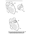
ここで、心臓の電気解剖学的マップ72、対応する三次元解剖学的画像74、および複合画像75を示す図5について説明する。図5では、電気解剖学的マップ72の一部分の複製部分が、本発明の開示された実施形態にしたがって、解剖学的画像74と位置合わせされている。画像は、上述のようにして取得され、再構築される。図の下部に参照ECG記録76が示されている。電気解剖学的マップ72は、相対的に低い電圧の領域78を示している。心筋の瘢痕と合致する対象の領域80が、解剖学的画像74上に描かれている。心臓の瘢痕組織は、一般的に、領域78によって示されるように、電気解剖学的マップで健康的な組織より低い電圧を示す点で、心筋機能に影響を及ぼす。複合画像は、領域80を領域78と位置合わせすることによって形成される。
[Functional image processing technology]
Reference is now made to FIG. 5, which shows an
〔代替的実施形態〕
本発明の他の一実施形態によれば、画像の断片化のために電位が使用されうる。例えば、心臓の弁の場所および形状は、弁と周囲の心内膜との間の電位の差異に基づいて描かれうる。
Alternative embodiments
According to another embodiment of the invention, potentials can be used for image fragmentation. For example, the location and shape of the heart valve can be drawn based on the potential difference between the valve and the surrounding endocardium.
ここで、心臓の電気解剖学的マップ82、同時に取得された対応する三次元解剖学的画像84、および複合画像90を示す図6について説明する。図6では、電気解剖学的マップ82の複製部分が、本発明の開示された実施形態にしたがって、解剖学的画像84と位置合わせされている。オペレーターは、心臓の形態学上の外見に基づいて、僧帽弁および大動脈弁の場所を解剖学的画像84上で決定することができる。電気解剖学的マップ82上、比較的低い電気的活動の領域86、88がそれぞれ大動脈弁と僧帽弁とを示している。領域86、88を含む電気解剖学的マップ82の関連部分が解剖学的画像84のオペレーターによって特定された領域と位置合わせされた後、オペレーターは、ほぼリアルタイムで、結果として得られた心臓全体の複合画像90を利用できるようになる。
Reference is now made to FIG. 6, which shows an
他の電気的特徴も、断片化および位置合わせに使用しうる。例えば、心房から心室へのマッピングカテーテルの移動は、カテーテルが心室に進入する際における、局所的心電図中のP波の消滅によって特定しうる。他の一例では、マッピングカテーテルと体表電極との間の電気的インピーダンスが計測される、インピーダンスに基づく場所確認システム(impedance−based location systems)において、肺静脈の場所は、カテーテルが左心房から静脈中へ移動する際におけるインピーダンスの上昇によって特定されうる。 Other electrical features can also be used for fragmentation and alignment. For example, the movement of the mapping catheter from the atrium to the ventricle can be identified by the disappearance of the P wave in the local electrocardiogram as the catheter enters the ventricle. In another example, in an impedance-based location system where the electrical impedance between the mapping catheter and the body surface electrode is measured, the location of the pulmonary vein is such that the catheter is placed in the vein from the left atrium. It can be specified by an increase in impedance when moving in.
本発明の一実施形態では、バイオセンス・ウェブスター(Biosense−Webster)社から入手可能なNOGA(登録商標)ソフトウェアが位置合わせのために使用される。このソフトウェアは、フィルタを使用してバイポーラEKG中のP波を検出し、これにより、基底帯(basal zone)の弁の線維輪上の点を、明確に心房中にある点と識別することができる。使用されるアルゴリズムは、基本的に、体表QRS群およびそのP波の場所を画定し、次いで、バイポーラウインドウ中、その時間範囲における偏差を探索する。二つの定義済みパラメータが合致しなければならない:(1)偏差のピーク間の電圧が0〜0.5mVの範囲になければならない。(2)QRS群の大きさに対する偏差の割合が、0〜100%の範囲になければならない。一般に、0.1mVのピーク間の電圧は既にノイズレベルを上回っており、真の偏差信号を表していると考えられる。25%の比率で十分であるようである。第一または第二のパラメータが増加すると、基準に合致する点がより少なくなり、より正しい基底点(basal point)を見失うことになる。他方、パラメータが減少すると、有効な点が減少することになる(偽陽性の増加)。典型的な左心室のマップでは、このアルゴリズムは、一般的に、3〜10ポイントを検出するが、これらはほとんど常に基底の場所である。 In one embodiment of the invention, NOGA® software available from Biosense-Webster is used for alignment. The software uses a filter to detect P-waves in bipolar EKG, thereby distinguishing points on the annulus of the basal zone valve from points that are clearly in the atria it can. The algorithm used basically defines the body surface QRS complex and its P-wave location, and then searches for deviations in that time range in the bipolar window. Two predefined parameters must be met: (1) The voltage between the peaks of the deviation must be in the range of 0-0.5 mV. (2) The ratio of deviation to the size of the QRS group must be in the range of 0 to 100%. In general, the peak-to-peak voltage of 0.1 mV already exceeds the noise level and is considered to represent a true deviation signal. A ratio of 25% seems to be sufficient. As the first or second parameter increases, fewer points meet the criteria and you lose sight of the more correct basal point. On the other hand, decreasing the parameter will decrease the effective points (increased false positives). In a typical left ventricular map, the algorithm generally detects 3-10 points, which are almost always the base location.
本発明のさらに他の一実施形態では、患者が胸部のコンピュータ断層撮影(CT)画像処理の間に体表電極の「ベスト」を着用していると、電極がCT画像中に現れる。この電極を使用して実行されるECG測定により、心臓表面に向けて内向きに投影しうる電気的モデルが得られる。心臓の電気解剖学的マップからも同様に、体表に向けて外向きに投影しうる心臓の電気的モデルが得られる。これら二つの電気的モデルはお互いに位置合わせされて、心臓の電気解剖学的マップをCT画像と位置合わせするようにしうる。この位置合わせアルゴリズムは、場所情報と電気的活動情報との両方を使用する。 In yet another embodiment of the invention, the electrode appears in the CT image when the patient wears a “vest” of body surface electrodes during computed tomography (CT) imaging of the chest. ECG measurements performed using this electrode provide an electrical model that can be projected inward toward the heart surface. Similarly, an electroanatomical map of the heart provides an electrical model of the heart that can be projected outwardly toward the body surface. These two electrical models may be aligned with each other so that the electroanatomical map of the heart is aligned with the CT image. This alignment algorithm uses both location information and electrical activity information.
画像の位置合わせおよび断片化においてマッピングされ使用されうるその他の生理的データには、温度、血流速度、化学的性質および機械的活動が含まれる。例えば、上記の米国特許第6,716,166号および同第6,773,402号に開示されたように、超音波カテーテルによってドップラー画像中で検出された高速流の領域が特定され、三次元解剖学的画像で観察される血管中の狭窄と位置合わせされうる。他の一例として、虚血を示す低いNADPHレベルの心臓領域を特定するために化学センサーを使用しうる。このような領域は、磁気共鳴スペクトロスコピー(magnetic resonance sepctroscopy)を使用して得られた画像上に観察された、対応する虚血性の領域と位置合わせし得る。論文「31P磁気共鳴スペクトロスコピーによる冠動脈疾病における心臓リン代謝の定量的計測(Quantitative Measurements of Cardiac Phosphorus Metabolites in Coronary Artery Disease by 31P Magnetic Resonance Spectroscopy)」,ヤベ タカヒロ他(Takahiro Yabe et al.),循環器科(Circulation)、1995年、92号、p.15−23(1995;92:15−23)に記述された技術は、このような領域を示すのに適している。 Other physiological data that can be mapped and used in image registration and fragmentation include temperature, blood flow velocity, chemistry, and mechanical activity. For example, as disclosed in US Pat. Nos. 6,716,166 and 6,773,402 above, regions of high velocity flow detected in Doppler images by an ultrasonic catheter are identified and three-dimensional It can be aligned with the stenosis in the blood vessel observed in the anatomical image. As another example, a chemical sensor may be used to identify a low NADPH level cardiac region indicative of ischemia. Such regions can be aligned with corresponding ischemic regions observed on images obtained using magnetic resonance spectroscopy. Paper “Quantitative Measurements of Cardiac Phosphorous Metabolites in Coronary Artery Dissociation Tachyharcos Respiratory Thirty-one Quantitative Measurement of Cardiac Phosphorus Metabolism in Coronary Diseases” Circulation, 1995, No. 92, p. The technique described in 15-23 (1995; 92: 15-23) is suitable for indicating such areas.
当業者ならば、本発明が上記に示した特定のものに制限されるわけではないことを認識するであろう。むしろ、本発明の範囲には、上記の種々の特徴の組合せおよび下位の組合せの両方ならびに、上記の説明を読んだ当業者が想到するであろうその変形および修正であって、先行技術にはないものが含まれる。 Those skilled in the art will recognize that the present invention is not limited to the specifics set forth above. Rather, the scope of the present invention includes both the various feature combinations and sub-combinations described above, as well as variations and modifications thereof that would occur to those skilled in the art upon reading the above description, Something not included.
〔実施の態様〕
本発明の好ましい実施態様は以下の通りである。
(1)被験者の身体中の構造をマッピングするための方法において、
前記構造の三次元画像をとらえるステップであって、前記構造は、前記画像中に現れる解剖学的特徴を有する、ステップと、
前記構造の多数の点で計測された前記構造に関する機能的情報を含む前記構造の三次元マップであって、前記構造の機能的特徴を表すマップ、を含む機能的モデルを発生させる、ステップと、
前記機能的特徴の少なくとも一つを、前記画像中の前記解剖学的特徴の対応する少なくとも一つと自動的に同定することにより、前記画像を前記マップと位置合わせする、ステップと、
前記マップからの前記機能的情報を、前記画像に位置合わせして表示する、ステップと、
を含む、方法。
(2)実施態様1に記載の方法において、
前記プローブを前記構造中に挿入するステップであって、前記プローブが、前記プローブの位置情報と方位情報とを決めるための位置センサーを有するステップ、
をさらに含む、方法。
(3)実施態様2に記載の方法において、
機能的モデルを発生させる前記ステップが、前記プローブを前記構造上の多数の接触点と接触させることにより電気的モデルを発生させ、前記プローブの前記位置センサーを用いて、前記接触点のそれぞれに関連する位置情報と方位情報とを得ることを含む、方法。
(4)実施態様3に記載の方法において、
前記構造が心臓を含み、前記機能的情報が、前記接触点のそれぞれで撮られた局所的心電図の特徴を含む、方法。
(5)実施態様4に記載の方法において、
前記特徴がP波であり、
前記P波が存在するときには、前記接触点の心房の場所を特定し、前記P波が存在しないときには、前記接触点の心室の場所を特定するステップ、をさらに含む、
方法。
Embodiment
Preferred embodiments of the present invention are as follows.
(1) In a method for mapping a structure in a subject's body,
Capturing a three-dimensional image of the structure, the structure having anatomical features appearing in the image;
Generating a functional model comprising a three-dimensional map of the structure containing functional information about the structure measured at a number of points of the structure, the map representing functional features of the structure;
Aligning the image with the map by automatically identifying at least one of the functional features as a corresponding at least one of the anatomical features in the image;
Displaying the functional information from the map in alignment with the image;
Including a method.
(2) In the method according to Embodiment 1,
Inserting the probe into the structure, the probe having a position sensor for determining position information and orientation information of the probe;
Further comprising a method.
(3) In the method according to
The step of generating a functional model generates an electrical model by contacting the probe with a number of contact points on the structure and associated with each of the contact points using the position sensor of the probe. Obtaining position information and orientation information.
(4) In the method according to
The method wherein the structure includes a heart and the functional information includes local electrocardiographic features taken at each of the contact points.
(5) In the method according to embodiment 4,
The characteristic is P wave,
Identifying the atrial location of the contact point when the P wave is present, and further identifying the ventricular location of the contact point when the P wave is not present,
Method.
(6)実施態様3に記載の方法において、
前記機能的情報が、前記接触点における電圧の大きさを含む、方法。
(7)実施態様6に記載の方法において、
前記構造が心臓を含み、
前記心臓のある領域の輪郭を描くことにより、前記心臓中の心筋の瘢痕を特定するステップ、をさらに含み、
前記領域中の前記接触点が、前記領域外にある前記接触点より低い電圧を有する、
方法。
(8)実施態様6に記載の方法において、
前記構造が心臓を含み、
前記心臓のある領域の輪郭を描くことにより、前記心臓の弁を特定するステップ、をさらに含み、
前記接触点が、前記領域外にある他の前記接触点の電圧とは異なる電圧を有する、
方法。
(9)実施態様3に記載の方法において、
前記機能的情報が、前記身体の表面と前記接触点のそれぞれとの間のインピーダンスを含む、方法。
(10)実施態様3に記載の方法において、
前記画像が、前記身体の胸部のコンピュータ断層撮影画像であり、当該断層撮影画像は、前記身体の心臓の表示を含む、方法。
(6) In the method according to
The method wherein the functional information includes a magnitude of a voltage at the contact point.
(7) In the method according to
The structure includes a heart;
Identifying a myocardial scar in the heart by delineating a region of the heart,
The contact point in the region has a lower voltage than the contact point outside the region;
Method.
(8) In the method according to
The structure includes a heart;
Further comprising identifying the heart valve by delineating a region of the heart;
The contact point has a voltage different from the voltage of the other contact points outside the region;
Method.
(9) In the method according to
The method wherein the functional information includes an impedance between the body surface and each of the contact points.
(10) In the method according to
The method, wherein the image is a computed tomography image of the chest of the body, the tomography image comprising a representation of the heart of the body.
(11)実施態様10に記載の方法において、
複数の表面電極を前記胸部上に配置するステップと、
前記表面電極を用いて心電図計測を実行することによって外部電気的モデルを発生させるステップと
さらに含み、
位置合わせする前記ステップが、前記電気的モデルを前記心臓の前記表示上に外向きに投影し、前記外部電気的モデルを前記心臓の前記表示上に内向きに投影し、前記外部電気的モデルを前記電気的モデルおよび前記心臓の前記表示と位置合わせして配置する、ステップ、をさらに含む、
方法。
(12)実施態様1に記載の方法において、
前記画像が超音波画像である、方法。
(13)実施態様1に記載の方法において、
前記機能的情報が、温度、前記構造中の流体の流速、前記構造の化学的性質または機械的活動である、方法。
(14)被験者の身体中の構造をマッピングするための装置において、
前記構造の三次元画像をとらえるための画像処理装置であって、前記構造が前記画像中に現れる解剖学的特徴を有する、画像処理装置と、
前記画像処理装置にリンクしたプロセッサであって、前記プロセッサは、前記構造の多数の点で計測された前記構造に関する機能的情報を含む前記構造の三次元マップを含む機能的モデルを発生させるために作動し、前記マップは、前記構造の機能的特徴を表し、前記プロセッサは、前記機能的特徴の少なくとも一つを、前記画像中の前記解剖学的特徴の対応する少なくとも一つと自動的に同定することにより、前記画像を前記マップと位置合わせするように作動する、プロセッサと、
前記プロセッサにリンクした表示装置であって、前記マップからの前記機能的情報を前記画像に位置合わせして表示するための、表示装置と、
を含む、装置。
(15)実施態様14に記載の装置において、
前記プロセッサにリンクし、前記構造中に挿入するよう構成されたプローブであって、前記プローブが、前記プローブの位置情報および方位情報を決めるための位置センサーを有する、プローブ、
をさらに含む、装置。
(11) In the method according to
Placing a plurality of surface electrodes on the chest;
Generating an external electrical model by performing electrocardiogram measurements using the surface electrode; and
The step of aligning projects the electrical model outward on the display of the heart, projects the external electrical model inward on the display of the heart, and converts the external electrical model to Further comprising: aligning with the electrical model and the representation of the heart.
Method.
(12) In the method according to embodiment 1,
A method wherein the image is an ultrasound image.
(13) In the method according to embodiment 1,
The method wherein the functional information is temperature, flow rate of fluid in the structure, chemistry or mechanical activity of the structure.
(14) In an apparatus for mapping structures in the body of a subject,
An image processing device for capturing a three-dimensional image of the structure, wherein the structure has anatomical features that appear in the image;
A processor linked to the image processing device for generating a functional model including a three-dimensional map of the structure containing functional information about the structure measured at a number of points of the structure In operation, the map represents functional features of the structure, and the processor automatically identifies at least one of the functional features as a corresponding at least one of the anatomical features in the image. A processor operable to align the image with the map;
A display device linked to the processor for displaying the functional information from the map in alignment with the image; and
Including the device.
(15) In the device according to embodiment 14,
A probe linked to the processor and configured to be inserted into the structure, wherein the probe comprises a position sensor for determining position information and orientation information of the probe;
Further comprising an apparatus.
(16)実施態様15に記載の装置において、
前記プローブが前記構造上の多数の接触点と接触しているときには、前記機能的モデルが電気的モデルを含み、前記プローブの前記位置センサーに応答して、前記プロセッサが、前記接触点のそれぞれに関連する位置情報および方位情報を得るように作動する、装置。
(17)実施態様16に記載の装置において、
前記構造が心臓を含み、
前記機能的情報が、前記接触点のそれぞれにおいて撮られた局所的心電図の特徴を含む、
装置。
(18)実施態様16に記載の装置において、
前記機能的情報が、前記接触点における電圧の大きさを含む、装置。
(19)実施態様16に記載の装置において、
前記機能的情報が、前記身体の表面と前記接触点のそれぞれとの間のインピーダンスをさらに含む、装置。
(20)実施態様16に記載の装置において、
前記画像が、前記身体の胸部のコンピュータ断層撮影画像であり、当該断層撮影画像は、前記身体の心臓の表示を含む、装置。
(16) In the device according to embodiment 15,
When the probe is in contact with multiple contact points on the structure, the functional model includes an electrical model, and in response to the position sensor of the probe, the processor applies to each of the contact points. A device that operates to obtain relevant location and orientation information.
(17) In the device according to embodiment 16,
The structure includes a heart;
The functional information includes features of local electrocardiograms taken at each of the contact points;
apparatus.
(18) In the device according to embodiment 16,
The apparatus, wherein the functional information includes a magnitude of a voltage at the contact point.
(19) In the device according to embodiment 16,
The apparatus, wherein the functional information further includes an impedance between the body surface and each of the contact points.
(20) In the device according to embodiment 16,
The apparatus, wherein the image is a computed tomography image of the chest of the body, the tomography image including a display of the heart of the body.
(21)実施態様14に記載の装置において、
前記画像が超音波画像である、装置。
(22)実施態様14に記載の装置において、
前記機能的情報が、温度、前記構造中の流体の流速、前記構造の化学的性質または機械的活動である、装置。
(21) In the device according to embodiment 14,
An apparatus wherein the image is an ultrasound image.
(22) In the device according to embodiment 14,
The device wherein the functional information is temperature, flow rate of fluid in the structure, chemistry or mechanical activity of the structure.
Claims (9)
前記構造の三次元画像をとらえるための画像処理装置であって、前記構造が前記画像中に現れる解剖学的特徴を有する、画像処理装置と、
前記画像処理装置にリンクしたプロセッサであって、前記プロセッサは、前記構造の多数の点で計測された前記構造に関する機能的情報を含む前記構造の三次元マップを含む機能的モデルを発生させるために作動し、前記マップは、前記構造の第1の機能的特徴および第2の機能的特徴を表し、前記プロセッサは、前記第1の機能的特徴を含み前記マップ内の一部の領域である第1の領域を、オペレータによって特定された前記画像中の第1の地点と位置合わせすると共に、前記第2の機能的特徴を含み前記マップ内の一部の領域であって前記第1の領域と異なる領域である第2の領域を、オペレータによって特定され前記第1の地点と異なる前記画像中の第2の地点と位置合わせするように作動する、プロセッサと、
前記プロセッサにリンクした表示装置であって、前記マップからの前記機能的情報を前記画像に位置合わせして表示するための、表示装置と、
を含み、
前記表示装置は、前記画像、前記画像の一部の領域における前記第1の機能的特徴、及び、前記画像の他の一部の領域における前記第2の機能的特徴を表示する、装置。 In a device for mapping structures in the body of a subject,
An image processing device for capturing a three-dimensional image of the structure, wherein the structure has anatomical features that appear in the image;
A processor linked to the image processing device for generating a functional model including a three-dimensional map of the structure containing functional information about the structure measured at a number of points of the structure actuated, the map represents the first functional feature and the second functional characteristics of the structure, wherein the processor is the first functional feature in some areas of unrealized said map a first region, as well as aligned with the first point in the image specified by the operator, the second functional feature of unrealized the map in a part of region of the first of A processor operative to align a second region that is different from the region with a second point in the image that is identified by an operator and that is different from the first point ;
A display device linked to the processor for displaying the functional information from the map in alignment with the image; and
Only including,
The display device displays the image, the first functional feature in a partial region of the image, and the second functional feature in another partial region of the image .
前記プロセッサにリンクし、前記構造中に挿入するよう構成されたプローブであって、前記プローブが、前記プローブの位置情報および方位情報を決めるための位置センサーを有する、プローブ、
をさらに含む、装置。 The apparatus of claim 1.
A probe linked to the processor and configured to be inserted into the structure, wherein the probe comprises a position sensor for determining position information and orientation information of the probe;
Further comprising an apparatus.
前記プローブが前記構造上の多数の接触点と接触しているときには、前記機能的モデルが電気的モデルを含み、前記プローブの前記位置センサーに応答して、前記プロセッサが、前記接触点のそれぞれに関連する位置情報および方位情報を得るように作動する、装置。 The apparatus of claim 2.
When the probe is in contact with multiple contact points on the structure, the functional model includes an electrical model, and in response to the position sensor of the probe, the processor applies to each of the contact points. A device that operates to obtain relevant location and orientation information.
前記構造が心臓を含み、
前記機能的情報が、前記接触点のそれぞれにおいて撮られた局所的心電図の特徴を含む、
装置。 The apparatus of claim 3.
The structure includes a heart;
The functional information includes features of local electrocardiograms taken at each of the contact points;
apparatus.
前記機能的情報が、前記接触点における電圧の大きさを含む、装置。 The apparatus of claim 3.
The apparatus, wherein the functional information includes a magnitude of a voltage at the contact point.
前記機能的情報が、前記身体の表面と前記接触点のそれぞれとの間のインピーダンスをさらに含む、装置。 The apparatus of claim 3.
The apparatus, wherein the functional information further includes an impedance between the body surface and each of the contact points.
前記画像が、前記身体の胸部のコンピュータ断層撮影画像であり、当該断層撮影画像は、前記身体の心臓の表示を含む、装置。 The apparatus of claim 3.
The apparatus, wherein the image is a computed tomography image of the chest of the body, the tomography image including a display of the heart of the body.
前記画像が超音波画像である、装置。 The apparatus of claim 1.
An apparatus wherein the image is an ultrasound image.
前記機能的情報が、温度、前記構造中の流体の流速、前記構造の化学的性質または機械的活動である、装置。 The apparatus of claim 1.
The device wherein the functional information is temperature, flow rate of fluid in the structure, chemistry or mechanical activity of the structure.
Applications Claiming Priority (2)
| Application Number | Priority Date | Filing Date | Title |
|---|---|---|---|
| US11/215,435 | 2005-08-30 | ||
| US11/215,435 US20070049817A1 (en) | 2005-08-30 | 2005-08-30 | Segmentation and registration of multimodal images using physiological data |
Publications (2)
| Publication Number | Publication Date |
|---|---|
| JP2007061617A JP2007061617A (en) | 2007-03-15 |
| JP5253723B2 true JP5253723B2 (en) | 2013-07-31 |
Family
ID=37497451
Family Applications (1)
| Application Number | Title | Priority Date | Filing Date |
|---|---|---|---|
| JP2006231962A Expired - Fee Related JP5253723B2 (en) | 2005-08-30 | 2006-08-29 | Fragmentation and registration of multimodal images using physiological data |
Country Status (10)
| Country | Link |
|---|---|
| US (1) | US20070049817A1 (en) |
| EP (1) | EP1760661B1 (en) |
| JP (1) | JP5253723B2 (en) |
| KR (1) | KR20070026135A (en) |
| CN (1) | CN1981710B (en) |
| AU (1) | AU2006203713B2 (en) |
| BR (1) | BRPI0603750A (en) |
| CA (1) | CA2557027C (en) |
| IL (1) | IL177625A0 (en) |
| MX (1) | MXPA06009867A (en) |
Families Citing this family (179)
| Publication number | Priority date | Publication date | Assignee | Title |
|---|---|---|---|---|
| US7697972B2 (en) | 2002-11-19 | 2010-04-13 | Medtronic Navigation, Inc. | Navigation system for cardiac therapies |
| US7599730B2 (en) | 2002-11-19 | 2009-10-06 | Medtronic Navigation, Inc. | Navigation system for cardiac therapies |
| US8180601B2 (en) | 2006-03-09 | 2012-05-15 | The Cleveland Clinic Foundation | Systems and methods for determining volume of activation for deep brain stimulation |
| US8209027B2 (en) | 2004-07-07 | 2012-06-26 | The Cleveland Clinic Foundation | System and method to design structure for delivering electrical energy to tissue |
| US7346382B2 (en) * | 2004-07-07 | 2008-03-18 | The Cleveland Clinic Foundation | Brain stimulation models, systems, devices, and methods |
| US8784336B2 (en) | 2005-08-24 | 2014-07-22 | C. R. Bard, Inc. | Stylet apparatuses and methods of manufacture |
| US8589316B2 (en) | 2009-08-27 | 2013-11-19 | The Cleveland Clinic Foundation | System and method to estimate region of tissue activation |
| US8606360B2 (en) * | 2006-03-09 | 2013-12-10 | The Cleveland Clinic Foundation | Systems and methods for determining volume of activation for spinal cord and peripheral nerve stimulation |
| US7855723B2 (en) * | 2006-03-21 | 2010-12-21 | Biosense Webster, Inc. | Image registration using locally-weighted fitting |
| CA2932956C (en) | 2006-08-03 | 2020-04-14 | Christoph Scharf | Method and device for determining and presenting surface charge and dipole densities on cardiac walls |
| US7831076B2 (en) | 2006-12-08 | 2010-11-09 | Biosense Webster, Inc. | Coloring electroanatomical maps to indicate ultrasound data acquisition |
| US7941213B2 (en) * | 2006-12-28 | 2011-05-10 | Medtronic, Inc. | System and method to evaluate electrode position and spacing |
| US7996055B2 (en) | 2006-12-29 | 2011-08-09 | St. Jude Medical, Atrial Fibrillation Division, Inc. | Cardiac navigation system including electrode array for use therewith |
| US7957784B2 (en) * | 2006-12-29 | 2011-06-07 | St. Jude Medical, Atrial Fibrillation Division, Inc. | Body surface mapping system |
| US20080170654A1 (en) * | 2007-01-15 | 2008-07-17 | John Eric Tkaczyk | Method and apparatus of ct cardiac diagnostic imaging using a priori motion information from 3d ultrasound and ecg gating |
| WO2008087629A2 (en) * | 2007-01-16 | 2008-07-24 | Simbionix Ltd. | Preoperative surgical simulation |
| US8543338B2 (en) * | 2007-01-16 | 2013-09-24 | Simbionix Ltd. | System and method for performing computerized simulations for image-guided procedures using a patient specific model |
| CN101711125B (en) | 2007-04-18 | 2016-03-16 | 美敦力公司 | For the active fixing medical electrical leads of long-term implantable that non-fluorescence mirror is implanted |
| JP5173303B2 (en) * | 2007-07-27 | 2013-04-03 | 株式会社東芝 | Medical image processing apparatus and medical image diagnostic apparatus |
| JP5337367B2 (en) * | 2007-10-31 | 2013-11-06 | 株式会社東芝 | Medical image display device |
| US8103070B2 (en) * | 2007-11-22 | 2012-01-24 | Toshiba Medical Visualization Systems Europe, Limited | Volume rendering apparatus and method |
| US9521961B2 (en) | 2007-11-26 | 2016-12-20 | C. R. Bard, Inc. | Systems and methods for guiding a medical instrument |
| US10751509B2 (en) | 2007-11-26 | 2020-08-25 | C. R. Bard, Inc. | Iconic representations for guidance of an indwelling medical device |
| US9649048B2 (en) | 2007-11-26 | 2017-05-16 | C. R. Bard, Inc. | Systems and methods for breaching a sterile field for intravascular placement of a catheter |
| US8388541B2 (en) | 2007-11-26 | 2013-03-05 | C. R. Bard, Inc. | Integrated system for intravascular placement of a catheter |
| US8781555B2 (en) | 2007-11-26 | 2014-07-15 | C. R. Bard, Inc. | System for placement of a catheter including a signal-generating stylet |
| US8320711B2 (en) | 2007-12-05 | 2012-11-27 | Biosense Webster, Inc. | Anatomical modeling from a 3-D image and a surface mapping |
| JP5629582B2 (en) * | 2007-12-13 | 2014-11-19 | コーニンクレッカ フィリップス エヌ ヴェ | Method, system and computer program for retrieving data from a set of medical image data |
| CN101903909B (en) * | 2007-12-18 | 2013-05-29 | 皇家飞利浦电子股份有限公司 | System for multimodality fusion of imaging data based on statistical models of anatomy |
| US20110175903A1 (en) * | 2007-12-20 | 2011-07-21 | Quantum Medical Technology, Inc. | Systems for generating and displaying three-dimensional images and methods therefor |
| WO2009090547A2 (en) | 2008-01-17 | 2009-07-23 | Christoph Scharf | A device and method for the geometric determination of electrical dipole densities on the cardiac wall |
| US9220889B2 (en) | 2008-02-11 | 2015-12-29 | Intelect Medical, Inc. | Directional electrode devices with locating features |
| US8019440B2 (en) | 2008-02-12 | 2011-09-13 | Intelect Medical, Inc. | Directional lead assembly |
| US8917916B2 (en) * | 2008-02-25 | 2014-12-23 | Colin Bruce Martin | Medical training method and apparatus |
| WO2009122343A1 (en) * | 2008-04-03 | 2009-10-08 | Koninklijke Philips Electronics N.V. | Respiration determination apparatus |
| US8260395B2 (en) * | 2008-04-18 | 2012-09-04 | Medtronic, Inc. | Method and apparatus for mapping a structure |
| US8340751B2 (en) * | 2008-04-18 | 2012-12-25 | Medtronic, Inc. | Method and apparatus for determining tracking a virtual point defined relative to a tracked member |
| US8839798B2 (en) * | 2008-04-18 | 2014-09-23 | Medtronic, Inc. | System and method for determining sheath location |
| US8532734B2 (en) | 2008-04-18 | 2013-09-10 | Regents Of The University Of Minnesota | Method and apparatus for mapping a structure |
| US8494608B2 (en) * | 2008-04-18 | 2013-07-23 | Medtronic, Inc. | Method and apparatus for mapping a structure |
| US8663120B2 (en) * | 2008-04-18 | 2014-03-04 | Regents Of The University Of Minnesota | Method and apparatus for mapping a structure |
| ES2580175T3 (en) | 2008-05-15 | 2016-08-19 | Intelect Medical Inc. | Clinical programmer system and procedure to direct activation volumes |
| US9272153B2 (en) | 2008-05-15 | 2016-03-01 | Boston Scientific Neuromodulation Corporation | VOA generation system and method using a fiber specific analysis |
| US8200466B2 (en) | 2008-07-21 | 2012-06-12 | The Board Of Trustees Of The Leland Stanford Junior University | Method for tuning patient-specific cardiovascular simulations |
| ES2525525T3 (en) | 2008-08-22 | 2014-12-26 | C.R. Bard, Inc. | Catheter assembly that includes ECG and magnetic sensor assemblies |
| DE102008047644B4 (en) * | 2008-09-17 | 2015-09-10 | Siemens Aktiengesellschaft | Method for registering two imaging modalities |
| US8644946B2 (en) * | 2008-12-04 | 2014-02-04 | The Cleveland Clinic Foundation | System and method to define target volume for stimulation in brain |
| US8175681B2 (en) | 2008-12-16 | 2012-05-08 | Medtronic Navigation Inc. | Combination of electromagnetic and electropotential localization |
| CN101836862B (en) * | 2009-03-16 | 2014-03-26 | 上海微创医疗器械(集团)有限公司 | Three-dimensional mapping method of human chamber inner wall and equipment and system thereof |
| US9405886B2 (en) | 2009-03-17 | 2016-08-02 | The Board Of Trustees Of The Leland Stanford Junior University | Method for determining cardiovascular information |
| CN102395999B (en) * | 2009-04-15 | 2014-08-20 | 皇家飞利浦电子股份有限公司 | Quantification of medical image data |
| JP5859431B2 (en) | 2009-06-08 | 2016-02-10 | エムアールアイ・インターヴェンションズ,インコーポレイテッド | MRI guided intervention system capable of tracking flexible internal devices and generating dynamic visualization in near real time |
| US9532724B2 (en) | 2009-06-12 | 2017-01-03 | Bard Access Systems, Inc. | Apparatus and method for catheter navigation using endovascular energy mapping |
| US8369930B2 (en) | 2009-06-16 | 2013-02-05 | MRI Interventions, Inc. | MRI-guided devices and MRI-guided interventional systems that can track and generate dynamic visualizations of the devices in near real time |
| EP2464407A4 (en) | 2009-08-10 | 2014-04-02 | Bard Access Systems Inc | Devices and methods for endovascular electrography |
| US8494613B2 (en) | 2009-08-31 | 2013-07-23 | Medtronic, Inc. | Combination localization system |
| US8494614B2 (en) | 2009-08-31 | 2013-07-23 | Regents Of The University Of Minnesota | Combination localization system |
| RU2550660C2 (en) * | 2009-09-14 | 2015-05-10 | Конинклейке Филипс Электроникс Н.В. | Device and method of non-invasive intracardial electrocardiography with formation of image with application of magnetic particles |
| US8355774B2 (en) * | 2009-10-30 | 2013-01-15 | Medtronic, Inc. | System and method to evaluate electrode position and spacing |
| JP5689662B2 (en) * | 2009-12-09 | 2015-03-25 | 株式会社東芝 | Ultrasonic diagnostic apparatus, ultrasonic image processing apparatus, ultrasonic image processing program, medical image diagnostic apparatus, medical image processing apparatus, and medical image processing program |
| US8761478B2 (en) * | 2009-12-15 | 2014-06-24 | General Electric Company | System and method for tomographic data acquisition and image reconstruction |
| US10069668B2 (en) * | 2009-12-31 | 2018-09-04 | Mediguide Ltd. | Compensation of motion in a moving organ using an internal position reference sensor |
| CN102821679B (en) | 2010-02-02 | 2016-04-27 | C·R·巴德股份有限公司 | For the apparatus and method that catheter navigation and end are located |
| US20110213260A1 (en) * | 2010-02-26 | 2011-09-01 | Pacesetter, Inc. | Crt lead placement based on optimal branch selection and optimal site selection |
| US8204172B1 (en) | 2010-03-17 | 2012-06-19 | General Electric Company | System and method of prior image constrained image reconstruction using short scan image data and objective function minimization |
| ES2370727B2 (en) | 2010-03-18 | 2013-03-13 | Universidad Politécnica de Madrid | METHOD FOR DISPLAYING THE INFORMATION CONTAINED IN THREE-DIMENSIONAL IMAGES OF THE HEART. |
| EP2912999B1 (en) | 2010-05-28 | 2022-06-29 | C. R. Bard, Inc. | Apparatus for use with needle insertion guidance system |
| EP2575610B1 (en) | 2010-05-28 | 2022-10-05 | C. R. Bard, Inc. | Insertion guidance system for needles and medical components |
| JP5830090B2 (en) | 2010-06-14 | 2015-12-09 | ボストン サイエンティフィック ニューロモデュレイション コーポレイション | Programming interface for spinal nerve regulation |
| US8315812B2 (en) | 2010-08-12 | 2012-11-20 | Heartflow, Inc. | Method and system for patient-specific modeling of blood flow |
| MX338127B (en) | 2010-08-20 | 2016-04-04 | Bard Inc C R | Reconfirmation of ecg-assisted catheter tip placement. |
| CN101984928B (en) * | 2010-09-29 | 2012-06-13 | 北京大学 | Multi-mode molecular tomography system |
| US20120165671A1 (en) * | 2010-12-27 | 2012-06-28 | Hill Anthony D | Identification of objects in ultrasound |
| US10524765B2 (en) * | 2010-12-27 | 2020-01-07 | St. Jude Medical, Atrial Fibrillation Division, Inc. | Refinement of an anatomical model using ultrasound |
| US9875339B2 (en) | 2011-01-27 | 2018-01-23 | Simbionix Ltd. | System and method for generating a patient-specific digital image-based model of an anatomical structure |
| BR112013021977A2 (en) * | 2011-03-02 | 2018-06-12 | King S College London | method for displaying information of an object of interest, device for displaying information of an object of interest, medical imaging system, computer program element and computer readable medium |
| JP6193766B2 (en) | 2011-03-10 | 2017-09-06 | アクタス メディカル インク | A device for the geometric measurement of the electric dipole density of the heart wall. |
| US20130054270A1 (en) | 2011-03-29 | 2013-02-28 | Boston Scientific Neuromodulation Corporation | Communication interface for therapeutic stimulation providing systems |
| US9592389B2 (en) | 2011-05-27 | 2017-03-14 | Boston Scientific Neuromodulation Corporation | Visualization of relevant stimulation leadwire electrodes relative to selected stimulation information |
| US9808179B2 (en) | 2011-08-03 | 2017-11-07 | Flip Technologies Limited | Catheter and a system and a method for locating a catheter in a vessel |
| WO2013023076A2 (en) | 2011-08-09 | 2013-02-14 | Boston Scientific Neuromodulation Corporation | Control and/or quantification of target stimulation volume overlap and interface therefor |
| EP2741818B1 (en) | 2011-08-09 | 2019-11-20 | Boston Scientific Neuromodulation Corporation | Voa generation system and method using a fiber specific analysis |
| WO2013023085A2 (en) | 2011-08-09 | 2013-02-14 | Boston Scientific Neuromodulation Corporation | Systems and methods for stimulation-related volume analysis, creation, and sharing |
| WO2013023073A1 (en) | 2011-08-09 | 2013-02-14 | Boston Scientific Neuromodulation Corporation | System and method for weighted atlas generation |
| WO2013033539A1 (en) | 2011-09-01 | 2013-03-07 | Boston Scientific Neuromodulation Corporation | Methods and system for targeted brain stimulation using electrical parameter maps |
| WO2013056050A1 (en) * | 2011-10-12 | 2013-04-18 | Cardioinsight Technologies, Inc. | Sensing zone for spatially relevant electrical information |
| US9081488B2 (en) | 2011-10-19 | 2015-07-14 | Boston Scientific Neuromodulation Corporation | Stimulation leadwire and volume of activation control and display interface |
| EP2830485B1 (en) * | 2012-03-27 | 2021-03-10 | Koninklijke Philips N.V. | Integration delayed optical feedback in image guidance |
| CN104486991B (en) | 2012-05-18 | 2017-09-01 | 皇家飞利浦有限公司 | Voxel is tagged using optical fiber shape sensing |
| US20130317339A1 (en) | 2012-05-23 | 2013-11-28 | Biosense Webster (Israel), Ltd. | Endobronchial catheter |
| WO2014025624A1 (en) | 2012-08-04 | 2014-02-13 | Boston Scientific Neuromodulation Corporation | Techniques and methods for storing and transferring registration, atlas, and lead information between medical devices |
| AU2013308910B2 (en) | 2012-08-28 | 2016-10-06 | Boston Scientific Neuromodulation Corporation | Parameter visualization, selection, and annotation interface |
| CN104812297B (en) | 2012-08-31 | 2017-05-17 | 阿库图森医疗有限公司 | Catheter system and methods of medical uses of same, including diagnostic and treatment uses for heart |
| JP6297289B2 (en) * | 2012-09-20 | 2018-03-20 | キヤノンメディカルシステムズ株式会社 | Image processing system, X-ray diagnostic apparatus and method of operating image processing apparatus |
| US9792412B2 (en) | 2012-11-01 | 2017-10-17 | Boston Scientific Neuromodulation Corporation | Systems and methods for VOA model generation and use |
| DE102012222201A1 (en) * | 2012-12-04 | 2014-06-18 | Siemens Aktiengesellschaft | Method and hybrid imaging modality for generating a combination image |
| JP6487336B2 (en) * | 2012-12-31 | 2019-03-20 | マコ サージカル コーポレーション | System and method for alignment using an ultrasound probe |
| EP2948063A1 (en) * | 2013-01-22 | 2015-12-02 | Koninklijke Philips N.V. | Ultrasound probe and ultrasound imaging system |
| WO2014115150A1 (en) | 2013-01-24 | 2014-07-31 | Tylerton International Holdings Inc. | Body structure imaging |
| JP6422894B2 (en) | 2013-02-08 | 2018-11-14 | アクタス メディカル インクAcutus Medical,Inc. | Expandable catheter assembly with flexible printed circuit board |
| US9031642B2 (en) * | 2013-02-21 | 2015-05-12 | Medtronic, Inc. | Methods for simultaneous cardiac substrate mapping using spatial correlation maps between neighboring unipolar electrograms |
| WO2014144029A2 (en) | 2013-03-15 | 2014-09-18 | Boston Scientific Neuromodulation Corporation | Clinical response data mapping |
| US10271810B2 (en) | 2013-04-02 | 2019-04-30 | St. Jude Medical International Holding S.à r. l. | Enhanced compensation of motion in a moving organ using processed reference sensor data |
| WO2014169103A2 (en) * | 2013-04-12 | 2014-10-16 | Ninepoint Medical, Inc. | Multiple aperture, multiple modal optical systems and methods |
| US9576107B2 (en) * | 2013-07-09 | 2017-02-21 | Biosense Webster (Israel) Ltd. | Model based reconstruction of the heart from sparse samples |
| US9351657B2 (en) * | 2013-07-19 | 2016-05-31 | Biosense Webster (Israel) Ltd. | Cardiac activity visualization with frequency discrimination |
| USD748137S1 (en) * | 2013-08-20 | 2016-01-26 | Biosense Webster (Israel) Ltd. | Portion of a computer screen with an icon |
| US10052495B2 (en) | 2013-09-08 | 2018-08-21 | Tylerton International Inc. | Detection of reduced-control cardiac zones |
| US10828011B2 (en) | 2013-09-13 | 2020-11-10 | Acutus Medical, Inc. | Devices and methods for determination of electrical dipole densities on a cardiac surface |
| CN105828875B (en) * | 2013-10-16 | 2019-08-20 | 皇家飞利浦有限公司 | Utilize the position of bio-mechanical Model estimator official |
| AU2014348865B2 (en) | 2013-11-14 | 2017-06-01 | Boston Scientific Neuromodulation Corporation | Systems, methods, and visualization tools for stimulation and sensing of neural systems with system-level interaction models |
| US9289145B2 (en) | 2013-12-05 | 2016-03-22 | Medtronic, Inc. | Identification of abnormal cardiac substrate during left-ventricular pacing |
| US9572535B2 (en) * | 2013-12-05 | 2017-02-21 | Biosense Webster (Israel) Ltd. | Dynamic mapping point filtering using a pre-acquired image |
| CN106102583A (en) | 2014-01-10 | 2016-11-09 | 泰勒顿国际公司 | Cicatrix and the detection of fiber heart area |
| CN105979868B (en) | 2014-02-06 | 2020-03-10 | C·R·巴德股份有限公司 | Systems and methods for guidance and placement of intravascular devices |
| WO2015148470A1 (en) | 2014-03-25 | 2015-10-01 | Acutus Medical, Inc. | Cardiac analysis user interface system and method |
| WO2015171742A1 (en) * | 2014-05-09 | 2015-11-12 | Boston Scientific Scimed, Inc. | Medical devices for mapping cardiac tissue |
| CN106456009A (en) | 2014-06-20 | 2017-02-22 | 波士顿科学医学有限公司 | Medical devices for mapping cardiac tissue |
| US9959388B2 (en) | 2014-07-24 | 2018-05-01 | Boston Scientific Neuromodulation Corporation | Systems, devices, and methods for providing electrical stimulation therapy feedback |
| US10272247B2 (en) | 2014-07-30 | 2019-04-30 | Boston Scientific Neuromodulation Corporation | Systems and methods for stimulation-related volume analysis, creation, and sharing with integrated surgical planning and stimulation programming |
| US10265528B2 (en) | 2014-07-30 | 2019-04-23 | Boston Scientific Neuromodulation Corporation | Systems and methods for electrical stimulation-related patient population volume analysis and use |
| EP3204112A1 (en) | 2014-10-07 | 2017-08-16 | Boston Scientific Neuromodulation Corporation | Systems, devices, and methods for electrical stimulation using feedback to adjust stimulation parameters |
| US9955889B2 (en) | 2014-11-03 | 2018-05-01 | Biosense Webster (Israel) Ltd. | Registration maps using intra-cardiac signals |
| PL227985B1 (en) | 2014-11-07 | 2018-02-28 | Medidata Społka Z Ograniczoną Odpowiedzialnością | Electrophysiology diagnostic catheter, preferably for obtaining endomycardial biopsy of heart muscle tissues |
| US10973584B2 (en) | 2015-01-19 | 2021-04-13 | Bard Access Systems, Inc. | Device and method for vascular access |
| US10362965B2 (en) * | 2015-04-22 | 2019-07-30 | Acclarent, Inc. | System and method to map structures of nasal cavity |
| US10593234B2 (en) | 2015-05-12 | 2020-03-17 | Acutus Medical, Inc. | Cardiac virtualization test tank and testing system and method |
| AU2016262547B9 (en) | 2015-05-12 | 2021-03-04 | Acutus Medical, Inc. | Ultrasound sequencing system and method |
| US10653318B2 (en) | 2015-05-13 | 2020-05-19 | Acutus Medical, Inc. | Localization system and method useful in the acquisition and analysis of cardiac information |
| US9956419B2 (en) | 2015-05-26 | 2018-05-01 | Boston Scientific Neuromodulation Corporation | Systems and methods for analyzing electrical stimulation and selecting or manipulating volumes of activation |
| US10780283B2 (en) | 2015-05-26 | 2020-09-22 | Boston Scientific Neuromodulation Corporation | Systems and methods for analyzing electrical stimulation and selecting or manipulating volumes of activation |
| WO2016210325A1 (en) | 2015-06-26 | 2016-12-29 | C.R. Bard, Inc. | Connector interface for ecg-based catheter positioning system |
| WO2017003946A1 (en) | 2015-06-29 | 2017-01-05 | Boston Scientific Neuromodulation Corporation | Systems and methods for selecting stimulation parameters based on stimulation target region, effects, or side effects |
| US10441800B2 (en) | 2015-06-29 | 2019-10-15 | Boston Scientific Neuromodulation Corporation | Systems and methods for selecting stimulation parameters by targeting and steering |
| US10638954B2 (en) * | 2015-07-23 | 2020-05-05 | Biosense Webster (Israel) Ltd. | Surface registration of a CT image with a magnetic tracking system |
| WO2017062378A1 (en) | 2015-10-09 | 2017-04-13 | Boston Scientific Neuromodulation Corporation | System and methods for clinical effects mapping for directional stimulations leads |
| US10271906B2 (en) | 2015-11-06 | 2019-04-30 | Biosense Webster (Israel) Ltd. | Updating a volumetric map |
| US10524695B2 (en) * | 2015-12-22 | 2020-01-07 | Biosense Webster (Israel) Ltd. | Registration between coordinate systems for visualizing a tool |
| US10244963B2 (en) * | 2015-12-22 | 2019-04-02 | Biosense Webster (Israel) Ltd. | Ascertaining a position and orientation for visualizing a tool |
| US10078713B2 (en) | 2015-12-24 | 2018-09-18 | Biosense Webster (Israel) Ltd. | Global mapping catheter contact optimization |
| WO2017132403A1 (en) * | 2016-01-26 | 2017-08-03 | The Regents Of The University Of California | Symplectomorphic image registration |
| US11000207B2 (en) | 2016-01-29 | 2021-05-11 | C. R. Bard, Inc. | Multiple coil system for tracking a medical device |
| US10716942B2 (en) | 2016-04-25 | 2020-07-21 | Boston Scientific Neuromodulation Corporation | System and methods for directional steering of electrical stimulation |
| JP6937321B2 (en) | 2016-05-03 | 2021-09-22 | アクタス メディカル インクAcutus Medical,Inc. | Cardiac information dynamic display system |
| US10776456B2 (en) | 2016-06-24 | 2020-09-15 | Boston Scientific Neuromodulation Corporation | Systems and methods for visual analytics of clinical effects |
| US10350404B2 (en) | 2016-09-02 | 2019-07-16 | Boston Scientific Neuromodulation Corporation | Systems and methods for visualizing and directing stimulation of neural elements |
| US10780282B2 (en) | 2016-09-20 | 2020-09-22 | Boston Scientific Neuromodulation Corporation | Systems and methods for steering electrical stimulation of patient tissue and determining stimulation parameters |
| WO2018071865A1 (en) | 2016-10-14 | 2018-04-19 | Boston Scientific Neuromodulation Corporation | Systems and methods for closed-loop determination of stimulation parameter settings for an electrical simulation system |
| US11266467B2 (en) | 2016-10-25 | 2022-03-08 | Navix International Limited | Systems and methods for registration of intra-body electrical readings with a pre-acquired three dimensional image |
| US11129574B2 (en) | 2016-12-12 | 2021-09-28 | Biosense Webster (Israel) Ltd. | Real time electroanatomical coloring of the heart |
| WO2018128949A1 (en) | 2017-01-03 | 2018-07-12 | Boston Scientific Neuromodulation Corporation | Systems and methods for selecting mri-compatible stimulation parameters |
| WO2018132334A1 (en) | 2017-01-10 | 2018-07-19 | Boston Scientific Neuromodulation Corporation | Systems and methods for creating stimulation programs based on user-defined areas or volumes |
| US11730395B2 (en) | 2017-01-12 | 2023-08-22 | Navix International Limited | Reconstruction of an anatomical structure from intrabody measurements |
| WO2018130974A1 (en) | 2017-01-12 | 2018-07-19 | Navix International Limited | Systems and methods for reconstruction of intra-body electrical readings to anatomical structure |
| US11471067B2 (en) | 2017-01-12 | 2022-10-18 | Navix International Limited | Intrabody probe navigation by electrical self-sensing |
| US11083517B2 (en) | 2017-01-19 | 2021-08-10 | Biosense Webster (Israel) Ltd. | Enhancing efficiency of repeat ablation by merging current and previous maps |
| WO2018165221A1 (en) | 2017-03-06 | 2018-09-13 | The Regents Of The University Of California | Joint estimation with space-time entropy regularization |
| US10625082B2 (en) | 2017-03-15 | 2020-04-21 | Boston Scientific Neuromodulation Corporation | Visualization of deep brain stimulation efficacy |
| US11357986B2 (en) | 2017-04-03 | 2022-06-14 | Boston Scientific Neuromodulation Corporation | Systems and methods for estimating a volume of activation using a compressed database of threshold values |
| FR3066302B1 (en) * | 2017-05-10 | 2019-07-05 | Universite de Bordeaux | METHOD OF SEGMENTING A THREE-DIMENSIONAL IMAGE FOR GENERATING A MYOCARDIAL WALL MODEL FOR DETECTING AT LEAST ONE SINGULAR ELECTRICAL CIRCULATION ZONE |
| US20180360342A1 (en) | 2017-06-16 | 2018-12-20 | Biosense Webster (Israel) Ltd. | Renal ablation and visualization system and method with composite anatomical display image |
| AU2018301355B2 (en) | 2017-07-14 | 2020-10-01 | Boston Scientific Neuromodulation Corporation | Systems and methods for estimating clinical effects of electrical stimulation |
| US10960214B2 (en) | 2017-08-15 | 2021-03-30 | Boston Scientific Neuromodulation Corporation | Systems and methods for controlling electrical stimulation using multiple stimulation fields |
| CN111050641B (en) | 2017-08-17 | 2023-06-09 | 纳维斯国际有限公司 | Remote imaging based on field gradients |
| US11304603B2 (en) * | 2017-08-21 | 2022-04-19 | Biosense Webster (Israel) Ltd. | Advanced current location (ACL) automatic map rotation to detect holes in current position map (CPM) mapping |
| US10492704B2 (en) * | 2017-08-29 | 2019-12-03 | Biosense Webster (Israel) Ltd. | Medical patch for simultaneously sensing ECG signals and impedance-indicative electrical signals |
| US10682181B2 (en) * | 2017-09-06 | 2020-06-16 | Biosense Webster (Israel) Ltd. | Methods and systems for modeling and registration of 3-dimensional images of the heart |
| US11135008B2 (en) | 2017-12-13 | 2021-10-05 | Biosense Webster (Israel) Ltd. | Graphical user interface (GUI) for displaying estimated cardiac catheter proximity to the esophagus |
| US10595938B2 (en) | 2017-12-13 | 2020-03-24 | Biosense Webster (Israel) Ltd. | Estimating cardiac catheter proximity to the esophagus |
| EP3784332B1 (en) | 2018-04-27 | 2023-04-26 | Boston Scientific Neuromodulation Corporation | Systems for visualizing and programming electrical stimulation |
| JP7295141B2 (en) | 2018-04-27 | 2023-06-20 | ボストン サイエンティフィック ニューロモデュレイション コーポレイション | Multimodal electrical stimulation system and methods of making and using |
| US11877840B2 (en) | 2018-05-29 | 2024-01-23 | Biosense Webster (Israel) Ltd. | Catheter localization using current location combined with magnetic-field sensing |
| EP3852622A1 (en) | 2018-10-16 | 2021-07-28 | Bard Access Systems, Inc. | Safety-equipped connection systems and methods thereof for establishing electrical connections |
| US11006886B2 (en) | 2018-12-20 | 2021-05-18 | Biosense Webster (Israel) Ltd. | Visualization of different cardiac rhythms using different timing-pattern displays |
| JP7277131B2 (en) * | 2018-12-26 | 2023-05-18 | キヤノン株式会社 | Image processing device, image processing method, and program |
| US11131737B2 (en) | 2019-06-04 | 2021-09-28 | The Regents Of The University Of California | Joint estimation diffusion imaging (JEDI) |
| KR102404272B1 (en) * | 2020-05-06 | 2022-06-02 | 인천대학교 산학협력단 | Apparatus and Method for Analyzing Image Distinguishing Boundary Portion of Cardiac Chamber Image |
| EP3967236A1 (en) * | 2020-09-10 | 2022-03-16 | Koninklijke Philips N.V. | Method of registering ultrasound images to an anatomical map |
| CN112150516A (en) * | 2020-09-26 | 2020-12-29 | 首都医科大学附属北京安贞医院 | Registration method and device of electro-anatomical map and CT image based on body surface electrode |
Family Cites Families (16)
| Publication number | Priority date | Publication date | Assignee | Title |
|---|---|---|---|---|
| US4882679A (en) * | 1987-11-27 | 1989-11-21 | Picker International, Inc. | System to reformat images for three-dimensional display |
| US5568384A (en) * | 1992-10-13 | 1996-10-22 | Mayo Foundation For Medical Education And Research | Biomedical imaging and analysis |
| US5433198A (en) * | 1993-03-11 | 1995-07-18 | Desai; Jawahar M. | Apparatus and method for cardiac ablation |
| US5738096A (en) * | 1993-07-20 | 1998-04-14 | Biosense, Inc. | Cardiac electromechanics |
| US6690963B2 (en) * | 1995-01-24 | 2004-02-10 | Biosense, Inc. | System for determining the location and orientation of an invasive medical instrument |
| CA2246290C (en) * | 1996-02-15 | 2008-12-23 | Biosense, Inc. | Independently positionable transducers for location system |
| AU709081B2 (en) * | 1996-02-15 | 1999-08-19 | Biosense, Inc. | Medical procedures and apparatus using intrabody probes |
| JP2001291088A (en) * | 2000-04-07 | 2001-10-19 | Ge Yokogawa Medical Systems Ltd | Medical image display device |
| US6650927B1 (en) * | 2000-08-18 | 2003-11-18 | Biosense, Inc. | Rendering of diagnostic imaging data on a three-dimensional map |
| US6716166B2 (en) * | 2000-08-18 | 2004-04-06 | Biosense, Inc. | Three-dimensional reconstruction using ultrasound |
| US6447453B1 (en) * | 2000-12-07 | 2002-09-10 | Koninklijke Philips Electronics N.V. | Analysis of cardiac performance using ultrasonic diagnostic images |
| US6773402B2 (en) * | 2001-07-10 | 2004-08-10 | Biosense, Inc. | Location sensing with real-time ultrasound imaging |
| US20040068178A1 (en) * | 2002-09-17 | 2004-04-08 | Assaf Govari | High-gradient recursive locating system |
| US7306593B2 (en) * | 2002-10-21 | 2007-12-11 | Biosense, Inc. | Prediction and assessment of ablation of cardiac tissue |
| CN1216348C (en) * | 2003-04-29 | 2005-08-24 | 上海交通大学 | Method for utilizing 3D visual anatomy atlas in cerebral surgical operation guidance system |
| CN1299642C (en) * | 2003-12-23 | 2007-02-14 | 中国科学院自动化研究所 | Multiple modality medical image registration method based on mutual information sensitive range |
-
2005
- 2005-08-30 US US11/215,435 patent/US20070049817A1/en not_active Abandoned
-
2006
- 2006-08-22 IL IL177625A patent/IL177625A0/en unknown
- 2006-08-23 CA CA2557027A patent/CA2557027C/en not_active Expired - Fee Related
- 2006-08-28 AU AU2006203713A patent/AU2006203713B2/en not_active Ceased
- 2006-08-29 EP EP06254473.9A patent/EP1760661B1/en not_active Not-in-force
- 2006-08-29 JP JP2006231962A patent/JP5253723B2/en not_active Expired - Fee Related
- 2006-08-30 BR BRPI0603750-0A patent/BRPI0603750A/en not_active Application Discontinuation
- 2006-08-30 CN CN200610172951.2A patent/CN1981710B/en not_active Expired - Fee Related
- 2006-08-30 MX MXPA06009867A patent/MXPA06009867A/en unknown
- 2006-08-30 KR KR1020060082754A patent/KR20070026135A/en not_active Application Discontinuation
Also Published As
| Publication number | Publication date |
|---|---|
| CA2557027C (en) | 2016-01-05 |
| BRPI0603750A (en) | 2007-08-14 |
| KR20070026135A (en) | 2007-03-08 |
| EP1760661B1 (en) | 2018-06-06 |
| CA2557027A1 (en) | 2007-02-28 |
| IL177625A0 (en) | 2006-12-31 |
| JP2007061617A (en) | 2007-03-15 |
| US20070049817A1 (en) | 2007-03-01 |
| CN1981710B (en) | 2015-07-29 |
| AU2006203713A1 (en) | 2007-03-15 |
| EP1760661A2 (en) | 2007-03-07 |
| CN1981710A (en) | 2007-06-20 |
| EP1760661A3 (en) | 2009-06-17 |
| MXPA06009867A (en) | 2007-02-27 |
| AU2006203713B2 (en) | 2012-09-27 |
Similar Documents
| Publication | Publication Date | Title |
|---|---|---|
| JP5253723B2 (en) | Fragmentation and registration of multimodal images using physiological data | |
| EP1749475B1 (en) | Monitoring of percutaneous mitral valvuloplasty | |
| US8870779B2 (en) | Display of two-dimensional ultrasound fan | |
| US7517318B2 (en) | Registration of electro-anatomical map with pre-acquired image using ultrasound | |
| US10143398B2 (en) | Registration of ultrasound data with pre-acquired image | |
| US20060253024A1 (en) | Software product for three-dimensional cardiac imaging using ultrasound contour reconstruction | |
| US20060241445A1 (en) | Three-dimensional cardial imaging using ultrasound contour reconstruction | |
| KR20060112244A (en) | Display of catheter tip with beam direction for ultrasound system | |
| US11628014B2 (en) | Navigation platform for a medical device, particularly an intracardiac catheter | |
| WO2018115200A1 (en) | Navigation platform for a medical device, particularly an intracardiac catheter | |
| KR20070015883A (en) | Monitoring of percutaneous mitral valvuloplsasty |
Legal Events
| Date | Code | Title | Description |
|---|---|---|---|
| RD04 | Notification of resignation of power of attorney |
Free format text: JAPANESE INTERMEDIATE CODE: A7424 Effective date: 20071128 |
|
| RD04 | Notification of resignation of power of attorney |
Free format text: JAPANESE INTERMEDIATE CODE: A7424 Effective date: 20081001 |
|
| A621 | Written request for application examination |
Free format text: JAPANESE INTERMEDIATE CODE: A621 Effective date: 20090804 |
|
| A131 | Notification of reasons for refusal |
Free format text: JAPANESE INTERMEDIATE CODE: A131 Effective date: 20110802 |
|
| A521 | Request for written amendment filed |
Free format text: JAPANESE INTERMEDIATE CODE: A523 Effective date: 20111027 |
|
| A131 | Notification of reasons for refusal |
Free format text: JAPANESE INTERMEDIATE CODE: A131 Effective date: 20111213 |
|
| A521 | Request for written amendment filed |
Free format text: JAPANESE INTERMEDIATE CODE: A523 Effective date: 20120312 |
|
| TRDD | Decision of grant or rejection written | ||
| A01 | Written decision to grant a patent or to grant a registration (utility model) |
Free format text: JAPANESE INTERMEDIATE CODE: A01 Effective date: 20130402 |
|
| A61 | First payment of annual fees (during grant procedure) |
Free format text: JAPANESE INTERMEDIATE CODE: A61 Effective date: 20130417 |
|
| R150 | Certificate of patent or registration of utility model |
Ref document number: 5253723 Country of ref document: JP Free format text: JAPANESE INTERMEDIATE CODE: R150 Free format text: JAPANESE INTERMEDIATE CODE: R150 |
|
| FPAY | Renewal fee payment (event date is renewal date of database) |
Free format text: PAYMENT UNTIL: 20160426 Year of fee payment: 3 |
|
| R250 | Receipt of annual fees |
Free format text: JAPANESE INTERMEDIATE CODE: R250 |
|
| R250 | Receipt of annual fees |
Free format text: JAPANESE INTERMEDIATE CODE: R250 |
|
| R250 | Receipt of annual fees |
Free format text: JAPANESE INTERMEDIATE CODE: R250 |
|
| LAPS | Cancellation because of no payment of annual fees |