JP6193766B2 - A device for the geometric measurement of the electric dipole density of the heart wall. - Google Patents
A device for the geometric measurement of the electric dipole density of the heart wall. Download PDFInfo
- Publication number
- JP6193766B2 JP6193766B2 JP2013557926A JP2013557926A JP6193766B2 JP 6193766 B2 JP6193766 B2 JP 6193766B2 JP 2013557926 A JP2013557926 A JP 2013557926A JP 2013557926 A JP2013557926 A JP 2013557926A JP 6193766 B2 JP6193766 B2 JP 6193766B2
- Authority
- JP
- Japan
- Prior art keywords
- tissue
- electrodes
- transducer
- various embodiments
- sensor
- Prior art date
- Legal status (The legal status is an assumption and is not a legal conclusion. Google has not performed a legal analysis and makes no representation as to the accuracy of the status listed.)
- Active
Links
Images


Classifications
-
- A—HUMAN NECESSITIES
- A61—MEDICAL OR VETERINARY SCIENCE; HYGIENE
- A61B—DIAGNOSIS; SURGERY; IDENTIFICATION
- A61B5/00—Measuring for diagnostic purposes; Identification of persons
- A61B5/02—Detecting, measuring or recording pulse, heart rate, blood pressure or blood flow; Combined pulse/heart-rate/blood pressure determination; Evaluating a cardiovascular condition not otherwise provided for, e.g. using combinations of techniques provided for in this group with electrocardiography or electroauscultation; Heart catheters for measuring blood pressure
- A61B5/0205—Simultaneously evaluating both cardiovascular conditions and different types of body conditions, e.g. heart and respiratory condition
-
- A—HUMAN NECESSITIES
- A61—MEDICAL OR VETERINARY SCIENCE; HYGIENE
- A61B—DIAGNOSIS; SURGERY; IDENTIFICATION
- A61B18/00—Surgical instruments, devices or methods for transferring non-mechanical forms of energy to or from the body
- A61B18/04—Surgical instruments, devices or methods for transferring non-mechanical forms of energy to or from the body by heating
- A61B18/12—Surgical instruments, devices or methods for transferring non-mechanical forms of energy to or from the body by heating by passing a current through the tissue to be heated, e.g. high-frequency current
- A61B18/14—Probes or electrodes therefor
- A61B18/1492—Probes or electrodes therefor having a flexible, catheter-like structure, e.g. for heart ablation
-
- A—HUMAN NECESSITIES
- A61—MEDICAL OR VETERINARY SCIENCE; HYGIENE
- A61B—DIAGNOSIS; SURGERY; IDENTIFICATION
- A61B5/00—Measuring for diagnostic purposes; Identification of persons
- A61B5/0033—Features or image-related aspects of imaging apparatus classified in A61B5/00, e.g. for MRI, optical tomography or impedance tomography apparatus; arrangements of imaging apparatus in a room
- A61B5/0036—Features or image-related aspects of imaging apparatus classified in A61B5/00, e.g. for MRI, optical tomography or impedance tomography apparatus; arrangements of imaging apparatus in a room including treatment, e.g., using an implantable medical device, ablating, ventilating
-
- A—HUMAN NECESSITIES
- A61—MEDICAL OR VETERINARY SCIENCE; HYGIENE
- A61B—DIAGNOSIS; SURGERY; IDENTIFICATION
- A61B5/00—Measuring for diagnostic purposes; Identification of persons
- A61B5/24—Detecting, measuring or recording bioelectric or biomagnetic signals of the body or parts thereof
- A61B5/25—Bioelectric electrodes therefor
- A61B5/279—Bioelectric electrodes therefor specially adapted for particular uses
- A61B5/28—Bioelectric electrodes therefor specially adapted for particular uses for electrocardiography [ECG]
- A61B5/283—Invasive
- A61B5/287—Holders for multiple electrodes, e.g. electrode catheters for electrophysiological study [EPS]
-
- A—HUMAN NECESSITIES
- A61—MEDICAL OR VETERINARY SCIENCE; HYGIENE
- A61B—DIAGNOSIS; SURGERY; IDENTIFICATION
- A61B5/00—Measuring for diagnostic purposes; Identification of persons
- A61B5/24—Detecting, measuring or recording bioelectric or biomagnetic signals of the body or parts thereof
- A61B5/316—Modalities, i.e. specific diagnostic methods
- A61B5/318—Heart-related electrical modalities, e.g. electrocardiography [ECG]
- A61B5/367—Electrophysiological study [EPS], e.g. electrical activation mapping or electro-anatomical mapping
-
- A—HUMAN NECESSITIES
- A61—MEDICAL OR VETERINARY SCIENCE; HYGIENE
- A61B—DIAGNOSIS; SURGERY; IDENTIFICATION
- A61B5/00—Measuring for diagnostic purposes; Identification of persons
- A61B5/68—Arrangements of detecting, measuring or recording means, e.g. sensors, in relation to patient
- A61B5/6846—Arrangements of detecting, measuring or recording means, e.g. sensors, in relation to patient specially adapted to be brought in contact with an internal body part, i.e. invasive
- A61B5/6847—Arrangements of detecting, measuring or recording means, e.g. sensors, in relation to patient specially adapted to be brought in contact with an internal body part, i.e. invasive mounted on an invasive device
- A61B5/6852—Catheters
- A61B5/6858—Catheters with a distal basket, e.g. expandable basket
-
- A—HUMAN NECESSITIES
- A61—MEDICAL OR VETERINARY SCIENCE; HYGIENE
- A61B—DIAGNOSIS; SURGERY; IDENTIFICATION
- A61B8/00—Diagnosis using ultrasonic, sonic or infrasonic waves
- A61B8/08—Detecting organic movements or changes, e.g. tumours, cysts, swellings
- A61B8/0833—Detecting organic movements or changes, e.g. tumours, cysts, swellings involving detecting or locating foreign bodies or organic structures
- A61B8/0841—Detecting organic movements or changes, e.g. tumours, cysts, swellings involving detecting or locating foreign bodies or organic structures for locating instruments
-
- A—HUMAN NECESSITIES
- A61—MEDICAL OR VETERINARY SCIENCE; HYGIENE
- A61B—DIAGNOSIS; SURGERY; IDENTIFICATION
- A61B8/00—Diagnosis using ultrasonic, sonic or infrasonic waves
- A61B8/08—Detecting organic movements or changes, e.g. tumours, cysts, swellings
- A61B8/0883—Detecting organic movements or changes, e.g. tumours, cysts, swellings for diagnosis of the heart
-
- A—HUMAN NECESSITIES
- A61—MEDICAL OR VETERINARY SCIENCE; HYGIENE
- A61B—DIAGNOSIS; SURGERY; IDENTIFICATION
- A61B8/00—Diagnosis using ultrasonic, sonic or infrasonic waves
- A61B8/12—Diagnosis using ultrasonic, sonic or infrasonic waves in body cavities or body tracts, e.g. by using catheters
-
- A—HUMAN NECESSITIES
- A61—MEDICAL OR VETERINARY SCIENCE; HYGIENE
- A61B—DIAGNOSIS; SURGERY; IDENTIFICATION
- A61B8/00—Diagnosis using ultrasonic, sonic or infrasonic waves
- A61B8/44—Constructional features of the ultrasonic, sonic or infrasonic diagnostic device
- A61B8/4444—Constructional features of the ultrasonic, sonic or infrasonic diagnostic device related to the probe
- A61B8/445—Details of catheter construction
-
- A—HUMAN NECESSITIES
- A61—MEDICAL OR VETERINARY SCIENCE; HYGIENE
- A61B—DIAGNOSIS; SURGERY; IDENTIFICATION
- A61B8/00—Diagnosis using ultrasonic, sonic or infrasonic waves
- A61B8/44—Constructional features of the ultrasonic, sonic or infrasonic diagnostic device
- A61B8/4483—Constructional features of the ultrasonic, sonic or infrasonic diagnostic device characterised by features of the ultrasound transducer
-
- A—HUMAN NECESSITIES
- A61—MEDICAL OR VETERINARY SCIENCE; HYGIENE
- A61B—DIAGNOSIS; SURGERY; IDENTIFICATION
- A61B8/00—Diagnosis using ultrasonic, sonic or infrasonic waves
- A61B8/52—Devices using data or image processing specially adapted for diagnosis using ultrasonic, sonic or infrasonic waves
- A61B8/5207—Devices using data or image processing specially adapted for diagnosis using ultrasonic, sonic or infrasonic waves involving processing of raw data to produce diagnostic data, e.g. for generating an image
-
- A—HUMAN NECESSITIES
- A61—MEDICAL OR VETERINARY SCIENCE; HYGIENE
- A61B—DIAGNOSIS; SURGERY; IDENTIFICATION
- A61B2562/00—Details of sensors; Constructional details of sensor housings or probes; Accessories for sensors
- A61B2562/02—Details of sensors specially adapted for in-vivo measurements
- A61B2562/0204—Acoustic sensors
-
- A—HUMAN NECESSITIES
- A61—MEDICAL OR VETERINARY SCIENCE; HYGIENE
- A61B—DIAGNOSIS; SURGERY; IDENTIFICATION
- A61B2562/00—Details of sensors; Constructional details of sensor housings or probes; Accessories for sensors
- A61B2562/02—Details of sensors specially adapted for in-vivo measurements
- A61B2562/0209—Special features of electrodes classified in A61B5/24, A61B5/25, A61B5/283, A61B5/291, A61B5/296, A61B5/053
-
- A—HUMAN NECESSITIES
- A61—MEDICAL OR VETERINARY SCIENCE; HYGIENE
- A61B—DIAGNOSIS; SURGERY; IDENTIFICATION
- A61B2576/00—Medical imaging apparatus involving image processing or analysis
- A61B2576/02—Medical imaging apparatus involving image processing or analysis specially adapted for a particular organ or body part
- A61B2576/023—Medical imaging apparatus involving image processing or analysis specially adapted for a particular organ or body part for the heart
-
- A—HUMAN NECESSITIES
- A61—MEDICAL OR VETERINARY SCIENCE; HYGIENE
- A61B—DIAGNOSIS; SURGERY; IDENTIFICATION
- A61B5/00—Measuring for diagnostic purposes; Identification of persons
- A61B5/06—Devices, other than using radiation, for detecting or locating foreign bodies ; determining position of probes within or on the body of the patient
- A61B5/065—Determining position of the probe employing exclusively positioning means located on or in the probe, e.g. using position sensors arranged on the probe
-
- A—HUMAN NECESSITIES
- A61—MEDICAL OR VETERINARY SCIENCE; HYGIENE
- A61B—DIAGNOSIS; SURGERY; IDENTIFICATION
- A61B5/00—Measuring for diagnostic purposes; Identification of persons
- A61B5/68—Arrangements of detecting, measuring or recording means, e.g. sensors, in relation to patient
- A61B5/6846—Arrangements of detecting, measuring or recording means, e.g. sensors, in relation to patient specially adapted to be brought in contact with an internal body part, i.e. invasive
- A61B5/6867—Arrangements of detecting, measuring or recording means, e.g. sensors, in relation to patient specially adapted to be brought in contact with an internal body part, i.e. invasive specially adapted to be attached or implanted in a specific body part
- A61B5/6869—Heart
-
- G—PHYSICS
- G16—INFORMATION AND COMMUNICATION TECHNOLOGY [ICT] SPECIALLY ADAPTED FOR SPECIFIC APPLICATION FIELDS
- G16H—HEALTHCARE INFORMATICS, i.e. INFORMATION AND COMMUNICATION TECHNOLOGY [ICT] SPECIALLY ADAPTED FOR THE HANDLING OR PROCESSING OF MEDICAL OR HEALTHCARE DATA
- G16H30/00—ICT specially adapted for the handling or processing of medical images
- G16H30/40—ICT specially adapted for the handling or processing of medical images for processing medical images, e.g. editing
Description
本発明は一般に、不整脈の位置特定と治療に関し、より詳しくは、双極子密度マッピングのための超音波を用いたリアルタイム非接触型イメージングおよび距離測定装置と方法ならびに組織健全性の診断方法に関する。 The present invention relates generally to arrhythmia localization and treatment, and more particularly to real-time non-contact imaging and distance measurement devices and methods using ultrasound for dipole density mapping, and tissue health diagnostic methods.
不整脈の発生源の位置特定に使用されるシステムは、心腔内の電位(たとえば、ミリボルト単位)を測定し、これらを心腔壁の三次元画像の上の対応する位置に表示する。心臓壁上の電気的活動の測定はマッピングと呼ばれる。この目的のために、複数電極マッピングカテールを心臓内に設置して、心腔壁上の異なる位置で複数の電位を同時に測定できるようにしてもよく、その際、壁との直接的な接触はない(非接触型マッピング)。心腔は、対応する心腔内で1つまたは複数のマッピング電極を移動させることによって直接、または撮像装置(たとえば、コンピュータ断層撮影、MRIまたは超音波)から心腔の解剖学的形状をインポートすることによって、三次元構造として視覚化される。心内の電気的活動は、多電極マッピングカテーテルを用いて測定でき、これは三次元空間の異なる点における電位を同時に測定可能としうる。現在のシステムでは、非接触型多電極マッピングカテーテルで測定された電位は、直接壁接触型の電極で測定された心臓壁上の電気的活動(接触型マッピング)に直接対応しない。非接触型マッピングシステムによる測定電位は、コンピュータプログラムで変換して、マッピングシステムの心腔上に投影される仮想電位図に外挿しなければならない。 The system used to locate the source of the arrhythmia measures the potential in the heart chamber (eg, in millivolts) and displays these at corresponding locations on a three-dimensional image of the heart chamber wall. The measurement of electrical activity on the heart wall is called mapping. For this purpose, a multi-electrode mapping cattle may be placed in the heart so that multiple potentials can be measured simultaneously at different locations on the heart chamber wall, with direct contact with the wall being No (contactless mapping). A heart chamber imports the anatomy of the heart chamber directly by moving one or more mapping electrodes within the corresponding chamber, or from an imaging device (eg, computed tomography, MRI or ultrasound) As a result, it is visualized as a three-dimensional structure. Intracardiac electrical activity can be measured using a multi-electrode mapping catheter, which can simultaneously measure potentials at different points in three-dimensional space. In current systems, the potential measured with a non-contact multi-electrode mapping catheter does not directly correspond to electrical activity on the heart wall (contact mapping) measured with direct wall contact electrodes. The measured potential from the non-contact mapping system must be transformed by a computer program and extrapolated to a virtual electrogram projected onto the heart chamber of the mapping system.
米国特許第5,297,549号(Beattyら)は、ある心腔内の電気的活動の三次元マップおよび心内膜表面内の電気的活動の二次元マップを生成する方法を開示している。Beatty特許は、インピーダンスプレチスモグラフィを利用して、心腔内に留置された電極アレイを介して情報を生成するもので、1つの電極が基準として使用される。 US Pat. No. 5,297,549 (Beatty et al.) Discloses a method for generating a three-dimensional map of electrical activity within a heart chamber and a two-dimensional map of electrical activity within the endocardial surface. . The Beatty patent uses impedance plethysmography to generate information through an electrode array placed in the heart chamber, with one electrode used as a reference.
現在の変換方法はさまざまな点で不安定であり、安定性を保つには、正規化と呼ばれるさらに別の処理を施さなければならない。この正規化により、空間分解能が低下する。現在の方法の他の限界は、提供される電位が、組織の広い領域にわたる全体的電気的活動の平均を表しているにすぎないことであり、細胞は電気双極子を分離する膜からなる。 Current conversion methods are unstable in various ways, and to maintain stability, a further process called normalization has to be performed. This normalization reduces the spatial resolution. Another limitation of current methods is that the provided potential represents only an average of the overall electrical activity over a large area of tissue, and the cell consists of a membrane that separates the electric dipoles.
電位を利用した不整脈の位置特定は不正確であるため、これまで不整脈の治療は成功しにくく、実際の成功例と信頼度は限られている。したがって、不整脈の位置を特定するための改良された方法が求められている。 Since the location of the arrhythmia using the electric potential is inaccurate, the treatment of the arrhythmia has been difficult to achieve until now, and actual success cases and reliability are limited. Accordingly, there is a need for an improved method for locating arrhythmias.
本発明は、双極子密度マッピングのための超音波を用いたリアルタイムの非接触型イメージングおよび距離測定装置と方法および、組織健全性の診断方法を開示する。1つの態様において、本発明は1つまたは複数のカテーテルを備える装置を含み、各カテーテルがシャフトを備える。このシャフトは1つの管腔を有していてもよく、操向可能であってもよい。シャフトは、一般にはその遠位端付近に1つまたは複数の構成要素を含んでいてもよく、これは、組織の電気的活動を記録するように構成された電極等の電極、超音波トランスデューサ等のトランスデューサ、超音波センサ等のセンサ、超音波の送信と検出の両方を行うように構成された超音波結晶、およびこれらの組み合わせからなる群から選択される。この装置は、患者の組織の連続的なリアルタイム画像のほか、その組織内に存在する電気的活動に関する情報を生成するように構築、構成される。たとえば医師等の使用者は、患者の心臓壁を含む心腔の画像を生成できる。この装置はまた、たとえば組織の運動や組織の厚さ等の組織情報を提供することもできる。これに加えて、この装置は、センサが記録した角度または周波数変化のうちの少なくとも1つを解析することにより、距離測定データを生成するように構成される。距離測定データの非限定的な例としては、複数電極と心腔壁の間の距離や、複数電極とトランスデューサおよび/またはセンサの間の距離がある。この装置は、組織運動情報と細胞電気信号の両方の解析を通じた組織診断データを生成するように構成されてもよい。細胞電気信号は複数電極によって記録されてもよく、その一方で組織運動情報は複数電極および/またはセンサによって収集されてもよい。この装置は、正確な不整脈のフォーカスと伝導帯ギャップ位置を提供するように構成され、それによってアブレーションがより高い精度で行われる。ライン内に「ギャップ」を含む小さな伝導路もフォーカスと同程度に関係がある。この装置はアブレーションカテーテルを含んでいてもよく、これはたとえば、第二の装置のカテーテルの開放した管腔を通じて、またはシースを通じて正確に送達可能なアブレーションカテーテルである。 The present invention discloses an apparatus and method for real-time non-contact imaging and distance measurement using ultrasound for dipole density mapping, and a method for diagnosing tissue health. In one aspect, the present invention includes an apparatus comprising one or more catheters, each catheter comprising a shaft. The shaft may have a single lumen and may be steerable. The shaft may include one or more components, generally near its distal end, such as an electrode such as an electrode configured to record the electrical activity of the tissue, an ultrasonic transducer, etc. Selected from the group consisting of transducers, sensors such as ultrasonic sensors, ultrasonic crystals configured to both transmit and detect ultrasonic waves, and combinations thereof. The device is constructed and configured to generate continuous real-time images of the patient's tissue as well as information about the electrical activity present in the tissue. For example, a user such as a doctor can generate an image of the heart chamber that includes the heart wall of the patient. The device can also provide tissue information such as tissue motion and tissue thickness. In addition, the apparatus is configured to generate distance measurement data by analyzing at least one of the angle or frequency changes recorded by the sensor. Non-limiting examples of distance measurement data include the distance between multiple electrodes and the heart chamber wall and the distance between multiple electrodes and transducers and / or sensors. The apparatus may be configured to generate tissue diagnostic data through analysis of both tissue motion information and cellular electrical signals. Cellular electrical signals may be recorded by multiple electrodes, while tissue motion information may be collected by multiple electrodes and / or sensors. The device is configured to provide accurate arrhythmia focus and conduction band gap position, thereby ablating with greater accuracy. A small conduction path with a “gap” in the line is also related to the focus. The device may include an ablation catheter, for example, an ablation catheter that can be accurately delivered through the open lumen of the catheter of the second device or through the sheath.
いくつかの実施形態において、装置は、さらにデリバリシースとして構成されるカテーテルを含んでいてもよい。たとえば、第一のカテーテルは管腔を有し、別のアブレーションカテーテルが第一のカテーテルによって摺動可能に受けられるようになっていてもよい。これに加えて、第一のカテーテルとアブレーションカテーテルをその中に通すことができるような単独のシースを提供してもよい。この構成により、複数のシース器材が不要となるであろう。 In some embodiments, the device may further include a catheter configured as a delivery sheath. For example, the first catheter may have a lumen and another ablation catheter may be slidably received by the first catheter. In addition, a single sheath may be provided through which the first catheter and ablation catheter can be passed. This configuration would eliminate the need for multiple sheath devices.
いくつかの実施形態において、この装置の1つまたは複数のカテーテルは操向可能であってもよい。たとえば、使用者はリアルタイムの組織解析とイメージングによって焼灼部位を決定してもよく、その後、カテーテルを所望の位置へ操向できる。1つまたは複数のカテーテルの操向はケーブル、たとえばデリバリシースの管腔内に格納可能なケーブル等を介して行ってもよい。 In some embodiments, the one or more catheters of the device may be steerable. For example, the user may determine the ablation site by real-time tissue analysis and imaging, and then can steer the catheter to the desired location. The steering of one or more catheters may be performed via a cable, such as a cable that can be stored in the lumen of a delivery sheath.
この装置はトランスデューサを備え、これは好ましくは、一般に5〜18MHzの間の周波数の音波を生成するように構成された超音波トランスデューサである。音波は一定の速度でも、パルス状に供給されてもよい。この装置は、複数のトランスデューサを備えていてもよい。1つまたは複数のトランスデューサがこの装置の1つまたは複数のカテーテルに、たとえばカテーテルの遠位部またはその付近等に位置付けられてもよい。1つまたは複数のトランスデューサはさらにセンサとして構成されてもよく、これはたとえば音波の記録と発生の両方を行う超音波結晶である。 The apparatus comprises a transducer, which is preferably an ultrasonic transducer that is configured to generate sound waves having a frequency generally between 5 and 18 MHz. The sound wave may be supplied at a constant speed or in pulses. This device may comprise a plurality of transducers. One or more transducers may be positioned on one or more catheters of the device, such as at or near the distal portion of the catheter. The transducer or transducers may be further configured as a sensor, for example an ultrasonic crystal that both records and generates sound waves.
この装置はセンサを備え、これは好ましくは、超音波トランスデューサによって生成された音波を受信するように構成された超音波センサである。この装置は複数のセンサを備えていてもよい。1つまたは複数のセンサがこの装置の1つまたは複数のカテーテルに、たとえばカテーテルの遠位部またはその付近等に位置付けられてもよい。1つまたは複数のセンサはさらにトランスデューサとして構成されてもよく、これはたとえば音波の記録と発生の両方を行う超音波結晶である。 The apparatus comprises a sensor, which is preferably an ultrasonic sensor configured to receive sound waves generated by an ultrasonic transducer. This device may comprise a plurality of sensors. One or more sensors may be positioned on one or more catheters of the device, such as at or near the distal portion of the catheter. The sensor or sensors may be further configured as a transducer, for example an ultrasonic crystal that records and generates sound waves.
センサ、トランスデューサまたはセンサとトランスデューサの組み合わせがこの装置のさまざまな場所に位置付けられてもよく、たとえばカテーテルのシャフトに取り付けられ、またはカテーテルのシャフトの中に格納されてもよく、たとえば、センサおよび/またはトランスデューサはシャフトによって摺動可能に受けられてもよく、複数電極の各々の幾何学的中心に取り付けられ、複数電極の少なくとも1つの付近に取り付けられ、多アームアセンブリに取り付けられ、およびこれらの組み合わせもあり、これらに限定されない。この装置は、細胞の組織内の電気的活動を記録するように構成された1つまたは複数の電極を含んでいてもよい。さまざまな比率の電極と、センサ、トランスデューサまたはセンサとトランスデューサの組み合わせが含まれていてよい。1つの実施形態において、2つの電極と1つの超音波結晶の比率で設けられ、たとえば、1つの構成要素に1つの超音波結晶と結晶の各端に位置付けられた電極がある。他の実施形態では、5つの電極と2つのセンサ/トランスデューサの比率で設けられ、たとえばカテーテルシャフトに2つのアセンブリと1つの電極が含まれる。各アセンブリには1つの超音波結晶とその両端に位置付けられた電極が含まれる。 Sensors, transducers or combinations of sensors and transducers may be located at various locations in the device, for example, attached to or stored in the catheter shaft, eg, sensors and / or The transducer may be slidably received by the shaft, attached to each geometric center of the plurality of electrodes, attached to at least one of the plurality of electrodes, attached to the multi-arm assembly, and combinations thereof Yes, it is not limited to these. The device may include one or more electrodes configured to record electrical activity within the tissue of the cell. Various ratios of electrodes and sensors, transducers or combinations of sensors and transducers may be included. In one embodiment, there are two electrodes and a ratio of one ultrasonic crystal, for example, one component has one ultrasonic crystal and an electrode positioned at each end of the crystal. In other embodiments, a ratio of 5 electrodes and 2 sensors / transducers is provided, eg, the catheter shaft includes 2 assemblies and 1 electrode. Each assembly includes one ultrasonic crystal and electrodes positioned at both ends thereof.
トランスデューサおよび/またはセンサは回転してもよく、これは部分的回転でも360°の丸1回転でもよい。あるいは、またはこれに加えて、センサおよび/またはトランスデューサは直線軸に沿って平行移動してもよい。1つの実施形態において、センサおよび/またはトランスデューサは圧電フィルムを含む。たとえばワイヤが第一の電極に電気的に接続されてもよく、そのワイヤの一部が圧電フィルムを備える。あるいは、センサおよび/またはトランスデューサが圧電ケーブルを含んでいてもよい。 The transducer and / or sensor may rotate, which may be a partial rotation or a full 360 ° rotation. Alternatively or in addition, the sensors and / or transducers may translate along a linear axis. In one embodiment, the sensor and / or transducer includes a piezoelectric film. For example, a wire may be electrically connected to the first electrode, and a portion of the wire comprises a piezoelectric film. Alternatively, the sensor and / or transducer may include a piezoelectric cable.
いくつかの実施形態において、センサとトランスデューサは1つの構成要素、たとえば1つの結晶を含んでいてもよい。あるいは、センサおよび/またはトランスデューサは、構成要素のアレイ、たとえば超音波結晶の円周アレイを備えていてもよい。超音波結晶の各々は、生きている細胞の電気的活動を記録するように構成された1つまたは複数の電極に取り付けられていてもよい。 In some embodiments, the sensor and transducer may include one component, eg, one crystal. Alternatively, the sensor and / or transducer may comprise an array of components, for example a circumferential array of ultrasonic crystals. Each of the ultrasound crystals may be attached to one or more electrodes configured to record the electrical activity of living cells.
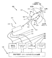
この装置はさらに、細胞の電気的活動、たとえば心電図に現れる活動のマッピングを行うように構成された、1つまたは複数のカテーテルの中に含まれる複数電極からマッピング情報を受信する第一の受信機を備える。これらの電極は患者の心臓の心腔の中に留置される。この装置はさらに、解剖学的情報を受信する第二の受信機を含む。解剖学的情報は、全体的な心臓モデル、より好ましくは組織の形態および、患者自身の心臓から記録されるその他の解剖学的情報であってもよい。双極子密度モジュールが、双極子密度d(y)のデータベースをテーブルの形で作成し、yは心組織上の、その特定の双極子密度を有する三次元位置を表す。心腔内の別のさまざまな位置xにおける、V(x)で表される電位が複数電極によって記録される。立体角ω(x,y)は、位置x(心腔内の電極の位置)とy(心腔壁上の三角形の位置)の間の投影三角形の立体角を表す。双極子密度モジュールは、心腔壁への個々の投影三角形の双極子密度を以下に基づいて測定する。すなわち、位置yにおける各投影三角形について、ω(x,y)に双極子密度d(y)を乗じたものが地点xにおける電位V(x)となる。 The apparatus further includes a first receiver for receiving mapping information from a plurality of electrodes included in one or more catheters configured to perform mapping of cellular electrical activity, eg, activity appearing in an electrocardiogram Is provided. These electrodes are placed in the heart chamber of the patient's heart. The apparatus further includes a second receiver that receives the anatomical information. The anatomical information may be an overall heart model, more preferably tissue morphology and other anatomical information recorded from the patient's own heart. The dipole density module creates a database of dipole densities d (y) in the form of a table, where y represents the three-dimensional position on the heart tissue that has that particular dipole density. Potentials represented by V (x) at different locations x in the heart chamber are recorded by multiple electrodes. The solid angle ω (x, y) represents the solid angle of the projected triangle between the position x (the position of the electrode in the heart chamber) and y (the position of the triangle on the heart chamber wall). The dipole density module measures the dipole density of individual projected triangles onto the heart chamber wall based on: That is, for each projection triangle at the position y, the potential V (x) at the point x is obtained by multiplying ω (x, y) by the dipole density d (y).
好ましい実施形態において、装置はソフトウェアプログラムを含み、たとえばパーソナルコンピュータ、ECGシステム、心組織アブレーションシステムおよび/またはイメージングシステムに組み込まれたソフトウェアプログラムがある。双極子密度モジュールで決定される三角形の数は、各投影三角形の双極子密度が比較的一定となるように十分に大きい(三角形の面積が十分に小さい)。一般には1000個またはそれ以上の三角形が計算、たとえば標準的な大きさの左心房または右心房に基づく計算に使用される。より大きな心腔には、使用される三角形の数が多くなる。 In a preferred embodiment, the device includes a software program, such as a software program embedded in a personal computer, ECG system, cardiac tissue ablation system and / or imaging system. The number of triangles determined by the dipole density module is sufficiently large (the area of the triangle is sufficiently small) so that the dipole density of each projected triangle is relatively constant. Typically 1000 or more triangles are used for calculations, eg, calculations based on standard sized left or right atrium. Larger chambers use more triangles.
他の好ましい実施形態において、患者は心臓の状態、たとえば不整脈等についての診断および/または治療を受ける。電極は1つまたは複数のマッピングカテーテルの遠位端に搭載されて、患者の心腔内に留置され、電位を記録する。イメージング機器、たとえば心臓全体のモデルを提供する機器または患者の心臓の解剖学的モデルを提供する機器は、解剖学的情報を第二の受信機に供給する。1つの実施形態において、イメージング機器は、コンピュータ断層撮影、MRI、超音波、およびマッピングカテーテル付のECGシステムのうちの1つまたは複数である。あるいは、またはこれに加えて、この装置にイメージング機器が組み込まれていてもよく、たとえば1つまたは複数の超音波センサから受信した信号から画像および距離情報を生成するように構成された超音波ユニットがある。 In other preferred embodiments, the patient is diagnosed and / or treated for a cardiac condition, such as an arrhythmia. Electrodes are mounted at the distal end of one or more mapping catheters and placed in the patient's heart chamber to record the potential. An imaging device, such as a device that provides a model of the entire heart or a device that provides an anatomical model of the patient's heart, provides anatomical information to the second receiver. In one embodiment, the imaging device is one or more of ECG systems with computed tomography, MRI, ultrasound, and mapping catheters. Alternatively, or in addition, an imaging device may be incorporated in the apparatus, for example an ultrasound unit configured to generate image and distance information from signals received from one or more ultrasound sensors There is.
他の好ましい実施形態において、双極子密度モジュールは、双極子密度のデータベースの作成を支援するように構成されたアルゴリズムを実行する。このアルゴリズムは、データベースの空間および/または時間分解能を高めるために修正または改善されるように構成された進歩的アルゴリズムであってもよい。双極子密度モジュールは、相応の時間間隔での双極子密度のマップを作成してもよい。マップを合成することにより、対応する各心拍の興奮順序のカスケードが表される。 In another preferred embodiment, the dipole density module executes an algorithm configured to assist in the creation of a dipole density database. This algorithm may be an advanced algorithm configured to be modified or improved to increase the spatial and / or temporal resolution of the database. The dipole density module may create a map of dipole density at appropriate time intervals. Combining the maps represents a cascade of excitement sequences for each corresponding heartbeat.
他の好ましい実施形態において、この装置は第三の受信機を含む。第三の受信機は、1つまたは複数の皮膚電極からマッピング情報を収集する。双極子密度モジュールは、この皮膚電極の信号を使って、後述の式により双極子密度のデータベースを計算、または再計算する。 In another preferred embodiment, the device includes a third receiver. The third receiver collects mapping information from one or more skin electrodes. The dipole density module uses the skin electrode signal to calculate or recalculate a dipole density database according to the equation described below.
本発明の他の態様によれば、患者の心臓の1つまたは複数の心腔表面における双極子密度のデータベースを作成するシステムが提供される。本発明の装置に加えて、このシステムは1つまたは複数の多電極カテーテルと、アブレーション装置と、少なくとも1つの表面または皮膚電極と、トランスデューサと、センサと、を含む。別体のイメージング機器をこのシステムの中に含めてもよい。好ましい実施形態において、マッピングカテーテルはまた、双極子密度のデータベースによって特定された組織の焼灼にも使用され、リアルタイムイメージングを使って心腔内に位置付けられる。このシステムは、リアルタイム画像と双極子密度情報、たとえば患者の心腔との相対的形状において表示される情報を表示するモニタを含む。 In accordance with another aspect of the invention, a system is provided for creating a database of dipole densities on one or more heart chamber surfaces of a patient's heart. In addition to the device of the present invention, the system includes one or more multi-electrode catheters, an ablation device, at least one surface or skin electrode, a transducer, and a sensor. A separate imaging device may be included in the system. In a preferred embodiment, the mapping catheter is also used for tissue ablation identified by a dipole density database and is positioned within the heart chamber using real-time imaging. The system includes a monitor that displays real-time images and dipole density information, such as information displayed in a relative shape with the patient's heart chamber.
本発明の他の態様によれば、患者の心臓の1つまたは複数の心腔の表面における双極子密度のデータベースを作成する方法が提供される。この方法は、複雑な不整脈疾患を診断および/または治療するために使用できる。一般的な構成では電位図波形が特定され、たとえば3つまたはそれ以上の電位図波形が特定される方法がある。好ましい実施形態において、この方法は、心房細動(AF)、心室性頻脈(VT)、心房粗動、組織瘢痕化、たとえば心腔内除細動器(ICD)が原因の組織瘢痕化の診断および/または治療に使用される。他の好ましい実施形態において、この方法は、心室虚血の検出および/または心筋機能の定量化に使用される。この方法は、複数電極のアレイを患者の心腔内に留置して、電位を測定するステップと、音センサから受信した信号を解析することによって距離または移動情報を計算するステップと、を含む。複数電極のアレイは、双極子密度を測定するために位置変更されても、されなくてもよい。 In accordance with another aspect of the present invention, a method is provided for creating a database of dipole densities at the surface of one or more heart chambers of a patient's heart. This method can be used to diagnose and / or treat complex arrhythmia diseases. In a general configuration, there is a method in which an electrogram waveform is specified, for example, three or more electrogram waveforms are specified. In a preferred embodiment, the method comprises atrial fibrillation (AF), ventricular tachycardia (VT), atrial flutter, tissue scarring, eg, tissue scarring due to intracardiac defibrillator (ICD). Used for diagnosis and / or treatment. In other preferred embodiments, the method is used for detection of ventricular ischemia and / or quantification of myocardial function. The method includes placing an array of electrodes in a patient's heart chamber to measure a potential and calculating distance or movement information by analyzing a signal received from a sound sensor. The array of multiple electrodes may or may not be repositioned to measure the dipole density.
他の好ましい実施形態において、この方法はさらに、1つまたは複数の皮膚電極を設置するステップを含む。皮膚電極により記録される情報は、双極子密度のデータベースの作成に使用される。また別の実施形態では、この方法はさらに、組織厚さ情報を計算するステップを含む。 In another preferred embodiment, the method further comprises the step of installing one or more skin electrodes. Information recorded by the skin electrode is used to create a database of dipole densities. In yet another embodiment, the method further includes calculating tissue thickness information.
本発明の他の態様によれば、患者の心腔に関する電気的および解剖学的情報を取得するための医学的方法が開示される。第一のステップで、使用者は装置をデリバリシステムの中に挿入できる。装置は上述の装置のいずれでもよい。次のステップで、使用者は装置を、デリバリシステムを通じて心腔内へと前進させることができる。次のステップで、装置および/またはデリバリシステムを操向し、装置の遠位端が心腔のほぼ幾何学中心に位置付けられるようにすることができる。装置が心腔内に位置付けられると、本明細書で開示される測定と方法に従って測定データを取得し、解析してもよい。 In accordance with another aspect of the present invention, a medical method for obtaining electrical and anatomical information about a patient's heart chamber is disclosed. In the first step, the user can insert the device into the delivery system. The device may be any of the devices described above. In the next step, the user can advance the device through the delivery system and into the heart chamber. In the next step, the device and / or delivery system can be steered so that the distal end of the device is positioned approximately at the geometric center of the heart chamber. Once the device is positioned within the heart chamber, measurement data may be acquired and analyzed according to the measurements and methods disclosed herein.
本発明の他の態様によれば、組織の診断方法が開示される。好ましい方法は、電極カテーテルの遠位端を患者の1つまたは複数の心腔内に留置するステップを含み、この電極カテーテルは少なくとも1つの電極と少なくとも1つの超音波素子を備える。次のステップで、組織の運動等の解剖学的情報が少なくとも1つの超音波素子を介して測定されてもよい。次のステップで、組織の電荷が少なくとも1つの電極を介して測定されてもよい。最後に、組織の運動と電荷の情報を解析することによって、組織の健全性が判断されてもよい。 According to another aspect of the invention, a method for diagnosing tissue is disclosed. A preferred method includes placing the distal end of an electrode catheter in one or more heart chambers of a patient, the electrode catheter comprising at least one electrode and at least one ultrasound element. In the next step, anatomical information such as tissue motion may be measured via the at least one ultrasound element. In the next step, tissue charge may be measured via at least one electrode. Finally, tissue health may be determined by analyzing tissue motion and charge information.
たとえば、適当な電気的活動を示す電気的情報と適当な組織運動を示す解剖学的情報は、健全な組織の存在と相関する。これに加えて、適当な電気的活動に示す電気的情報と不適当な組織運動を示す解剖学的情報は、虚血組織または仮死状態の組織のうちの少なくとも一方の存在と相関する。逆に、不適当な電気的活動を示す電気的情報と不適当な組織運動を示す解剖学的情報は、瘢痕化組織の存在と相関する。これに加えて、不適当な電気的活動を示す電気的情報と不適当な組織運動を示す解剖学的情報は、完全焼灼、たとえば不整脈治療のために施行される心臓のアブレーションで行われる焼灼と相関する。いくつかの実施形態において、完全焼灼は貫壁性焼灼を含む。 For example, electrical information indicating proper electrical activity and anatomical information indicating proper tissue motion correlate with the presence of healthy tissue. In addition, electrical information indicative of appropriate electrical activity and anatomical information indicative of inappropriate tissue motion correlate with the presence of at least one of ischemic tissue or asphyxia tissue. Conversely, electrical information indicating inappropriate electrical activity and anatomical information indicating inappropriate tissue motion correlate with the presence of scarred tissue. In addition, electrical information indicating improper electrical activity and anatomical information indicating improper tissue movement may result in complete ablation, such as ablation performed during cardiac ablation performed for arrhythmia treatment. Correlate. In some embodiments, complete cautery comprises transmural cautery.
より詳しくは、以下の4つのケースが存在しうる。
ケース1:電気的および解剖学的情報が適当−組織は健全である。
ケース2:電気的情報が適当で解剖学情報が不適当−組織に損傷がある。
ケース3:電気的情報が不適当で解剖学情報が適当−組織に損傷がある。
ケース4:電気的および解剖学情報がどちらも不適当−組織壊死がある。
More specifically, the following four cases can exist.
Case 1: Electrical and anatomical information is appropriate-tissue is healthy.
Case 2: Electrical information is appropriate and anatomical information is incorrect-tissue is damaged.
Case 3: Inadequate electrical information and adequate anatomy information-tissue is damaged.
Case 4: Both electrical and anatomical information are incorrect-there is tissue necrosis.
心臓のいずれか1つの領域の電気的機能の適当性を判断する実際の閾値は、興奮パターンの協調度と活性化細胞の質量等、多くの要素に依存する。これに加えて、この閾値は、各心腔によっても、患者の体の大小によっても異なる。たとえば0.5mVの閾値が適切であるかもしれず、この場合、閾値0.5mV未満の電位は不適当な電気的機能を示すかもしれず、0.5mV以上の電位は適当な電気的機能を示すかもしれない。 The actual threshold for determining the appropriateness of the electrical function of any one region of the heart depends on many factors, such as the degree of coordination of the excitation pattern and the mass of activated cells. In addition, this threshold varies with each heart chamber and with the patient's body size. For example, a threshold of 0.5 mV may be appropriate, in which case a potential below the threshold of 0.5 mV may indicate an inappropriate electrical function, and a potential above 0.5 mV may indicate an appropriate electrical function. unknown.
組織診断に含まれるものとして、医師は心細胞の電気的完全性を評価してもよい。たとえば、心細胞の機能的状態が評価されてもよい。 As included in the tissue diagnosis, the physician may assess the electrical integrity of the heart cells. For example, the functional state of cardiac cells may be evaluated.
1つの実施形態において、電気的情報は双極子密度情報を含む。これに加えて、またはその代わりに、電気的情報は再分極または波面伝播速度のうちの少なくとも一方を含んでいてもよい。 In one embodiment, the electrical information includes dipole density information. Additionally or alternatively, the electrical information may include at least one of repolarization or wavefront propagation velocity.
この方法はさらに、組織診断に基づいて心組織を焼灼するステップをさらに含んでいてもよい。たとえば、解剖学的情報は、組織厚さ情報を含み、焼灼エネルギーまたは時間の少なくとも一方が、組織厚さ情報に基づいて調整される。医師は、アブレーション施行中および施行後に組織を評価して、焼灼エネルギーの印加による組織の変化を評価してもよい。たとえば、医師はまた、1つまたは複数の超音波センサから受け取った情報を、1つまたは複数の電極から受け取った双極子密度マッピング情報と共に使って組織アブレヘションの妥当性を評価することにより、たとえば長期的な患者の転帰を改善してもよい。 The method may further include ablating the cardiac tissue based on the tissue diagnosis. For example, the anatomical information includes tissue thickness information, and at least one of ablation energy or time is adjusted based on the tissue thickness information. The doctor may evaluate the tissue during and after the ablation and evaluate the change in the tissue due to the application of ablation energy. For example, a physician can also use information received from one or more ultrasound sensors, along with dipole density mapping information received from one or more electrodes, to assess the validity of tissue ablation, for example, long-term May improve the outcome of a typical patient.
本発明の1つの態様によれば、患者の1つまたは複数の心腔の表面における双極子密度d(y)と距離測定値のデータベースを作成する装置が提供される。この装置は、1つまたは複数のカテーテルに設置された複数電極と、音波を発生するように構築、構成されたトランスデューサと、音波の反射を受けるように構築、構成されたセンサと、を含む。 According to one aspect of the invention, an apparatus is provided for creating a database of dipole density d (y) and distance measurements on the surface of one or more heart chambers of a patient. The apparatus includes a plurality of electrodes placed on one or more catheters, a transducer constructed and configured to generate sound waves, and a sensor constructed and configured to receive reflections of sound waves.
各種の実施形態において、トランスデューサはセンサを含むことができる。 In various embodiments, the transducer can include a sensor.
各種の実施形態において、トランスデューサはさらに複数電極のうちの少なくとも1つを含むことができる。 In various embodiments, the transducer can further include at least one of a plurality of electrodes.
各種の実施形態において、装置はリアルタイム画像を生成するように構築、構成することができる。 In various embodiments, the device can be constructed and configured to generate real-time images.
各種の実施形態において、装置は連続画像を生成するように構築、構成することができる。 In various embodiments, the device can be constructed and configured to generate a continuous image.
各種の実施形態において、装置は患者の組織の画像を生成するように構築、構成することができる。 In various embodiments, the device can be constructed and configured to generate an image of a patient's tissue.
各種の実施形態において、画像は1つまたは複数の心腔の画像を含むことができる。 In various embodiments, the image can include an image of one or more heart chambers.
各種の実施形態において、画像は1つまたは複数の心腔の壁の画像を含むことができる。 In various embodiments, the image can include an image of one or more heart chamber walls.
各種の実施形態において、画像は複数電極のうちの少なくとも1つの付近の組織の画像を含むことができる。 In various embodiments, the image can include an image of tissue near at least one of the plurality of electrodes.
各種の実施形態において、画像は複数電極のうちの少なくとも1つの画像を含むことができる。 In various embodiments, the image can include at least one image of the plurality of electrodes.
各種の実施形態において、装置は患者の組織の運動情報を提供するように構築、構成することができる。 In various embodiments, the device can be constructed and configured to provide patient tissue motion information.
各種の実施形態において、運動情報は心臓壁運動情報を含むことができる。 In various embodiments, the motion information can include heart wall motion information.
各種の実施形態において、装置は、患者の組織の厚さ情報を提供するように構築、構成される。 In various embodiments, the device is constructed and configured to provide patient tissue thickness information.
各種の実施形態において、厚さ情報は心臓壁厚さ情報とすることができる。 In various embodiments, the thickness information can be heart wall thickness information.
各種の実施形態において、装置は複数電極のうちの少なくとも1つの画像を生成するように構築、構成することができる。 In various embodiments, the device can be constructed and configured to generate an image of at least one of the plurality of electrodes.
各種の実施形態において、装置は、複数電極のうちの少なくとも1つの付近の組織の画像をさらに生成するように構築、構成することができる。 In various embodiments, the device can be constructed and configured to further generate an image of tissue near at least one of the plurality of electrodes.
各種の実施形態において、装置は、1つまたは複数の心腔の画像をさらに生成するように構築、構成することができる。 In various embodiments, the device can be constructed and configured to further generate an image of one or more heart chambers.
各種の実施形態において、装置は距離測定データを生成するように構築、構成することができる。 In various embodiments, the device can be constructed and configured to generate distance measurement data.
各種の実施形態において、距離測定データは、複数電極のうちの少なくとも1つと心腔壁の間の距離を含むことができる。 In various embodiments, the distance measurement data can include a distance between at least one of the plurality of electrodes and the heart chamber wall.
各種の実施形態において、距離測定データは、複数電極のうちの少なくとも1つとトランスデューサまたはセンサのうちの少なくとも1つの間の距離を含むことができる。 In various embodiments, the distance measurement data can include a distance between at least one of the plurality of electrodes and at least one of the transducer or sensor.
各種の実施形態において、距離測定データは、心腔壁とトランスデューサまたはセンサのうちの少なくとも1つの間の距離を含むことができる。 In various embodiments, the distance measurement data can include a distance between the heart chamber wall and at least one of the transducer or sensor.
各種の実施形態において、装置は、センサによって記録された角度または周波数変化のうちの少なくとも1つを解析することによって距離測定データを生成するように構築、構成することができる。 In various embodiments, the device can be constructed and configured to generate distance measurement data by analyzing at least one of the angle or frequency changes recorded by the sensor.
各種の実施形態において、装置は、心腔内の複数電極のうちの少なくとも1つの位置を測定するように構築、構成することができる。 In various embodiments, the device can be constructed and configured to measure the position of at least one of the plurality of electrodes within the heart chamber.
各種の実施形態において、装置は、心腔内の複数電極のうちの少なくとも2つの位置を測定するように構築、構成することができる。 In various embodiments, the device can be constructed and configured to measure the position of at least two of the plurality of electrodes in the heart chamber.
各種の実施形態において、装置は、複数電極から受け取った距離情報をセンサから受け取った情報と組み合わせるように構築、構成することができる。 In various embodiments, the device can be constructed and configured to combine distance information received from multiple electrodes with information received from a sensor.
各種の実施形態において、装置は、組織運動情報と細胞電気信号の両方を解析することによって、組織診断情報を提供するように構築、構成することができる。 In various embodiments, the device can be constructed and configured to provide tissue diagnostic information by analyzing both tissue motion information and cellular electrical signals.
各種の実施形態において、細胞電気信号が複数電極によって記録されるようにすることができる。 In various embodiments, cellular electrical signals can be recorded by multiple electrodes.
各種の実施形態において、組織運動情報がセンサによって提供されるようにすることができる。 In various embodiments, tissue motion information can be provided by a sensor.
各種の実施形態において、組織運動情報が複数電極によってさらに提供されるようにすることができる。 In various embodiments, tissue motion information can be further provided by multiple electrodes.
各種の実施形態において、装置は心臓アブレーション処置中に組織診断情報を提供するように構築、構成することができる。 In various embodiments, the device can be constructed and configured to provide tissue diagnostic information during a cardiac ablation procedure.
各種の実施形態において、装置は、不整脈治療または機能療法の施行中に組織診断情報を提供するように構築、構成することができ、このような不整脈療法と機能療法には以下の療法、すなわちアブレーション、遺伝子治療製剤送達、心臓再同期、薬理療法等が含まれ、これらに限定されない。 In various embodiments, the device can be constructed and configured to provide tissue diagnostic information during the delivery of arrhythmia therapy or functional therapy, and such arrhythmia therapy and functional therapy include the following therapies: ablation Gene therapy product delivery, cardiac resynchronization, pharmacological therapy, and the like.
各種の実施形態において、装置は、焼灼エネルギーを組織に送達するように構築、構成することができる。 In various embodiments, the device can be constructed and configured to deliver ablation energy to tissue.
各種の実施形態において、装置は、正確なフォーカス、伝導ギャップ、または伝導チャネル位置情報を提供するように構築、構成することができる。 In various embodiments, the device can be constructed and configured to provide accurate focus, conduction gap, or conduction channel position information.
各種の実施形態において、装置は、フォーカス、伝導ギャップの境界、または伝導チャネル位置の境界の位置を1mm〜3mm以内で特定するように構築、構成することができる。 In various embodiments, the device can be constructed and configured to locate a focus, conduction gap boundary, or conduction channel position boundary within 1 mm to 3 mm.
各種の実施形態において、装置は、電位図波形で心組織の位置を提供するように構築、構成することができる。 In various embodiments, the device can be constructed and configured to provide cardiac tissue location in an electrogram waveform.
各種の実施形態において、装置は、電位図波形を含む少なくとも3つの位置を提供するように構築、構成することができる。 In various embodiments, the device can be constructed and configured to provide at least three locations that include electrogram waveforms.
各種の実施形態において、装置は、不整脈の1心拍マッピングを提供するように構築、構成することができる。 In various embodiments, the device can be constructed and configured to provide a single heart rate mapping of the arrhythmia.
各種の実施形態において、装置は、操向および/または案内されるように構築、構成された少なくとも1つのカテーテルを備えることができる。 In various embodiments, the device can comprise at least one catheter constructed and configured to be steered and / or guided.
各種の実施形態において、カテーテルは、リアルタイム組織解析とイメージングによって電位図波形の部位まで操向および/または案内されるように構築、構成することができる。 In various embodiments, the catheter can be constructed and configured to be steered and / or guided to the site of the electrogram waveform by real-time tissue analysis and imaging.
各種の実施形態において、装置はさらにデリバリシースを備えることができる。 In various embodiments, the device can further comprise a delivery sheath.
各種の実施形態において、デリバリシースは、アブレーションカテーテルを摺動可能に受けるように構築、構成することができる。 In various embodiments, the delivery sheath can be constructed and configured to slidably receive the ablation catheter.
各種の実施形態において、装置はさらに、近位端を有する近位部と遠位端を有する遠位部を含み、患者の体内に挿入されるように構築、構成された長いシャフトを備えることができる。 In various embodiments, the device further comprises a long shaft including a proximal portion having a proximal end and a distal portion having a distal end and constructed and configured to be inserted into a patient's body. it can.
各種の実施形態において、装置はさらに、長いシャフトに着脱可能に取り付けられ、振動エネルギーを伝送するように構築、構成されたクランプアセンブリを備えることができる。 In various embodiments, the apparatus can further comprise a clamp assembly removably attached to the long shaft and constructed and configured to transmit vibration energy.
各種の実施形態において、クランプアセンブリは、超音波を発生するように構成された振動トランスデューサを備えることができる。 In various embodiments, the clamp assembly can include a vibration transducer configured to generate ultrasound.
各種の実施形態において、クランプアセンブリは、長いシャフトに着脱可能に取り付けられるように構築、構成されたクランプ機構を備えることができる。 In various embodiments, the clamp assembly can include a clamping mechanism constructed and configured to be removably attached to a long shaft.
各種の実施形態において、クランプアセンブリは、長いシャフトの近位部に位置付けることができる。 In various embodiments, the clamp assembly can be positioned proximal to the long shaft.
各種の実施形態において、装置はさらにハンドルを備えることができ、近位部がハンドルから10センチメートル以内にある。 In various embodiments, the device can further comprise a handle, the proximal portion being within 10 centimeters of the handle.
各種の実施形態において、長いシャフトはさらに、近位部から遠位部へと超音波を伝送するように構築、構成された導管を備えることができる。 In various embodiments, the long shaft can further comprise a conduit constructed and configured to transmit ultrasound from the proximal portion to the distal portion.
各種の実施形態において、クランプアセンブリは長いシャフトの遠位部に位置付けることができる。 In various embodiments, the clamp assembly can be positioned at the distal portion of the long shaft.
各種の実施形態において、遠位部は長いシャフトの遠位端から10センチメートル以内にあるようにすることができる。 In various embodiments, the distal portion can be within 10 centimeters of the distal end of the long shaft.
各種の実施形態において、装置はさらに複数電極を備えることができ、複数電極は長いシャフトの遠位端に位置付けられ、クランプアセンブリは複数電極を振動させるように構築、構成される。 In various embodiments, the device can further comprise multiple electrodes, wherein the multiple electrodes are positioned at the distal end of the long shaft and the clamp assembly is constructed and configured to vibrate the multiple electrodes.
各種の実施形態において、複数電極は上述の複数電極を含むことができる。 In various embodiments, the multiple electrodes can include the multiple electrodes described above.
各種の実施形態において、装置はさらに、長いシャフトに位置付けられた少なくとも1つのサーモカップルを備えることができ、クランプアセンブリは少なくとも1つのサーモカップルを振動させるように構築、構成される。 In various embodiments, the apparatus can further comprise at least one thermocouple positioned on the long shaft, and the clamp assembly is constructed and configured to vibrate at least one thermocouple.
各種の実施形態において、装置はさらに、長いシャフトに取り付けられる少なくとも1つの支持アームを備えることができ、クランプアセンブリは少なくとも1つの支持アームを振動させるように構築、構成される。 In various embodiments, the apparatus can further comprise at least one support arm attached to the long shaft, and the clamp assembly is constructed and configured to oscillate the at least one support arm.
各種の実施形態において、装置は、センサまたはトランスデューサのうちの少なくとも1つを有する少なくとも1つの支持アームを備えることができる。 In various embodiments, the apparatus can comprise at least one support arm having at least one of a sensor or a transducer.
各種の実施形態において、装置はさらに、長いシャフトに取り付けられた少なくとも1つのアブレーション素子を備えることができ、クランプアセンブリは少なくとも1つのアブレーション素子を振動させるように構築、構成される。 In various embodiments, the apparatus can further comprise at least one ablation element attached to the long shaft, and the clamp assembly is constructed and configured to vibrate at least one ablation element.
各種の実施形態において、装置はさらに、長いシャフトに取り付けられた少なくとも1つのセンサを備えることができ、クランプアセンブリは少なくとも1つのセンサを振動させるように構築、構成され、センサは、温度、圧力、電気信号、電極、音声およびこれらの組み合わせからなる群から選択される。 In various embodiments, the apparatus can further comprise at least one sensor attached to the long shaft, and the clamp assembly is constructed and configured to oscillate the at least one sensor, the sensor comprising temperature, pressure, It is selected from the group consisting of electrical signals, electrodes, audio and combinations thereof.
各種の実施形態において、装置はさらに、長いシャフトに取り付けられた少なくとも1つのトランスデューサを備えることができ、クランプアセンブリは少なくとも1つのトランスデューサを振動させるように構築、構成され、トランスデューサはアブレーション素子、電極、音声およびこれらの組み合わせからなる群から選択される。 In various embodiments, the apparatus can further comprise at least one transducer attached to a long shaft, and the clamp assembly is constructed and configured to vibrate at least one transducer, the transducer comprising an ablation element, an electrode, Selected from the group consisting of speech and combinations thereof.
各種の実施形態において、装置はさらに、長いシャフトに位置付けられた少なくとも1つの超音波結晶を備えることができ、クランプアセンブリは少なくとも1つの結晶を振動させるように構築、構成される。 In various embodiments, the apparatus can further comprise at least one ultrasonic crystal positioned on the long shaft, and the clamp assembly is constructed and configured to vibrate at least one crystal.
各種の実施形態において、クランプアセンブリは長いシャフトを振動させるように構築、構成することができる。 In various embodiments, the clamp assembly can be constructed and configured to vibrate a long shaft.
各種の実施形態において、クランプアセンブリは、長いシャフトの遠位端が患者の体内にある間はクランプアセンブリが患者の体外にあるように位置付けることができる。 In various embodiments, the clamp assembly can be positioned so that the clamp assembly is outside the patient's body while the distal end of the long shaft is inside the patient's body.
各種の実施形態において、センサまたはトランスデューサのうちの少なくとも一方はシャフトに留め付けられるように構築、構成することができる。 In various embodiments, at least one of the sensor or transducer can be constructed and configured to be fastened to the shaft.
各種の実施形態において、装置はシャフトを備えることができ、センサまたはトランスデューサのうちの少なくとも一方は前記装置シャフトに留め付けられるように構築、構成される。 In various embodiments, the device can comprise a shaft and at least one of the sensor or transducer is constructed and configured to be fastened to the device shaft.
各種の実施形態において、センサまたはトランスデューサのうちの少なくとも一方は、シャフトによって摺動可能に受けられるように構築、構成することができる。 In various embodiments, at least one of the sensor or transducer can be constructed and configured to be slidably received by a shaft.
各種の実施形態において、センサまたはトランスデューサのうちの少なくとも一方は、複数電極の幾何学中心に位置付けられるように構築、構成することができる。 In various embodiments, at least one of the sensors or transducers can be constructed and configured to be positioned at the geometric center of the multiple electrodes.
各種の実施形態において、センサまたはトランスデューサのうちの少なくとも一方は1つの構成要素を含むことができる。 In various embodiments, at least one of the sensor or transducer can include a single component.
各種の実施形態において、1つの構成要素は1つの結晶を含むことができる。 In various embodiments, one component can include one crystal.
各種の実施形態において、センサまたはトランスデューサのうちの少なくとも一方は、回転されるように構築、構成することができる。 In various embodiments, at least one of the sensor or transducer can be constructed and configured to be rotated.
各種の実施形態において、センサまたはトランスデューサのうちの少なくとも一方は、360°回転されるように構築、構成することができる。 In various embodiments, at least one of the sensors or transducers can be constructed and configured to be rotated 360 °.
各種の実施形態において、センサまたはトランスデューサのうちの少なくとも一方は、軸に沿って平行移動するように構築、構成することができる。 In various embodiments, at least one of the sensor or transducer can be constructed and configured to translate along an axis.
各種の実施形態において、センサまたはトランスデューサのうちの少なくとも一方は、構成要素のアレイを含むことができる。 In various embodiments, at least one of the sensor or transducer can include an array of components.
各種の実施形態において、アレイは超音波結晶のアレイを含むことができる。 In various embodiments, the array can include an array of ultrasonic crystals.
各種の実施形態において、アレイは円周アレイを含むことができる。 In various embodiments, the array can include a circumferential array.
各種の実施形態において、センサまたはトランスデューサのうちの少なくとも一方は、複数電極のうちの少なくとも1つの中またはその付近に位置付けることができる。 In various embodiments, at least one of the sensor or transducer can be located in or near at least one of the plurality of electrodes.
各種の実施形態において、センサまたはトランスデューサのうちの少なくとも一方は第一の構成要素と第二の構成要素を含むことができ、第一の構成要素は複数電極のうちの第一の電極の中またはその付近に取り付けられ、第二の構成要素は複数電極のうちの第二の電極の中またはその付近に取り付けられる。 In various embodiments, at least one of the sensor or transducer can include a first component and a second component, wherein the first component is in the first electrode of the plurality of electrodes or The second component is attached in or near the second electrode of the plurality of electrodes.
各種の実施形態において、センサまたはトランスデューサの少なくとも一方は圧電フィルムを含むことができる。 In various embodiments, at least one of the sensor or transducer can include a piezoelectric film.
各種の実施形態において、装置はさらに、第一の電極に電気的に接続されたワイヤを備えることができ、圧電フィルムは前記ワイヤの少なくとも一部を覆う。 In various embodiments, the device can further comprise a wire electrically connected to the first electrode, and the piezoelectric film covers at least a portion of the wire.
各種の実施形態において、センサまたはトランスデューサのうちの少なくとも一方は圧電ケーブルを備えることができる。 In various embodiments, at least one of the sensor or transducer can comprise a piezoelectric cable.
各種の実施形態において、装置は多アームアセンブリを含むことができ、センサまたはトランスデューサのうちの少なくとも一方は多アームアセンブリに取り付けられる。 In various embodiments, the device can include a multi-arm assembly and at least one of the sensor or transducer is attached to the multi-arm assembly.
各種の実施形態において、複数電極のうちの第一の電極は多アームアセンブリに取り付けることができる。 In various embodiments, the first of the plurality of electrodes can be attached to a multi-arm assembly.
各種の実施形態において、センサまたはトランスデューサのうちの少なくとも一方は複数電極のうちの少なくとも1つの電極と一体とすることができる。 In various embodiments, at least one of the sensor or transducer can be integral with at least one of the plurality of electrodes.
各種の実施形態において、センサまたはトランスデューサの少なくとも一方は第一の面を含むことができ、複数電極のうちの少なくとも1つの電極は第二の面を含むことができ、第一の面と第二の面は平行である。 In various embodiments, at least one of the sensor or transducer can include a first surface, and at least one electrode of the plurality of electrodes can include a second surface, the first surface and the second surface. The planes of are parallel.
各種の実施形態において、センサまたはトランスデューサのうちの少なくとも一方は、回転し、心腔との信号の送受信を行うように構築、構成することができる。 In various embodiments, at least one of the sensors or transducers can be constructed and configured to rotate and send and receive signals to and from the heart chamber.
各種の実施形態において、トランスデューサは超音波トランスデューサを含むことができる。 In various embodiments, the transducer can include an ultrasonic transducer.
各種の実施形態において、トランスデューサは、持続的またはパルス励起のいずれかの少なくとも一方で音波を生成するように構築、構成することができる。 In various embodiments, the transducer can be constructed and configured to generate sound waves at least in either continuous or pulsed excitation.
各種の実施形態において、トンラスデューサは複数のトランスデューサを含むことができる。 In various embodiments, the tonula reducer can include multiple transducers.
各種の実施形態において、トランスデューサは3MHzから18MHzの間の周波数で信号を生成することができる。 In various embodiments, the transducer can generate a signal at a frequency between 3 MHz and 18 MHz.
各種の実施形態において、トランスデューサはシャフトに留め付けられるように構築、構成することができる。 In various embodiments, the transducer can be constructed and configured to be fastened to the shaft.
各種の実施形態において、装置はさらにシャフトを備えることができ、トランスデューサは前記装置シャフトに留め付けられるように構築、構成される。 In various embodiments, the device can further comprise a shaft, and the transducer is constructed and configured to be fastened to the device shaft.
各種の実施形態において、センサは超音波センサを含むことができる。 In various embodiments, the sensor can include an ultrasonic sensor.
各種の実施形態において、センサは複数のセンサを含むことができる。 In various embodiments, the sensor can include multiple sensors.
各種の実施形態において、センサはシャフトに留め付けられるように構築、構成することができる。 In various embodiments, the sensor can be constructed and configured to be fastened to the shaft.
各種の実施形態において、装置はシャフトを備えることができ、センサは前記装置シャフトに留め付けられるように構築、構成される。 In various embodiments, the device can comprise a shaft and the sensor is constructed and configured to be secured to the device shaft.
各種の実施形態において、装置はさらに、複数電極からのマッピング情報を受け取るように構築、構成された第一の受信機であって、マッピング情報は複数電極が1つまたは複数の心腔内に留置された時に受け取られるような第一の受信機と、双極子密度d(y)の三次元データベースを生成するように構成、配置された双極子密度モジュールと、を備えることができ、双極子密度モジュールは心腔壁への個々の投影三角形についての双極子密度を測定し、位置yにおける各投影三角形について、ω(x,y)に双極子密度d(y)を乗じたものが地点xにおける電位V(x)となる。ここで、ω(x,y)はその投影三角形の立体角であり、a)xは1つまたは複数の心腔内の一連の位置を表し、b)V(x)は点xにおける測定電位であり、前記測定電位は複数電極によって記録される。 In various embodiments, the apparatus is further a first receiver constructed and configured to receive mapping information from multiple electrodes, wherein the mapping information is placed in one or more heart chambers. A dipole density module, and a dipole density module configured and arranged to generate a three-dimensional database of dipole densities d (y). The module measures the dipole density for each projection triangle on the heart chamber wall, and for each projection triangle at position y, ω (x, y) multiplied by the dipole density d (y) is at point x. The potential is V (x). Where ω (x, y) is the solid angle of the projected triangle, a) x represents a series of positions within one or more heart chambers, and b) V (x) is the measured potential at point x. And the measured potential is recorded by a plurality of electrodes.
各種の実施形態において、装置はさらに、1つまたは複数の心腔の形状図を生成するように構成された少なくとも1つのイメージング機器から解剖学的情報を受け取るように構築、構成された第二の受信機を含む。 In various embodiments, the apparatus is further configured and configured to receive anatomical information from at least one imaging device configured to generate one or more heart chamber shapes. Including receiver.
各種の実施形態において、前記投影三角形は、各投影三角形に関する双極子密度が実質的に一定となるような大きさとすることができる。 In various embodiments, the projected triangles can be sized such that the dipole density for each projected triangle is substantially constant.
各種の実施形態において、双極子密度は少なくとも1000個の投影三角形について測定することができる。 In various embodiments, the dipole density can be measured for at least 1000 projected triangles.
各種の実施形態において、双極子密度は、多数の投影三角形によって測定でき、前記数は心腔の大きさによって決まる。 In various embodiments, the dipole density can be measured by a number of projected triangles, the number depending on the size of the heart chamber.
各種の実施形態において、複数電極は1つのカテーテル内に含めることができる。 In various embodiments, multiple electrodes can be included in a single catheter.
各種の実施形態において、複数電極は2つまたはそれ以上のカテーテル内に含めることができる。 In various embodiments, multiple electrodes can be included in two or more catheters.
各種の実施形態において、イメージング機器は、コンピュータ断層撮影(CT)機器、磁気共鳴画像形成(MRI)機器、超音波機器、多電極マッピングカテーテルとマッピングシステム、およびこれらの組み合わせからなる群から選択することができる。 In various embodiments, the imaging equipment is selected from the group consisting of computed tomography (CT) equipment, magnetic resonance imaging (MRI) equipment, ultrasound equipment, multi-electrode mapping catheters and mapping systems, and combinations thereof. Can do.
各種の実施形態において、イメージング機器は、双極子密度モジュールにアップロードされる標準的な解剖学的形状を有することができる。 In various embodiments, the imaging device can have a standard anatomical shape uploaded to the dipole density module.
各種の実施形態において、双極子密度モジュールは、コンピュータ、電子モジュール、メモリの中に保存され、プロセッサにより実行可能なコンピュータプログラム、マイクロコントローラ、マイクロプロセッサ、およびこれらの組み合わせのうちの1つまたは複数を含む数学的処理素子を含むことができる。 In various embodiments, the dipole density module includes one or more of a computer program, a microcontroller, a microprocessor, and combinations thereof stored in a computer, electronic module, memory, and executable by the processor. A mathematical processing element may be included.
各種の実施形態において、双極子密度モジュールは、双極子密度d(y)のデータベースの空間分解能と時間分解能のうちの少なくとも一方を改善するように構成された進歩的アルゴリズムを実行するように構成することができる。 In various embodiments, the dipole density module is configured to execute an advanced algorithm configured to improve at least one of a spatial resolution and a temporal resolution of a database of dipole densities d (y). be able to.
各種の実施形態において、双極子密度モジュールは、双極子密度d(y)のデータベースを作成するために線形方程式系を使用することができる。 In various embodiments, the dipole density module can use a system of linear equations to create a database of dipole densities d (y).
各種の実施形態において、双極子密度モジュールは、対応する時間間隔の双極子密度d(y)のマップを作成するように構成することができる。 In various embodiments, the dipole density module can be configured to create a map of the dipole density d (y) for the corresponding time interval.
各種の実施形態において、双極子密度モジュールは、一連の心拍から、各々の対応する心拍の興奮順序のカスケードを表す合成マップを生成するように構成される。 In various embodiments, the dipole density module is configured to generate a composite map representing a cascade of excitation sequences of each corresponding heart beat from a series of heart beats.
各種の実施形態において、多数の測定電位V(x)は100,000個の電位V(x)までの範囲とすることができる。 In various embodiments, the multiple measured potentials V (x) can range up to 100,000 potentials V (x).
各種の実施形態において、心臓壁は複数の領域に分割することができ、各領域は各電極に関する領域立体角によって表され、各領域立体角はその領域内の個々の三角形の立体角の総和である。 In various embodiments, the heart wall can be divided into a plurality of regions, each region represented by a region solid angle for each electrode, and each region solid angle is the sum of solid angles of individual triangles within that region. is there.
各種の実施形態において、双極子密度d(y)を測定するために使用される領域の数は心臓壁上の100,000個の領域までの範囲とすることができる。 In various embodiments, the number of regions used to measure the dipole density d (y) can range up to 100,000 regions on the heart wall.
各種の実施形態において、測定電位V(x)を補間して領域の数を増やすことができる。 In various embodiments, the number of regions can be increased by interpolating the measured potential V (x).
各種の実施形態において、V(x)はスプラインを用いて補間することができる。 In various embodiments, V (x) can be interpolated using splines.
各種の実施形態において、装置はさらに、1つまたは複数の皮膚電極からマッピング情報を受け取るように構成された第三の受信機を備えることができる。 In various embodiments, the apparatus can further comprise a third receiver configured to receive mapping information from one or more skin electrodes.
各種の実施形態において、双極子密度モジュールは、1つまたは複数の皮膚電極からの前記マッピング情報を使用して、双極子密度d(y)のデータベースを計算および/または再計算することができる。 In various embodiments, the dipole density module can calculate and / or recalculate a database of dipole densities d (y) using the mapping information from one or more skin electrodes.
各種の実施形態において、双極子密度モジュールは、次式のうちの少なくとも1つを使って双極子密度d(y)を計算および/または再計算することができる:

各種の実施形態において、双極子密度モジュールは、正規化手法を使って式(2)と(3)を解くように構成することができる。 In various embodiments, the dipole density module can be configured to solve equations (2) and (3) using a normalization technique.
各種の実施形態において、正規化手法はTikhonov正規化法を含むことができる。 In various embodiments, the normalization technique can include a Tikhonov normalization method.
本発明の他の態様によれば、患者の1つまたは複数の心腔の表面における双極子密度d(y)と距離測定値のデータベースを作成するシステムが提供される。このシステムは、患者の1つまたは複数の心腔の表面における双極子密度d(y)のデータベースを作成する装置を含み、これは、1つまたは複数のカテーテル上に設置された複数電極と、複数電極からマッピング情報を受け取るように構成された第一の受信機であって、マッピング情報が、複数電極が1つまたは複数の心腔に留置された時に受け取られるような第一の受信機と、1つまたは複数の心腔の幾何学表現を生成するように構成された少なくとも1つのイメージング機器から解剖学的情報を受け取るように構成された第二の受信機と、双極子密度d(y)のデータベースを生成するように構成された双極子密度モジュールと、を備え、双極子密度モジュールは、心腔壁への個々の投影三角形に関する双極子密度を測定し、位置yにおける各投影三角形について、ω(x,y)に双極子密度d(y)を乗じたものが点xにおける電位V(x)となり、ω(x,y)はその投影三角形に関する立体角であり、a)xは1つまたは複数の心腔内の一連の位置を表し、b)V(x)は点xでの測定電位であり、前記測定電位は複数電極により記録される。 In accordance with another aspect of the invention, a system is provided for creating a database of dipole density d (y) and distance measurements on the surface of one or more heart chambers of a patient. The system includes a device that creates a database of dipole densities d (y) at the surface of one or more heart chambers of a patient, comprising a plurality of electrodes placed on one or more catheters, A first receiver configured to receive mapping information from a plurality of electrodes, wherein the mapping information is received when the plurality of electrodes are placed in one or more heart chambers; A second receiver configured to receive anatomical information from at least one imaging device configured to generate a geometric representation of one or more heart chambers; and a dipole density d (y A dipole density module configured to generate a database of), wherein the dipole density module measures the dipole density for each projected triangle onto the heart chamber wall and at position y For each projected triangle, the product of ω (x, y) and the dipole density d (y) is the potential V (x) at point x, where ω (x, y) is the solid angle for that projected triangle. A) x represents a series of positions in one or more heart chambers; b) V (x) is the measured potential at point x, which is recorded by multiple electrodes.
各種の実施形態において、システムはさらに第二のイメージング機器を備えることができる。 In various embodiments, the system can further comprise a second imaging device.
各種の実施形態において、システムはマッピングおよびアブレーション用カテーテルを備えることができる。 In various embodiments, the system can include a mapping and ablation catheter.
各種の実施形態において、システムは、高周波(RF)エネルギー、超音波エネルギー、極低温エネルギーのうちの1つまたは複数を供給するように構成されたアブレーション装置を備えることができる。 In various embodiments, the system can include an ablation device configured to provide one or more of radio frequency (RF) energy, ultrasonic energy, cryogenic energy.
各種の実施形態において、システムは以下の療法、すなわち遺伝子治療製剤送達、心臓再同期、薬理療法のうちの1つまたは複数を提供するように構成された装置を備えることができる。 In various embodiments, the system can comprise a device configured to provide one or more of the following therapies: gene therapy formulation delivery, cardiac resynchronization, pharmacotherapy.
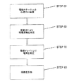
本発明の他の態様によれば、患者の1つまたは複数の心腔の表面における双極子密度d(y)と距離測定値のデータベースを作成する方法が提供される。この方法は、電極カテーテルの遠位端を患者の1つまたは複数の心腔のうちの1つの中に留置するステップと、1つまたは複数のカテーテルに設置された複数電極からマッピング情報を受け取る第一の受信機であって、マッピング情報は複数電極が1つまた複数の心腔内に留置された時に受け取られるような第一の受信機と、1つまたは複数の心腔内の幾何学的表現を生成するように構成された少なくとも1つのイメージング機器から解剖学的情報を受け取る第二の受信機と、双極子密度d(y)のデータベースを生成する双極子密度モジュールと、によって双極子密度d(y)を生成するステップであって、双極子密度モジュールが心腔壁への個々の投影三角形に関する双極子密度を測定し、位置yにおける各投影三角形について、ω(x,y)に双極子密度d(y)を乗じたものが点xにおける電位V(x)となり、ω(x,y)はその投影三角形に関する立体角であり、a)xは1つまたは複数の心腔内の一連の位置を表し、b)V(x)は点xでの測定電位であり、前記測定電位は複数電極により記録されるようなステップと、音センサから受け取った信号を解析することによって距離または移動情報を計算するステップと、を含む。 In accordance with another aspect of the invention, a method is provided for creating a database of dipole density d (y) and distance measurements on the surface of one or more heart chambers of a patient. The method includes placing a distal end of an electrode catheter in one of one or more heart chambers of a patient and receiving mapping information from multiple electrodes placed on the one or more catheters. A first receiver such that the mapping information is received when the electrodes are placed in one or more heart chambers and the geometry in the one or more heart chambers. A dipole density by a second receiver for receiving anatomical information from at least one imaging device configured to generate a representation, and a dipole density module for generating a database of dipole densities d (y) generating d (y), wherein the dipole density module measures the dipole density for each projection triangle on the heart chamber wall, and for each projection triangle at position y, ω (x Multiplying y) by the dipole density d (y) gives the potential V (x) at point x, ω (x, y) is the solid angle for that projected triangle, and a) x is one or more B) V (x) is the measured potential at point x, where the measured potential is recorded by multiple electrodes, and the signal received from the sound sensor is analyzed Calculating distance or movement information.
各種の実施形態において、方法は、組織厚さ情報を計算するステップを含む、距離情報を計算するステップを含むことができる。 In various embodiments, the method can include calculating distance information, including calculating tissue thickness information.
各種の実施形態において、方法は、双極子密度d(y)を使って、心臓の異常な電気的活動の発生源の位置を特定するステップを含むことができる。 In various embodiments, the method can include using the dipole density d (y) to locate the source of abnormal electrical activity in the heart.
各種の実施形態において、双極子密度を計算するステップは、プロセッサがメモリ内に記憶されたコンピュータプログラムを実行するステップを含むことができ、コンピュータプログラムはメモリ内の双極子密度のテーブルを生成するためのアルゴリズムを具体化する。 In various embodiments, the step of calculating the dipole density may include the step of the processor executing a computer program stored in the memory, the computer program generating a table of dipole densities in the memory. The algorithm of is materialized.
本発明の他の態様によれば、組織の診断方法が提供され、前記方法は、患者の1つまたは複数の心腔内にカテーテルの遠位端を留置するステップであって、カテーテルが少なくとも1つの電極と少なくとも1つの超音波素子を含むようなステップと、その少なくとも1つの超音波素子を介して組織の運動を測定するステップと、少なくとも1つの電極を介して電荷を測定するステップと、組織の運動と電荷に基づいて組織の診断を下すステップと、を含む。 According to another aspect of the invention, a method for tissue diagnosis is provided, the method comprising placing a distal end of a catheter within one or more heart chambers of a patient, wherein the catheter is at least one. Including one electrode and at least one ultrasonic element; measuring tissue movement via the at least one ultrasonic element; measuring charge via the at least one electrode; Making a tissue diagnosis based on the movement and charge of the tissue.
本発明の他の態様によれば、医学的方法が提供され、これは、特許請求の範囲の請求項1〜122のいずれか1項に記載の装置をデリバリシステム内に挿入するステップと、装置を、デリバリシステムを通じて心腔へと前進させるステップと、装置および/またはデリバリシステムを、装置の遠位端が心腔のほぼ幾何学中心に位置付けられるように操向するステップと、を含む。 According to another aspect of the present invention there is provided a medical method comprising inserting the device according to any one of claims 1 to 122 into a delivery system; And advancing the device and / or delivery system through the delivery system such that the distal end of the device is positioned approximately at the geometric center of the heart chamber.
本発明の他の態様によれば、患者の組織の診断方法が提供され、これは、電気的情報と解剖学的情報を組み合わせるステップを含み、電気的情報は、組織によって生成される電気信号を記録するように構築、構成された複数電極から受け取られる情報を含み、解剖学的情報は、音声信号を記録するように構築、構成されたセンサによって受け取られる情報を含む。 In accordance with another aspect of the present invention, a method for diagnosing a patient's tissue is provided that includes combining electrical information and anatomical information, wherein the electrical information comprises an electrical signal generated by the tissue. Anatomical information includes information received by a sensor configured and configured to record audio signals, including information received from multiple electrodes configured and configured to record.
各種の実施形態において、適当な電気的活動を示す電気信号と適当な組織の運動を示す解剖学的情報は、健全な組織の存在と相関しうる。 In various embodiments, electrical signals indicative of proper electrical activity and anatomical information indicative of proper tissue motion can be correlated with the presence of healthy tissue.
各種の実施形態において、適当な電気的活動を示す電気信号と不適当な組織の運動を示す解剖学的情報は、虚血組織または仮死組織のうちの少なくとも一方の存在と相関しうる。 In various embodiments, electrical signals indicative of appropriate electrical activity and anatomical information indicative of inappropriate tissue motion may be correlated with the presence of at least one of ischemic tissue or asphyxia tissue.
各種の実施形態において、電気的情報は閾値電圧より大きい信号を含むことができる。 In various embodiments, the electrical information can include a signal that is greater than a threshold voltage.
各種の実施形態において、不適当な電気的活動を示す電気的情報と不適当な組織運動を示す解剖学的情報は、瘢痕化組織の存在と相関しうる。 In various embodiments, electrical information indicative of inappropriate electrical activity and anatomical information indicative of inappropriate tissue motion may be correlated with the presence of scarred tissue.
各種の実施形態において、診断は組織虚血の評価を含むことができる。 In various embodiments, the diagnosis can include an assessment of tissue ischemia.
各種の実施形態において、診断は心細胞の電気的完全性の評価を含む。 In various embodiments, the diagnosis includes an assessment of cardiac cell electrical integrity.
各種の実施形態において、診断はさらに、心細胞の機能的状態の評価を含むことができる。 In various embodiments, the diagnosis can further include an assessment of the functional state of the heart cells.
各種の実施形態において、不適当な電気的活動を示す電気的情報と不適当な組織運動を示す解剖学的情報は、不整脈の治療のために施行された心臓のアブレーションにおいて行われた焼灼のような完全焼灼の存在と相関しうる。 In various embodiments, electrical information indicative of improper electrical activity and anatomical information indicative of improper tissue motion may be similar to ablation performed during cardiac ablation performed for arrhythmia treatment. It can correlate with the presence of complete shochu.
各種の実施形態において、完全焼灼は貫壁性焼灼を含むことができる。 In various embodiments, complete cautery can include transmural cautery.
各種の実施形態において、電気的情報は双極子密度情報を含むことができる。 In various embodiments, the electrical information can include dipole density information.
各種の実施形態において、電気的情報は、脱分極、再分極、波面伝搬速度、電圧の大きさ(最大、最小、勾配)、興奮のタイミング、興奮持続時間のうちの少なくとも1つを含むことができる。 In various embodiments, the electrical information may include at least one of depolarization, repolarization, wavefront propagation velocity, voltage magnitude (maximum, minimum, slope), excitement timing, excitement duration. it can.
各種の実施形態において、方法はさらに、ある時間にわたって焼灼エネルギーを印加することによって心組織を焼灼するステップをさらに含むことができる。 In various embodiments, the method can further include ablating the cardiac tissue by applying ablation energy over a period of time.
各種の実施形態において、解剖学的情報は組織厚さ情報を含むことができ、焼灼エネルギーと時間の少なくとも一方は組織厚さ情報に基づいて調整される。 In various embodiments, the anatomical information can include tissue thickness information, and at least one of ablation energy and time is adjusted based on the tissue thickness information.
本発明の態様によれば、患者に医療処置を施行する方法が提供され、この方法は、第一のカテーテルを患者に挿入するステップであって、第一のカテーテルが第一の素子群と少なくとも1つのセンサを含むようなステップと、第二のカテーテルを患者に挿入するステップであって、第二のカテーテルが長いシャフトを含み、第二のカテーテルが第二の素子群を含むようなステップと、クランプアセンブリを第二のカテーテルに取り付けるステップであって、クランプアセンブリが第二のカテーテルに着脱可能に取り付けられ、振動エネルギーを伝送するように構築、構成されているようなステップと、を含む。 According to an aspect of the present invention, there is provided a method of performing a medical procedure on a patient, the method comprising inserting a first catheter into the patient, the first catheter at least with the first group of elements. Including a single sensor, and inserting a second catheter into the patient, wherein the second catheter includes a long shaft and the second catheter includes a second group of elements; Attaching the clamp assembly to the second catheter, wherein the clamp assembly is removably attached to the second catheter and is constructed and configured to transmit vibrational energy.
各種の実施形態において、第一の素子群はセンサを含むことができる。 In various embodiments, the first group of elements can include a sensor.
各種の実施形態において、センサは温度、圧力、電気信号、電極、音声およびこれらの組み合わせからなる群から選択することができる。 In various embodiments, the sensor can be selected from the group consisting of temperature, pressure, electrical signal, electrode, sound, and combinations thereof.
各種の実施形態において、第一の素子群はトランスデューサを含むことができる。 In various embodiments, the first group of elements can include a transducer.
各種の実施形態において、トランスデューサはアブレーション素子、電極、音声、これらの組み合わせからなる群から選択することができる。 In various embodiments, the transducer can be selected from the group consisting of ablation elements, electrodes, sound, and combinations thereof.
各種の実施形態において、少なくとも1つのセンサは超音波センサを含むことができる。 In various embodiments, the at least one sensor can include an ultrasonic sensor.
各種の実施形態において、少なくとも1つのセンサはトランスデューサを含むことができる。 In various embodiments, the at least one sensor can include a transducer.
各種の実施形態において、トランスデューサは超音波トランスデューサを含むことができる。 In various embodiments, the transducer can include an ultrasonic transducer.
各種の実施形態において、第二の素子群はセンサを含むことができる。 In various embodiments, the second group of elements can include a sensor.
各種の実施形態において、センサは温度、圧力、電気信号、電極、音声およびこれらの組み合わせからなる群から選択することができる。 In various embodiments, the sensor can be selected from the group consisting of temperature, pressure, electrical signal, electrode, sound, and combinations thereof.
各種の実施形態において、第二の素子群はトランスデューサを含むことができる。 In various embodiments, the second group of elements can include a transducer.
各種の実施形態において、トランスデューサはアブレーション素子、電極、音声およびこれらの組み合わせからなる群から選択することができる。 In various embodiments, the transducer can be selected from the group consisting of ablation elements, electrodes, sound, and combinations thereof.
各種の実施形態において、第二のカテーテルの長いシャフトは、近位端を有する近位部と遠位端を有する遠位部を有することができる。 In various embodiments, the long shaft of the second catheter can have a proximal portion having a proximal end and a distal portion having a distal end.
各種の実施形態において、クランプアセンブリは、超音波を発生するように構成された振動トランスデューサを含むことができる。 In various embodiments, the clamp assembly can include a vibration transducer configured to generate ultrasound.
各種の実施形態において、クランプアセンブリは、第二のカテーテルの長いシャフトに着脱可能に取り付けられるように構築、構成されたクランプ機構を含むことができる。 In various embodiments, the clamp assembly can include a clamp mechanism constructed and configured to be removably attached to the long shaft of the second catheter.
各種の実施形態において、クランプアセンブリは、第二のカテーテルの長いシャフトの近位部に位置付けることができる。 In various embodiments, the clamp assembly can be positioned proximal to the long shaft of the second catheter.
各種の実施形態において、第二のカテーテルはハンドルを備えることができる。 In various embodiments, the second catheter can comprise a handle.
各種の実施形態において、クランプアセンブリはハンドルから10センチメートル以内に位置付けることができる。 In various embodiments, the clamp assembly can be positioned within 10 centimeters of the handle.
各種の実施形態において、第二のカテーテルの長いシャフトはさらに、第二のカテーテルの長いシャフトの近位部から遠位部に超音波を伝送するように構築、構成された導管を備えることができる。 In various embodiments, the second catheter long shaft may further comprise a conduit constructed and configured to transmit ultrasound from the proximal portion to the distal portion of the second catheter long shaft. .
各種の実施形態において、クランプアセンブリは第二のカテーテルの長いシャフトの遠位部に位置付けることができる。 In various embodiments, the clamp assembly can be positioned at the distal portion of the long shaft of the second catheter.
各種の実施形態において、第二のカテーテルの遠位部は第二のカテーテルの長いシャフトの遠位端から10センチメートル以内とすることができる。 In various embodiments, the distal portion of the second catheter can be within 10 centimeters of the distal end of the second catheter's long shaft.
各種の実施形態において、第二のカテーテルの長いシャフトはさらに、複数電極を備えることができ、複数電極は第二のカテーテルの長いシャフトの遠位端に位置付けられ、クランプアセンブリは複数電極を振動させるように構築、構成される。 In various embodiments, the long shaft of the second catheter can further comprise multiple electrodes, the multiple electrodes are positioned at the distal end of the long shaft of the second catheter, and the clamp assembly vibrates the multiple electrodes. Constructed and configured as follows.
各種の実施形態において、複数電極は上述のような複数電極を含むことができる。 In various embodiments, the multiple electrodes can include multiple electrodes as described above.
各種の実施形態において、第二のカテーテルの長いシャフトはさらに、第二のカテーテルの長いシャフトに位置付けられた少なくとも1つのサーモカップルを備えることができ、クランプアセンブリは少なくとも1つのサーモカップルを振動させるように構築、構成される。 In various embodiments, the long shaft of the second catheter can further comprise at least one thermocouple positioned on the long shaft of the second catheter such that the clamp assembly causes the at least one thermocouple to vibrate. Built and configured.
各種の実施形態において、第二のカテーテルの長いシャフトはさらに、第二のカテーテルの長いシャフトに取り付けられた少なくとも1つの支持アームを備えることができ、クランプアセンブリは少なくとも1つの支持アームを振動させるように構築、構成される。 In various embodiments, the long shaft of the second catheter can further comprise at least one support arm attached to the long shaft of the second catheter such that the clamp assembly causes the at least one support arm to vibrate. Built and configured.
各種の実施形態において、少なくとも1つの支持アームは、センサまたはトランスデューサのうちの少なくとも一方を含むことができる。 In various embodiments, the at least one support arm can include at least one of a sensor or a transducer.
各種の実施形態において、第二のカテーテルの長いシャフトはさらに、第二のカテーテルの長いシャフトに取り付けられた少なくとも1つのアブレーション素子を備えることができ、クランプアセンブリは少なくとも1つのアブレーション素子を振動させるように構築、構成することができる。 In various embodiments, the long shaft of the second catheter can further comprise at least one ablation element attached to the long shaft of the second catheter such that the clamp assembly vibrates at least one ablation element. Can be constructed and configured.
各種の実施形態において、第二のカテーテルの長いシャフトはさらに、第二のカテーテルの長いシャフトに取り付けられた少なくとも1つのセンサを含むことができ、クランプアセンブリは少なくとも1つのセンサを振動させるように構築、構成することができ、センサは、温度、圧力、電気信号、電極、音声およびこれらの組み合わせからなる群から選択される。 In various embodiments, the long shaft of the second catheter can further include at least one sensor attached to the long shaft of the second catheter, and the clamp assembly is configured to vibrate the at least one sensor. And the sensor is selected from the group consisting of temperature, pressure, electrical signal, electrode, sound and combinations thereof.
各種の実施形態において、第二のカテーテルの長いシャフトはさらに、第二のカテーテルの長いシャフトに取り付けられた少なくとも1つのトランスデューサを備えることができ、クランプアセンブリは少なくとも1つのトランスデューサを振動させるように構築、構成することができ、トランスデューサは、アブレーション素子、電極、音声およびこれらの組み合わせからなる群から選択される。 In various embodiments, the long shaft of the second catheter can further comprise at least one transducer attached to the long shaft of the second catheter, and the clamp assembly is configured to vibrate at least one transducer. And the transducer is selected from the group consisting of ablation elements, electrodes, audio and combinations thereof.
各種の実施形態において、第二のカテーテルの長いシャフトはさらに、第二のカテーテルの長いシャフトに位置付けられた少なくとも1つの超音波結晶を備えることができ、クランプアセンブリは少なくとも1つの結晶を振動させるように構築、構成することができる。 In various embodiments, the long shaft of the second catheter can further comprise at least one ultrasonic crystal positioned on the long shaft of the second catheter, and the clamp assembly causes the at least one crystal to vibrate. Can be constructed and configured.
各種の実施形態において、クランプアセンブリは第二のカテーテルの長いシャフトを振動させるように構築、構成することができる。 In various embodiments, the clamp assembly can be constructed and configured to vibrate the long shaft of the second catheter.
各種の実施形態において、クランプアセンブリは、第二のカテーテルの長いシャフトの遠位端が患者の体内にある間にはクランプアセンブリが患者の体外にあることができるように位置付けることができる。 In various embodiments, the clamp assembly can be positioned so that the clamp assembly can be outside the patient's body while the distal end of the second catheter's long shaft is inside the patient's body.
本願に含められた図面に描かれているような、双極子密度マッピングのために超音波を使用するリアルタイムの非接触型イメージングおよび距離測定装置、システムおよび/または方法のほか、組織の健全性の診断方法が提供される。 Real-time non-contact imaging and distance measuring devices, systems and / or methods that use ultrasound for dipole density mapping, as depicted in the drawings included in this application, as well as tissue health A diagnostic method is provided.
添付の図面は本明細書に組み込まれ、その一部をなし、本発明による各種の実施形態を示しており、説明文と併せて本発明の原理を説明するのに役立つ。 The accompanying drawings, which are incorporated in and constitute a part of this specification, illustrate various embodiments according to the invention and, together with the description, serve to explain the principles of the invention.
表面電荷密度を計算する装置は、2007年8月3日に出願された、“METHOD AND DEVICE FOR DETERMINING AND PRESENTING SURFACE CHARGE AND DIPOLE DENSITIES ON CARDIAC WALLS”と題する国際特許出願第PCT/CH2007/000380号(以下、「‘380号特許出願」という)に詳しく記載されている。 The apparatus for calculating the surface charge density is an international patent application No. 7 / PC80, which is filed on August 3, 2007, entitled “METHOD AND DEVICE FOR DETERMINING AND PRESENTING SURFACE CHARGE AND DIPOLE DENITIES ON CARDIAC WALLS”. (Hereinafter referred to as “'380 patent application”).
‘380号特許出願に記載されているように、研究の結果、表面電荷(すなわちその分布)または双極子密度(すなわちその分布)を使って分布マップを作成することにより、局所の心細胞の電気イオン活量に関して、電位より詳細で正確な情報が得られることがわかった。表面電荷または双極子密度は、電気的活動の正確で鮮鋭な情報を高い空間分解能で提供するのに対し、電荷密度の集積から得られる電位では、電気的活動の拡散的な概要しか把握できない。たんぱく質のイオン電荷と水溶性イオンを含む心細胞膜の電気的性質は、表面電荷と双極子密度によって正確に表すことができる。表面電荷密度または双極子密度は、心臓の中で直接測定することができず、測定された電位をもとに、数学的に正確に計算しなければならない。換言すれば、現在のマッピングシステムによって得られた電圧マップの情報は、これらから表面電荷密度または双極子密度を計算すれば大幅に改善できる。 As described in the '380 patent application, as a result of research, the electrical charge of local cardiac cells can be determined by creating a distribution map using surface charge (ie, its distribution) or dipole density (ie, its distribution). It was found that detailed and accurate information on the ion activity can be obtained from the potential. Surface charge or dipole density provides accurate and sharp information on electrical activity with high spatial resolution, whereas the potential resulting from charge density integration provides only a diffusive overview of electrical activity. The electrical properties of heart cell membranes, including protein ionic charge and water-soluble ions, can be accurately represented by surface charge and dipole density. The surface charge density or dipole density cannot be measured directly in the heart and must be calculated mathematically and accurately based on the measured potential. In other words, the voltage map information obtained by current mapping systems can be greatly improved by calculating the surface charge density or dipole density from them.
表面電荷密度とは、単位面積(cm2)あたりの表面電荷(クーロン)を意味する。そのため、双極子は中性元素であり、一部が正電荷、他の部分が同等であるが負の電荷を有する。双極子は細胞膜の電気的性質をよりよく表している可能性があり、これは、生物学的環境ではイオン電荷が巨視的に分離されないからである。 The surface charge density means a surface charge (coulomb) per unit area (cm 2 ). For this reason, dipoles are neutral elements, some having a positive charge and others having the same but negative charge. Dipoles may better represent the electrical properties of cell membranes because ionic charges are not macroscopically separated in a biological environment.
‘380号特許出願により表面電荷密度(表面電荷密度分布)のマップを生成するためには、ある心腔の形状を知る必要がある。心腔の3D形状は一般に、現在入手可能な一般的なマッピングシステム(いわゆるロケータシステム)によって、あるいはCT/MRIスキャンからの解剖学的データの積分によって評価される。非接触型マッピング法による電位の測定には、プローブ電極が使用された。プローブ電極は、楕円形または球形の多電極アレイであってもよい。球形は、その後のデータ解析にとって、特定の利点を有する。しかしながら、Veの測定には他の種類の電極または、複数の独立した電極でも使用できる。たとえば、心内膜内の心室内腔に関して、表面Spを有するプローブ電極を血液中に設置した場合、表面SP上の点x,y,zの電位V(x,y,z)を測定することが可能である。心内膜の表面Seの電位を計算するには、ラプラス方程式、
解は整数であり、それによって、血液が充満している心腔の全容量の中の点x’y’z’における電位V(x’y’z’)を計算することができる。前記整数を数値的に計算するために、心表面の離散化が必要であり、いわゆる境界要素法(BEM)を使用しなければならない。 The solution is an integer, whereby the potential V (x'y'z ') at the point x'y'z' in the total volume of the heart chamber filled with blood can be calculated. In order to calculate the integer numerically, a discretization of the heart surface is required and the so-called boundary element method (BEM) must be used.
境界要素法は、線形積分方程式(すなわち、面積分の形態)を解くための数値的計算方法である。この方法は、流体力学、音響学、電磁気学、破壊力学を含む工学および科学の多くの分野で応用された。 The boundary element method is a numerical calculation method for solving a linear integral equation (that is, a form of area). This method has been applied in many fields of engineering and science, including hydrodynamics, acoustics, electromagnetics, and fracture mechanics.
境界要素法は、有限要素法を含めた他の方法より効率的であることが多い。境界要素定式によれば、一般に、離散化後の完全占有行列が得られる。これは、ストレージ要件と計算時間が問題の大きさの二乗に従って増大する傾向があることを意味する。これに対して、有限要素行列は一般に帯状であり(要素は局所的にのみ接続される)、システム行列のストレージ要件は一般に、問題の大きさとともにほとんど直線的に増大する。 The boundary element method is often more efficient than other methods, including the finite element method. In general, according to the boundary element formulation, a completely occupied matrix after discretization is obtained. This means that storage requirements and computation time tend to increase with the square of the problem size. In contrast, finite element matrices are generally banded (elements are only connected locally), and the storage requirements of system matrices generally increase almost linearly with the size of the problem.
上記を鑑み、プローブの表面上のすべての電位VP(x1’y1’z1’)を測定することができる。心腔壁の電位Veを計算するには、心腔の表面の既知の形状を個別の部分に分割して、境界要素法を使用しなければならない。すると、心内膜の電位Veは、プローブの電位VP:Ve=TVPからの線形行列変換Tによって得られる。 In view of the above, all potentials V P (x1′y1′z1 ′) on the surface of the probe can be measured. To calculate the heart chamber wall potential V e , the boundary element method must be used, dividing the known shape of the surface of the heart chamber into discrete portions. The endocardial potential Ve is then obtained by a linear matrix transformation T from the probe potential V P : V e = TV P.
少なくとも1つの、ある心腔の1つまたは複数の位置P(x,y,z)における、ある時間tの心細胞の1つまたは複数の電位Veを測定し、計算した後。表面電荷密度と双極子密度は、以下の2つのポワソン方程式によって電位に関係付けられる。
![]()
![]()
![]()
![]()
心腔壁の表面上の電位Veと表面電荷(4)または双極子密度(5)の間には公知の関係がある。
境界要素法はここでも、式4と5の電位Veを所望の表面電荷密度と双極子密度に変換するためのコードを提供し、これらはデータベースに記録できる。 BEM is again provides code for converting the potential V e of formula 4 and 5 to a desired surface charge density and dipole density, it can be recorded in the database.
この方法の他の実施形態では、電位Veは接触型マッピングによって測定される。この場合、電位Veを計算するステップは不要であり、これは、電極を心腔壁に直接接触させることによって、すでに電位Veが得られるからである。 In another embodiment of this method, the potential V e is measured by contact mapping. In this case, the step of calculating the potential V e is not necessary because the potential V e is already obtained by bringing the electrode into direct contact with the heart chamber wall.
好ましい実施形態において、プローブ電極は、電位Veを正確に計算でき、それゆえ、Veを所望の電荷または双極子密度に変換するための計算を容易にするような形状を有する。電極のこの好ましい形状は基本的に楕円形または球形である。 In a preferred embodiment, the probe electrode has a shape such that the potential V e can be accurately calculated, thus facilitating calculations to convert V e to the desired charge or dipole density. This preferred shape of the electrode is basically elliptical or spherical.
‘380号特許出願に関して少なくとも1つのある心腔の表面電荷密度のデータベーステーブルを作成するための方法を採用するためには、少なくとも、
a)ある心腔の表面上のある位置P(x,y,z)における電位Vを測定し、記録する1つのユニット(接触型マッピング)または、壁と直接接触せずに心内に位置付けられたプローブ(非接触型マッピング)と、
b)測定された電位をデジタルデータに変換する1つのA/D変換器と、
c)測定および/または変換されたデータを保存する1つのメモリと、
d)デジタルデータをデジタル表面電荷密度または双極子密度データに変換する1つのプロセッサユニットと、
を含むシステムを使用することが好ましかった。
In order to employ a method for creating a database table of at least one cardiac chamber surface charge density with respect to the '380 patent application, at least:
a) One unit for measuring and recording the potential V at a position P (x, y, z) on the surface of a heart chamber (contact mapping) or positioned in the heart without direct contact with the wall Probe (non-contact mapping),
b) one A / D converter that converts the measured potential into digital data;
c) one memory for storing measured and / or converted data;
d) one processor unit that converts the digital data into digital surface charge density or dipole density data;
It was preferred to use a system containing
当業界では、ある心腔内の心細胞の電位の位置特定と測定を侵襲的および非侵襲的方法で行うための多数の装置がよく知られており、長年にわたり医療従事者によって採用されてきた。したがって、‘380号特許出願の方法、システム、装置では、本発明の最良の実践態様を実行するための特段の新たな電極は一切必要なかった。その代わりに、‘380号特許出願は入手可能なデータの新規で有利な処理を提案したものであり、これによって、心臓の表面電位のみに基づく先行技術のシステムと比較して、心臓の活動のマッピングの精密さ、正確さ、空間分解能を改善することができる。‘380号特許出願のシステムと方法はまた、代謝および機能的情報を含め、不整脈と心細胞の電気的状態を診断するための優れた診断方法を提供することができるであろう。 A number of devices are well known in the art for locating and measuring the potential of cardiac cells in a heart chamber in an invasive and non-invasive manner and have been adopted by healthcare professionals for many years. . Thus, the method, system and apparatus of the '380 patent application did not require any special new electrodes to implement the best practice of the present invention. Instead, the '380 patent application proposes a new and advantageous treatment of the available data, thereby comparing the activity of the heart as compared to prior art systems based solely on the surface potential of the heart. Mapping precision, accuracy, and spatial resolution can be improved. The system and method of the '380 patent application could also provide an excellent diagnostic method for diagnosing arrhythmia and cardiac cell electrical status, including metabolic and functional information.
本発明は、心臓壁上の双極子電荷密度の分布と活動を計算し、視覚化するための改良された装置、システム、方法を提供する。双極子密度は幾何学的に直接測定され、従来の外挿アルゴリズムを使用した場合に遭遇するエラーを避けることができる。 The present invention provides an improved apparatus, system and method for calculating and visualizing the distribution and activity of dipole charge density on the heart wall. The dipole density is directly measured geometrically to avoid errors encountered when using conventional extrapolation algorithms.
1つの実施形態において、本発明の装置は、1つまたは複数のカテーテルに設置された複数電極と、トランスデューサと、センサと、を含む。この装置は、患者の1つまたは複数の心腔の表面における双極子密度d(y)と距離の測定値の三次元データベースを作成するために使用できる。距離測定データはたとえば、複数電極のうちの少なくとも1つと心臓壁の間の距離、複数電極のうちの少なくとも1つとトランスデューサおよび/またはセンサの間の距離、心臓壁とトランスデューサおよび/またはセンサの間の距離を含んでいてもよい。距離測定データは、センサにより記録された角度および/またはセンサの周波数変化を解析することによって計算してもよい。この装置はまた、患者の組織の連続的なリアルタイム画像を生成するように構成されてもよい。画像の例としては、たとえば1つまたは複数の心腔、心臓壁、複数電極のうちの少なくとも1つの付近の組織、複数電極のうちの少なくとも1つ、およびこれらの組み合わせであってもよい。この装置は、組織の位置、組織の厚さ(たとえば、心臓壁の厚さ)および組織の運動(たとえば心臓壁の運動)の情報等の組織画像情報、組織の2点間の距離、ある組織の位置と装置の構成要素の位置の間の距離、2つの装置構成要素の位置間の距離等の距離情報、組織の電気的活動情報、組織の一部の焼灼状態、およびこれらの組み合わせのうちの1つまたは複数を提供してもよい。 In one embodiment, the device of the present invention includes multiple electrodes placed on one or more catheters, a transducer, and a sensor. This device can be used to create a three-dimensional database of dipole density d (y) and distance measurements at the surface of one or more heart chambers of a patient. The distance measurement data may be, for example, a distance between at least one of the plurality of electrodes and the heart wall, a distance between at least one of the plurality of electrodes and the transducer and / or sensor, and between the heart wall and the transducer and / or sensor. The distance may be included. The distance measurement data may be calculated by analyzing the angle recorded by the sensor and / or the frequency change of the sensor. The device may also be configured to generate a continuous real-time image of the patient's tissue. Examples of images may be, for example, one or more heart chambers, heart walls, tissue near at least one of the plurality of electrodes, at least one of the plurality of electrodes, and combinations thereof. This device provides tissue image information such as tissue location, tissue thickness (eg, heart wall thickness) and tissue motion (eg, heart wall motion) information, distance between two points of tissue, certain tissue The distance between the position of the device and the position of the component of the device, distance information such as the distance between the positions of the two device components, the electrical activity information of the tissue, the cautery state of a part of the tissue, and combinations thereof One or more of the above may be provided.
本発明はトランスデューサとセンサを取り入れ、これらは各々、好ましくは超音波式であり、1つの構成要素の中に含まれる。トランスデューサとセンサは、患者の組織または1つまたは複数のカテーテルまたはその他の装置の構成要素等の1つまたは複数の標的の距離または存在の非接触型測定を行うように構成される。情報は、超音波を送信し、その後、反響が戻ってセンサによって感知されるまでに必要な時間を測定することによって生成され、それゆえ、すべての反射面とセンサ/送信機の間の距離が測定される。この追加情報によって、より精密な双極子密度d(y)の測定が可能となる。測定は、対象物の厚さ、たとえば心組織の厚さを測定するために行ってもよく、これを使ってエネルギーの出力と供給時間等のアブレーションパラメータを決定できる。 The present invention incorporates transducers and sensors, each of which is preferably ultrasonic and is contained within a single component. The transducers and sensors are configured to make non-contact measurements of the distance or presence of one or more targets, such as patient tissue or one or more catheters or other device components. The information is generated by transmitting an ultrasonic wave and then measuring the time required for the echo to return and be sensed by the sensor, so the distance between all reflective surfaces and the sensor / transmitter is Measured. This additional information enables a more precise measurement of the dipole density d (y). Measurements may be made to measure the thickness of an object, such as the thickness of heart tissue, and can be used to determine ablation parameters such as energy output and delivery time.
本発明を利用して、組織の診断方法もまた開示される。カテーテル装置から収集される情報、特に組織の運動と組織の電荷を解析することにより、医師は組織の健全性を判断できる。たとえば、適当な組織運動が検出され、健全な状態を示す電気信号を組織が生成した場合、組織は健全であると判断される。組織の診断によって、医師はどのような治療、たとえばアブレーションがその患者にとって好ましいかを判断できる。 Utilizing the present invention, a tissue diagnostic method is also disclosed. By analyzing information collected from the catheter device, particularly tissue motion and tissue charge, a physician can determine the health of the tissue. For example, when an appropriate tissue motion is detected and the tissue generates an electrical signal indicating a healthy state, the tissue is determined to be healthy. By diagnosing the tissue, the physician can determine what treatment, for example, ablation is preferred for the patient.
本発明によれば、心臓壁上の双極子密度d(y)のデータベースを測定し、計算する装置が提供される。心臓において実際に測定される電位は、双極子とみなすことのできる細胞の電気的活動から得られる。双極子は生体膜の両側のイオン電荷からなる。双極子密度の使用によって、電気的活動の正確な表現が提供される。本発明によるシステムと方法は、1つまたは複数の数学的定理を利用して、双極子密度を効率的かつ有効に計算する。この計算は、現在のシステムによって生成される仮想的電位の計算よりずっと精密であり、現在のシステムは、必要な数値的方法と、双極子密度ではなく電位を使用することによって、空間的精度を欠く。本発明によるシステムと方法は、たとえばコンピュータシステムまたは同様のマイクロコントローラおよび/または数学的処理装置を使用する双極子密度の幾何学的な計算において効率的である。 In accordance with the present invention, an apparatus for measuring and calculating a database of dipole densities d (y) on the heart wall is provided. The potential actually measured in the heart is derived from the electrical activity of the cell, which can be considered as a dipole. A dipole consists of ionic charges on both sides of a biological membrane. The use of dipole density provides an accurate representation of electrical activity. The system and method according to the present invention utilizes one or more mathematical theorems to efficiently and effectively calculate the dipole density. This calculation is much more accurate than the calculation of the virtual potential generated by the current system, and the current system increases the spatial accuracy by using the required numerical methods and the potential rather than the dipole density. Lack. The system and method according to the present invention is efficient in geometric calculations of dipole density using, for example, a computer system or similar microcontroller and / or mathematical processor.
定義。本発明をより理解しやすくするために、いくつかの用語を以下に定義する。 Definition. In order to make the present invention easier to understand, some terms are defined below.
本明細書で使用された場合、「治療対象者」および「患者」という用語は、あらゆる動物、たとえば家畜、ペット、好ましくは人間等の哺乳類を指す。「治療対象者」と「患者」の具体的な例には、たとえば医学的支援を必要とする個人、特に心房細動(AF)等の不整脈を有する患者が含まれるが、これに限定されない。 As used herein, the terms “subject” and “patient” refer to any animal, eg, a mammal such as a domestic animal, a pet, preferably a human. Specific examples of “subjects” and “patients” include, but are not limited to, individuals who require medical assistance, particularly patients with arrhythmias such as atrial fibrillation (AF).
本明細書で使用された場合、例示的実施形態では、「立体角」という用語は、心臓壁の上の1つの三角形と観察点xの間の二次元の角度を三次元空間に内在させたものである。位置xから見た場合、直線を点xからその三角形の頂点まで引き、中心xに半径r=1の球を作る。すると、直線は単位球の表面上に三角形の区画を画定する。立体角はその三角形の表面積と等しい。本明細書で使用された場合、例示的実施形態において、「双極子密度」という用語は密度の大きさの三次元テーブルを指し、d(y)は一般に三次元系または空間を指す。 As used herein, in the exemplary embodiment, the term “solid angle” implied a two-dimensional angle between a triangle on the heart wall and the observation point x in three-dimensional space. Is. When viewed from the position x, a straight line is drawn from the point x to the vertex of the triangle, and a sphere with a radius r = 1 is created at the center x. The straight line then defines a triangular section on the surface of the unit sphere. The solid angle is equal to the surface area of the triangle. As used herein, in the exemplary embodiment, the term “dipole density” refers to a three-dimensional table of density magnitudes, and d (y) generally refers to a three-dimensional system or space.
本発明の方法と装置は、過去の先行技術の装置より有利である。図1〜6は、本発明の態様による装置、システム、方法の各種の好ましい実施形態を示している。しかしながら、本発明はこれらの具体的な構成に限定されない。 The method and apparatus of the present invention is advantageous over previous prior art devices. 1-6 illustrate various preferred embodiments of apparatus, systems, and methods according to aspects of the present invention. However, the present invention is not limited to these specific configurations.
ここで、図1を参照すると、患者の少なくとも1つの心腔の双極子密度のデータベーステーブルを作成するための装置のある実施形態の概略図が示されている。装置100は、別の装置、たとえば患者の心臓の心腔内の循環血液内に留置された多電極マッピングカテーテルを含む装置からの電位を受け取るように構成された第一の受信機110を含む。装置100はさらに、たとえば、これらに限定されないが、コンピュータ断層撮影、MRI、超音波、多電極マッピングカテーテルおよびこれらの組み合わせ等の機器から心臓の幾何学的情報(たとえば、心腔壁の幾何学形状)を受け取るように構成された第二の受信機120を含む。あるいは、心腔のモデルを表す標準的な形状を読み込むことができる。
Referring now to FIG. 1, a schematic diagram of an embodiment of an apparatus for creating a database table of dipole densities of at least one heart chamber of a patient is shown. The
装置100はさらに、超音波ユニット240から超音波情報を受け取るように構成された第三の受信機140を備える。超音波ユニット240は、トランスデューサとセンサを含む。好ましい実施形態において、トランスデューサは、高周波振動、すなわち超音波をパルス状または連続して生成するように構成された超音波トランスデューサを含む。一般に、超音波トランスデューサは5〜15MHzの波長の音波を生成する。いくつかの実施形態において、トランスデューサとセンサは、超音波信号の送信と検出の両方を行うように構成された圧電性結晶としての1つの構成要素である。
The
この実施形態では、センサは好ましくは、超音波トランスデューサから発生される超音波を記録またはその他検出するように構成された超音波センサである。センサはさらに、心腔内の複数電極および/またはセンサのうちの少なくとも1つの位置のリアルタイムの連続的測定データを測定するように構成されていてもよい。特定の環境内の音速と、トランスデューサによる音波の供給タイミングがわかれば、センサ、トランスデューサと1つまたは複数の反射面の間の距離を計算できる。 In this embodiment, the sensor is preferably an ultrasonic sensor configured to record or otherwise detect the ultrasonic waves generated from the ultrasonic transducer. The sensor may be further configured to measure real-time continuous measurement data of a plurality of electrodes and / or at least one position of the sensor in the heart chamber. Knowing the speed of sound in a particular environment and the timing of sound wave delivery by the transducer, the distance between the sensor, transducer and one or more reflective surfaces can be calculated.
代表的な実施形態において、圧電性結晶は超音波を送信し、これらの音波の反射を受信する。当業者の間では公知のように、送受信間のタイミングを使って、組織表面や装置構成要素の表面等の反射面の位置を判断することができる。1つの実施形態において、標的となる心組織の正確な位置推定と測定が行われ、その結果、より精密で有効な治療が行われる。超音波結晶は、組織表面で反射される信号を送信し、これはマッピング電極から組織までの距離を判断するために使用できる。この距離はソフトウェアアルゴズムに供給され、双極子密度または直接的な電気信号解析を通じて電気的活動の計算に役立てられる。 In an exemplary embodiment, the piezoelectric crystal transmits ultrasonic waves and receives reflections of these sound waves. As is well known to those skilled in the art, the timing of transmission and reception can be used to determine the position of a reflective surface such as the tissue surface or the surface of a device component. In one embodiment, accurate location estimation and measurement of the targeted heart tissue is performed, resulting in a more precise and effective treatment. The ultrasonic crystal transmits a signal that is reflected off the tissue surface, which can be used to determine the distance from the mapping electrode to the tissue. This distance is supplied to the software argism and is used to calculate electrical activity through dipole density or direct electrical signal analysis.
精密な距離を得ることにより、計算全体が非常に精密となる(周波数であり、これは約3メガヘルツで、最高18メガヘルツでもよい)。発せられた超音波は、一定の周波数でもよく、または可変周波数のチップによって生成されてもよい(受信時のパルス圧縮が可能となる)。双極子密度の計算および距離測定の精度により、心細胞の詳細を電気的活動の点で精密に知ることができ、細胞活動を精密に特定して、どの細胞が活動の最早期興奮部位であるかを特定できる。1つの実施形態において、センサは、第一の反射を通じてセンサから心臓壁までの距離を自動的に検出し、第二の反射を通じて壁の厚さを検出するように構成されてもよい。その他の距離測定データには、たとえば複数電極のうちの少なくとも1つと心臓壁の間の距離、複数電極のうちの少なくとも1つとトランスデューサおよび/またはセンサの間の距離、心臓壁とトランスデューサおよび/またはセンサの間の距離等が含まれるが、これらに限定されない。他の実施形態では、超音波素子が複数の反射を統合して、壁の距離と厚さを含む完全な画像を形成する。また別の実施形態では、超音波素子は、心組織と1つまたは複数の電極の位置決めに関する情報を提供して、たとえばこれら1つのまたは複数の電極を含むアブレーションおよび/またはマッピングカテーテルの位置を特定する。 By obtaining a precise distance, the entire calculation is very precise (frequency, which is about 3 megahertz and may be up to 18 megahertz). The emitted ultrasound may be at a constant frequency or may be generated by a variable frequency chip (allows pulse compression during reception). The accuracy of dipole density calculation and distance measurement allows you to know the details of heart cells precisely in terms of electrical activity, pinpoint cellular activity, and which cell is the earliest excitement site of activity Can be identified. In one embodiment, the sensor may be configured to automatically detect the distance from the sensor to the heart wall through a first reflection and to detect the wall thickness through a second reflection. Other distance measurement data includes, for example, the distance between at least one of the plurality of electrodes and the heart wall, the distance between at least one of the plurality of electrodes and the transducer and / or sensor, the heart wall and the transducer and / or sensor. Although the distance between these is included, it is not limited to these. In other embodiments, the ultrasound element integrates multiple reflections to form a complete image including wall distance and thickness. In yet another embodiment, the ultrasound element provides information regarding the positioning of the heart tissue and the one or more electrodes, for example, to locate the ablation and / or mapping catheter that includes the one or more electrodes. To do.
1つの実施形態において、センサおよび/またはトランスデューサは、一般的には圧電材料からなる少なくとも1つの結晶を含み、これは電極アレイ内の各電極の中心付近に位置付けられる。他の実施形態では、結晶は2つまたはそれ以上の電極間に位置付けられ、たとえばマッピング電極と結晶の比が1:1、2:1、5:2、3:1、4:1またはその他の比の装置が作製される。この少なくとも1つの結晶は、超音波トランスデューサにより送信される信号および/またはこれらの信号の反射を受信するように構築、構成されてもよい。この少なくとも1つの結晶は、固定位置にあってもよく、またはたとえば少なくとも1つの超音波結晶に動作的に取り付けられた回転シャフトによって、回転機構を介して回転されてもよい。この回転は丸1回転、すなわち360°であってもよく、それによって心腔の全周が測定される。あるいは、少なくとも1つの結晶の回転は部分的であってもよい。あるいは、またはこれに加えて、1つまたは複数の超音波結晶を軸方向に移動させてもよく、たとえば往復運動させて、より長い画像を生成し、および/または三次元再生画像を生成してもよい。他の実施形態において、センサおよび/またはトランスデューサは、アレイ、たとえば円周アレイとして配置された複数の水晶を含む。 In one embodiment, the sensor and / or transducer includes at least one crystal, typically made of a piezoelectric material, which is positioned near the center of each electrode in the electrode array. In other embodiments, the crystal is positioned between two or more electrodes, such as a mapping electrode to crystal ratio of 1: 1, 2: 1, 5: 2, 3: 1, 4: 1 or other Ratio device is made. The at least one crystal may be constructed and configured to receive signals transmitted by ultrasonic transducers and / or reflections of these signals. The at least one crystal may be in a fixed position or may be rotated via a rotating mechanism, for example by a rotating shaft operatively attached to the at least one ultrasonic crystal. This rotation may be a full rotation, ie 360 °, whereby the entire circumference of the heart chamber is measured. Alternatively, the rotation of the at least one crystal may be partial. Alternatively, or in addition, one or more ultrasonic crystals may be moved axially, eg, reciprocated to produce a longer image and / or a three-dimensional reconstructed image. Also good. In other embodiments, the sensor and / or transducer includes a plurality of crystals arranged as an array, eg, a circumferential array.
他の実施形態において、超音波センサおよび/またはトランスデューサは、カテーテルに動作的に取り付けられ、1つまたは複数のカテーテル構成要素を振動させるように構成されたプローブを含んでいてもよい。代替的実施形態において、超音波センサおよび/またはトランスデューサは、アレイ内の各電極をカバーする圧電フィルムを備える。また別の実施形態において、超音波センサおよび/またはトランスデューサは、各電極に動作的に接続された圧電ケーブルを備える。 In other embodiments, the ultrasonic sensor and / or transducer may include a probe operatively attached to the catheter and configured to vibrate one or more catheter components. In an alternative embodiment, the ultrasonic sensor and / or transducer comprises a piezoelectric film that covers each electrode in the array. In yet another embodiment, the ultrasonic sensor and / or transducer comprises a piezoelectric cable operatively connected to each electrode.
超音波センサおよび/またはトランスデューサは機械的クランプアセンブリの中に格納してもよく、これをカテーテル、たとえばマッピングカテーテルまたはアブレーションカテーテルのシャフトに取り付けてもよい。これに加えて、特定の超音波周波数の特定のクランプアセンブリを特定のカテーテルとともに使用してもよく、その一方で、第二の超音波周波数の第二のクランプアセンブリを第二のカテーテルとともに使用してもよい。他の実施形態において、超音波センサおよび/またはトランスデューサはマッピングカテーテルに直接挿入してもよい。 The ultrasonic sensor and / or transducer may be housed in a mechanical clamp assembly, which may be attached to a catheter, such as a mapping catheter or ablation catheter shaft. In addition, a specific clamp assembly at a specific ultrasonic frequency may be used with a specific catheter, while a second clamp assembly at a second ultrasonic frequency is used with a second catheter. May be. In other embodiments, the ultrasonic sensor and / or transducer may be inserted directly into the mapping catheter.
また別の実施形態において、この装置は多アームアセンブリを備えていてもよく、それによってセンサおよび/またはトランスデューサは多アームアセンブリに取り付けられる。これに加えて、少なくとも1つの電極は多アームアセンブリに取り付けてもよい。代替的実施形態において、センサおよび/またはトランスデューサは電極の一部として構築してもよい。たとえば、この装置は、センサと電極の組み合わせを含んでいてもよい。他の実施形態では、センサおよび/またはトランスデューサは、前向きセンサとして構築し、信号を直接電極に従って組織に投影するように構成されてもよい。また別の実施形態では、センサおよび/またはトランスデューサは回転するように構成されてもよく、それによってセンサおよび/またはトランスデューサは各電極と個々に対面し、信号は各電極の超えて発せられてもよい。 In yet another embodiment, the device may comprise a multi-arm assembly whereby the sensors and / or transducers are attached to the multi-arm assembly. In addition, at least one electrode may be attached to the multi-arm assembly. In alternative embodiments, the sensor and / or transducer may be constructed as part of an electrode. For example, the device may include a combination of sensors and electrodes. In other embodiments, the sensors and / or transducers may be constructed as forward-facing sensors and configured to project signals directly onto tissue according to electrodes. In yet another embodiment, the sensors and / or transducers may be configured to rotate so that the sensors and / or transducers individually face each electrode and signals may be emitted across each electrode. Good.
いくつかの実施形態において、この装置は、操向可能に構築、構成され、それによってこの装置の遠位端が患者の心腔のほぼ幾何学中心に位置付けられる。この実施形態では、カテーテルがデリバリシステム、たとえばデリバリシースに装填されてもよく、デリバリシースから前進されてもよく、それによって超音波センサを含む双極子密度マッピングシステムが血液と心腔内に位置付けられる。また、この実施形態では、デリバリシースがアブレーションカテーテルを摺動可能に受けるように構成された中央管腔を含んでいてもよい。装置のこのような構成によって、使用者は1つの装置で診断手順を実行しうる。これに加えて、経中隔穿刺は1回のみでよいかもしれない。また別の実施形態においては、この装置は操向可能であってもよい。たとえば、使用者は、リアルタイム解析およびイメージングを通じて焼灼部位を決定してもよく、その後、装置を所望の位置まで操向してもよい。装置の操向は、上述のデリバリシースと同様のデリバリシースの管腔の中に格納可能なケーブルを介して行ってもよい。 In some embodiments, the device is steerably constructed and configured such that the distal end of the device is positioned approximately at the geometric center of the patient's heart chamber. In this embodiment, the catheter may be loaded into and advanced from a delivery system, such as a delivery sheath, thereby positioning a dipole density mapping system that includes an ultrasonic sensor within the blood and heart chambers. . In this embodiment, the delivery sheath may also include a central lumen configured to slidably receive the ablation catheter. Such a configuration of the device allows the user to perform a diagnostic procedure on one device. In addition to this, only one transseptal puncture may be required. In another embodiment, the device may be steerable. For example, the user may determine the ablation site through real-time analysis and imaging and then steer the device to the desired position. The steering of the device may be performed via a cable that can be stored in the lumen of a delivery sheath similar to the delivery sheath described above.
装置100はさらに双極子密度モジュール130を含み、これは、数学的またはその他の計算を実行するための数学的処理要素、たとえばコンピュータまたは、ソフトウェアおよび/またはハードウェアを含むその他の電子モジュールを含む。双極子密度モジュール130は、第一の受信機110からのマッピング情報と第二の受信機120からの心臓の幾何学的情報を受け取る。双極子密度モジュール130は好ましくは、1つまたは複数のアルゴリズムを使って、受け取ったマッピングおよび幾何学的情報を処理し、双極子密度のデータベーステーブル、たとえば双極子密度の三次元データベーステーブルを生成する。
The
心腔の幾何学モデルは、双極子密度モジュール130によって複数の小さな三角形へと加工される(三角形分割)。三角形が十分に小さければ、各三角形の双極子密度を一定とみなすことができる。好ましい実施形態において、直径4〜6cmの標準的な心腔は1000個を超える三角形に分割される。他の好ましい実施形態では、双極子密度モジュール130によって決定される三角形の数は、心腔の大きさに基づく。電極が医師、たとえば電気生理学専門医によって心腔内に位置付けられ、各電極の電位が記録される。各三角形は、対応する電極から特定の立体角で見られる。双極子密度モジュール130は、多電極カテーテル上の位置xにおける各電極上の位置yの各三角形によって画定される立体角ω(x,y)を計算する。その三角形の双極子密度をd(y)とすると、その三角形について、ω(x,y)にd(y)を乗じたものが多電極カテーテル上の位置xにおける電位V(x)となる。測定された総電位V(x)は、すべての三角形から得られる総和である。詳しくは、図3に関して以下に説明する。
The geometric model of the heart chamber is processed into a plurality of small triangles (triangulation) by the
好ましい実施形態において、双極子密度モジュール130は、作成される双極子密度のデータベースの空間および/または時間分解能を改善するために修正および/または改良可能な進歩的アルゴリズムを実行する。双極子密度d(y)は、線形方程式系を解くことによって得られる。この計算には、数値的不安定性を回避するために、幾分かの注意が必要である。それによって、双極子密度のマップを、対応する各時間間隔で作成できる。マップの合成によって、各々の対応する心拍の興奮順序のカスケードが生成され、これを使って電気的活動、すなわち不整脈の発生源を特定し、または心臓病の診断を行うことができる。
In a preferred embodiment, the
本発明で使用される測定電極は、心腔内の血流中に、本発明の数学的解析が十分に適用されるように比較的均一な状態で留置される。好ましい実施形態では、皮膚電極もまた使用され、それによって双極子密度モジュール130は皮膚電極から受け取った情報を使って、心臓壁に関する双極子密度を計算および/または再計算できる。侵襲的(すなわち、心腔内に留置される)多電極電位測定によって得られる空間分解能は、いずれかの心腔、たとえば左心房(LA)に留置可能な電極の数によって限定される。皮膚に設置される電極、たとえば胸郭上に設置された電極は、空間的に限定されない。しかしながら、主に体の不均質構造によって、皮膚電極により測定される電位の実際の発生源の位置特定は難しい。非常に複雑な境界値の問題を、境界状態があまりわからないまま解決しなければならず、体表面ECG(のみ)から「活動電位」を測定する過去の試みの成績はあまりよくなかった。
The measurement electrodes used in the present invention are placed in a relatively uniform state in the blood flow in the heart chamber so that the mathematical analysis of the present invention is fully applied. In a preferred embodiment, skin electrodes are also used so that the
境界値問題の不正確な解決は、本発明の多電極アレイによる追加の測定(皮膚電極の測定に追加される)によって回避できる。小さな正弦波電圧Vlは、心内の電極アレイ上の各電極l=1,...Lに印加され、その結果得られる電圧Wk、k=1,...Kが表面電極で測定される。これによって、KXL遷移行列Aklが得られる。
立体角を計算することにより、電極アレイ電位Viと心臓壁のN個の領域の双極子密度dn、n=1,...Nの間の線形変換値Blnが得られる。
したがって、K+Lの電極すべてで心臓の活動の電位を同時に測定するとによって、心臓壁のN個の領域のN=K+Lの双極子密度を計算できる。この方法により、L個のアレイ電極だけの場合より空間分解能が高くなる。線形方程式系(7)+(8)の解決では、数値不安定性を回避するために正規化法(たとえばTikhonov正規化およびその修正版)を使用しなければならない。 Thus, by simultaneously measuring the heart activity potential with all K + L electrodes, one can calculate the N = K + L dipole density of the N regions of the heart wall. By this method, the spatial resolution becomes higher than in the case of only L array electrodes. In solving the linear equation system (7) + (8), a normalization method (eg, Tikhonov normalization and its modified version) must be used to avoid numerical instability.
ここで図2を参照すると、患者の少なくとも1つの心腔の双極子密度のデータベーステーブルを作成するための好ましい方法のある実施形態が示されている。ステップ10では、多電極アレイが対応する心腔内に留置される。ステップ20では、対応する心腔の形状が、超音波トンラスデューサとセンサ、一般には超音波信号の発生と記録の両方を行うように構成された1つの超音波結晶を介して、多電極アレイの位置に関して取得することができる。心腔の形状に加えて、心臓壁組織の壁運動の大きさおよびその他の特性を測定できる。たとえば、カテーテルの遠位部に位置付けられた超音波トランスデューサは、超音波を心腔壁と、心腔内の1つまたは複数の装置の構成要素に送信するように構成される。代替的実施形態において、超音波トランスデューサはカテーテルシャフトの近位部に取り付けられ、シャフトまたはシャフトに取り付けられた1つまたは複数の構成要素を振動させるように構成され、それゆえ、超音波を心腔壁に送信する。1つまたは複数の超音波センサは、送信された超音波の反射を検出する。これに加えて、患者の組織の厚さおよび組織の運動を測定してもよく、それによってたとえば臨床医はどの治療(たとえば、どのアブレーションパラメータ)が患者にとって適当かを判断できる。このステップで利用可能な超音波トランデューサとセンサの1つの実施形態の詳細な説明は、図1において上述した。あるいは、またはこれに加えて、多電極アレイの位置に関連して、たとえば第二のマッピング電極を移動させることによって、または画像診断(たとえば、電極の多電極アレイが心腔内に設置される前またはその後のコンピュータ断層撮影、MRIまたは超音波)から形状モデルをインポートすることによって、対応する心腔の形状が得られる。対応する心腔の形状の表面が小さい三角形、一般には少なくとも1000個の小さい三角形に分割される。
Referring now to FIG. 2, one embodiment of a preferred method for creating a database table of dipole density of at least one heart chamber of a patient is shown. In
ステップ30では、双極子密度d(y)を、測定による電位値と計算による立体角から計算できる。測定は心周期中に連続的に繰り返すことができ、ミリ秒の高い時間分解能が得られる。時間依存の双極子密度の情報は、その心拍での対応する心腔の興奮伝播マップとして描くことができる。この情報を心房性頻脈等の不整脈の患者の診断および/または治療に使用できる。
In
好ましい実施形態において、情報を用いて、RF、超音波、または極低温アブレーションカテーテルによる刺し入れ、たとえば左心房または右心房への刺し入れのための心臓壁治療箇所を決定する。他の好ましい実施形態では、多電極マッピングアレイを心室に留置し、双極子密度を心室壁に関して測定し、たとえば、虚血を検出し、心筋機能を定量化する。 In a preferred embodiment, the information is used to determine a cardiac wall treatment site for puncture by RF, ultrasound, or cryogenic ablation catheter, eg, puncture into the left or right atrium. In another preferred embodiment, a multi-electrode mapping array is placed in the ventricle and the dipole density is measured with respect to the ventricular wall, for example, detecting ischemia and quantifying myocardial function.
1つの実施形態において、装置は1つまたは複数のカテーテルを含み、これらは、カテーテルの遠位端が患者の心腔のほぼ幾何学中心に位置付けられるように操向可能に構築、構成される。この方法では、マッピングカテーテルをデリバリシステム(たとえば、デリバリシース)の中に装填してもよく、超音波センサとトランスデューサを含む双極子密度マッピングシステムが心腔の循環血液中に設置されるようにデリバリシステムから前進させてもよい。 In one embodiment, the apparatus includes one or more catheters that are steerably constructed and configured such that the distal end of the catheter is positioned approximately at the geometric center of the patient's heart chamber. In this method, the mapping catheter may be loaded into a delivery system (eg, a delivery sheath), and the dipole density mapping system including the ultrasonic sensor and transducer is placed in the circulating blood of the heart chamber. You may move forward from the system.
ここで、図3を参照すると、患者の少なくとも1つの心腔の双極子密度のデータベーステーブルを作成するためのシステムのある実施形態が示されている。システム500は装置100を含み、これは、前述のように、心腔内の電位測定と心腔に関する画像情報に基づいて三次元双極子密度d(y)のデータベーステーブルを作成するように構成されている。システム500はさらに、イメージングユニット220を含み、これは心腔の二次元または三次元画像を装置100に供給するように構成される。イメージングユニット220は、コンピュータ断層撮影、MRIおよび/または超音波イメージングのうちの少なくとも1つを実行してもよい。イメージングユニット220は、心腔の実際の、または仮想モデルのいずれの形態でも生成でき、それによって三角法による解析が可能となる。
Referring now to FIG. 3, an embodiment of a system for creating a database table of dipole density of at least one heart chamber of a patient is shown.
システム500はさらに、マッピングカテーテル310を含み、そのシャフト311は患者の心腔、たとえば左心房(LA)に挿入されているように描かれている。シャフト311の遠位端には、複数電極316を含む電極アレイ315がある。電極アレイ315は支持アーム314を有するバスケット型の構成で示されているが、他の数多くの構成も使用でき、これにはたとえば複数の独立したアーム、らせん状アレイ、表面に電極を配したバルーンおよび、複数電極を三次元空間に設置するように構成されたその他の構成がある。好ましい実施形態において、電極の三次元アレイを有するカテーテルはいずれも、装置100のマッピング情報を供給するために使用できる。
The
この実施形態において、電極316はワイヤに接続され、これは図示されていないが、近位側に、マッピングユニット210、たとえば心電図(ECG)ユニット等に電気的に接続されるケーブル317へと延びる。マッピングユニット210は、電極316によって記録される電位等の情報および装置100により生成される双極子密度情報を表示するためのモニタを含む。代替的実施形態において、装置100はさらにモニタを含み、これは図示されていないが、双極子密度情報、電極316により記録される電位、心腔の形状とその他の幾何学的情報のうちの1つまたは複数を表示するように構成される。好ましい実施形態において、双極子密度および/または記録された電位情報は、カテーテル110が挿入された心腔の三次元表現に関連して表示される。代替的実施形態においては、イメージングユニット220は、電極カテーテル、たとえばカテーテル310から記録された信号をもとに心腔の画像を生成するように構成された装置を含んでいてもよい。
In this embodiment, the
システム500は、不整脈を治療するための装置、たとえば焼灼エネルギー源230を含んでいてもよく、これはケーブル318を介して電極316に電気的に取り付けられる。あるいは、またはこれに加えて、焼灼エネルギー源230は異なるアブレーションカテーテル、たとえば、RFエネルギー、極低温エネルギーまたはその他の組織破壊エネルギーを等の焼灼エネルギーを供給するように構成された1つまたは複数のアブレーション素子カテーテル等に取り付けることができる。
システム500はさらに、超音波ユニット240を含んでいてもよく、これはケーブル319を介して超音波センサの結晶340に動作的に接続される。ユニット240は、超音波トランスデューサ341と、動作的に取付可能なクランプアセンブリと、を含み、クランプアセンブリは、カテーテル装置のシャフトの周囲に設置され、カテーテル装置の1つまたは複数の構成要素が超音波、たとえば1つまたは複数の構造から反射され、結晶340によって記録されるように構成された波動を送信するように構成される。ユニット240は、結晶34により得られる測定データ(すなわち、結晶340により記録される反射)を処理し、このデータを装置100に送信する。測定データは、心腔と電極316に関する結晶340の位置を含んでいてもよく、これは図1に関して詳しく前述したとおりである。
The
図3に示されるように、装置100により画定される三角形T1は位置Yにある。カテーテル310の電極316aは位置Xにある。三角形T1と位置Xの間の幾何学的関係は、立体角である角度ω(X,Y)により画定される。装置100は、図1に示されるように双極子密度モジュール130を含み、それによって位置yの各三角形について、ω(x,y)に双極子密度d(y)を乗じたものが多電極上の位置xにおける電位V(x)となる。立体角ω(x,y)は上で定義したように、位置yの三角形と多電極アレイ上の位置xの電極に対応する。装置100の、図1に示されるような双極子密度モジュール130は、装置100により画定されるすべての三角形から得られる総和である測定された総電位V(x)から、所望の双極子密度d(y)を決定する。
As shown in FIG. 3, the triangle T1 defined by the
十分な数の電位値V(x)が測定されると(たとえば、10〜10,000個であり、測定された電位の数が増えると、結果はより正確となる)、心臓壁上の均等に分散された多くの領域yにおける双極子密度d(y)は、線形方程式系を解くことによって計算される。測定された電位を(たとえば、スプラインを援用して)補間することにより、その数をより多くの領域に増やすことができる。ある領域の立体角ω(x,y)は、心臓壁上のその領域内の個々の三角形の立体角の総和である。双極子密度のこのような計算の結果は、たとえば、図1に示されるように双極子密度モジュール130の少なくとも一部を形成する自動コンピュータプログラムを介して得られる。
If a sufficient number of potential values V (x) are measured (for example, 10 to 10,000, the more the number of measured potentials, the more accurate the result), the equality on the heart wall The dipole density d (y) in many regions y distributed in is calculated by solving a system of linear equations. By interpolating the measured potentials (eg, with the help of splines), the number can be increased to more regions. The solid angle ω (x, y) of a region is the sum of solid angles of individual triangles within that region on the heart wall. The result of such a calculation of the dipole density is obtained, for example, via an automated computer program that forms at least a portion of the
好ましい実施形態において、結果は視覚的な解剖学的フォーマットで表示され、たとえば双極子密度か時間(t)に関して心臓壁の幾何学的画像の上に表示される。このフォーマットによって、電気生理学専門医等の医師は、心臓壁上の興奮順序またはその他の電気的および機械的測定データを測定でき、それによってたとえば、不整脈または、心臓壁の組織収縮力や運動等の心組織の健全性における不全の治療箇所を特定する。その結果は、マッピングユニット210のディスプレイまたは、装置100に含まれるディスプレイ等の別体のユニットに表示されてもよく、ディスプレイは図示されていないが、好ましくはカラーモニタである。好ましい実施形態において、本発明の装置は、少なくとも1のプロセッサによって実行可能なソフトウェアプログラムとして実装され、またはこれを含む。このソフトウェアプログラムは、ECGシステム、心組織アブレーションシステム、イメージングシステム、コンピュータおよびこれらの組み合わせのうちの1つまたは複数の中に組み込むことができる。
In a preferred embodiment, the results are displayed in a visual anatomical format, for example displayed on a geometric image of the heart wall in terms of dipole density or time (t). This format allows physicians such as electrophysiologists to measure the excitation sequence or other electrical and mechanical measurement data on the heart wall, for example, cardiac arrhythmias or cardiac contractions such as tissue contraction force and movement. Identify treatment points for failure in tissue health. The result may be displayed on a display of the
好ましい実施形態において、多電極カテーテルは少なくとも10個の電極を含み、これらは既知の形状の立体を表現するように構成される。電極は好ましくは、支持アーム314により、球形、たとえばバスケットカテーテル内に作られる球の形状に位置付けられる。楕円形の電極アレイの形状を使用してもよく、その一例はミネソタ州セントポールのSt.Jude Medical社製のEnsite Array Catheterである。代替的実施形態においては、複数のカテーテルを心腔に挿入して、複数電極を提供する。
In a preferred embodiment, the multi-electrode catheter includes at least 10 electrodes, which are configured to represent a known shaped solid. The electrodes are preferably positioned by the
代替的実施形態において、多電極マッピングアレイの電極は、双極子密度の測定方法の中で位置変更される。電極の位置変更は、電極位置がわかっていれば、測定された電位値の数を増やすために有利となりうる。したがって、位置変更は、多電極マッピングカテーテルに関する幾何学的マップの調整に従って行われる。 In an alternative embodiment, the electrodes of the multi-electrode mapping array are repositioned in a dipole density measurement method. Changing the position of the electrode can be advantageous to increase the number of measured potential values if the electrode position is known. Therefore, the position change is performed according to the adjustment of the geometric map for the multi-electrode mapping catheter.
ここで、図4を参照すると、心腔内のカテーテルの位置をリアルタイムで連続的に測定するように構成された超音波センサを備えるカテーテルの側面図が示されている。カテーテル310は、シャフト311と、シャフト311の遠位端に位置付けられたアレイ315と、を備える。アレイ315は複数の支持アーム314を有し、これは1つまたは複数の電極316と、1つまたは複数のセンサである超音波結晶340を含んでいる。各結晶340は、電極316、アレイ315の支持アーム、またはカテーテル310の他の箇所に位置付けてもよい。好ましい実施形態において、結晶340は、図のように2つの電極316間に、または単電極316の中心部に設置される。
Referring now to FIG. 4, a side view of a catheter with an ultrasonic sensor configured to continuously measure the position of the catheter within the heart chamber in real time is shown.
超音波結晶340は、超音波、たとえば超音波発生器341、好ましくは発生器341を含み、図5に関して以下に詳しく説明するような、マッピングカテーテル310のシャフト311に取り付けられる着脱可能なクランプアセンブリにより発生される超音波を検出するように構成される。発生器341は高周波振動、すなわち超音波をパルス状で、または連続的に生成するように構成される。1つまたは複数の音声発生装置、たとえば1つまたは複数のカテーテルに固定されるように構成された装置を使って、1つまたは複数の結晶340に音声を伝送する。1つの実施形態において、特定の超音波周波数の第一のクランプアセンブリを第一のカテーテルに使用してもよく、第二の超音波周波数の第二のクランプアセンブリを第二のカテーテルに使用してもよい。他の実施形態において、超音波センサ340は第二の長いシャフト上に位置付けられ、これは図示されていないが、マッピングカテーテル310の中に、たとえばマッピングカテーテル310の、図示されていない1つまたは複数の管腔を通って挿入されるように構成される。好ましい実施形態において、1つまたは複数の結晶340は、たとえば発生器341を不要とするために、超音波の記録と送信の両方を行うように構成されてもよい。結晶340と電極316は、さまざまな比で設置されてもよく、たとえば2つの電極に対して1つの超音波結晶の比であり、これは、たとえば各超音波結晶340か各端に位置付けられた1つの電極316を有する場合に当てはまる。他の実施形態では、5つの電極316に対して1つの結晶340の比が用いられ、たとえば、カテーテルシャフトが2つのアセンブリセットとそれらの間に位置付けられた単電極316を含む。各アセンブリには、1つの超音波結晶340と各端に位置付けられた電極316が含まれる。
The
代替的実施形態において、ドライブシャフト320が回転機構に動作的に接続され、これは図示されていないが、シャフト320を回転させて、1つまたは複数の結晶340が電極316またはカテーテル310の他の部分の中で回転するように構成される。図1に関して前述したように、結晶340は360°回転しても、360°未満の円弧を描いて回転してもよい。あるいは、カテーテル310は、アレイ、たとえばシャフト311を取り込む円周アレイとして配置された複数の結晶340と、アレイ315の1つまたは複数の電極316および/または支持アーム314、たとえば360°の超音波画像を生成するように構成された結晶のフェーズドアレイを備えていてもよく、これは当業者の間で公知である。
In an alternative embodiment, the
他の実施形態において、超音波センサ340はプローブを備え、これは図示されていないが、一般にカテーテル310に着脱可能に取り付けられるか、その中に挿入されるプローブである。代替的実施形態では、超音波センサ340は圧電フィルムを備え、これは図示されていないが、一般にアレイ315内の1つまたは複数の電極316を覆う。また別の実施形態において、超音波センサ340は圧電ケーブルを備え、これは図示されていないが、1つまたは複数の電極316に動作的に接続される。
In other embodiments, the
ここで、図5を参照すると、センサを備えるマッピングカテーテルとトランスデューサを備えるアブレーションカテーテルを含むシステムの側面図が示されている。システム500は、マッピングカテーテル310とアブレーションカテーテル400を含む。マッピングカテーテル310は、その遠位端にアレイ315を含むシャフト311を備える。アレイ315は、1つまたは複数のアーム314に取り付けられた1つまた複数の電極316を含み、各電極は組織内の細胞活動を記録するように構成される。アレイ315はさらに、1つまたは複数の超音波発生結晶340を含み、その各々が2つの電極316間に位置付けられる。結晶340は、超音波の記録と送信の両方を行うように構成されてもよい。
Referring now to FIG. 5, a side view of a system including a mapping catheter with a sensor and an ablation catheter with a transducer is shown.
アブレーションカテーテル400は、近位端を有する近位部と遠位端を有する遠位部を持つシャフト401と、クランプアセンブリ410と、を備える。クランプアセンブリ410は、シャフト401の上の、ハンドル402の付近に、すなわちシャフト401の近位部に、たとえばシャフト401の近位端から10cmの位置に位置付けられて示されている。クランプアセンブリ410は、超音波トランスデューサ412と、カテーテル400のシャフト401にクランプアセンブリ410を着脱可能に取り付けるように構成されたクランプ機構411と、を含む。これに加えて、アブレーションカテーテル400は、複数のアブレーション素子である電極420を含み、これはシャフト401の遠位端に設置され、焼灼エネルギー(たとえば、RFエネルギーを)を供給し、またクランプアセンブリ410と超音波トランスデューサ412によって生成される超音波振動を受けるように構成される。次に、電極420と、アブレーションカテーテル400の1つまたは複数の他の構成要素は超音波を発生する。発生された超音波は、カテーテル310の超音波結晶340によって受け取られ、アブレーションカテーテル400および/またはマッピングカテーテル310の1つまたは複数の構成要素に関する位置情報を生成するために使用できる。クランプアセンブリ410は、高周波振動、すなわち超音波をパルス状に、または連続して、一般的には5〜18MHzの周波数で生成するように構成される。他の実施形態において、アブレーションカテーテル400は導管を含んでいてもよく、これは図示されていないが、一般に、超音波をアブレーションカテーテル400の近位部から遠位部に伝送するように構成された中実または中空のチューブである。
代替的実施形態において、図示されていない1つまた複数の支持アームがアブレーションカテーテル400に取り付けられてもよく(たとえば、カテーテル310のアレイ315の支持アーム314と同様)、電極420が1つまたは複数の支持アームに設置されてもよい。支持アームは、アブレーションカテーテル400の周囲に半径方向に分散されてもよく、各種の幾何学的形状、たとえば円形または長方形を有していてもよい。この実施形態において、クランプアセンブリ410は、1つまたは複数の支持アームを振動させるように構築、構成されてもよく、アームが1つまたは複数の電極を振動させ、こうして超音波をセンサ340に伝送する。他の実施形態において、電極420は、細胞内の電気的活動を記録するほか、焼灼エネルギーを供給するように構成されてもよい。
In an alternative embodiment, one or more support arms, not shown, may be attached to the ablation catheter 400 (eg, similar to the
1つの実施形態において、カテーテル400はさらに、1つまた複数のセンサを含んでいてもよく、これは図示されていないが、一般に、たとえばサーモカップル等の温度センサ、圧力センサ、たとえば超音波水晶のような音センサ、たとえば生体細胞により生成される電気的情報を記録するように構成された電極等の電磁気センサ、およびこれらの組み合わせからなる群から選択され1つまたは複数のセンサを含む。クランプアセンブリ410は、振動を1つまたは複数のセンサに伝送し、それによって1つまたは複数のセンサにより伝送された超音波がシステムのカテーテル310および/または他のセンサの結晶340によって検出されて、幾何学的およびその他の位置情報が測定され、医師によって医療措置を実行するために利用される。
In one embodiment, the
あるいは、またはこれに加えて、カテーテル400はさらに、1つまたは複数のトランスデューサを含んでいてもよく、これは図示されていないが、一般に、エネルギー供給電極、極低温トランスデューサ、マイクロ波トランスデューサおよび/またはレーザ供給素子等のアブレーション素子、超音波結晶等の音響トランスデューサ、加熱素子、冷却素子、薬剤送達装置、およびこれらの組み合わせからなる群から選択される1つまたは複数のトランスデューサを含む。クランプアセンブリ410は、振動を1つまたは複数のトランスデューサに伝送し、それによって1つまたは複数のトランスデューサにより伝送された超音波がシステムのカテーテル310および/または他のセンサの結晶340によって検出されて、幾何学的およびその他の位置情報が測定され、医師によって医療措置を実行するために利用される。
Alternatively or in addition, the
クランプアセンブリ410はどのアブレーションカテーテルに取付可能であり、これによってカスタムメイドのカテーテルが不要となる。前述のように、クランプアセンブリ410は、カテーテルの1つまたは複数の構成要素、たとえばカテーテルのセンサまたはトランスデューサを振動させるように構築、構成され、それによって1つまたは複数のセンサ、一般には超音波センサがクランプアセンブリによって振動されたセンサまたはトランスデューサの位置を特定できる。1つの実施形態において、特定の超音波周波数の第一のクランプアセンブリを第一のアブレーションカテーテルに使用してもよく、第二の超音波周波数の第二のクランプアセンブリを第二のアブレーションカテーテルに使用してもよい。あるいは、またそれに加えて、電極420は、圧電結晶を含んでいてもよく、あるいはその他の方法で、カテーテル310の結晶340により受信可能な超音波を発生するように構成されてもよい。
The
ここで、図6を参照すると、患者の組織の診断方法のある実施形態のフローチャートが示されている。ステップ50で、電極カテーテルの遠位端が体の1つまたは複数の位置、たとえば患者の1つまたは複数の心腔内に留置される。電極カテーテルは、少なくとも1つの電極と少なくとも1つの超音波素子を備える。電極カテーテルは1つまたは複数の電極を含み、これはカテーテルの遠位部に設置され、組織内の電気的活動を記録し、および/または焼灼エネルギーを供給するように構成される。ステップ60では、組織位置、組織運動、組織厚さおよび/または組織形状情報等の解剖学的情報が少なくとも1つの超音波素子、一般には超音波を送受信するように構成された素子を介して測定されてもよい。あるいは、またはこれに加えて、位置および/または距離情報、たとえば1つまたは複数の装置構成要素および/または組織位置に関する位置および/または距離情報は記録可能である。ステップ70では、1つまたは複数の組織位置の電荷が少なくとも1つの電極を介して測定されてもよい。ステップ60と70は、同時にも、または逐次的にも、完全な、または部分的なステップでも、およびどのような順序でも実行できる。ステップ60と70のいずれかまたは両方を、2つまたはそれ以上の独立した時間内に行ってもよい。ステップ80では、記録された超音波反射と電荷情報の解析が行われる。この解析には、組織部分の診断および/または予後診断が含まれる。たとえは、適当な電気的活動を示す電気的情報と組織運動の適当さを示す解剖学的情報は、健全な組織の存在と相関しうる。
Referring now to FIG. 6, a flowchart of one embodiment of a method for diagnosing a patient's tissue is shown. At
たとえば、適当な電気的活動を示す電気的情報と適当な組織活動を示す解剖学的情報は、健全な組織の存在と相関する。これに加えて、適当な電気的活動を示す電気的情報と不適当な組織運動を示す解剖学的情報は、虚血組織または仮死組織のうちの少なくとも一方の存在と相関する。逆に、不適当な電気的活動を示す電気的情報と不適当な組織運動を示す解剖学的情報は、瘢痕化組織の存在と相関する。これに加えて、不適当な電気的活動を示す電気的情報と不適当な組織運動を示す解剖学的情報は、完全焼灼、たとえば不整脈の治療に行われる心臓のアブレーションで行われた焼灼部位の存在と相関する。いくつかの実施形態において、完全焼灼には貫壁性焼灼が含まれる。この用途では、診断および/または予後診断に、患者の心組織内の貫壁刺し入れ箇所の確認を含めることができ、これはたとえば、組織運動と電気的活動がどちらも除去されているか、または閾値より低下されている場合である。 For example, electrical information indicating proper electrical activity and anatomical information indicating appropriate tissue activity correlate with the presence of healthy tissue. In addition, electrical information indicative of proper electrical activity and anatomical information indicative of inappropriate tissue motion correlate with the presence of at least one of ischemic tissue or asphyxia tissue. Conversely, electrical information indicating inappropriate electrical activity and anatomical information indicating inappropriate tissue motion correlate with the presence of scarred tissue. In addition, electrical information indicating improper electrical activity and anatomical information indicating improper tissue movement can be used for complete ablation, such as ablation of the ablation site performed during cardiac ablation to treat arrhythmias. Correlate with existence. In some embodiments, complete cautery includes transmural cautery. In this application, the diagnosis and / or prognosis may include confirmation of a transmural puncture site in the patient's heart tissue, eg, both tissue motion and electrical activity have been removed, or This is a case where the threshold value is lower than the threshold value.
より詳しくは、以下の4つのケースが存在しうる。
ケース1:電気的および解剖学的情報が適当−組織は健全である。
ケース2:電気的情報が適当で解剖学情報が不適当−組織に損傷がある。
ケース3:電気的情報が不適当で解剖学情報が適当−組織に損傷がある。
ケース4:電気的および解剖学情報がどちらも不適当−組織壊死がある。
More specifically, the following four cases can exist.
Case 1: Electrical and anatomical information is appropriate-tissue is healthy.
Case 2: Electrical information is appropriate and anatomical information is incorrect-tissue is damaged.
Case 3: Inadequate electrical information and adequate anatomy information-tissue is damaged.
Case 4: Both electrical and anatomical information are incorrect-there is tissue necrosis.
心臓のいずれか1つの領域の電気的機能の適当性を判断する実際の閾値は、興奮パターンの協調度と活性化細胞の質量等、多くの要素に依存する。これに加えて、この閾値は、各心腔によっても、患者の体の大小によっても異なる。たとえば0.5mVの閾値が適切であるかもしれず、この場合、閾値0.5mV未満の電位は不適当な電気的機能を示すかもしれず、0.5mV以上の電位は適当な電気的機能を示すかもしれない。 The actual threshold for determining the appropriateness of the electrical function of any one region of the heart depends on many factors, such as the degree of coordination of the excitation pattern and the mass of activated cells. In addition, this threshold varies with each heart chamber and with the patient's body size. For example, a threshold of 0.5 mV may be appropriate, in which case a potential below the threshold of 0.5 mV may indicate an inappropriate electrical function, and a potential above 0.5 mV may indicate an appropriate electrical function. unknown.
組織診断に含まれるものとして、医師は心細胞の電気的完全性を評価してもよい。たとえば、心細胞の機能的状態が評価されてもよい。1つの実施形態において、電気的情報は双極子密度情報を含む。これに加えて、またはその代わりに、電気的情報は再分極または再分極速度情報のうちの少なくとも一方を含んでいてもよい。 As included in the tissue diagnosis, the physician may assess the electrical integrity of the heart cells. For example, the functional state of cardiac cells may be evaluated. In one embodiment, the electrical information includes dipole density information. Additionally or alternatively, the electrical information may include at least one of repolarization or repolarization rate information.
この方法はさらに、組織診断に基づいて心組織を焼灼するステップをさらに含んでいてもよい。たとえば、組織厚さ情報と、焼灼エネルギーまたは焼灼エネルギーが供給される時間の少なくとも一方を含む解剖学的情報は、1つまたは複数の超音波センサによって記録された組織厚さ情報に基づいて調整される。 The method may further include ablating the cardiac tissue based on the tissue diagnosis. For example, tissue thickness information and anatomical information including at least one of ablation energy or the time at which ablation energy is supplied are adjusted based on tissue thickness information recorded by one or more ultrasound sensors. The
当業者にとっては、明細書の検討とその中で開示されている実施形態の実践から、本発明の他の実施形態が明らかであろう。明細書と例は例示にすぎないと考えるものとし、本発明の実際の範囲と主旨は以下の特許請求の範囲により示される。これに加えて、本願では方法または手順のステップが具体的な順序で示されているが、状況によってはいずれかのステップの実行順序を変更してもよく、時にはより好都合であるかもしれず、以下に記載の方法または手順に関する請求項の中の特定のステップは、その順序の特異性が請求項内で明記されていないかぎり、特定の順序であるとはみなされないものとする。 Other embodiments of the invention will be apparent to those skilled in the art from consideration of the specification and practice of the embodiments disclosed therein. It is intended that the specification and examples be considered as exemplary only, with a true scope and spirit of the invention being indicated by the following claims. In addition, although the method or procedure steps are shown in a specific order in this application, the execution order of any of the steps may be changed in some circumstances and may be more convenient at times, Certain steps in a claim relating to a method or procedure described in are not considered to be in a particular order unless the specificity of the order is explicitly stated in the claim.
Claims (30)
1つまたは複数の支持アームと、前記支持アームが一端に設けられたカテーテルシャフトと、を含む多アームアセンブリと、
前記1つまたは複数の支持アームに設置された複数電極であって、前記多アームアセンブリに取り付けられた電極を少なくとも1つ含む、複数電極と、
音波を発生するように構築、構成された少なくとも1つのトランスデューサと、
音波の反射を受けるように構築、構成された少なくとも1つのセンサと、
各トランスデューサと前記1つまたは複数の心腔の組織表面との間の距離を表すデータ一式を、受け取った前記反射から生成するように構成された距離測定部と、を備え、
前記少なくとも1つのセンサに含まれるセンサが前記1つまたは複数の支持アームに取り付けられており、前記少なくとも1つのトランスデューサに含まれるトランスデューサが、前記カテーテルシャフトに取り付けられている
ことを特徴とする装置。 In an apparatus for creating a database of dipole density d (y) and distance measurements on the surface of one or more heart chambers of a patient,
A multi-arm assembly comprising one or more support arms and a catheter shaft provided at one end with the support arms ;
A plurality of electrodes disposed on the one or more support arms , the electrodes including at least one electrode attached to the multi-arm assembly;
At least one transducer constructed and configured to generate sound waves;
At least one sensor constructed and configured to receive reflections of sound waves;
A distance measurement unit configured to generate a set of data representing a distance between each transducer and the tissue surface of the one or more heart chambers from the received reflection;
Wherein and a sensor is included in at least one sensor mounted to the one or more support arms, transducin service included in the at least one transducer, characterized in that attached to the catheter shaft apparatus.
前記少なくとも1つのトランスデューサおよび前記少なくとも1つのセンサが、トランスデューサおよびセンサを包含する1つの構成要素を少なくとも1つ含むことを特徴とする装置。 The apparatus of claim 1.
The apparatus, wherein the at least one transducer and the at least one sensor include at least one component that includes the transducer and the sensor.
前記装置がリアルタイム画像を生成するように構築、構成されることを特徴とする装置。 The apparatus according to claim 1 or 2,
An apparatus constructed and configured to generate a real-time image.
前記装置が連続画像を生成するように構築、構成されることを特徴とする装置。 The device according to any one of claims 1 to 3,
An apparatus characterized in that the apparatus is constructed and configured to generate a continuous image.
前記装置が前記患者の組織の画像を生成するように構築、構成されることを特徴とする装置。 The device according to any one of claims 1 to 4,
An apparatus configured and configured to generate an image of the patient's tissue.
前記画像が1つまたは複数の心腔の画像を含むことを特徴とする装置。 The apparatus of claim 5.
The apparatus wherein the image comprises one or more heart chamber images.
前記画像が前記複数電極のうちの少なくとも1つの画像を含むことを特徴とする装置。 The apparatus of claim 5.
The apparatus wherein the image includes at least one image of the plurality of electrodes.
前記装置が前記患者の組織の運動情報を提供するように構築、構成されることを特徴とする装置。 The device according to any one of claims 1 to 7,
An apparatus configured and configured to provide motion information of the patient's tissue.
前記装置が、前記患者の組織の厚さ情報を提供するように構築、構成されることを特徴とする装置。 The device according to any one of claims 1 to 8,
The apparatus is constructed and configured to provide thickness information of the patient's tissue.
前記装置が距離測定データを生成し、
前記距離測定データが、前記複数電極のうちの少なくとも1つと心腔壁の間の距離を含むことを特徴とする装置。 The apparatus according to any one of claims 1 to 9,
The device generates distance measurement data;
The apparatus wherein the distance measurement data includes a distance between at least one of the plurality of electrodes and a heart chamber wall.
前記装置が、組織運動情報と細胞電気信号の両方を解析することによって、組織診断情報を提供するように構築、構成されることを特徴とする装置。 The apparatus according to any one of claims 1 to 10,
An apparatus characterized in that the apparatus is constructed and configured to provide tissue diagnostic information by analyzing both tissue motion information and cellular electrical signals.
前記装置が心臓アブレーション処置中に前記組織診断情報を提供するように構築、構成されることを特徴とする装置。 The apparatus of claim 11.
An apparatus configured and configured to provide the tissue diagnostic information during a cardiac ablation procedure.
前記装置が、電位図波形で心組織の位置を提供するように構築、構成されることを特徴とする装置。 The device according to any one of claims 1 to 12,
An apparatus characterized in that the apparatus is constructed and configured to provide cardiac tissue location in an electrogram waveform.
前記装置がさらにデリバリシースを備えることを特徴とする装置。 The device according to any one of claims 1 to 13,
The apparatus further comprises a delivery sheath.
前記センサまたは前記トランスデューサのうちの少なくとも一方が1つの構成要素を含むことを特徴とする装置。 The device according to any one of claims 1 to 14,
At least one of the sensor or the transducer includes one component.
前記センサまたは前記トランスデューサのうちの少なくとも一方が、構成要素のアレイを含むことを特徴とする装置。 The device according to any one of claims 1 to 14,
The apparatus wherein at least one of the sensor or the transducer includes an array of components.
前記アレイが超音波結晶のアレイを含むことを特徴とする装置。 The apparatus of claim 16.
The apparatus wherein the array comprises an array of ultrasonic crystals.
前記装置が多アームアセンブリを備え、前記センサまたは前記トランスデューサのうちの少なくとも一方が前記多アームアセンブリに取り付けられることを特徴とする装置。 The apparatus according to any one of claims 1 to 17,
The apparatus comprises a multi-arm assembly, and at least one of the sensor or the transducer is attached to the multi-arm assembly.
前記複数電極のうちの第一の電極が前記多アームアセンブリに取り付けられることを特徴とする装置。 The apparatus of claim 18.
A device wherein a first electrode of the plurality of electrodes is attached to the multi-arm assembly.
前記トランスデューサが超音波トランスデューサを含むことを特徴とする装置。 The device according to any one of claims 1 to 19,
The apparatus wherein the transducer comprises an ultrasonic transducer.
前記トランスデューサが3MHzから18MHzの間の周波数で信号を生成することを特徴とする装置。 21. The device according to any one of claims 1 to 20,
An apparatus wherein the transducer generates a signal at a frequency between 3 MHz and 18 MHz.
前記センサが超音波センサを含むことを特徴とする装置。 The apparatus according to any one of claims 1 to 21,
The apparatus wherein the sensor comprises an ultrasonic sensor.
前記センサが複数のセンサを含むことを特徴とする装置。 23. The apparatus according to any one of claims 1 to 22,
The apparatus wherein the sensor includes a plurality of sensors.
前記複数電極からのマッピング情報を受け取るように構築、構成された第一の受信機であって、前記マッピング情報が、前記複数電極が前記1つまたは複数の心腔内に留置された時に受け取られるような第一の受信機と、
双極子密度d(y)の三次元データベースを生成するように構成、配置された双極子密度モジュールと、
をさらに備え、
前記双極子密度モジュールが心腔壁への個々の投影三角形についての双極子密度を測定し、位置yにおける各投影三角形について、ω(x,y)に前記双極子密度d(y)を乗じたものが地点xにおける電位V(x)となり、
ただし、ω(x,y)は前記投影三角形の立体角であり、
a)xは1つまたは複数の心腔内の一連の位置を表し、
b)V(x)は点xにおける測定電位であり、前記測定電位が前記複数電極によって記録される
ことを特徴とする装置。 24. An apparatus according to any one of claims 1 to 23.
A first receiver constructed and configured to receive mapping information from the plurality of electrodes, wherein the mapping information is received when the plurality of electrodes are placed in the one or more heart chambers. With a first receiver like
A dipole density module configured and arranged to generate a three-dimensional database of dipole densities d (y);
Further comprising
The dipole density module measures the dipole density for each projection triangle onto the heart chamber wall, and for each projection triangle at position y, ω (x, y) is multiplied by the dipole density d (y). Things become the potential V (x) at point x,
Where ω (x, y) is the solid angle of the projection triangle,
a) x represents a series of positions in one or more heart chambers;
b) V (x) is the measured potential at point x, and the measured potential is recorded by the plurality of electrodes.
前記双極子密度が少なくとも1000個の投影三角形について測定されることを特徴とする装置。 25. The apparatus of claim 24.
The apparatus wherein the dipole density is measured for at least 1000 projected triangles.
前記双極子密度モジュールが、対応する時間間隔の双極子密度d(y)のマップを作成することを特徴とする装置。 25. The apparatus of claim 24.
The apparatus wherein the dipole density module creates a map of dipole densities d (y) for corresponding time intervals.
前記双極子密度モジュールが、一連の心拍から、各々の対応する心拍の興奮順序のカスケードを表す合成マップを生成することを特徴とする装置。 25. The apparatus of claim 24.
The apparatus wherein the dipole density module generates a composite map representing a cascade of excitation sequences of each corresponding heart beat from a series of heart beats.
測定電位V(x)の補間によって領域数が増やされることを特徴とする装置。 25. The apparatus of claim 24.
A device characterized in that the number of regions is increased by interpolation of the measurement potential V (x).
1つまたは複数の皮膚電極からマッピング情報を受け取るように構成された第二の受信機をさらに備えることを特徴とする装置。 25. The apparatus of claim 24.
The apparatus further comprising a second receiver configured to receive mapping information from the one or more skin electrodes.
前記双極子密度モジュールが、前記1つまたは複数の皮膚電極からの前記マッピング情報を使用して、前記双極子密度d(y)のデータベースを計算および/または再計算することを特徴とする装置。 30. The apparatus of claim 29.
The apparatus wherein the dipole density module calculates and / or recalculates a database of the dipole density d (y) using the mapping information from the one or more skin electrodes.
Applications Claiming Priority (3)
| Application Number | Priority Date | Filing Date | Title |
|---|---|---|---|
| US201161451357P | 2011-03-10 | 2011-03-10 | |
| US61/451,357 | 2011-03-10 | ||
| PCT/US2012/028593 WO2012122517A2 (en) | 2011-03-10 | 2012-03-09 | Device and method for the geometric determination of electrical dipole densities on the cardiac wall |
Related Child Applications (1)
| Application Number | Title | Priority Date | Filing Date |
|---|---|---|---|
| JP2017155346A Division JP6294548B2 (en) | 2011-03-10 | 2017-08-10 | A device for the geometric measurement of the electric dipole density of the heart wall. |
Publications (3)
| Publication Number | Publication Date |
|---|---|
| JP2014514031A JP2014514031A (en) | 2014-06-19 |
| JP2014514031A5 JP2014514031A5 (en) | 2015-06-11 |
| JP6193766B2 true JP6193766B2 (en) | 2017-09-06 |
Family
ID=45926914
Family Applications (3)
| Application Number | Title | Priority Date | Filing Date |
|---|---|---|---|
| JP2013557926A Active JP6193766B2 (en) | 2011-03-10 | 2012-03-09 | A device for the geometric measurement of the electric dipole density of the heart wall. |
| JP2017155346A Active JP6294548B2 (en) | 2011-03-10 | 2017-08-10 | A device for the geometric measurement of the electric dipole density of the heart wall. |
| JP2018024907A Active JP6550486B2 (en) | 2011-03-10 | 2018-02-15 | Device for the geometric measurement of the electrical dipole density of the heart wall |
Family Applications After (2)
| Application Number | Title | Priority Date | Filing Date |
|---|---|---|---|
| JP2017155346A Active JP6294548B2 (en) | 2011-03-10 | 2017-08-10 | A device for the geometric measurement of the electric dipole density of the heart wall. |
| JP2018024907A Active JP6550486B2 (en) | 2011-03-10 | 2018-02-15 | Device for the geometric measurement of the electrical dipole density of the heart wall |
Country Status (6)
| Country | Link |
|---|---|
| US (5) | US9757044B2 (en) |
| EP (1) | EP2683293B1 (en) |
| JP (3) | JP6193766B2 (en) |
| AU (2) | AU2012225250B2 (en) |
| CA (1) | CA2829626C (en) |
| WO (1) | WO2012122517A2 (en) |
Families Citing this family (51)
| Publication number | Priority date | Publication date | Assignee | Title |
|---|---|---|---|---|
| CA2659898C (en) | 2006-08-03 | 2017-08-29 | Christoph Scharf | Method and device for determining and presenting surface charge and dipole densities on cardiac walls |
| EP2252203A2 (en) | 2008-01-17 | 2010-11-24 | Christoph Scharf | A device and method for the geometric determination of electrical dipole densities on the cardiac wall |
| US9795442B2 (en) | 2008-11-11 | 2017-10-24 | Shifamed Holdings, Llc | Ablation catheters |
| US9655677B2 (en) | 2010-05-12 | 2017-05-23 | Shifamed Holdings, Llc | Ablation catheters including a balloon and electrodes |
| AU2011252976A1 (en) | 2010-05-12 | 2012-11-08 | Shifamed Holdings, Llc | Low profile electrode assembly |
| WO2012122517A2 (en) | 2011-03-10 | 2012-09-13 | Acutus Medical, Inc. | Device and method for the geometric determination of electrical dipole densities on the cardiac wall |
| US10588543B2 (en) | 2012-05-23 | 2020-03-17 | Biosense Webster (Israel), Ltd. | Position sensing using electric dipole fields |
| JP6316821B2 (en) * | 2012-08-31 | 2018-04-25 | アクタス メディカル インクAcutus Medical,Inc. | Ablation system |
| CN105007811B (en) * | 2013-01-14 | 2017-09-12 | 波士顿科学医学有限公司 | Based on electrically being reconstructed with the heart active information of mechanical device |
| US20140200639A1 (en) | 2013-01-16 | 2014-07-17 | Advanced Neuromodulation Systems, Inc. | Self-expanding neurostimulation leads having broad multi-electrode arrays |
| CN105358070B (en) | 2013-02-08 | 2018-03-23 | 阿库图森医疗有限公司 | Expandable catheter component with flexible printed circuit board |
| US9717473B2 (en) * | 2013-02-13 | 2017-08-01 | Yoram Palti | Method and apparatus for detecting a dipole position marker |
| US9282916B2 (en) * | 2013-03-01 | 2016-03-15 | Pacesetter, Inc. | Vascular branch characterization |
| US20140278324A1 (en) * | 2013-03-15 | 2014-09-18 | Visible Electrophysiology, Llc. | Interactive Tissue Model for Simulating the Electrical Activity of Excitable Tissues |
| US10098694B2 (en) | 2013-04-08 | 2018-10-16 | Apama Medical, Inc. | Tissue ablation and monitoring thereof |
| US10349824B2 (en) | 2013-04-08 | 2019-07-16 | Apama Medical, Inc. | Tissue mapping and visualization systems |
| JP6463731B2 (en) | 2013-04-08 | 2019-02-06 | アパマ・メディカル・インコーポレーテッド | Imaging system |
| AU2014318872B2 (en) * | 2013-09-13 | 2018-09-13 | Acutus Medical, Inc. | Devices and methods for determination of electrical dipole densities on a cardiac surface |
| US9289145B2 (en) | 2013-12-05 | 2016-03-22 | Medtronic, Inc. | Identification of abnormal cardiac substrate during left-ventricular pacing |
| WO2015148470A1 (en) * | 2014-03-25 | 2015-10-01 | Acutus Medical, Inc. | Cardiac analysis user interface system and method |
| CN106572842A (en) * | 2014-06-24 | 2017-04-19 | 阿帕玛医疗公司 | Tissue ablation and monitoring thereof |
| CN107847173B (en) * | 2015-05-12 | 2022-08-30 | 阿库图森医疗有限公司 | Ultrasonic sequencing system and method |
| WO2016183179A1 (en) | 2015-05-12 | 2016-11-17 | Acutus Medical, Inc. | Cardiac virtualization test tank and testing system and method |
| WO2016183468A1 (en) | 2015-05-13 | 2016-11-17 | Acutus Medical, Inc. | Localization system and method useful in the acquisition and analysis of cardiac information |
| CN108348146A (en) | 2015-11-16 | 2018-07-31 | 阿帕玛医疗公司 | Energy transmission device |
| US10660700B2 (en) | 2016-04-28 | 2020-05-26 | Biosense Webster (Israel) Ltd. | Irrigated balloon catheter with flexible circuit electrode assembly |
| US10638976B2 (en) | 2016-04-28 | 2020-05-05 | Biosense Webster (Israel) Ltd | Method of constructing irrigated balloon catheter |
| US20170347896A1 (en) * | 2016-06-02 | 2017-12-07 | Biosense Webster (Israel) Ltd. | Balloon catheter and related impedance-based methods for detecting occlusion |
| US11399759B2 (en) | 2016-05-03 | 2022-08-02 | Acutus Medical, Inc. | Cardiac mapping system with efficiency algorithm |
| EP3451916A4 (en) | 2016-05-03 | 2019-10-16 | Acutus Medical Inc. | Cardiac information dynamic display system and method |
| US10375079B2 (en) | 2016-06-29 | 2019-08-06 | Mcafee, Llc | Distributed communication between internet of things devices |
| US20180014786A1 (en) | 2016-07-15 | 2018-01-18 | Dragon Medical Development Limited | Multi-spline, multi-electrode catheter and method of use for mapping of internal organs |
| EP3537965A1 (en) | 2016-11-08 | 2019-09-18 | Koninklijke Philips N.V. | System and method for real-time creation of cardiac electro-physiology signals in the heart |
| US10751121B2 (en) * | 2017-06-29 | 2020-08-25 | Biosense Webster (Israel) Ltd. | Ultrasound transducers on predetermined radii of balloon catheter |
| US11471219B2 (en) * | 2017-08-18 | 2022-10-18 | Biosense Webster (Israel) Ltd. | Catheter probe navigation method and device employing opposing transducers |
| EP3449857A1 (en) * | 2017-08-29 | 2019-03-06 | Koninklijke Philips N.V. | Ablation catheter, catheter arrangement and system for providing ablative treatment |
| US20190059993A1 (en) * | 2017-08-31 | 2019-02-28 | Biosense Webster (Israel) Ltd. | Vibrating catheter for radio-frequency (rf) ablation |
| JP7000113B2 (en) | 2017-10-24 | 2022-02-04 | 株式会社巴川製紙所 | Electromagnetic wave absorber |
| US10463445B2 (en) * | 2017-11-27 | 2019-11-05 | Biosense Webster (Israel) Ltd. | Point density illustration |
| US10973461B2 (en) | 2018-01-10 | 2021-04-13 | Biosense Webster (Israel) Ltd. | Mapping of intra-body cavity using a distributed ultrasound array on basket catheter |
| WO2019144103A1 (en) * | 2018-01-21 | 2019-07-25 | Acutus Medical, Inc. | System for identifying cardiac conduction patterns |
| EP3790471A4 (en) | 2018-05-08 | 2022-01-12 | Acutus Medical, Inc. | Cardiac information processing system |
| US20200178929A1 (en) * | 2018-12-07 | 2020-06-11 | Biosense Webster (Israel) Ltd. | Mapping endocardial sub-surface characteristics |
| US11207016B2 (en) * | 2018-12-28 | 2021-12-28 | Biosense Webster (Israel) Ltd. | Mapping ECG signals using a multipole electrode assembly |
| WO2020214962A1 (en) | 2019-04-18 | 2020-10-22 | Acutus Medical, Inc. | System for creating a composite map |
| JP7322183B2 (en) * | 2019-05-14 | 2023-08-07 | ホウメディカ・オステオニクス・コーポレイション | Bone wall tracking and guidance for orthopedic implant placement |
| USD968421S1 (en) | 2019-05-31 | 2022-11-01 | Biosense Webster (Israel) Ltd. | Display screen with a graphical user interface |
| USD969138S1 (en) | 2019-05-31 | 2022-11-08 | Biosense Webster (Israel) Ltd. | Display screen with a graphical user interface |
| USD968422S1 (en) | 2019-05-31 | 2022-11-01 | Biosense Webster (Israel) Ltd. | Display screen with transitional graphical user interface |
| JP2024509644A (en) | 2021-04-07 | 2024-03-04 | ビーティーエル メディカル デベロップメント エー.エス. | Pulsed field ablation device and method |
| IL309432A (en) | 2021-07-06 | 2024-02-01 | Btl Medical Dev A S | Pulsed field ablation device and method |
Family Cites Families (200)
| Publication number | Priority date | Publication date | Assignee | Title |
|---|---|---|---|---|
| US6014590A (en) | 1974-03-04 | 2000-01-11 | Ep Technologies, Inc. | Systems and methods employing structures having asymmetric mechanical properties to support diagnostic or therapeutic elements in contact with tissue in interior body regions |
| US4173228A (en) | 1977-05-16 | 1979-11-06 | Applied Medical Devices | Catheter locating device |
| CA1292572C (en) | 1988-10-25 | 1991-11-26 | Fernando C. Lebron | Cardiac mapping system simulator |
| US5156151A (en) | 1991-02-15 | 1992-10-20 | Cardiac Pathways Corporation | Endocardial mapping and ablation system and catheter probe |
| US5555883A (en) | 1992-02-24 | 1996-09-17 | Avitall; Boaz | Loop electrode array mapping and ablation catheter for cardiac chambers |
| US5293868A (en) | 1992-06-30 | 1994-03-15 | American Cardiac Ablation Co., Inc. | Cardiac ablation catheter having resistive mapping electrodes |
| US5782239A (en) | 1992-06-30 | 1998-07-21 | Cordis Webster, Inc. | Unique electrode configurations for cardiovascular electrode catheter with built-in deflection method and central puller wire |
| WO1994004938A1 (en) | 1992-08-14 | 1994-03-03 | British Telecommunications Public Limited Company | Position location system |
| US5662108A (en) | 1992-09-23 | 1997-09-02 | Endocardial Solutions, Inc. | Electrophysiology mapping system |
| USRE41334E1 (en) | 1992-09-23 | 2010-05-11 | St. Jude Medical, Atrial Fibrillation Division, Inc. | Endocardial mapping system |
| CA2678625A1 (en) | 1992-09-23 | 1994-03-31 | St. Jude Medical, Atrial Fibrillation Division, Inc. | Endocardial mapping system |
| US5297549A (en) | 1992-09-23 | 1994-03-29 | Endocardial Therapeutics, Inc. | Endocardial mapping system |
| WO1994007412A1 (en) | 1992-09-25 | 1994-04-14 | Ep Technologies, Inc. | Electrode support splines for cardiac systems |
| WO1994021170A1 (en) | 1993-03-16 | 1994-09-29 | Ep Technologies, Inc. | Flexible circuit assemblies employing ribbon cable |
| US5476495A (en) | 1993-03-16 | 1995-12-19 | Ep Technologies, Inc. | Cardiac mapping and ablation systems |
| US5601084A (en) | 1993-06-23 | 1997-02-11 | University Of Washington | Determining cardiac wall thickness and motion by imaging and three-dimensional modeling |
| IL116699A (en) | 1996-01-08 | 2001-09-13 | Biosense Ltd | Method of constructing cardiac map |
| US6983179B2 (en) | 1993-07-20 | 2006-01-03 | Biosense, Inc. | Method for mapping a heart using catheters having ultrasonic position sensors |
| US6947785B1 (en) | 1993-09-23 | 2005-09-20 | Endocardial Solutions, Inc. | Interface system for endocardial mapping catheter |
| US5482472A (en) | 1993-11-17 | 1996-01-09 | Board Of Regents, The University Of Texas System | Electrical signal generator interface with three-dimensional electrical pathway and transparent heart and method of visually simulating cardiac waveforms in three dimensions |
| US5968040A (en) | 1994-03-04 | 1999-10-19 | Ep Technologies, Inc. | Systems and methods using asymmetric multiple electrode arrays |
| US6216043B1 (en) | 1994-03-04 | 2001-04-10 | Ep Technologies, Inc. | Asymmetric multiple electrode support structures |
| US5740808A (en) * | 1996-10-28 | 1998-04-21 | Ep Technologies, Inc | Systems and methods for guilding diagnostic or therapeutic devices in interior tissue regions |
| US5876336A (en) | 1994-10-11 | 1999-03-02 | Ep Technologies, Inc. | Systems and methods for guiding movable electrode elements within multiple-electrode structure |
| US5722402A (en) | 1994-10-11 | 1998-03-03 | Ep Technologies, Inc. | Systems and methods for guiding movable electrode elements within multiple-electrode structures |
| US5595183A (en) | 1995-02-17 | 1997-01-21 | Ep Technologies, Inc. | Systems and methods for examining heart tissue employing multiple electrode structures and roving electrodes |
| US5722416A (en) | 1995-02-17 | 1998-03-03 | Ep Technologies, Inc. | Systems and methods for analyzing biopotential morphologies in heart tissue to locate potential ablation sites |
| US5830144A (en) | 1995-03-28 | 1998-11-03 | Vesely; Ivan | Tracking data sheath |
| US5795298A (en) * | 1995-03-28 | 1998-08-18 | Sonometrics Corporation | System for sharing electrocardiogram electrodes and transducers |
| JP2705643B2 (en) | 1995-06-06 | 1998-01-28 | 松下電器産業株式会社 | Ultrasound diagnostic equipment |
| WO1997004702A1 (en) | 1995-07-28 | 1997-02-13 | Ep Technologies, Inc. | Systems and methods for conducting electrophysiological testing using high-voltage energy pulses to stun heart tissue |
| US5749833A (en) * | 1995-08-15 | 1998-05-12 | Hakki; A-Hamid | Combined echo-electrocardiographic probe |
| US5647367A (en) * | 1996-05-31 | 1997-07-15 | Hewlett-Packard Company | Scanning ultrasonic probe with locally-driven sweeping ultrasonic source |
| DE19622078A1 (en) | 1996-05-31 | 1997-12-04 | Siemens Ag | Active current localising appts. for heart |
| US5820568A (en) | 1996-10-15 | 1998-10-13 | Cardiac Pathways Corporation | Apparatus and method for aiding in the positioning of a catheter |
| SE9604215D0 (en) | 1996-11-18 | 1996-11-18 | Pacesetter Ab | Tissue stimulation apparatus |
| US5795299A (en) | 1997-01-31 | 1998-08-18 | Acuson Corporation | Ultrasonic transducer assembly with extended flexible circuits |
| US5944022A (en) | 1997-04-28 | 1999-08-31 | American Cardiac Ablation Co. Inc. | Catheter positioning system |
| US6024703A (en) | 1997-05-07 | 2000-02-15 | Eclipse Surgical Technologies, Inc. | Ultrasound device for axial ranging |
| US6514249B1 (en) * | 1997-07-08 | 2003-02-04 | Atrionix, Inc. | Positioning system and method for orienting an ablation element within a pulmonary vein ostium |
| US6839588B1 (en) | 1997-07-31 | 2005-01-04 | Case Western Reserve University | Electrophysiological cardiac mapping system based on a non-contact non-expandable miniature multi-electrode catheter and method therefor |
| WO1999006112A1 (en) | 1997-07-31 | 1999-02-11 | Case Western Reserve University | Electrolphysiological cardiac mapping system based on a non-contact non-expandable miniature multi-electrode catheter and method therefor |
| US6975900B2 (en) | 1997-07-31 | 2005-12-13 | Case Western Reserve University | Systems and methods for determining a surface geometry |
| US6490474B1 (en) | 1997-08-01 | 2002-12-03 | Cardiac Pathways Corporation | System and method for electrode localization using ultrasound |
| US6086532A (en) | 1997-09-26 | 2000-07-11 | Ep Technologies, Inc. | Systems for recording use of structures deployed in association with heart tissue |
| JP4208275B2 (en) | 1997-10-30 | 2009-01-14 | 株式会社東芝 | Diagnostic device for intracardiac electrical phenomenon and method for displaying the phenomenon |
| US6115626A (en) | 1998-03-26 | 2000-09-05 | Scimed Life Systems, Inc. | Systems and methods using annotated images for controlling the use of diagnostic or therapeutic instruments in instruments in interior body regions |
| WO1999052424A1 (en) | 1998-04-14 | 1999-10-21 | Global Vascular Concepts, Inc. | Iontophoresis, electroporation and combination catheters for local drug delivery to arteries and other body tissues |
| US6066096A (en) * | 1998-05-08 | 2000-05-23 | Duke University | Imaging probes and catheters for volumetric intraluminal ultrasound imaging and related systems |
| US6107699A (en) | 1998-05-22 | 2000-08-22 | Scimed Life Systems, Inc. | Power supply for use in electrophysiological apparatus employing high-voltage pulses to render tissue temporarily unresponsive |
| US7263397B2 (en) | 1998-06-30 | 2007-08-28 | St. Jude Medical, Atrial Fibrillation Division, Inc. | Method and apparatus for catheter navigation and location and mapping in the heart |
| US7806829B2 (en) | 1998-06-30 | 2010-10-05 | St. Jude Medical, Atrial Fibrillation Division, Inc. | System and method for navigating an ultrasound catheter to image a beating heart |
| US7187973B2 (en) | 1998-06-30 | 2007-03-06 | Endocardial Solutions, Inc. | Congestive heart failure pacing optimization method and device |
| US6301496B1 (en) | 1998-07-24 | 2001-10-09 | Biosense, Inc. | Vector mapping of three-dimensionally reconstructed intrabody organs and method of display |
| US6950689B1 (en) | 1998-08-03 | 2005-09-27 | Boston Scientific Scimed, Inc. | Dynamically alterable three-dimensional graphical model of a body region |
| US6277077B1 (en) | 1998-11-16 | 2001-08-21 | Cardiac Pathways Corporation | Catheter including ultrasound transducer with emissions attenuation |
| US6206831B1 (en) * | 1999-01-06 | 2001-03-27 | Scimed Life Systems, Inc. | Ultrasound-guided ablation catheter and methods of use |
| US6556695B1 (en) | 1999-02-05 | 2003-04-29 | Mayo Foundation For Medical Education And Research | Method for producing high resolution real-time images, of structure and function during medical procedures |
| US20010007070A1 (en) | 1999-04-05 | 2001-07-05 | Medtronic, Inc. | Ablation catheter assembly and method for isolating a pulmonary vein |
| JP4223629B2 (en) | 1999-06-16 | 2009-02-12 | 日本特殊陶業株式会社 | Transceiver for ultrasonic probe, method for manufacturing the same, and ultrasonic probe using the transducer |
| JP4550186B2 (en) * | 1999-09-06 | 2010-09-22 | 株式会社東芝 | Electrophysiological mapping device |
| US6795721B2 (en) | 2000-01-27 | 2004-09-21 | Biosense Webster, Inc. | Bidirectional catheter having mapping assembly |
| US6400981B1 (en) | 2000-06-21 | 2002-06-04 | Biosense, Inc. | Rapid mapping of electrical activity in the heart |
| US6716166B2 (en) * | 2000-08-18 | 2004-04-06 | Biosense, Inc. | Three-dimensional reconstruction using ultrasound |
| US6773402B2 (en) | 2001-07-10 | 2004-08-10 | Biosense, Inc. | Location sensing with real-time ultrasound imaging |
| US7187964B2 (en) | 2001-09-27 | 2007-03-06 | Dirar S. Khoury | Cardiac catheter imaging system |
| US6895267B2 (en) * | 2001-10-24 | 2005-05-17 | Scimed Life Systems, Inc. | Systems and methods for guiding and locating functional elements on medical devices positioned in a body |
| US8175680B2 (en) * | 2001-11-09 | 2012-05-08 | Boston Scientific Scimed, Inc. | Systems and methods for guiding catheters using registered images |
| US7285094B2 (en) | 2002-01-30 | 2007-10-23 | Nohara Timothy J | 3D ultrasonic imaging apparatus and method |
| JP4551090B2 (en) | 2002-02-20 | 2010-09-22 | メディシス テクノロジーズ コーポレイション | Ultrasonic treatment and imaging of adipose tissue |
| EP1498071B1 (en) | 2002-04-17 | 2010-07-14 | Hitachi Medical Corporation | Ultrasonic probe for a body cavity |
| US7477763B2 (en) * | 2002-06-18 | 2009-01-13 | Boston Scientific Scimed, Inc. | Computer generated representation of the imaging pattern of an imaging device |
| US7043292B2 (en) | 2002-06-21 | 2006-05-09 | Tarjan Peter P | Single or multi-mode cardiac activity data collection, processing and display obtained in a non-invasive manner |
| JP4511935B2 (en) | 2002-08-24 | 2010-07-28 | サブラマニアム シー. クリシュナン | Transseptal puncture device |
| US7001383B2 (en) | 2002-10-21 | 2006-02-21 | Biosense, Inc. | Real-time monitoring and mapping of ablation lesion formation in the heart |
| US20040113498A1 (en) | 2002-12-12 | 2004-06-17 | Thomas Kroenke | Electrical isolation interface for medical instrumentation |
| WO2004098694A1 (en) | 2003-05-02 | 2004-11-18 | Boston Scientific Limited | Multi-functional medical catheter |
| JP4294376B2 (en) | 2003-05-26 | 2009-07-08 | オリンパス株式会社 | Ultrasonic diagnostic probe device |
| US20050059880A1 (en) | 2003-09-11 | 2005-03-17 | Mathias Sanjay George | ECG driven image reconstruction for cardiac imaging |
| DE202004021942U1 (en) | 2003-09-12 | 2013-05-13 | Vessix Vascular, Inc. | Selectable eccentric remodeling and / or ablation of atherosclerotic material |
| US8147486B2 (en) | 2003-09-22 | 2012-04-03 | St. Jude Medical, Atrial Fibrillation Division, Inc. | Medical device with flexible printed circuit |
| US7689261B2 (en) | 2003-11-26 | 2010-03-30 | General Electric Company | Cardiac display methods and apparatus |
| DE10355275B4 (en) | 2003-11-26 | 2009-03-05 | Siemens Ag | catheter device |
| JP4593211B2 (en) | 2004-09-08 | 2010-12-08 | オリンパス株式会社 | Capsule medical device |
| US9713730B2 (en) | 2004-09-10 | 2017-07-25 | Boston Scientific Scimed, Inc. | Apparatus and method for treatment of in-stent restenosis |
| US20060116576A1 (en) | 2004-12-01 | 2006-06-01 | Scimed Life Systems, Inc. | System and use thereof to provide indication of proximity between catheter and location of interest in 3-D space |
| JP4648063B2 (en) | 2005-04-19 | 2011-03-09 | 日東電工株式会社 | Flexible wiring circuit board for catheter, catheter using the flexible wiring circuit board, and manufacturing method thereof |
| CN100515100C (en) | 2005-04-29 | 2009-07-15 | 华为技术有限公司 | System and method for exchanging modules in switch |
| US7573182B2 (en) | 2005-06-01 | 2009-08-11 | Prorhythm, Inc. | Ultrasonic transducer |
| JP2009500052A (en) | 2005-06-20 | 2009-01-08 | アブレーション フロンティアズ,インコーポレーテッド | Ablation catheter |
| US7536218B2 (en) | 2005-07-15 | 2009-05-19 | Biosense Webster, Inc. | Hybrid magnetic-based and impedance-based position sensing |
| US7740584B2 (en) | 2005-08-16 | 2010-06-22 | The General Electric Company | Method and system for mapping physiology information onto ultrasound-based anatomic structure |
| US7756576B2 (en) | 2005-08-26 | 2010-07-13 | Biosense Webster, Inc. | Position sensing and detection of skin impedance |
| US20070049817A1 (en) | 2005-08-30 | 2007-03-01 | Assaf Preiss | Segmentation and registration of multimodal images using physiological data |
| US7918793B2 (en) | 2005-10-28 | 2011-04-05 | Biosense Webster, Inc. | Synchronization of ultrasound imaging data with electrical mapping |
| US20070232949A1 (en) | 2006-03-31 | 2007-10-04 | Ep Medsystems, Inc. | Method For Simultaneous Bi-Atrial Mapping Of Atrial Fibrillation |
| EP2020914B1 (en) | 2006-05-10 | 2017-03-01 | Regents of the University of Minnesota | Methods and apparatus of three dimensional cardiac electrophysiological imaging |
| US7774051B2 (en) | 2006-05-17 | 2010-08-10 | St. Jude Medical, Atrial Fibrillation Division, Inc. | System and method for mapping electrophysiology information onto complex geometry |
| US20070270688A1 (en) | 2006-05-19 | 2007-11-22 | Daniel Gelbart | Automatic atherectomy system |
| JP5603071B2 (en) | 2006-06-01 | 2014-10-08 | キャスプリント・アクチボラゲット | Tubular catheter for invasive use and manufacturing method thereof |
| US7505810B2 (en) | 2006-06-13 | 2009-03-17 | Rhythmia Medical, Inc. | Non-contact cardiac mapping, including preprocessing |
| US7515954B2 (en) | 2006-06-13 | 2009-04-07 | Rhythmia Medical, Inc. | Non-contact cardiac mapping, including moving catheter and multi-beat integration |
| US9131892B2 (en) | 2006-07-25 | 2015-09-15 | Gal Markel | Wearable items providing physiological, environmental and situational parameter monitoring |
| CA2659898C (en) | 2006-08-03 | 2017-08-29 | Christoph Scharf | Method and device for determining and presenting surface charge and dipole densities on cardiac walls |
| WO2008045877A2 (en) | 2006-10-10 | 2008-04-17 | St. Jude Medical, Atrial Fibrillation Division, Inc. | Electrode tip and ablation system |
| CA2825736A1 (en) | 2006-11-03 | 2008-05-08 | Research Triangle Institute | Enhanced ultrasound imaging probes using flexure mode piezoelectric transducers |
| US20080146937A1 (en) | 2006-12-14 | 2008-06-19 | General Electric Company | Mechanically expanding transducer assembly |
| US8588885B2 (en) | 2007-05-09 | 2013-11-19 | St. Jude Medical, Atrial Fibrillation Division, Inc. | Bendable catheter arms having varied flexibility |
| US8224416B2 (en) | 2007-05-09 | 2012-07-17 | St. Jude Medical, Atrial Fibrillation Division, Inc. | Basket catheter having multiple electrodes |
| US8989842B2 (en) | 2007-05-16 | 2015-03-24 | General Electric Company | System and method to register a tracking system with intracardiac echocardiography (ICE) imaging system |
| US8428690B2 (en) | 2007-05-16 | 2013-04-23 | General Electric Company | Intracardiac echocardiography image reconstruction in combination with position tracking system |
| US10492729B2 (en) | 2007-05-23 | 2019-12-03 | St. Jude Medical, Cardiology Division, Inc. | Flexible high-density mapping catheter tips and flexible ablation catheter tips with onboard high-density mapping electrodes |
| US20100168578A1 (en) | 2007-06-12 | 2010-07-01 | University Of Virginia Patent Foundation | System and Method for Combined ECG-Echo for Cardiac Diagnosis |
| US8311613B2 (en) | 2007-06-20 | 2012-11-13 | Siemens Aktiengesellschaft | Electrode catheter positioning system |
| US20090024086A1 (en) | 2007-07-20 | 2009-01-22 | Qiming Zhang | Micro-steerable catheter |
| ATE552792T1 (en) | 2007-08-10 | 2012-04-15 | Beijing Amsino Medical Co Ltd | ELECTROPHYSIOLOGICAL ABLATION DEVICE |
| US8825134B2 (en) | 2007-09-14 | 2014-09-02 | Siemens Aktiengesellschaft | Catheter localization system |
| WO2009042172A2 (en) | 2007-09-26 | 2009-04-02 | Medtronic, Inc. | Frequency selective monitoring of physiological signals |
| US8906011B2 (en) | 2007-11-16 | 2014-12-09 | Kardium Inc. | Medical device for use in bodily lumens, for example an atrium |
| WO2009065862A1 (en) | 2007-11-23 | 2009-05-28 | Dsm Ip Assets B.V. | Improved bioactive peptide production |
| US8320711B2 (en) | 2007-12-05 | 2012-11-27 | Biosense Webster, Inc. | Anatomical modeling from a 3-D image and a surface mapping |
| US8103327B2 (en) | 2007-12-28 | 2012-01-24 | Rhythmia Medical, Inc. | Cardiac mapping catheter |
| EP2252203A2 (en) | 2008-01-17 | 2010-11-24 | Christoph Scharf | A device and method for the geometric determination of electrical dipole densities on the cardiac wall |
| WO2009144717A2 (en) | 2008-05-27 | 2009-12-03 | Volusonics Medical Imaging Ltd. | Ultrasound garment |
| CN201223445Y (en) | 2008-06-23 | 2009-04-22 | 北京有色金属研究总院 | Radio frequency ablation catheter |
| US8221411B2 (en) | 2008-07-28 | 2012-07-17 | Medtronic, Inc. | Systems and methods for cardiac tissue electroporation ablation |
| US9023027B2 (en) | 2008-09-30 | 2015-05-05 | Biosense Webster (Israel), Ltd. | Current localization tracker |
| AU2009314133B2 (en) | 2008-11-17 | 2015-12-10 | Vessix Vascular, Inc. | Selective accumulation of energy with or without knowledge of tissue topography |
| EP2367475A1 (en) | 2008-11-24 | 2011-09-28 | Koninklijke Philips Electronics N.V. | Imaging apparatus for imaging a heart |
| JP4775976B2 (en) | 2009-03-09 | 2011-09-21 | 株式会社アドバンストシステムズジャパン | Sheet-like connection terminal and FPC board connection method using the same |
| US8478388B2 (en) | 2009-04-07 | 2013-07-02 | Pacesetter, Inc. | Cardiac coordinate system for motion analysis |
| US8360786B2 (en) | 2009-04-29 | 2013-01-29 | Scott Duryea | Polysomnography training apparatus |
| US8571647B2 (en) | 2009-05-08 | 2013-10-29 | Rhythmia Medical, Inc. | Impedance based anatomy generation |
| CN102770085B (en) | 2009-08-03 | 2015-06-10 | 沙丘医疗设备有限公司 | Surgical tool |
| US9339202B2 (en) | 2009-11-03 | 2016-05-17 | Vivaquant Llc | System for processing physiological data |
| CA2781951A1 (en) | 2009-11-13 | 2011-05-19 | St. Jude Medical, Inc. | Assembly of staggered ablation elements |
| US20110144510A1 (en) | 2009-12-16 | 2011-06-16 | Pacesetter, Inc. | Methods to identify damaged or scarred tissue based on position information and physiological information |
| US8233972B2 (en) | 2010-02-12 | 2012-07-31 | Siemens Medical Solutions Usa, Inc. | System for cardiac arrhythmia detection and characterization |
| US9549708B2 (en) | 2010-04-01 | 2017-01-24 | Ecole Polytechnique Federale De Lausanne | Device for interacting with neurological tissue and methods of making and using the same |
| US8845631B2 (en) | 2010-04-28 | 2014-09-30 | Medtronic Ablation Frontiers Llc | Systems and methods of performing medical procedures |
| RU2572748C2 (en) | 2010-06-30 | 2016-01-20 | Конинклейке Филипс Электроникс Н.В. | Power-supply device for power supply to object |
| US8636519B2 (en) | 2010-10-05 | 2014-01-28 | Biosense Webster (Israel) Ltd. | Simulation of an invasive procedure |
| BR112013012197A8 (en) | 2010-11-18 | 2019-02-05 | Koninl Philips Electronics Nv | ultrasonic transducer assembly, ultrasonic transducer system, catheter tip, manufacturing method of ultrasonic transducer assemblies and method of manufacturing ultrasonic transducer systems |
| JP6046631B2 (en) | 2010-11-19 | 2016-12-21 | ボストン サイエンティフィック サイムド,インコーポレイテッドBoston Scientific Scimed,Inc. | Renal nerve detection and excision device |
| US8560086B2 (en) | 2010-12-02 | 2013-10-15 | St. Jude Medical, Atrial Fibrillation Division, Inc. | Catheter electrode assemblies and methods of construction therefor |
| KR20140004667A (en) | 2010-12-03 | 2014-01-13 | 리써치 트라이앵글 인스티튜트 | Ultrasound device, and associated cable assembly |
| US9308041B2 (en) | 2010-12-22 | 2016-04-12 | Biosense Webster (Israel) Ltd. | Lasso catheter with rotating ultrasound transducer |
| US9113807B2 (en) | 2010-12-29 | 2015-08-25 | St. Jude Medical, Atrial Fibrillation Division, Inc. | Dynamic adaptive respiration compensation with automatic gain control |
| WO2012092016A1 (en) | 2010-12-30 | 2012-07-05 | St. Jude Medical, Atrial Fibrillation Division, Inc. | System and method for diagnosing arrhythmias and directing catheter therapies |
| US9044245B2 (en) | 2011-01-05 | 2015-06-02 | Medtronic Ablation Frontiers Llc | Multipolarity epicardial radiofrequency ablation |
| US8948837B2 (en) | 2011-01-13 | 2015-02-03 | Rhythmia Medical, Inc. | Electroanatomical mapping |
| US9486273B2 (en) | 2011-01-21 | 2016-11-08 | Kardium Inc. | High-density electrode-based medical device system |
| CA2764494A1 (en) | 2011-01-21 | 2012-07-21 | Kardium Inc. | Enhanced medical device for use in bodily cavities, for example an atrium |
| EP2675350B1 (en) | 2011-02-17 | 2014-12-17 | Koninklijke Philips N.V. | System for providing an electrical activity map |
| WO2012122517A2 (en) | 2011-03-10 | 2012-09-13 | Acutus Medical, Inc. | Device and method for the geometric determination of electrical dipole densities on the cardiac wall |
| US9901303B2 (en) | 2011-04-14 | 2018-02-27 | St. Jude Medical, Atrial Fibrillation Division, Inc. | System and method for registration of multiple navigation systems to a common coordinate frame |
| WO2012145077A1 (en) | 2011-04-22 | 2012-10-26 | Topera, Inc. | Method for detection of cardiac rhythm disorders using basket style cardiac mapping catheter |
| US9358398B2 (en) | 2011-05-27 | 2016-06-07 | Boston Scientific Neuromodulation Corporation | Collection of clinical data for graphical representation and analysis |
| AU2012262959A1 (en) | 2011-06-01 | 2013-11-28 | Boston Scientific Scimed, Inc. | Ablation probe with ultrasonic imaging capabilities |
| US9220433B2 (en) | 2011-06-30 | 2015-12-29 | Biosense Webster (Israel), Ltd. | Catheter with variable arcuate distal section |
| WO2013096916A2 (en) | 2011-12-23 | 2013-06-27 | Vessix Vascular, Inc. | Methods and apparatuses for remodeling tissue of or adjacent to a body passage |
| US8909502B2 (en) | 2011-12-29 | 2014-12-09 | St. Jude Medical, Atrial Fibrillation Division, Inc. | Method and system for constructing an electrophysiology map |
| US8825130B2 (en) | 2011-12-30 | 2014-09-02 | St. Jude Medical, Atrial Fibrillation Division, Inc. | Electrode support structure assemblies |
| WO2013123549A1 (en) | 2012-02-20 | 2013-08-29 | Adelaide Research & Innovation Pty Ltd | Method for identifying a cardiac region for ablation |
| US20130241929A1 (en) | 2012-03-13 | 2013-09-19 | Fady Massarwa | Selectably transparent electrophysiology map |
| US8934988B2 (en) | 2012-03-16 | 2015-01-13 | St. Jude Medical Ab | Ablation stent with meander structure |
| US9717555B2 (en) | 2012-05-14 | 2017-08-01 | Biosense Webster (Israel), Ltd. | Catheter with helical end section for vessel ablation |
| US9017320B2 (en) | 2012-05-21 | 2015-04-28 | Kardium, Inc. | Systems and methods for activating transducers |
| US8834172B2 (en) | 2012-06-12 | 2014-09-16 | Biosense Webster (Israel) Ltd. | Physical heart simulator |
| JP6316821B2 (en) | 2012-08-31 | 2018-04-25 | アクタス メディカル インクAcutus Medical,Inc. | Ablation system |
| US10082395B2 (en) | 2012-10-03 | 2018-09-25 | St. Jude Medical, Atrial Fibrillation Division, Inc. | Scaling of electrical impedance-based navigation space using inter-electrode spacing |
| EP2906111B1 (en) | 2012-10-12 | 2020-08-26 | CardioInsight Technologies, Inc. | Medical amplifier isolation |
| CN105358070B (en) | 2013-02-08 | 2018-03-23 | 阿库图森医疗有限公司 | Expandable catheter component with flexible printed circuit board |
| US9031642B2 (en) | 2013-02-21 | 2015-05-12 | Medtronic, Inc. | Methods for simultaneous cardiac substrate mapping using spatial correlation maps between neighboring unipolar electrograms |
| US9220432B2 (en) | 2013-03-02 | 2015-12-29 | C. R. Bard, Inc. | Method and system of utilizing ECG signal for central venous catheter tip positioning |
| US9026196B2 (en) | 2013-03-05 | 2015-05-05 | St. Jude Medical, Atrial Fibrillation Division, Inc. | System and method for detecting sheathing and unsheathing of localization elements |
| US9474486B2 (en) | 2013-03-08 | 2016-10-25 | St. Jude Medical, Atrial Fibrillation Division, Inc. | Basket for a multi-electrode array catheter |
| US9131982B2 (en) | 2013-03-14 | 2015-09-15 | St. Jude Medical, Cardiology Division, Inc. | Mediguide-enabled renal denervation system for ensuring wall contact and mapping lesion locations |
| US10231701B2 (en) | 2013-03-15 | 2019-03-19 | Provisio Medical, Inc. | Distance, diameter and area determining device |
| US9186212B2 (en) | 2013-03-15 | 2015-11-17 | St. Jude Medical, Cardiology Division, Inc. | Feedback systems and methods utilizing two or more sites along denervation catheter |
| EP2967734B1 (en) | 2013-03-15 | 2019-05-15 | Boston Scientific Scimed, Inc. | Methods and apparatuses for remodeling tissue of or adjacent to a body passage |
| US10098694B2 (en) | 2013-04-08 | 2018-10-16 | Apama Medical, Inc. | Tissue ablation and monitoring thereof |
| US9351789B2 (en) | 2013-05-31 | 2016-05-31 | Medtronic Ablation Frontiers Llc | Adjustable catheter for ostial, septal, and roof ablation in atrial fibrillation patients |
| AU2014318872B2 (en) | 2013-09-13 | 2018-09-13 | Acutus Medical, Inc. | Devices and methods for determination of electrical dipole densities on a cardiac surface |
| US9380953B2 (en) | 2014-01-29 | 2016-07-05 | Biosense Webster (Israel) Ltd. | Hybrid bipolar/unipolar detection of activation wavefront |
| US9579149B2 (en) | 2014-03-13 | 2017-02-28 | Medtronic Ardian Luxembourg S.A.R.L. | Low profile catheter assemblies and associated systems and methods |
| WO2015148470A1 (en) | 2014-03-25 | 2015-10-01 | Acutus Medical, Inc. | Cardiac analysis user interface system and method |
| US10296707B2 (en) | 2014-04-10 | 2019-05-21 | Siemens Healthcare Gmbh | System and method for patient-specific image-based guidance of cardiac arrhythmia therapies |
| US9585588B2 (en) | 2014-06-03 | 2017-03-07 | Boston Scientific Scimed, Inc. | Electrode assembly having an atraumatic distal tip |
| CN104462650B (en) | 2014-11-10 | 2017-11-07 | 张建卿 | A kind of hypostazation heart 3D model production methods of achievable external and internal compositionses |
| CN106999163B (en) | 2014-12-11 | 2021-01-26 | 皇家飞利浦有限公司 | Catheter transducer with staggered micro-machined ultrasonic transducers |
| USD758596S1 (en) | 2015-04-17 | 2016-06-07 | Micron Devices Llc | Flexible circuit for an implantable neural stimulator |
| CN107847173B (en) | 2015-05-12 | 2022-08-30 | 阿库图森医疗有限公司 | Ultrasonic sequencing system and method |
| WO2016183179A1 (en) | 2015-05-12 | 2016-11-17 | Acutus Medical, Inc. | Cardiac virtualization test tank and testing system and method |
| WO2016183468A1 (en) | 2015-05-13 | 2016-11-17 | Acutus Medical, Inc. | Localization system and method useful in the acquisition and analysis of cardiac information |
| US11006853B2 (en) | 2015-09-04 | 2021-05-18 | Biosense Webster (Israel) Ltd. | Field-based location coordinate correction |
| US11399759B2 (en) | 2016-05-03 | 2022-08-02 | Acutus Medical, Inc. | Cardiac mapping system with efficiency algorithm |
| EP3451916A4 (en) | 2016-05-03 | 2019-10-16 | Acutus Medical Inc. | Cardiac information dynamic display system and method |
| WO2019144103A1 (en) | 2018-01-21 | 2019-07-25 | Acutus Medical, Inc. | System for identifying cardiac conduction patterns |
| EP3790471A4 (en) | 2018-05-08 | 2022-01-12 | Acutus Medical, Inc. | Cardiac information processing system |
-
2012
- 2012-03-09 WO PCT/US2012/028593 patent/WO2012122517A2/en active Application Filing
- 2012-03-09 CA CA2829626A patent/CA2829626C/en active Active
- 2012-03-09 EP EP12711717.4A patent/EP2683293B1/en active Active
- 2012-03-09 US US14/003,671 patent/US9757044B2/en active Active
- 2012-03-09 AU AU2012225250A patent/AU2012225250B2/en active Active
- 2012-03-09 JP JP2013557926A patent/JP6193766B2/en active Active
-
2017
- 2017-03-07 AU AU2017201560A patent/AU2017201560B2/en active Active
- 2017-08-08 US US15/672,020 patent/US9968268B2/en active Active
- 2017-08-10 JP JP2017155346A patent/JP6294548B2/en active Active
-
2018
- 2018-02-15 JP JP2018024907A patent/JP6550486B2/en active Active
- 2018-03-20 US US15/926,187 patent/US10314497B2/en active Active
-
2019
- 2019-04-19 US US16/389,006 patent/US11278209B2/en active Active
-
2022
- 2022-02-17 US US17/673,995 patent/US20230000361A1/en active Pending
Also Published As
| Publication number | Publication date |
|---|---|
| US11278209B2 (en) | 2022-03-22 |
| EP2683293B1 (en) | 2019-07-17 |
| AU2012225250A1 (en) | 2013-10-17 |
| JP2014514031A (en) | 2014-06-19 |
| JP6550486B2 (en) | 2019-07-24 |
| US9968268B2 (en) | 2018-05-15 |
| AU2012225250B2 (en) | 2016-12-08 |
| JP2018008075A (en) | 2018-01-18 |
| US10314497B2 (en) | 2019-06-11 |
| US20140121470A1 (en) | 2014-05-01 |
| CA2829626C (en) | 2020-06-16 |
| AU2017201560A1 (en) | 2017-03-23 |
| US20230000361A1 (en) | 2023-01-05 |
| JP6294548B2 (en) | 2018-03-14 |
| JP2018089414A (en) | 2018-06-14 |
| US9757044B2 (en) | 2017-09-12 |
| WO2012122517A2 (en) | 2012-09-13 |
| AU2017201560B2 (en) | 2018-05-17 |
| WO2012122517A3 (en) | 2013-04-25 |
| US20180055374A1 (en) | 2018-03-01 |
| EP2683293A2 (en) | 2014-01-15 |
| CA2829626A1 (en) | 2012-09-13 |
| US20180271381A1 (en) | 2018-09-27 |
| US20190343401A1 (en) | 2019-11-14 |
Similar Documents
| Publication | Publication Date | Title |
|---|---|---|
| JP6294548B2 (en) | A device for the geometric measurement of the electric dipole density of the heart wall. | |
| US9913589B2 (en) | Device and method for the geometric determination of electrical dipole densities on the cardiac wall | |
| AU2018278959B2 (en) | Devices and methods for determination of electrical dipole densities on a cardiac surface | |
| JP2017514553A (en) | Cardiac analysis user interface system and method |
Legal Events
| Date | Code | Title | Description |
|---|---|---|---|
| A521 | Request for written amendment filed |
Free format text: JAPANESE INTERMEDIATE CODE: A523 Effective date: 20150306 |
|
| A621 | Written request for application examination |
Free format text: JAPANESE INTERMEDIATE CODE: A621 Effective date: 20150306 |
|
| A521 | Request for written amendment filed |
Free format text: JAPANESE INTERMEDIATE CODE: A523 Effective date: 20150416 |
|
| A977 | Report on retrieval |
Free format text: JAPANESE INTERMEDIATE CODE: A971007 Effective date: 20160125 |
|
| A131 | Notification of reasons for refusal |
Free format text: JAPANESE INTERMEDIATE CODE: A131 Effective date: 20160216 |
|
| A601 | Written request for extension of time |
Free format text: JAPANESE INTERMEDIATE CODE: A601 Effective date: 20160511 |
|
| A601 | Written request for extension of time |
Free format text: JAPANESE INTERMEDIATE CODE: A601 Effective date: 20160714 |
|
| A521 | Request for written amendment filed |
Free format text: JAPANESE INTERMEDIATE CODE: A523 Effective date: 20160815 |
|
| A131 | Notification of reasons for refusal |
Free format text: JAPANESE INTERMEDIATE CODE: A131 Effective date: 20170131 |
|
| A601 | Written request for extension of time |
Free format text: JAPANESE INTERMEDIATE CODE: A601 Effective date: 20170426 |
|
| A521 | Request for written amendment filed |
Free format text: JAPANESE INTERMEDIATE CODE: A523 Effective date: 20170622 |
|
| TRDD | Decision of grant or rejection written | ||
| A01 | Written decision to grant a patent or to grant a registration (utility model) |
Free format text: JAPANESE INTERMEDIATE CODE: A01 Effective date: 20170711 |
|
| A61 | First payment of annual fees (during grant procedure) |
Free format text: JAPANESE INTERMEDIATE CODE: A61 Effective date: 20170810 |
|
| R150 | Certificate of patent or registration of utility model |
Ref document number: 6193766 Country of ref document: JP Free format text: JAPANESE INTERMEDIATE CODE: R150 |
|
| R250 | Receipt of annual fees |
Free format text: JAPANESE INTERMEDIATE CODE: R250 |
|
| R250 | Receipt of annual fees |
Free format text: JAPANESE INTERMEDIATE CODE: R250 |
|
| R250 | Receipt of annual fees |
Free format text: JAPANESE INTERMEDIATE CODE: R250 |
|
| R250 | Receipt of annual fees |
Free format text: JAPANESE INTERMEDIATE CODE: R250 |